EP2190590B1 - Powder spray coating device and powder transport device therefor - Google Patents
Powder spray coating device and powder transport device therefor Download PDFInfo
- Publication number
- EP2190590B1 EP2190590B1 EP08807086.7A EP08807086A EP2190590B1 EP 2190590 B1 EP2190590 B1 EP 2190590B1 EP 08807086 A EP08807086 A EP 08807086A EP 2190590 B1 EP2190590 B1 EP 2190590B1
- Authority
- EP
- European Patent Office
- Prior art keywords
- powder
- control unit
- dense phase
- rate
- pump
- Prior art date
- Legal status (The legal status is an assumption and is not a legal conclusion. Google has not performed a legal analysis and makes no representation as to the accuracy of the status listed.)
- Active
Links
Images


Classifications
-
- B—PERFORMING OPERATIONS; TRANSPORTING
- B05—SPRAYING OR ATOMISING IN GENERAL; APPLYING FLUENT MATERIALS TO SURFACES, IN GENERAL
- B05B—SPRAYING APPARATUS; ATOMISING APPARATUS; NOZZLES
- B05B12/00—Arrangements for controlling delivery; Arrangements for controlling the spray area
-
- B—PERFORMING OPERATIONS; TRANSPORTING
- B05—SPRAYING OR ATOMISING IN GENERAL; APPLYING FLUENT MATERIALS TO SURFACES, IN GENERAL
- B05B—SPRAYING APPARATUS; ATOMISING APPARATUS; NOZZLES
- B05B7/00—Spraying apparatus for discharge of liquids or other fluent materials from two or more sources, e.g. of liquid and air, of powder and gas
- B05B7/14—Spraying apparatus for discharge of liquids or other fluent materials from two or more sources, e.g. of liquid and air, of powder and gas designed for spraying particulate materials
- B05B7/1404—Arrangements for supplying particulate material
- B05B7/1459—Arrangements for supplying particulate material comprising a chamber, inlet and outlet valves upstream and downstream the chamber and means for alternately sucking particulate material into and removing particulate material from the chamber through the valves
Definitions
- the present invention relates to a powder spray coating device - hereafter powder spraycoating equipment -- and to a powder transport device - hereafter powder feed apparatus - for said equipment.
- Dense phase powder pumps comprise at least one feed chamber fitted with a powder intake valve and a powder outlet valve.
- the feed chamber is alternatingly connected to a vacuum source during a suction stage and to a source of conveying compressed air during a discharge stage.
- the vacuum from said vacuum source aspirates powder through the open powder intake valve into .the feed chamber while the powder outlet valve is closed.
- the conveying compressed air from the source of conveying compressed air discharges powder from within the feed chamber through the open outlet valve while the intake valve is closed.
- Most dense phase powder pumps comprise two feed chambers operating at different time phases in order that alternatingly coating powder shall be aspirated each time into one feed chamber while the pertinent other feed chamber discharges coating powder.
- a vacuum intake of at least one of the two feed chambers and in some embodiment modes also the compressed air intake of the feed chamber is/are fitted with a filter permeable to air but not to coating powder.
- the preferred filter material is a sintered one.
- the powder intake and outlet valves are pinch valves.
- the quantity of powder per unit time - hereafter powder rate -- fed by a dense phase powder pump in particular depends on the size (volume) of the feed chamber, on the frequency at which coating powder is aspirated into the feed chamber and then discharged from it, on the magnitude of the vacuum, on the time the powder intake valve is open during suction and on the flow impedances in the powder conduits upstream of the dense phase powder pump and especially downstream of it.
- the flow impedances depend in particular on the length and the inside cross-section of the powder conduits, mostly powder hoses.
- the compressed conveying air mixes only little with the coating powder which it pushes through the powder outlet valve out of the feed chamber.
- Different conditions apply to light phase powder pumps using injectors as the powder pump to feed the coating powder.
- injectors as the powder pump to feed the coating powder.
- a partial vacuum is generated in the injector.
- This partial vacuum aspirates coating powder into the conveying flow of compressed air.
- the mixture of powder and conveying compressed air flow moves from the injector to a target site, for instance a bin or a spray tool.
- the powder rate fed by the injector depends on the rate of conveying compressed air passing through the injector.
- Powder spraycoating equipment fitted with an injector illustratively is known from US 4,284,032 .
- US 4,357,900 discloses powder spraycoating equipment wherein objects to be coated are moved through a cabin wherein they are automatically coated by spray tools driven by sensors, one of such sensors notifying a control unit when an object to be coated is being moved into said cabin in order that the spray tool be activated when said object moves into the coating range of said tool. Another sensor determines the kind of object involved, the electrical signals transmitted by this second sensor determining automatically the powder rate to be deposited on said object.
- EP 0 412 289 B1 discloses an electrostatic powder spraycoating apparatus fitted with an injector and with means keeping constant the total quantity of air fed to the spray tool and consisting of the conveying compressed air plus supplemental air that is added to the stream of powder.
- EP 0 636 420 A2 discloses powder spraycoating apparatus fitted with a control allowing adjusting the rate of fed powder and - depending on that adjustment and using stored functions - adjusting the rate of conveying compressed air and a rate of supplemental compressed air. Said functions are stored in graphic form.
- Document EP 1 772 195 shows another powder feed apparatus according to the preamble of claim 1.
- Powder feed apparatus containing a dense phase powder pump incur the drawback that theoretically identical designs frequently entail nevertheless different rates of conveyed ⁇ powder even when the same reference/setpoint values have been set. This feature is due to different tolerances and different material properties of theoretically identical parts materials.
- Illustratively pinch valves may display different response times when they differ in resilient deformations of their valve hoses. Another instance are different airflow impedances in a filter in the suction flow of the vacuum source.
- the objective of the present invention is to attain in simple manner approximately identical actual rates of powder stream for identical setpoint adjustments.
- the present invention advantageously makes it possible to design powder spraycoating equipment and powder spray apparatus that are identical in theory but in practice differ on account of tolerance differentials and materials' deviations in a manner that a given setpoint of quantity of powder, for instance 60 % or another percentage of a maximally possible powder discharge rate of 100 % will assure in all equipment and apparatus the same actual value of powder rates (powder discharge rate).
- Fig. 1 schematically shows a powder feed apparatus of the invention which together with a spray tool 26 constitutes a powder spraycoating equipment.
- the spray tool 26 may be a manually operated spray gun or a controlled, automated spray means. Preferably it contains at least one high-voltage (hv) electrode 28 which is fed with hv from a hv source 30 to electrostatically charge the coating powder 17 sprayed by the spray tool 26.
- the hv source 30 may be integrated into the spray tool 26.
- Said spray tool may be fitted with a spray aperture 25 or with a rotary atomizer.
- the dense phase powder pump 10 contains at least one, preferably two feed chambers 12 respectively 14 each in a pump part A respectively B.
- a powder intake valve Q1 respectively Q2 is integrated at a powder intake 12.1 or 14.1 of the feed chamber 12 or 14.
- Powder outlet valves Q3 and Q4 respectively are configured at a powder outlet 12.2 and 14.2 of the feed chambers 12 and 14.
- the powder intake valves Q1 and Q2 and the powder outlet valves Q3 and Q4 are configured preferably directly at or in the powder intake 12.1 and 14. 1 respectively the powder outlet 12.2 and 14.2. They are shown spaced from the powder intake respectively the powder outlet solely for clarity.
- Powder feed conduits 16.1 and 16.2 are connected to the intake side of the powder intake valves Q1 and Q2 and may run separately to one or two powder bins 18, or, as shown in Fig. 1 , they may be connected by means of a branch element 20 to the common powder feed conduit 16 running into the powder bin 18.
- the powder outlet side of the powder outlet valves Q3 and Q4 is connected by the powder discharge conduits 22.1 respectively 22.2 and a branch element 24 to a common powder discharge conduit 22 connected to the spray tool 26.
- Each feed chamber 12 or 14 is alternatingly connected during a suction stage to a vacuum source 44 or during a discharge stage to a source 48 of compressed conveying air.
- coating powder 17 is aspirated through the open powder intake valve Q1 respectively Q2 into the feed chamber 12 or 15 while the powder outlet valve Q3 or Q4 is closed.
- the powder inside feed chamber 12 respectively 14 is discharged through the open powder outlet valve Q3 or Q4 while the powder intake valve Q1 or Q2 is closed.
- the two feed chambers 12 and 14 operate in mutually time-staggered manner so that alternatingly coating powder is aspirated in one of the two feed chambers 12 and 14 while coating powder is discharged from the other feed chamber 14 and 12.
- the powder intake valves Q1 and Q2 and the powder outlet valves Q3 and Q4 may be controlled, arbitrary valves driven by the control unit 42. Preferably however they shall be pinch valves fitted with a flexible hose 32 which subtends a valve duct 34 for the coating powder and which can be squeezed together by compressed air in the actuating pressurized chamber 36 enclosing the hose 32 for the purpose of closing the valve duct 34.
- the hose 32 offers such resilience or intrinsic stress that after the pressure exerted by the compressed air is eliminated from the said actuation pressurized chamber 36, said hose shall automatically straighten out and thereby open the valve duct 34.
- Fig. 1 shows the feed chamber 12 during the suction stage when its powder intake valve Q1 is open and its powder outlet valve Q3 is closed.
- the other feed chamber 14 is in its powder discharge stage wherein its powder intake valve Q2 is closed and its powder discharge valve Q4 is open.
- the powder intake valves Q1 and Q2 may be alternatingly fed by means of control valves 1.1 and 1.2 with compressed air from the compressed air source 48 or be vented into the external atmosphere (or be connected to the vacuum source).
- the powder outlet valves Q3 and Q4 alternatingly can be loaded with compressed air by means of control valves 1.3 and 1.4 from the compressed air source 48 or be vented (or connected to the vacuum source).
- a pressure regulator 2.2 shall be configured between the control valves 1.1, 1.2, 1.3 and 1.4 and the compressed air source 48.
- a second pressure regulator 2.1 is configured in parallel with the pressure regulator 2.2 and one of the two pressure regulators can be connected by means of a further control valve 1.9 to the control valves 1.1, 1.2, 1.3 and 1.4. In this manner compressed air at the pressure of one of the pressure regulators 2.2 or at the pressure of the other pressure regulator 2.1 may alternatingly be applied to the powder valves Q1, Q2, Q3 and Q4.
- An air exchange aperture 12.3 respectively 14.3 is fitted into a housing 12.6 and 14.6 to alternatingly apply a vacuum or compressed air to the feed chamber 12 or 14, said aperture communicating by means of an annular chamber 12.5 or 14.5 and a filter 12.4 or 14.4 with the feed chamber 12 or 14.
- the filter 12.4 respectively 14.4 is permeable to gases, in particular compressed air, but not to coating powder particles.
- the filter 12.4 respectively 14.4 advantageously constitutes the peripheral/circumferential wall of the feed chambers 12 and 14.
- the air exchange apertures 12.3 and 14.3 can be alternatingly connected by control valves 1.5 and 1.6 and the control unit 42 with the compressed air source 48 or the vacuum source 44.
- the present invention moreover may include a control valve 1.8 in order to directly connect the air exchange apertures/hookups 12.3 and 14. 3 to the compressed air source 48 instead of through a pressure regulator in the control unit 42.
- a compressed air conduit 52 connects the control unit 42 to the control valves 1.5 and 1.6.
- Compressed air conduits 46 connect the compressed air source 48 to the pressure regulators 2.1 and 2.2.
- the vacuum source 44 may be fitted with an injector wherein a flow of compressed air creates a (partial) vacuum at a vacuum hookup 50.
- the flow of compressed air illustratively may be fed by a pressure regulator 2.3 and a control valve 1.7 to the vacuum injector 44.
- the pressure regulator 2.3 is connected through the compressed air conduit 46 to the compressed air source 48. All control valves 1.1, 1.2, 1.3, 1.4, 1.5, 1.6, 1.7, 1.8 and 1.9 are driven by the control unit 42.
- the electrical control unit 42 contains at least one computer driving the dense phase powder pump 10 by means of the control valves 1.1, 1.2, 1.3, 1.4, 1.5 and 1.6, and, to the extent being used, also the control valves 1.7, 1.8 and 1.9.
- the control unit 42 stores the time function t total of the total opening duration of the powder intake valves Q1 and Q2 defining the dependence of said function on the (nominal) reference value m p adjustable at the control unit 42 by means of a powder adjusting element 54 for the powder stream rate conveyed by the dense phase powder pump 10, further on a response delay t delay and an apparatus constant C.
- the powder rate is that percentage powder rate delivered by the dense phase powder pump.
- the response delay time t delay is that duration elapsing between the transmission of a command to open from the control unit 42 to one of the control valves 1.1 and 1.2 to open the pertinent power intake valve Q1 or Q2 of the feed chamber 12 or 14 in the suction phase to the onset of powder flow into said feed chamber 12 or 14 during the suction stage through the at least partly open powder intake valve Q1 respectively Q2.
- the adjustment range of the powder adjusting element 54 is from 0 to 100 %, this range being divided into corresponding values from 0 to 100 % of the particular delivered powder rate from the dense phase powder pump 120.
- the value of 0 % denotes the state of the onset of powder flow through the powder intake valve Q1 respectively Q2 of the feed chamber 12 or 14 in its suction stage.
- the value of 100 % denotes the maximum powder rate output by the dense phase powder pump 10 at a defined maximum duration of opening of the powder intake valves Q1 respectively Q2 of the feed chambers 12 and 14.
- the present invention is applicable also to dense phase powder pumps which, instead of two, only comprise one feed chamber 12 or 14.
- the adjustment range division of the powder adjusting element 54 is linear from 0 to 100 and each setpoint percentage linearly corresponds to the percentage of the actually moved powder discharge rate of the dense phase powder pump 10.
- the dependency relation may be implemented in different kinds and be stored in hardware or software in the control unit 42.
- the dependency relation is stored in the form of a mathematical function by means of which the control unit 42 calculates - for each percentage adjustable at the powder adjusting element 54 - the pertinent equal percentage of powder discharge rate and controls accordingly the dense phase pump powder 10 whereby it feeds the calculated powder discharge rate.
- t total denotes the total duration (measured in ms) of the suction stage from the onset of the command to open the powder intake valve Q1 or Q2 to the onset of a command to close transmitted by the control unit 42 to the powder intake valve Q1 respectively Q2.
- t delay denotes the response delay time (measured in ms) from the onset of the command to open to the onset of coating powder flow through the at least partly opened powder intake valve Q1 respectively Q2 to be opened.
- m p denotes the rate of powder stream (setpoint) in percent relative the maximally possible powder rate at a predetermined maximum duration of open powder intake valve Q1' respectively Q2.
- C is an empirically determined value relating to the powder feed apparatus and depends on its design and also may be affected by the powder flow impedance downstream of the dense phase powder pump.
- the dependence mode may be stored in the form of a rectilinear or curved function plot by means of which - for each adjustable percentage set at the powder setting element 54 - the control unit 42 calculates the same corresponding percentage of the powder discharge rate and the dense phase powder pump 10 by means of the control valves 1.1 through 1.7 commensurately controls the calculation, as a result of which the dense phase powder pump 10 conveys the percentage of powder discharge rate as was set at the powder adjusting element 54.
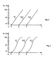
- Figs. 2, 3 and 4 show the rate of conveyed powder m p depending on the duration of opening t of the powder intake valves Q1 and Q2.
- the plots assume that the dense phase powder pump 10 has a response time delay t delay from the time to to the time t 1 ; that the second dense phase powder pump 10-2 has a response time delay t delay from the time t 0 to the time t 2 ; and that the third dense phase powder pump 10-3 has a response time delay from the time to to the time t 3 , in each case from the transmission of the command to open by the control unit 42 to the control valve 1.1 respectively 1.2 of the powder intake valve Q1 or Q2 until the onset of the coating powder stream through the at least partly open powder intake valve Q1 respectively Q2 to be opened.
- the response time delay t delay at the control unit 42 can be changed variably by means of a delay-time adjusting element 56 in said control unit 42 in a manner that the rectilinear lines of Fig. 2 or the curves of Fig. 3 of the three dense phase powder pumps 10, 10-2 and 10-3 coincide into a single curve.
- a setpoint for a given conveyed powder rate set at the powder adjusting element 54 of the control unit 42 will be the same rate of conveyed powder. In this manner the three dense phase powder pumps are compensated/calibrated with respect to each other.
- a variable time differential can be set at the delay time setting element 56 between a time at which the command to open the powder intake valve Q1 respectively Q2 can be generated at the powder adjusting element 54 and that time at which the command to open actually is transmitted from the control unit 42 to the control valve 1.1 respectively 1.2 of the powder intake valve Q1 respectively Q2 to be opened.
- a time differential can be set at the time delay adjusting element 56 between a time to start the suction stage defined by the setpoint at the powder setting element 54 and the actual generation in the control unit 42 of the command to open.
- Fig. 4 moreover shows how to vary the slope of the curves of the dense phase powder pumps 10, 10-2 and 10-3 by changing the apparatus constant C.
- This change in slope may be carried out in lieu of changing the time delay or in addition to it.
- the change in slope can be implemented in a manner that the maximum in percent of the conveyed powder rate is equal in all dense phase powder pumps 10, 10-2 and 10-3.
- the dependence modes may be stored in tabular form by means of which the control unit 42 calculates the same percentage per unit time for each adjustable percentage that can be set at the powder adjusting element 54 and accordingly controls the dense phase powder pump 10 by means of the control valves 1.1 through 1.7, as a result of which the dense powder pump 10 does in fact convey the set percentage rate of discharged powder.
- all the values t total , t delay , m p and C as well as others also may be transmitted in wireless manner or through electric circuits by means of signal to the control unit 42 and be adjustable therein for instance using BUS systems such as CAN, Profi-BUS or others.
Landscapes
- Application Of Or Painting With Fluid Materials (AREA)
- Coating Apparatus (AREA)
- Electrostatic Spraying Apparatus (AREA)
Description
- The present invention relates to a powder spray coating device - hereafter powder spraycoating equipment -- and to a powder transport device - hereafter powder feed apparatus - for said equipment.
- Dense phase powder pumps comprise at least one feed chamber fitted with a powder intake valve and a powder outlet valve. The feed chamber is alternatingly connected to a vacuum source during a suction stage and to a source of conveying compressed air during a discharge stage. The vacuum from said vacuum source aspirates powder through the open powder intake valve into .the feed chamber while the powder outlet valve is closed. The conveying compressed air from the source of conveying compressed air discharges powder from within the feed chamber through the open outlet valve while the intake valve is closed. Most dense phase powder pumps comprise two feed chambers operating at different time phases in order that alternatingly coating powder shall be aspirated each time into one feed chamber while the pertinent other feed chamber discharges coating powder.
- Different kinds of coating powder feed apparatus containing a dense phase powder pump are known for instance from the following documents:
JP 09/071325 A DE 196 11 533 B4 ,US 2000/0193704 A1 (=EP 1 644 131 A2 ),US 7 150 585 B2 (=WO 2004/087331 A1 ) andUS 2005/0178325 A1 (=EP 1 566 352 A2 ). A vacuum intake of at least one of the two feed chambers and in some embodiment modes also the compressed air intake of the feed chamber is/are fitted with a filter permeable to air but not to coating powder. The preferred filter material is a sintered one. Predominantly the powder intake and outlet valves are pinch valves. - The quantity of powder per unit time - hereafter powder rate -- fed by a dense phase powder pump in particular depends on the size (volume) of the feed chamber, on the frequency at which coating powder is aspirated into the feed chamber and then discharged from it, on the magnitude of the vacuum, on the time the powder intake valve is open during suction and on the flow impedances in the powder conduits upstream of the dense phase powder pump and especially downstream of it. The flow impedances depend in particular on the length and the inside cross-section of the powder conduits, mostly powder hoses. The compressed conveying air mixes only little with the coating powder which it pushes through the powder outlet valve out of the feed chamber.
- Different conditions apply to light phase powder pumps using injectors as the powder pump to feed the coating powder. Using a flow of conveying compressed air, a partial vacuum is generated in the injector. This partial vacuum aspirates coating powder into the conveying flow of compressed air. The mixture of powder and conveying compressed air flow moves from the injector to a target site, for instance a bin or a spray tool. The powder rate fed by the injector depends on the rate of conveying compressed air passing through the injector. Powder spraycoating equipment fitted with an injector illustratively is known from
US 4,284,032 .US 4,357,900 discloses powder spraycoating equipment wherein objects to be coated are moved through a cabin wherein they are automatically coated by spray tools driven by sensors, one of such sensors notifying a control unit when an object to be coated is being moved into said cabin in order that the spray tool be activated when said object moves into the coating range of said tool. Another sensor determines the kind of object involved, the electrical signals transmitted by this second sensor determining automatically the powder rate to be deposited on said object.EP 0 412 289 B1 discloses an electrostatic powder spraycoating apparatus fitted with an injector and with means keeping constant the total quantity of air fed to the spray tool and consisting of the conveying compressed air plus supplemental air that is added to the stream of powder.EP 0 636 420 A2 discloses powder spraycoating apparatus fitted with a control allowing adjusting the rate of fed powder and - depending on that adjustment and using stored functions - adjusting the rate of conveying compressed air and a rate of supplemental compressed air. Said functions are stored in graphic form. DocumentEP 1 772 195 shows another powder feed apparatus according to the preamble of claim 1. - Powder feed apparatus containing a dense phase powder pump incur the drawback that theoretically identical designs frequently entail nevertheless different rates of conveyed\ powder even when the same reference/setpoint values have been set. This feature is due to different tolerances and different material properties of theoretically identical parts materials. Illustratively pinch valves may display different response times when they differ in resilient deformations of their valve hoses. Another instance are different airflow impedances in a filter in the suction flow of the vacuum source.
- The objective of the present invention is to attain in simple manner approximately identical actual rates of powder stream for identical setpoint adjustments.
- This problem is solved by the features of claim of the present invention.
- The dependent claims of the present invention define further features.
- The present invention advantageously makes it possible to design powder spraycoating equipment and powder spray apparatus that are identical in theory but in practice differ on account of tolerance differentials and materials' deviations in a manner that a given setpoint of quantity of powder, for instance 60 % or another percentage of a maximally possible powder discharge rate of 100 % will assure in all equipment and apparatus the same actual value of powder rates (powder discharge rate).
- The present invention is elucidated below in relation to the appended drawings and illustrative embodiment modes.
-
Fig. 1 schematically shows powder spraycoating equipment of the invention comprising powder feed apparatus also of the present invention, -
Fig. 2 shows a graph of the invention, -
Fig. 3 shows another graph of the invention, and -
Fig. 4 shows still another graph of the invention. -
Fig. 1 schematically shows a powder feed apparatus of the invention which together with aspray tool 26 constitutes a powder spraycoating equipment. - The
spray tool 26 may be a manually operated spray gun or a controlled, automated spray means. Preferably it contains at least one high-voltage (hv)electrode 28 which is fed with hv from ahv source 30 to electrostatically charge thecoating powder 17 sprayed by thespray tool 26. Thehv source 30 may be integrated into thespray tool 26. Said spray tool may be fitted with a spray aperture 25 or with a rotary atomizer. - The dense
phase powder pump 10 contains at least one, preferably twofeed chambers 12 respectively 14 each in a pump part A respectively B. A powder intake valve Q1 respectively Q2 is integrated at a powder intake 12.1 or 14.1 of thefeed chamber feed chambers - Powder feed conduits 16.1 and 16.2 are connected to the intake side of the powder intake valves Q1 and Q2 and may run separately to one or two
powder bins 18, or, as shown inFig. 1 , they may be connected by means of abranch element 20 to the commonpowder feed conduit 16 running into thepowder bin 18. - The powder outlet side of the powder outlet valves Q3 and Q4 is connected by the powder discharge conduits 22.1 respectively 22.2 and a
branch element 24 to a commonpowder discharge conduit 22 connected to thespray tool 26. - Each
feed chamber vacuum source 44 or during a discharge stage to asource 48 of compressed conveying air. By means of said vacuum,coating powder 17 is aspirated through the open powder intake valve Q1 respectively Q2 into thefeed chamber 12 or 15 while the powder outlet valve Q3 or Q4 is closed. Using the compressed conveying air from thesource 48, the powder insidefeed chamber 12 respectively 14 is discharged through the open powder outlet valve Q3 or Q4 while the powder intake valve Q1 or Q2 is closed. The twofeed chambers feed chambers other feed chamber - The powder intake valves Q1 and Q2 and the powder outlet valves Q3 and Q4 may be controlled, arbitrary valves driven by the
control unit 42. Preferably however they shall be pinch valves fitted with aflexible hose 32 which subtends avalve duct 34 for the coating powder and which can be squeezed together by compressed air in the actuating pressurizedchamber 36 enclosing thehose 32 for the purpose of closing thevalve duct 34. Thehose 32 offers such resilience or intrinsic stress that after the pressure exerted by the compressed air is eliminated from the said actuation pressurizedchamber 36, said hose shall automatically straighten out and thereby open thevalve duct 34. -
Fig. 1 shows thefeed chamber 12 during the suction stage when its powder intake valve Q1 is open and its powder outlet valve Q3 is closed. Theother feed chamber 14 is in its powder discharge stage wherein its powder intake valve Q2 is closed and its powder discharge valve Q4 is open. - The powder intake valves Q1 and Q2 may be alternatingly fed by means of control valves 1.1 and 1.2 with compressed air from the
compressed air source 48 or be vented into the external atmosphere (or be connected to the vacuum source). The powder outlet valves Q3 and Q4 alternatingly can be loaded with compressed air by means of control valves 1.3 and 1.4 from thecompressed air source 48 or be vented (or connected to the vacuum source). Preferably a pressure regulator 2.2 shall be configured between the control valves 1.1, 1.2, 1.3 and 1.4 and thecompressed air source 48. In the preferred embodiment mode ofFig. 1 , a second pressure regulator 2.1 is configured in parallel with the pressure regulator 2.2 and one of the two pressure regulators can be connected by means of a further control valve 1.9 to the control valves 1.1, 1.2, 1.3 and 1.4. In this manner compressed air at the pressure of one of the pressure regulators 2.2 or at the pressure of the other pressure regulator 2.1 may alternatingly be applied to the powder valves Q1, Q2, Q3 and Q4. - An air exchange aperture 12.3 respectively 14.3 is fitted into a housing 12.6 and 14.6 to alternatingly apply a vacuum or compressed air to the
feed chamber feed chamber feed chambers - The air exchange apertures 12.3 and 14.3 can be alternatingly connected by control valves 1.5 and 1.6 and the
control unit 42 with thecompressed air source 48 or thevacuum source 44. - The present invention moreover may include a control valve 1.8 in order to directly connect the air exchange apertures/hookups 12.3 and 14. 3 to the
compressed air source 48 instead of through a pressure regulator in thecontrol unit 42. - A
compressed air conduit 52 connects thecontrol unit 42 to the control valves 1.5 and 1.6.Compressed air conduits 46 connect thecompressed air source 48 to the pressure regulators 2.1 and 2.2. - Illustratively the
vacuum source 44 may be fitted with an injector wherein a flow of compressed air creates a (partial) vacuum at avacuum hookup 50. The flow of compressed air illustratively may be fed by a pressure regulator 2.3 and a control valve 1.7 to thevacuum injector 44. The pressure regulator 2.3 is connected through thecompressed air conduit 46 to thecompressed air source 48. All control valves 1.1, 1.2, 1.3, 1.4, 1.5, 1.6, 1.7, 1.8 and 1.9 are driven by thecontrol unit 42. - The
electrical control unit 42 contains at least one computer driving the densephase powder pump 10 by means of the control valves 1.1, 1.2, 1.3, 1.4, 1.5 and 1.6, and, to the extent being used, also the control valves 1.7, 1.8 and 1.9. - The
control unit 42 stores the time function ttotal of the total opening duration of the powder intake valves Q1 and Q2 defining the dependence of said function on the (nominal) reference value mp adjustable at thecontrol unit 42 by means of apowder adjusting element 54 for the powder stream rate conveyed by the densephase powder pump 10, further on a response delay tdelay and an apparatus constant C. The powder rate is that percentage powder rate delivered by the dense phase powder pump. The response delay time tdelay is that duration elapsing between the transmission of a command to open from thecontrol unit 42 to one of the control valves 1.1 and 1.2 to open the pertinent power intake valve Q1 or Q2 of thefeed chamber feed chamber powder adjusting element 54 is from 0 to 100 %, this range being divided into corresponding values from 0 to 100 % of the particular delivered powder rate from the dense phase powder pump 120. The value of 0 % denotes the state of the onset of powder flow through the powder intake valve Q1 respectively Q2 of thefeed chamber phase powder pump 10 at a defined maximum duration of opening of the powder intake valves Q1 respectively Q2 of thefeed chambers - The present invention is applicable also to dense phase powder pumps which, instead of two, only comprise one
feed chamber - In the preferred embodiment mode of the invention, the adjustment range division of the
powder adjusting element 54 is linear from 0 to 100 and each setpoint percentage linearly corresponds to the percentage of the actually moved powder discharge rate of the densephase powder pump 10. - The dependency relation may be implemented in different kinds and be stored in hardware or software in the
control unit 42. - In a preferred implementation of the present invention, the dependency relation is stored in the form of a mathematical function by means of which the
control unit 42 calculates - for each percentage adjustable at the powder adjusting element 54 - the pertinent equal percentage of powder discharge rate and controls accordingly the densephase pump powder 10 whereby it feeds the calculated powder discharge rate. - Preferably the mathematical formula shall be stated as follows:

- In this formula, ttotal denotes the total duration (measured in ms) of the suction stage from the onset of the command to open the powder intake valve Q1 or Q2 to the onset of a command to close transmitted by the
control unit 42 to the powder intake valve Q1 respectively Q2. The term tdelay denotes the response delay time (measured in ms) from the onset of the command to open to the onset of coating powder flow through the at least partly opened powder intake valve Q1 respectively Q2 to be opened. The term mp denotes the rate of powder stream (setpoint) in percent relative the maximally possible powder rate at a predetermined maximum duration of open powder intake valve Q1' respectively Q2. The term C is an empirically determined value relating to the powder feed apparatus and depends on its design and also may be affected by the powder flow impedance downstream of the dense phase powder pump. - In another mode implementing the present invention, the dependence mode may be stored in the form of a rectilinear or curved function plot by means of which - for each adjustable percentage set at the powder setting element 54 - the
control unit 42 calculates the same corresponding percentage of the powder discharge rate and the densephase powder pump 10 by means of the control valves 1.1 through 1.7 commensurately controls the calculation, as a result of which the densephase powder pump 10 conveys the percentage of powder discharge rate as was set at thepowder adjusting element 54. - As regards the dense phase powder pumps 10, 10-2 and 10-3 of three theoretically identical powder feed apparatus,
Figs. 2, 3 and4 show the rate of conveyed powder mp depending on the duration of opening t of the powder intake valves Q1 and Q2. The plots assume that the densephase powder pump 10 has a response time delay tdelay from the time to to the time t1; that the second dense phase powder pump 10-2 has a response time delay tdelay from the time t0 to the time t2; and that the third dense phase powder pump 10-3 has a response time delay from the time to to the time t3, in each case from the transmission of the command to open by thecontrol unit 42 to the control valve 1.1 respectively 1.2 of the powder intake valve Q1 or Q2 until the onset of the coating powder stream through the at least partly open powder intake valve Q1 respectively Q2 to be opened. - In a preferred embodiment mode of the present invention, the response time delay tdelay at the
control unit 42 can be changed variably by means of a delay-time adjusting element 56 in saidcontrol unit 42 in a manner that the rectilinear lines ofFig. 2 or the curves ofFig. 3 of the three dense phase powder pumps 10, 10-2 and 10-3 coincide into a single curve. As a result, a setpoint for a given conveyed powder rate set at thepowder adjusting element 54 of thecontrol unit 42 will be the same rate of conveyed powder. In this manner the three dense phase powder pumps are compensated/calibrated with respect to each other. - The adjustable change in response time delay feasible at the delay
time setting element 56 can be implemented in different ways. In one preferred embodiment mode of the present invention, a variable time differential can be set at the delaytime setting element 56 between a time at which the command to open the powder intake valve Q1 respectively Q2 can be generated at thepowder adjusting element 54 and that time at which the command to open actually is transmitted from thecontrol unit 42 to the control valve 1.1 respectively 1.2 of the powder intake valve Q1 respectively Q2 to be opened. In another embodiment mode of the present invention, a time differential can be set at the timedelay adjusting element 56 between a time to start the suction stage defined by the setpoint at thepowder setting element 54 and the actual generation in thecontrol unit 42 of the command to open. -
Fig. 4 moreover shows how to vary the slope of the curves of the dense phase powder pumps 10, 10-2 and 10-3 by changing the apparatus constant C. This change in slope may be carried out in lieu of changing the time delay or in addition to it. The change in slope can be implemented in a manner that the maximum in percent of the conveyed powder rate is equal in all dense phase powder pumps 10, 10-2 and 10-3. - In another embodiment of the present invention, the dependence modes may be stored in tabular form by means of which the
control unit 42 calculates the same percentage per unit time for each adjustable percentage that can be set at thepowder adjusting element 54 and accordingly controls the densephase powder pump 10 by means of the control valves 1.1 through 1.7, as a result of which thedense powder pump 10 does in fact convey the set percentage rate of discharged powder. - Instead of being driven manually, all the values ttotal, tdelay, mp and C as well as others also may be transmitted in wireless manner or through electric circuits by means of signal to the
control unit 42 and be adjustable therein for instance using BUS systems such as CAN, Profi-BUS or others.
Claims (9)
- A powder feed apparatus of a powder spraycoating equipment, comprising a dense phase powder pump (10) containing at least one feed chamber (12, 14), preferably two feed chambers (12, 14) alternatingly discharging coating powder, of which each feed chamber (12, 14) is fitted with a powder intake valve (Q1, Q2) at a powder intake (12.1) to aspirate coating powder during a suction stage and with a powder outlet valve (Q3, Q4) at a powder outlet (12.2, 14.2) to discharge coating powder during a discharge stage; further control valves (1.1, 1.2, 1.3, 1.4, 1.5, 1.6, 1.7) to operate the den se phase powder pump (1-0); further an electric control unit (42) containing at least one computer to control by means of said control valves the dense phase power pump (10),
characterized in that
the control unit (42) stores a function of the total open time (ttotal) of the powder intake valve (Q1, Q2) according to which the dense phase powder pump (10) is controlled by means of said further control valves (1.1-1.7), said function defining the dependence of this total open time (ttotal) on a reference value (mp) adjustable at the control unit (42) by means of a powder adjusting element (54) concerning the rate of powder stream to be moved by the dense phase powder pump (10), further on a response delay time (tdelay) and on an equipment constant C in that ttotal = tdelay + mp C, where ttotal is the total duration of the suction stage from the onset of the command to open to the onset of the command to close from the control unit (42) concerning the closing powder intake valve (Q1, Q2), where the response delay time is that time elapsing during a suction stage between the transmission of a command from the control unit (42) to one of the control valves (1.1 - 1.7) to open the powder intake valves (Q1, Q2) of the minimum of one feed chamber (12, 14) and the onset of a powder stream into this feed chamber through the powder intake valve (Q1, Q2) which is at least partly open, where mp denotes the percentage of the powder rate fed by the dense phase powder pump (10) relative to the maximally possible rate of powder at a predetermined maximum opening time of the powder intake valve (Q1, Q2), where C is a characteristic value determined by experiment and depending on the design of the powder feed apparatus and possibly also on the powder stream impedance downstream of the dense phase powder pump (10), and where the powder adjusting element (54) has an adjustment range of 0 to 100 %, said range being divided into corresponding 0 to 100 % portions of the particular rate of conveyed discharged powder of the dense phase powder pump (10), where 0 % corresponds to no powder being discharged at the end of the response delay time, just when the coating powder begins streaming through the powder intake valve of the feed chamber (12, 14) in its suction stage and where 100 % corresponds to the maximally possible rate of powder discharge of the dense phase powder pump (10) at a defined maximum time of opening of the powder intake valve (Q1, Q2) of the minimum of one feed chamber (12, 14). - Powder feed apparatus as claimed in claim 1, characterized in that the partitioning of the adjustment range of the powder adjusting element (54) from 0 to 100 % is linear and each adjusted percentage linearly corresponds to the percentage of the instantaneously conveyed powder discharge rate.
- Powder feed apparatus as claimed in either of claims 1 and 2, characterized in that the function is stored as a mathematical function by means of which the control unit calculates - for each percentage adjustable at the powder adjusting element (54) - the same percentage of the rate of discharged powder and correspondingly controls the dense phase powder pump (10), said control unit thereby conveying the calculated percentage of the rate of discharged powder.
- Powder feed apparatus as claimed in either of claims 1 and 2, characterized in that the function is stored in the form of a plot of curves by means of which the control unit (42) calculates - for each adjustable percentage at the powder adjusting element (54) - the same percentage of the rate of discharged powder and correspondingly drives the dense phase powder pump (10) by means of the control valves (1.1 - 1.7), so that said control unit conveys the percentage rate of discharged powder set at the powder adjusting element (54).
- Powder feed apparatus as claimed in either of claims 1 and 2, characterized in that the function is stored in tabular form by means of which the control unit (42) calculates - for each percentage adjustable at the powder adjusting element (54) - the same percentage of the rate of discharged powder and correspondingly drives by means of the control valves (1.1 - 1.7) the dense phase powder pump (10), as a result of which the dense phase powder pump (10) actually does convey the adjusted percentage of the rate of discharged powder.
- Powder feed apparatus as claimed in one of the above claims, characterized in that the response delay time may be variably changed in different ways at the control unit (42) by means of a delay time adjusting element (56) in the control unit (42), preferably by using a time differential - adjustable by a at the time delay adjusting element (56) - between that time defined by a powder feed setpoint at the powder adjusting element (54) and that time at which the command to open is in fact being generated, or, in another embodiment mode, wherein the command to open is generated at once, that time at which the command to open is transmitted by the signal unit (42) to open the powder intake valve (Q1, Q2).
- Powder feed apparatus as claimed in one of the above claims, characterized in that the minimum of one powder intake valve (Q1, Q2) and the minimum of one powder outlet valve (Q3, Q4) all are pinch valves.
- Powder feed apparatus as claimed in claim 7, characterized in that the pinch valves are designed to have a flexible hose (32) subtending a coating powder valve duct (34) and being totally collapsible by means of compressed air from a compressed air chamber (36) enclosing it when the valve duct (34) is to be closed, and where, due to the mechanically prestressed hose, it shall by itself automatically reopen when the compressed air is no longer applied.
- Powder spraycoating equipment, containing a powder feed apparatus defined in one of the above claims.
Priority Applications (1)
| Application Number | Priority Date | Filing Date | Title |
|---|---|---|---|
| PL08807086T PL2190590T3 (en) | 2007-09-29 | 2008-09-15 | Powder spray coating device and powder transport device therefor |
Applications Claiming Priority (2)
| Application Number | Priority Date | Filing Date | Title |
|---|---|---|---|
| DE102007046806A DE102007046806A1 (en) | 2007-09-29 | 2007-09-29 | Powder spray coating device and powder conveying device therefor |
| PCT/IB2008/002402 WO2009044242A1 (en) | 2007-09-29 | 2008-09-15 | Powder spray coating device and powder transport device therefor |
Publications (2)
| Publication Number | Publication Date |
|---|---|
| EP2190590A1 EP2190590A1 (en) | 2010-06-02 |
| EP2190590B1 true EP2190590B1 (en) | 2014-04-16 |
Family
ID=40325855
Family Applications (1)
| Application Number | Title | Priority Date | Filing Date |
|---|---|---|---|
| EP08807086.7A Active EP2190590B1 (en) | 2007-09-29 | 2008-09-15 | Powder spray coating device and powder transport device therefor |
Country Status (8)
| Country | Link |
|---|---|
| US (1) | US8430640B2 (en) |
| EP (1) | EP2190590B1 (en) |
| DE (1) | DE102007046806A1 (en) |
| DK (1) | DK2190590T3 (en) |
| ES (1) | ES2473465T3 (en) |
| PL (1) | PL2190590T3 (en) |
| PT (1) | PT2190590E (en) |
| WO (1) | WO2009044242A1 (en) |
Families Citing this family (9)
| Publication number | Priority date | Publication date | Assignee | Title |
|---|---|---|---|---|
| WO2010055861A1 (en) | 2008-11-14 | 2010-05-20 | ジェイパワー・エンテック株式会社 | Lock hopper |
| DE102011004035A1 (en) * | 2011-02-14 | 2012-08-16 | Illinois Tool Works Inc. | Powder pump for conveying coating powder |
| DE102011052432A1 (en) * | 2011-04-15 | 2012-10-18 | Reinhausen Plasma Gmbh | Diaphragm pump and method for conveying fine-grained powders by means of a diaphragm pump |
| EP2836307A1 (en) | 2012-04-13 | 2015-02-18 | Nordson Corporation | Powder gun configurable for supply from venturi or dense phase pump |
| DE102013211550A1 (en) | 2013-06-19 | 2014-12-24 | Gema Switzerland Gmbh | Powder conveying device, in particular for coating powder |
| DE102015108492A1 (en) | 2015-05-29 | 2016-12-01 | Gema Switzerland Gmbh | Method for operating a powder seal pump and powder seal pump |
| US12564849B2 (en) | 2017-02-21 | 2026-03-03 | Gema Switzerland Gmbh | Dense phase powder pump |
| DE102017103487A1 (en) | 2017-02-21 | 2018-08-23 | Gema Switzerland Gmbh | POWDER SEALING POWER PUMP |
| CN120286218A (en) * | 2025-06-13 | 2025-07-11 | 常州铭捷智能装备有限公司 | A comprehensive control system for high-precision quantitative powder delivery |
Family Cites Families (21)
| Publication number | Priority date | Publication date | Assignee | Title |
|---|---|---|---|---|
| US2600493A (en) * | 1948-05-19 | 1952-06-17 | Victor W Farris | Pinch valve |
| NL288142A (en) * | 1962-01-25 | 1900-01-01 | ||
| DE2849295C2 (en) | 1978-11-14 | 1985-04-04 | Ransburg-Gema AG, St.Gallen | Spray coating device for coating objects |
| US4268005A (en) * | 1978-12-08 | 1981-05-19 | Red Valve Company, Inc. | Pinch valve |
| DE3014114C2 (en) | 1980-04-12 | 1982-04-29 | Gema AG Apparatebau, 9015 St. Gallen | Device for the automatic coating of objects with a spray device |
| DE8915968U1 (en) | 1989-08-11 | 1992-12-17 | Gema Volstatic Ag, St. Gallen | Electrostatic powder coating equipment |
| CA2049618A1 (en) * | 1991-07-18 | 1993-01-19 | Christopher J. O'brien | Integrated transmitter and controller |
| FR2680416B1 (en) * | 1991-08-12 | 1995-06-30 | Sames Sa | FLUIDIZED POWDER FLOW MEASURING METHOD AND FLOW MEASURING DEVICE USING SUCH A METHOD. |
| DE4325044C2 (en) | 1993-07-26 | 2002-07-18 | Itw Gema Ag | Powder conveying device, in particular for coating powder |
| JPH0971325A (en) | 1995-09-06 | 1997-03-18 | Kazutoshi Ogawa | Pneumatic powder material transporting device |
| DE19611533B4 (en) | 1996-03-23 | 2005-11-03 | Itw Gema Ag | Device for powder coating |
| DE19838279A1 (en) * | 1998-08-22 | 2000-02-24 | Itw Gema Ag | Powder coating system has an injector stage with air supply controlled by restrictor valves that are coupled to a processor |
| JP5241996B2 (en) | 2002-10-14 | 2013-07-17 | ノードソン コーポレーション | Method and apparatus for transporting powdered material |
| DE10300280A1 (en) * | 2003-01-08 | 2004-07-22 | Itw Gema Ag | Pump device for powder, process therefor and powder coating device |
| ITMI20031419A1 (en) | 2003-07-11 | 2005-01-12 | Studio A Z Di Giancarlo Simontacchi | DEVICE FOR THE TRANSPORT OF POWDERS THROUGH PIPES |
| US7793869B2 (en) * | 2003-08-18 | 2010-09-14 | Nordson Corporation | Particulate material applicator and pump |
| DE102004007967A1 (en) | 2004-02-18 | 2005-09-08 | Dürr Systems GmbH | Powder feed pump and associated operating method |
| DE102004008495A1 (en) | 2004-02-20 | 2005-09-08 | Dürr Systems GmbH | Powder feed pump |
| US7204158B2 (en) * | 2004-07-07 | 2007-04-17 | Parker-Hannifin Corporation | Flow control apparatus and method with internally isothermal control volume for flow verification |
| DE102005006522B3 (en) * | 2005-02-11 | 2006-08-03 | J. Wagner Ag | Feed device for coating powder has controllable inlet and outlet valves, powder feed chamber formed from elastic feed chamber hose |
| US7731456B2 (en) * | 2005-10-07 | 2010-06-08 | Nordson Corporation | Dense phase pump with open loop control |
-
2007
- 2007-09-29 DE DE102007046806A patent/DE102007046806A1/en not_active Withdrawn
-
2008
- 2008-09-15 PT PT88070867T patent/PT2190590E/en unknown
- 2008-09-15 DK DK08807086.7T patent/DK2190590T3/en active
- 2008-09-15 ES ES08807086.7T patent/ES2473465T3/en active Active
- 2008-09-15 US US12/680,204 patent/US8430640B2/en active Active
- 2008-09-15 WO PCT/IB2008/002402 patent/WO2009044242A1/en not_active Ceased
- 2008-09-15 PL PL08807086T patent/PL2190590T3/en unknown
- 2008-09-15 EP EP08807086.7A patent/EP2190590B1/en active Active
Also Published As
| Publication number | Publication date |
|---|---|
| WO2009044242A1 (en) | 2009-04-09 |
| US20100243759A1 (en) | 2010-09-30 |
| PT2190590E (en) | 2014-06-25 |
| DK2190590T3 (en) | 2014-06-30 |
| EP2190590A1 (en) | 2010-06-02 |
| PL2190590T3 (en) | 2014-09-30 |
| US8430640B2 (en) | 2013-04-30 |
| ES2473465T3 (en) | 2014-07-07 |
| DE102007046806A1 (en) | 2009-04-02 |
Similar Documents
| Publication | Publication Date | Title |
|---|---|---|
| US8430640B2 (en) | Powder spray coating device and powder transport device therefor | |
| US11033916B2 (en) | Powder-dispensing device and powder-coating installation for spraying articles with a powder coating | |
| EP2195118B1 (en) | Feeding device for powder spray coating device | |
| EP2209560B1 (en) | Powder spraycoating control system and its combination with powder feeding device or with powder spraycoating device | |
| US9834391B2 (en) | Powder feeding device, in particular for coating powder | |
| CN105121027B (en) | Powder delivery apparatus and associated method of operation | |
| EP2190588B1 (en) | Powder feeding method, powder feeding apparatus and electrostatical powder spray coating apparatus | |
| EP2190589B1 (en) | Powder spray coating method and device therefor | |
| JP2002523216A (en) | Powder spray coating equipment | |
| US6851936B2 (en) | Vacuum producing device | |
| CN104394998A (en) | Electrostatic spray tool power supply | |
| US12350697B2 (en) | Powder dispensing device with a dilute phase powder pump | |
| US6443670B1 (en) | Powder coating equipment having zero-sum control of conveyance and supplement air lines | |
| US20050002742A1 (en) | Method and device for transporting powdery substances | |
| CN211117873U (en) | Locator flame proof respiratory device | |
| WO2009047601A2 (en) | Dense phase powder pump comprising a supply hose having a specific inside roughness | |
| WO2026024254A1 (en) | Three-chamber application pump for powder coating | |
| CN110822151A (en) | Locator flame proof respiratory device | |
| KR20050005460A (en) | Method for regulating flow of powder carried by an air stream and device therefor |
Legal Events
| Date | Code | Title | Description |
|---|---|---|---|
| PUAI | Public reference made under article 153(3) epc to a published international application that has entered the european phase |
Free format text: ORIGINAL CODE: 0009012 |
|
| 17P | Request for examination filed |
Effective date: 20100217 |
|
| AK | Designated contracting states |
Kind code of ref document: A1 Designated state(s): AT BE BG CH CY CZ DE DK EE ES FI FR GB GR HR HU IE IS IT LI LT LU LV MC MT NL NO PL PT RO SE SI SK TR |
|
| AX | Request for extension of the european patent |
Extension state: AL BA MK RS |
|
| DAX | Request for extension of the european patent (deleted) | ||
| RAP1 | Party data changed (applicant data changed or rights of an application transferred) |
Owner name: GEMA SWITZERLAND GMBH |
|
| GRAP | Despatch of communication of intention to grant a patent |
Free format text: ORIGINAL CODE: EPIDOSNIGR1 |
|
| INTG | Intention to grant announced |
Effective date: 20131121 |
|
| RIN1 | Information on inventor provided before grant (corrected) |
Inventor name: MAUCHLE, FELIX Inventor name: MARXER, CHRISTIAN |
|
| GRAS | Grant fee paid |
Free format text: ORIGINAL CODE: EPIDOSNIGR3 |
|
| GRAA | (expected) grant |
Free format text: ORIGINAL CODE: 0009210 |
|
| AK | Designated contracting states |
Kind code of ref document: B1 Designated state(s): AT BE BG CH CY CZ DE DK EE ES FI FR GB GR HR HU IE IS IT LI LT LU LV MC MT NL NO PL PT RO SE SI SK TR |
|
| REG | Reference to a national code |
Ref country code: GB Ref legal event code: FG4D |
|
| REG | Reference to a national code |
Ref country code: CH Ref legal event code: NV Representative=s name: FIAMMENGHI-FIAMMENGHI, CH Ref country code: CH Ref legal event code: EP |
|
| REG | Reference to a national code |
Ref country code: AT Ref legal event code: REF Ref document number: 662173 Country of ref document: AT Kind code of ref document: T Effective date: 20140515 |
|
| REG | Reference to a national code |
Ref country code: IE Ref legal event code: FG4D |
|
| REG | Reference to a national code |
Ref country code: DE Ref legal event code: R096 Ref document number: 602008031578 Country of ref document: DE Effective date: 20140605 |
|
| REG | Reference to a national code |
Ref country code: SE Ref legal event code: TRGR |
|
| REG | Reference to a national code |
Ref country code: PT Ref legal event code: SC4A Free format text: AVAILABILITY OF NATIONAL TRANSLATION Effective date: 20140617 |
|
| REG | Reference to a national code |
Ref country code: DK Ref legal event code: T3 Effective date: 20140627 |
|
| REG | Reference to a national code |
Ref country code: ES Ref legal event code: FG2A Ref document number: 2473465 Country of ref document: ES Kind code of ref document: T3 Effective date: 20140707 |
|
| REG | Reference to a national code |
Ref country code: NL Ref legal event code: T3 |
|
| REG | Reference to a national code |
Ref country code: LT Ref legal event code: MG4D |
|
| REG | Reference to a national code |
Ref country code: PL Ref legal event code: T3 |
|
| PG25 | Lapsed in a contracting state [announced via postgrant information from national office to epo] |
Ref country code: BG Free format text: LAPSE BECAUSE OF FAILURE TO SUBMIT A TRANSLATION OF THE DESCRIPTION OR TO PAY THE FEE WITHIN THE PRESCRIBED TIME-LIMIT Effective date: 20140716 Ref country code: LT Free format text: LAPSE BECAUSE OF FAILURE TO SUBMIT A TRANSLATION OF THE DESCRIPTION OR TO PAY THE FEE WITHIN THE PRESCRIBED TIME-LIMIT Effective date: 20140416 Ref country code: NO Free format text: LAPSE BECAUSE OF FAILURE TO SUBMIT A TRANSLATION OF THE DESCRIPTION OR TO PAY THE FEE WITHIN THE PRESCRIBED TIME-LIMIT Effective date: 20140716 Ref country code: GR Free format text: LAPSE BECAUSE OF FAILURE TO SUBMIT A TRANSLATION OF THE DESCRIPTION OR TO PAY THE FEE WITHIN THE PRESCRIBED TIME-LIMIT Effective date: 20140717 Ref country code: CY Free format text: LAPSE BECAUSE OF FAILURE TO SUBMIT A TRANSLATION OF THE DESCRIPTION OR TO PAY THE FEE WITHIN THE PRESCRIBED TIME-LIMIT Effective date: 20140416 Ref country code: FI Free format text: LAPSE BECAUSE OF FAILURE TO SUBMIT A TRANSLATION OF THE DESCRIPTION OR TO PAY THE FEE WITHIN THE PRESCRIBED TIME-LIMIT Effective date: 20140416 Ref country code: IS Free format text: LAPSE BECAUSE OF FAILURE TO SUBMIT A TRANSLATION OF THE DESCRIPTION OR TO PAY THE FEE WITHIN THE PRESCRIBED TIME-LIMIT Effective date: 20140816 |
|
| PGFP | Annual fee paid to national office [announced via postgrant information from national office to epo] |
Ref country code: DK Payment date: 20140925 Year of fee payment: 7 |
|
| PG25 | Lapsed in a contracting state [announced via postgrant information from national office to epo] |
Ref country code: LV Free format text: LAPSE BECAUSE OF FAILURE TO SUBMIT A TRANSLATION OF THE DESCRIPTION OR TO PAY THE FEE WITHIN THE PRESCRIBED TIME-LIMIT Effective date: 20140416 Ref country code: HR Free format text: LAPSE BECAUSE OF FAILURE TO SUBMIT A TRANSLATION OF THE DESCRIPTION OR TO PAY THE FEE WITHIN THE PRESCRIBED TIME-LIMIT Effective date: 20140416 |
|
| PGFP | Annual fee paid to national office [announced via postgrant information from national office to epo] |
Ref country code: ES Payment date: 20140926 Year of fee payment: 7 Ref country code: AT Payment date: 20140820 Year of fee payment: 7 Ref country code: PL Payment date: 20140902 Year of fee payment: 7 Ref country code: SE Payment date: 20140929 Year of fee payment: 7 |
|
| PGFP | Annual fee paid to national office [announced via postgrant information from national office to epo] |
Ref country code: PT Payment date: 20140617 Year of fee payment: 7 |
|
| REG | Reference to a national code |
Ref country code: DE Ref legal event code: R097 Ref document number: 602008031578 Country of ref document: DE |
|
| PG25 | Lapsed in a contracting state [announced via postgrant information from national office to epo] |
Ref country code: EE Free format text: LAPSE BECAUSE OF FAILURE TO SUBMIT A TRANSLATION OF THE DESCRIPTION OR TO PAY THE FEE WITHIN THE PRESCRIBED TIME-LIMIT Effective date: 20140416 Ref country code: SK Free format text: LAPSE BECAUSE OF FAILURE TO SUBMIT A TRANSLATION OF THE DESCRIPTION OR TO PAY THE FEE WITHIN THE PRESCRIBED TIME-LIMIT Effective date: 20140416 Ref country code: RO Free format text: LAPSE BECAUSE OF FAILURE TO SUBMIT A TRANSLATION OF THE DESCRIPTION OR TO PAY THE FEE WITHIN THE PRESCRIBED TIME-LIMIT Effective date: 20140416 Ref country code: CZ Free format text: LAPSE BECAUSE OF FAILURE TO SUBMIT A TRANSLATION OF THE DESCRIPTION OR TO PAY THE FEE WITHIN THE PRESCRIBED TIME-LIMIT Effective date: 20140416 |
|
| PLBE | No opposition filed within time limit |
Free format text: ORIGINAL CODE: 0009261 |
|
| STAA | Information on the status of an ep patent application or granted ep patent |
Free format text: STATUS: NO OPPOSITION FILED WITHIN TIME LIMIT |
|
| PGFP | Annual fee paid to national office [announced via postgrant information from national office to epo] |
Ref country code: NL Payment date: 20140926 Year of fee payment: 7 |
|
| 26N | No opposition filed |
Effective date: 20150119 |
|
| PG25 | Lapsed in a contracting state [announced via postgrant information from national office to epo] |
Ref country code: MC Free format text: LAPSE BECAUSE OF FAILURE TO SUBMIT A TRANSLATION OF THE DESCRIPTION OR TO PAY THE FEE WITHIN THE PRESCRIBED TIME-LIMIT Effective date: 20140416 Ref country code: LU Free format text: LAPSE BECAUSE OF FAILURE TO SUBMIT A TRANSLATION OF THE DESCRIPTION OR TO PAY THE FEE WITHIN THE PRESCRIBED TIME-LIMIT Effective date: 20140915 |
|
| PGFP | Annual fee paid to national office [announced via postgrant information from national office to epo] |
Ref country code: BE Payment date: 20140929 Year of fee payment: 7 |
|
| REG | Reference to a national code |
Ref country code: DE Ref legal event code: R097 Ref document number: 602008031578 Country of ref document: DE Effective date: 20150119 |
|
| REG | Reference to a national code |
Ref country code: IE Ref legal event code: MM4A |
|
| PG25 | Lapsed in a contracting state [announced via postgrant information from national office to epo] |
Ref country code: SI Free format text: LAPSE BECAUSE OF FAILURE TO SUBMIT A TRANSLATION OF THE DESCRIPTION OR TO PAY THE FEE WITHIN THE PRESCRIBED TIME-LIMIT Effective date: 20140416 |
|
| PG25 | Lapsed in a contracting state [announced via postgrant information from national office to epo] |
Ref country code: IE Free format text: LAPSE BECAUSE OF NON-PAYMENT OF DUE FEES Effective date: 20140915 |
|
| REG | Reference to a national code |
Ref country code: PT Ref legal event code: MM4A Free format text: LAPSE DUE TO NON-PAYMENT OF FEES Effective date: 20160315 |
|
| REG | Reference to a national code |
Ref country code: DK Ref legal event code: EBP Effective date: 20150930 |
|
| REG | Reference to a national code |
Ref country code: SE Ref legal event code: EUG |
|
| REG | Reference to a national code |
Ref country code: AT Ref legal event code: MM01 Ref document number: 662173 Country of ref document: AT Kind code of ref document: T Effective date: 20150915 |
|
| PG25 | Lapsed in a contracting state [announced via postgrant information from national office to epo] |
Ref country code: PT Free format text: LAPSE BECAUSE OF NON-PAYMENT OF DUE FEES Effective date: 20160315 Ref country code: SE Free format text: LAPSE BECAUSE OF NON-PAYMENT OF DUE FEES Effective date: 20150916 |
|
| REG | Reference to a national code |
Ref country code: NL Ref legal event code: MM Effective date: 20151001 |
|
| PG25 | Lapsed in a contracting state [announced via postgrant information from national office to epo] |
Ref country code: MT Free format text: LAPSE BECAUSE OF FAILURE TO SUBMIT A TRANSLATION OF THE DESCRIPTION OR TO PAY THE FEE WITHIN THE PRESCRIBED TIME-LIMIT Effective date: 20140416 |
|
| PG25 | Lapsed in a contracting state [announced via postgrant information from national office to epo] |
Ref country code: HU Free format text: LAPSE BECAUSE OF FAILURE TO SUBMIT A TRANSLATION OF THE DESCRIPTION OR TO PAY THE FEE WITHIN THE PRESCRIBED TIME-LIMIT; INVALID AB INITIO Effective date: 20080915 |
|
| PG25 | Lapsed in a contracting state [announced via postgrant information from national office to epo] |
Ref country code: NL Free format text: LAPSE BECAUSE OF NON-PAYMENT OF DUE FEES Effective date: 20151001 Ref country code: AT Free format text: LAPSE BECAUSE OF NON-PAYMENT OF DUE FEES Effective date: 20150915 |
|
| REG | Reference to a national code |
Ref country code: FR Ref legal event code: PLFP Year of fee payment: 9 |
|
| PG25 | Lapsed in a contracting state [announced via postgrant information from national office to epo] |
Ref country code: DK Free format text: LAPSE BECAUSE OF NON-PAYMENT OF DUE FEES Effective date: 20150930 |
|
| PG25 | Lapsed in a contracting state [announced via postgrant information from national office to epo] |
Ref country code: PL Free format text: LAPSE BECAUSE OF NON-PAYMENT OF DUE FEES Effective date: 20150915 |
|
| PG25 | Lapsed in a contracting state [announced via postgrant information from national office to epo] |
Ref country code: ES Free format text: LAPSE BECAUSE OF NON-PAYMENT OF DUE FEES Effective date: 20150916 |
|
| PG25 | Lapsed in a contracting state [announced via postgrant information from national office to epo] |
Ref country code: BE Free format text: LAPSE BECAUSE OF NON-PAYMENT OF DUE FEES Effective date: 20150930 |
|
| REG | Reference to a national code |
Ref country code: FR Ref legal event code: PLFP Year of fee payment: 10 |
|
| REG | Reference to a national code |
Ref country code: FR Ref legal event code: PLFP Year of fee payment: 11 |
|
| P01 | Opt-out of the competence of the unified patent court (upc) registered |
Effective date: 20230621 |
|
| REG | Reference to a national code |
Ref country code: CH Ref legal event code: U11 Free format text: ST27 STATUS EVENT CODE: U-0-0-U10-U11 (AS PROVIDED BY THE NATIONAL OFFICE) Effective date: 20251001 |
|
| PGFP | Annual fee paid to national office [announced via postgrant information from national office to epo] |
Ref country code: DE Payment date: 20250929 Year of fee payment: 18 |
|
| PGFP | Annual fee paid to national office [announced via postgrant information from national office to epo] |
Ref country code: TR Payment date: 20250822 Year of fee payment: 18 Ref country code: IT Payment date: 20250919 Year of fee payment: 18 |
|
| PGFP | Annual fee paid to national office [announced via postgrant information from national office to epo] |
Ref country code: GB Payment date: 20250929 Year of fee payment: 18 |
|
| PGFP | Annual fee paid to national office [announced via postgrant information from national office to epo] |
Ref country code: FR Payment date: 20250925 Year of fee payment: 18 |
|
| PGFP | Annual fee paid to national office [announced via postgrant information from national office to epo] |
Ref country code: CH Payment date: 20251001 Year of fee payment: 18 |