EP2190264A1 - Evaporation apparatus - Google Patents
Evaporation apparatus Download PDFInfo
- Publication number
- EP2190264A1 EP2190264A1 EP08831052A EP08831052A EP2190264A1 EP 2190264 A1 EP2190264 A1 EP 2190264A1 EP 08831052 A EP08831052 A EP 08831052A EP 08831052 A EP08831052 A EP 08831052A EP 2190264 A1 EP2190264 A1 EP 2190264A1
- Authority
- EP
- European Patent Office
- Prior art keywords
- substrate
- organic material
- vapor
- vapor deposition
- mask
- Prior art date
- Legal status (The legal status is an assumption and is not a legal conclusion. Google has not performed a legal analysis and makes no representation as to the accuracy of the status listed.)
- Withdrawn
Links
Images



Classifications
-
- C—CHEMISTRY; METALLURGY
- C23—COATING METALLIC MATERIAL; COATING MATERIAL WITH METALLIC MATERIAL; CHEMICAL SURFACE TREATMENT; DIFFUSION TREATMENT OF METALLIC MATERIAL; COATING BY VACUUM EVAPORATION, BY SPUTTERING, BY ION IMPLANTATION OR BY CHEMICAL VAPOUR DEPOSITION, IN GENERAL; INHIBITING CORROSION OF METALLIC MATERIAL OR INCRUSTATION IN GENERAL
- C23C—COATING METALLIC MATERIAL; COATING MATERIAL WITH METALLIC MATERIAL; SURFACE TREATMENT OF METALLIC MATERIAL BY DIFFUSION INTO THE SURFACE, BY CHEMICAL CONVERSION OR SUBSTITUTION; COATING BY VACUUM EVAPORATION, BY SPUTTERING, BY ION IMPLANTATION OR BY CHEMICAL VAPOUR DEPOSITION, IN GENERAL
- C23C14/00—Coating by vacuum evaporation, by sputtering or by ion implantation of the coating forming material
- C23C14/04—Coating on selected surface areas, e.g. using masks
- C23C14/042—Coating on selected surface areas, e.g. using masks using masks
-
- C—CHEMISTRY; METALLURGY
- C23—COATING METALLIC MATERIAL; COATING MATERIAL WITH METALLIC MATERIAL; CHEMICAL SURFACE TREATMENT; DIFFUSION TREATMENT OF METALLIC MATERIAL; COATING BY VACUUM EVAPORATION, BY SPUTTERING, BY ION IMPLANTATION OR BY CHEMICAL VAPOUR DEPOSITION, IN GENERAL; INHIBITING CORROSION OF METALLIC MATERIAL OR INCRUSTATION IN GENERAL
- C23C—COATING METALLIC MATERIAL; COATING MATERIAL WITH METALLIC MATERIAL; SURFACE TREATMENT OF METALLIC MATERIAL BY DIFFUSION INTO THE SURFACE, BY CHEMICAL CONVERSION OR SUBSTITUTION; COATING BY VACUUM EVAPORATION, BY SPUTTERING, BY ION IMPLANTATION OR BY CHEMICAL VAPOUR DEPOSITION, IN GENERAL
- C23C14/00—Coating by vacuum evaporation, by sputtering or by ion implantation of the coating forming material
- C23C14/06—Coating by vacuum evaporation, by sputtering or by ion implantation of the coating forming material characterised by the coating material
- C23C14/12—Organic material
-
- C—CHEMISTRY; METALLURGY
- C23—COATING METALLIC MATERIAL; COATING MATERIAL WITH METALLIC MATERIAL; CHEMICAL SURFACE TREATMENT; DIFFUSION TREATMENT OF METALLIC MATERIAL; COATING BY VACUUM EVAPORATION, BY SPUTTERING, BY ION IMPLANTATION OR BY CHEMICAL VAPOUR DEPOSITION, IN GENERAL; INHIBITING CORROSION OF METALLIC MATERIAL OR INCRUSTATION IN GENERAL
- C23C—COATING METALLIC MATERIAL; COATING MATERIAL WITH METALLIC MATERIAL; SURFACE TREATMENT OF METALLIC MATERIAL BY DIFFUSION INTO THE SURFACE, BY CHEMICAL CONVERSION OR SUBSTITUTION; COATING BY VACUUM EVAPORATION, BY SPUTTERING, BY ION IMPLANTATION OR BY CHEMICAL VAPOUR DEPOSITION, IN GENERAL
- C23C14/00—Coating by vacuum evaporation, by sputtering or by ion implantation of the coating forming material
- C23C14/22—Coating by vacuum evaporation, by sputtering or by ion implantation of the coating forming material characterised by the process of coating
- C23C14/24—Vacuum evaporation
- C23C14/246—Replenishment of source material
-
- C—CHEMISTRY; METALLURGY
- C23—COATING METALLIC MATERIAL; COATING MATERIAL WITH METALLIC MATERIAL; CHEMICAL SURFACE TREATMENT; DIFFUSION TREATMENT OF METALLIC MATERIAL; COATING BY VACUUM EVAPORATION, BY SPUTTERING, BY ION IMPLANTATION OR BY CHEMICAL VAPOUR DEPOSITION, IN GENERAL; INHIBITING CORROSION OF METALLIC MATERIAL OR INCRUSTATION IN GENERAL
- C23C—COATING METALLIC MATERIAL; COATING MATERIAL WITH METALLIC MATERIAL; SURFACE TREATMENT OF METALLIC MATERIAL BY DIFFUSION INTO THE SURFACE, BY CHEMICAL CONVERSION OR SUBSTITUTION; COATING BY VACUUM EVAPORATION, BY SPUTTERING, BY ION IMPLANTATION OR BY CHEMICAL VAPOUR DEPOSITION, IN GENERAL
- C23C14/00—Coating by vacuum evaporation, by sputtering or by ion implantation of the coating forming material
- C23C14/22—Coating by vacuum evaporation, by sputtering or by ion implantation of the coating forming material characterised by the process of coating
- C23C14/56—Apparatus specially adapted for continuous coating; Arrangements for maintaining the vacuum, e.g. vacuum locks
-
- H—ELECTRICITY
- H10—SEMICONDUCTOR DEVICES; ELECTRIC SOLID-STATE DEVICES NOT OTHERWISE PROVIDED FOR
- H10K—ORGANIC ELECTRIC SOLID-STATE DEVICES
- H10K71/00—Manufacture or treatment specially adapted for the organic devices covered by this subclass
- H10K71/40—Thermal treatment, e.g. annealing in the presence of a solvent vapour
-
- H—ELECTRICITY
- H10—SEMICONDUCTOR DEVICES; ELECTRIC SOLID-STATE DEVICES NOT OTHERWISE PROVIDED FOR
- H10K—ORGANIC ELECTRIC SOLID-STATE DEVICES
- H10K71/00—Manufacture or treatment specially adapted for the organic devices covered by this subclass
-
- H—ELECTRICITY
- H10—SEMICONDUCTOR DEVICES; ELECTRIC SOLID-STATE DEVICES NOT OTHERWISE PROVIDED FOR
- H10K—ORGANIC ELECTRIC SOLID-STATE DEVICES
- H10K71/00—Manufacture or treatment specially adapted for the organic devices covered by this subclass
- H10K71/10—Deposition of organic active material
- H10K71/16—Deposition of organic active material using physical vapour deposition [PVD], e.g. vacuum deposition or sputtering
- H10K71/164—Deposition of organic active material using physical vapour deposition [PVD], e.g. vacuum deposition or sputtering using vacuum deposition
-
- H—ELECTRICITY
- H10—SEMICONDUCTOR DEVICES; ELECTRIC SOLID-STATE DEVICES NOT OTHERWISE PROVIDED FOR
- H10K—ORGANIC ELECTRIC SOLID-STATE DEVICES
- H10K71/00—Manufacture or treatment specially adapted for the organic devices covered by this subclass
- H10K71/10—Deposition of organic active material
- H10K71/16—Deposition of organic active material using physical vapour deposition [PVD], e.g. vacuum deposition or sputtering
- H10K71/166—Deposition of organic active material using physical vapour deposition [PVD], e.g. vacuum deposition or sputtering using selective deposition, e.g. using a mask
-
- H—ELECTRICITY
- H10—SEMICONDUCTOR DEVICES; ELECTRIC SOLID-STATE DEVICES NOT OTHERWISE PROVIDED FOR
- H10K—ORGANIC ELECTRIC SOLID-STATE DEVICES
- H10K71/00—Manufacture or treatment specially adapted for the organic devices covered by this subclass
- H10K71/811—Controlling the atmosphere during processing
Definitions
- the present invention generally relates to a vapor deposition apparatus.
- Organic EL element is one of the most watched display elements in recent years and has excellent characteristics of high luminance and high response rate.
- the organic EL element has a glass substrate on which a light-emitting region is formed in order to develop three different colors: red, green and blue.
- the light-emitting region is formed by laminating an anode electrode film, a hole-injecting layer, a hole-transporting layer, a light-emitting layer, an electron-transporting layer, an electron-injecting layer, and a cathode electrode film in this order so as to develop color in red, green or blue by the respective coloring agents added to the light-emitting layer.
- Each of the hole-transporting layer, the light-emitting layer, the electron-transporting layer, or the like is generally made of an organic material.
- a vapor deposition apparatus is widely used for the deposition of a film of such an organic material.
- a reference numeral 203 in Fig. 5 denotes a vapor deposition apparatus in the conventional art; and a vapor deposition vessel 212 is disposed inside a vacuum chamber 211.
- the vapor deposition vessel 212 has a vessel body 221; and the upper portion of the vessel body 221 is closed by a lid part 222 having one or more emission holes 224 formed therein.
- a powder organic vapor deposition material 200 is disposed inside the vapor deposition vessel 212.
- a heating means 223 is located at side faces and a bottom face of the vapor deposition vessel 212.
- the vacuum chamber 211 is evacuated and the heating means 223 generates heat, the vapor deposition vessel 212 increases the temperature thereof; and thus, the organic vapor deposition material 200 in the vapor deposition vessel 212 is heated.
- the vapor deposition vessel 212 When the organic vapor deposition material 200 is heated to at or above the evaporation temperature thereof, the vapor deposition vessel 212 is filled with the vapor of the organic material, and the vapor is emitted into the vacuum chamber 211 via the emission holes 224.
- a holder 210 is provided above the emission holes 224.
- the organic material vapor emitted from the emission holes 224 reaches the surface of the substrate 205, thereby forming an organic thin film such as a hole-injecting layer, a hole-transporting layer, and a light-emitting layer thereon.
- the light-emitting layer is formed by depositing the respective colored layers of two or more colors in the respective different regions.
- the deposition is performed after disposing, between the vapor deposition vessel 212 and the substrate 205, a mask 214 having openings which have almost the same shape and spacing as those of the regions.
- the mask 214 is removed from the substrate 205. Then the substrate 205 is transported to a different vapor deposition apparatus, where a new mask is attached, and the film of the second color or more of the colored layer is formed.
- the substrate 205 has to be carried-in to and carried-out from the vapor deposition apparatus several times and the transportation distance of the substrate 205 increases, which results in dust likely to be generated. Once dust is generated, the dust enters the light-emitting layer and the thin film deposited in the succeeding step of forming the light-emitting layer, which causes contamination of the organic EL device.
- the present invention is directed to solve the above problems, and an object of the present invention is to provide a vapor deposition apparatus which enables the formation of a film of a light-emitting layer without causing contamination.
- the present invention is directed to a vapor deposition apparatus having a vacuum chamber, a substrate-holding device located inside the vacuum chamber for holding a substrate, a feeding device containing an organic material therein for generating a vapor of the organic material, an emitting device located at a position facing the substrate for emitting, to the inside of the vacuum chamber, the vapor of the organic material which is generated from the feeding device, a mask having a plurality of openings formed therein and located inside the vacuum chamber, and a mask-holding device holding the mask at a position between the substrate and the emitting device.
- the present invention is directed to the vapor deposition apparatus, in which the vapor emitted from the emitting device passes through the openings of the mask and reaches the substrate having each of a plurality of the feeding devices connected to the emitting device, a positioning device for positioning the substrate held by the substrate-holding device with the mask held by the mask-holding device, and a switching device for connecting the desired feeding device among a plurality of the feeding devices to the emitting device.
- the present invention also provides a vapor deposition apparatus having a vacuum chamber, a substrate-holding device located inside the vacuum chamber for holding a substrate, a feeding device containing an organic material therein for generating a vapor of the organic material, and an emitting device located at a position facing the substrate for emitting , to the inside of the vacuum chamber, the vapor of the organic material which is generated from the feeding device.
- the vapor deposition apparatus in which the vapor emitted from the emitting device reaches the substrate, further includes each of a plurality of the feeding devices connected to the emitting device, and a switching device for connecting the desired feeding device among a plurality of the feeding devices to the emitting device.
- the present invention further provides a vapor deposition apparatus, wherein the respective feeding devices contain the organic material having a color different from each other.
- each of the feeding devices includes a containing part containing the organic material, a through-hole formed at a bottom part of the containing part, an evaporation chamber connected to the containing part via the through-hole, a rotary shaft inserted into the through-hole, and a rotary means for rotating the rotary shaft around a center axis thereof, and wherein the rotary shaft has a spiral convex portion formed at the periphery thereof, and the rotation of the rotary shaft moves the organic material from the containing part toward the evaporation chamber through a groove between the convex portions.
- the different organic thin films can be formed at different places on the substrate within the same vacuum chamber.
- the transport distance of the substrate during deposition is small so that no dust is generated inside the vacuum chamber, which causes no contamination in the organic EL device.
- a reference symbol 1 in Fig. 1 shows an example of a film-forming apparatus.
- the film-forming apparatus 1 has a transporting chamber 2.
- a carry-in chamber 3a, a carry-out chamber 3b, a pretreatment chamber 4, one or more vapor deposition apparatuses 10a to 10c, a sputtering apparatus 8, and a mask-storing chamber 7, respectively, are connected to the transporting chamber 2.
- a transfer robot 5 is positioned inside the transporting chamber 2.
- An evacuation system 9 forms a vacuum atmosphere inside of each of the transporting chamber 2, the carry-in chamber 3a, the carry-out chamber 3b, the pretreatment chamber 4, the vapor deposition apparatuses 10a to 10c, and the sputtering apparatus 8.
- the substrate carried into the carry-in chamber 3a is transported by the transfer robot 5 from the carry-in chamber 3a to the pretreatment chamber 4 in the vacuum atmosphere to undergo the pretreatment of cleaning, heating, or the like.
- the substrate is transported through each of the vapor deposition apparatuses 10a to 10c successively, and organic thin films, such as a charge transfer layer, a light-emitting layer, and an electron transfer layer, are laminated on the substrate.
- an upper electrode film is formed on the organic thin film by the sputtering apparatus 8. Finally the substrate is carried out from the carry-out chamber 3b.
- the light-emitting layer is composed of colored layers having two or more different colors being respectively formed at the corresponding regions on the surface of the substrate.
- a reference symbol 10b in Fig. 1 denotes a vapor deposition apparatus of the present invention used for depositing the light-emitting layer.
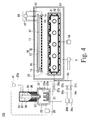
- Fig. 3 shows a perspective view of the vapor deposition apparatus 10b; and Fig. 4 shows a cross sectional view of the vapor deposition apparatus 10b.
- the vapor deposition apparatus 10b has a vacuum chamber 11, a substrate-holding device (substrate holder) 15, a mask-holding device 19, a positioning device 60, an emitting device 50, a switching device 65, and a plurality of feeding devices 20a to 20c (3 units in this embodiment).
- the vapor deposition material in this embodiment is an organic material composed of a mixture of an organic compound (host) as a main component and a coloring agent (dopant) as an additive.
- the respective feeding devices 20a to 20c contain the organic materials having the same colors as those of the colored layer (red, green and blue in this embodiment). These feeding devices 20a to 20c have the same structure, except that colors of organic materials 39 are different. The description below is given by designating the same reference symbol to the same member.
- Each of the feeding devices 20a to 20c has a vessel-shape containing part 32, and a lid 34 is attached at the opening of the vessel.
- the organic materials 39 are respectively contained in each of the containing parts 32.
- the bottom portion of the containing part 32 is in a mortar shape. At approximately center of the bottom of the mortar shape, a through-hole 37 is formed, and the containing part 32 is connected to an evaporation chamber 21 via the through-hole 37.
- a rotary shaft 35 which has a spiral convex portion 36 around thereof, is inserted into the through-hole 37.
- a rotary means 41 rotates the rotary shaft 35 around the center axis thereof, the organicmaterial 39 contained in the containing part 32 moves from the top toward the bottom of the through-hole 37 therein via the groove between the convex portions 36.
- the organic material 39 drops off from the groove immediately below into the evaporation chamber 21.
- the amount of dropping organic material 39 is proportionate to the number of rotations of the rotary shaft 35, if the relationship between the amount of drop and the number of rotations is preliminarily determined, the number of rotations required for dropping the necessary amount of the organic material 39 is predicted from the relationship thereof.
- a hot body 22 is arranged directly beneath the through-hole 37 in the evaporation chamber 21.
- the hot body 22 has a high temperature vessel 22b having an opening larger than the bottom opening of the through-hole 37, and a convex part 22a provided approximately at the center of the bottom of the high temperature vessel 22b.
- the area of the cross-section of the convex part 22a is almost equal to that of the cross section of the rotary shaft 35; and the convex part 22a is positioned at directly beneath the rotary shaft 35.
- the vapor deposition material 39 dropping directly underneath the lower end of the through-hole 37 comes between the convex part 22a and the side wall of the high temperature vessel 22b, so as to surround the convex part 22a resulting from the rotation of the rotary shaft 35.
- a heating means (such as a coil) 25 is wound around the evaporation chamber 21. If an electric power is preliminarily applied to the heating means 25 from a power source 26 and the hot body 22 is induction-heated inside the evaporation chamber 21, the organic material is heated by the hot body 22, and the vapor thereof is generated.
- the vapor deposition material 39 is placed between the convex part 22a and the side wall of the high temperature vessel 22b so as to surround the convex part 22a, the vapor deposition material 39 is uniformly heated, and the vapor of the vapor deposition material 39 is generated in the evaporation chamber 21.
- Each of the feeding devices 20a to 20c is connected to the switching device 65, and the vapor generated in the evaporation chambers 21 is supplied to the switching device 65.
- the switching device 65 has a plurality of pipes 59 and valves 57.
- Each of the pipes 59 is connected to an evaporation chamber 21 of each of the feeding devices 20a to 20c at an end thereof, while the other end of the pipe 59 is connected to the single emitting device 50, and each of the valves 57 is attached between an end and the other end of each of the pipes 59a to 59c.
- the vapor supplied to the switching device 65 is fed to the pipes 59a to 59c connected to the vapor-generated evaporation chamber 21.
- the valves 57a to 57c which are attached to the pipes 59a to 59c are opened, the vapor is supplied into the emitting device 50.
- the valves 57a to 57c are closed, the vapor is not supplied to the emitting device 50.
- the emitting device 50 has a box-shaped vessel 51 and supply pipes 52 arranged in the vessel 51.
- the vapor supplied to the emitting device 50 is fed to the supply pipes 52, and is ejected toward the bottom of the vessel 51 from ejection holes 53 provided on the supply pipes 52, and is then emitted inside the vacuum chamber 11 from emission holes 55 provided at the ceiling of the vessel 51.
- the vacuum chamber 11, the evaporation chambers 21, and the containing parts 32 are connected to the evacuation system 9; and the internal spaces of the vacuum chamber 11, the evaporation chambers 21, and the containing parts 32 sealed in a state of containing the organic material 39 are evacuated to form a vacuum atmosphere in the internal spaces of the evaporation chambers 21, the vacuum chamber 11, the vessel 51, the supply pipes 52, the pipes 59, and the containing parts 32 at a predetermined pressure (for example, 10 -5 Pa).
- a substrate 81 is carried-in to the vacuum chamber 11 while maintaining the vacuum atmosphere.
- Fig. 2 (a) shows a cross-sectional view of the substrate 81, which is carried into the vacuum chamber 11.
- a transparent electrode 82 is formed on the surface thereof; and in another vapor deposition apparatus 10a, an organic thin film 83, such as a charge transporting layer and a charge-injection layer, is preliminarily formed.
- a substrate-holding device 15 and a mask-holding device 19 are arranged inside the vacuum chamber 11.
- the substrate-holding device 15 holds the substrate 81, which is carried into the vacuum chamber 11, in such a manner that the deposited side of the substrate on which the transparent electrode 82 and the organic thin film 83 are formed is faced downward.
- the mask 16 has a plate-shaped shield part 18 and a plurality of openings 17 provided on the shield part 18.
- the mask 16 is carried into the vacuum chamber 11 in advance, and is held by the mask-holding device 19 in such a manner that the openings 17 are exposed.
- the mask 16 used in the present invention is the one to be used for forming colored layers of two or more colors by the single sheet of mask 16.
- the shape and the spacing of regions to form the respective colored layers of the respective colors on the substrate 81 are equal with each region; and the shape and the spacing of the openings 17 of the mask 16 are almost equal to the shape and the spacing of regions to form the respective colored layers of the respective colors.
- a positioning device 60 has a transport means 61 and a monitor (such as a CCD camera) 62.
- the sequential order of color of colored layers to be deposited is preliminarily determined. While the monitor 62 monitors the alignment mark of the mask 16 and the alignment mark of the substrate 81, the transport means 61 moves any one or both of the substrate-holding device 15 and the mask-holding device 19 to align the positioning of the respective openings 17 to the respective regions where the colored layer of the first color is formed on the surface of the substrate 81.
- the substrate 81 held by the substrate-holding device 15 is brought to a position above the emitting device 50, and the mask 16 held by the mask-holding device 19 is then brought to a position between the emitting device 50 and the substrate 81.
- valves 57a to 57c are kept closed.
- the hot body 22 of each of the feeding devices 20a to 20c is heated to a predetermined temperature (for example, 300°C to 350°C), and the temperature is then maintained.
- the film thickness of each colored layer is preliminarily determined, and the amount of organic material 39 necessary to deposit the colored layer with the predetermined thickness is preliminarily grasped.
- valve of the evacuation system connected to the evaporation chamber 21 of the feeding device 20a for the first color is closed; the rotary shaft 35 is rotated by a necessary number of rotations; the necessary amount of the organic material 39 of the first color is dropped onto the hot body 22; and the vapor is generated in the evaporation chamber 21.
- the evacuation of the vacuum chamber 11 is continued while the valve of evacuation system connected to the evaporation chamber 21 is kept closed.
- the valve of evacuation system connected to the evaporation chamber 21 is kept closed.
- the evaporation chamber 21 where the vapor of the first color is generated is connected to the emitting device 50.
- the vapor is brought to pass through the switching device 65 and the emitting device 50, and is emitted into the vacuum chamber 11 via the emission holes 55.
- a colored layer 85a of the first color is formed on predetermined regions.
- the evaporation chamber 21 which generated the vapor of the first color is evacuated in a state of closing the valve 57a while continuing the evacuation of the vacuum chamber 11. Then, the evacuation of the vacuum chamber 11 discharges the vapor of the first color from the emitting device 50 and from the switching device 65 at a portion of the emitting device 50 side, not at the portions of the valves 57a to 57c sides, and the evacuation of the evaporation chamber 21 discharges the vapor of the first color from the evaporation chamber 21 and from the switching device 65 at a portion of the evaporation chamber 21 side, not at the portions of the valves 57a to 57c sides.
- the emitting device 50, the switching device 65, and the evaporation chambers 21 are formed at respectively predetermined pressure, the vapor of the color of the organic material 39 is generated in the evaporation chamber 21 of the feeding device 20b containing the organic material 39 of the second color while the respective valves 57a to 57c are kept closed.
- the openings 17 of the mask 16 are moved from the regions to form the colored layer of the first color on the surface of the substrate 81 to the regions to form the colored layer of the second color thereon. Then, the evaporation chamber 21 which generated the vapor of the organic material 39 of the second color is connected to the emitting device 50. As illustrated in Fig. 2(c) , a colored layer 85b of the second color are deposited at the regions in order to form the colored layer 85b.
- a colored layer 85c of the three or more colors can be formed on the respective predetermined regions on the surface of the substrate 81 ( Fig. 2(d) ).
- the number of the openings 17 is larger than the number of the colored layers of a single color.
- the opening 17 at an edge part of the mask 16 may go into an unnecessary region so as to form the colored layer on the substrate 81.
- a frame 13 is applied to the outer peripheral part of the substrate 81 held by the substrate-holding device 15, and the regions unnecessary to form the colored layer are covered with the frame 13. Accordingly, the vapor does not reach the regions unnecessary to form the colored layer, and the colored layers 85a to 85c are formed only in the predetermined regions.
- the host and the dopant are contained in different containing parts 32 of the feeding devices 20a to 20c, respectively; each of the vapor of host and the vapor of dopant is supplied to the same supply pipe 52 from the feeding device 20a containing the host and from the feeding device 20b containing the dopant; the mixed vapor of the host vapor and the dopant vapor is emitted from the emission holes 55; and then an organic thin film containing both the host and the dopant is deposited.
- the colored layers 85a to 85c are not limited to three colors, and a single color or four or more colors can be applied.
- any one or both of the emitting device 50 and the substrate-holding device 15 are connected to a shaker 58, and any one or both of the emitting device 50 and the substrate-holding device 15 reciprocate or circulate in horizontal plane, in such a state that the substrate 81 and the mask 16 stand still relative to each other, during the period of growth of the colored layer 85a, then the film thickness of the colored layer 85a becomes uniform.
- the direction of relative reciprocating motion of the substrate 81 and the emitting device 50 is not specifically limited. However, for example, when the supply pipe 52 has a plurality of branch pipes arranged at a predetermined spacing therebetween, the substrate 81 and the emitting device 50 are moved relatively in the direction intersecting the branch pipes in the horizontal plane.
- a cooling plate 67 is positioned around the vessel 51 with a distance therebetween, the mask 16 is not heated so that the thermal expansion of the mask 16 does not occur, thereby increasing the deposition accuracy of the colored layers 85a to 85c.
- cooling plate 67 If openings are formed on the cooling plate 67 at the positions above the emission holes 55 so as to expose the emission holes 55 and the area of the opening of the cooling plate 67 is sufficiently large to avoid contact with vapor emitted from the emission hole 55, the vapor is not deposited on the cooling plate 67.
- the heating of the hot body 22 is not limited to induction heating, and thermal conduction from a heating means may be used. Furthermore, the organic material 39 may be directly heated by irradiating laser beam to the organic material 39.
- the inside of the evaporation chambers 21 may be evacuated, not by connecting the evaporation chambers 21 directly to the evacuation system, but by connecting the evaporation chambers 21 to the emitting device 50 and evacuating the vacuum chamber 11.
- the evacuation of the evaporation chamber 21 can be stopped by shutting-off the evaporation chambers 21 from the emitting device 50 by using the switching device 65.
- the shape and the installation place of the hot body 22 are not specifically limited, and the hot body 22 may be placed obliquely downwardly below the through-hole 37 if only the organic material can enter the hot body 22.
- the present invention is not limited to the case of using the mask 16.
- the mask is not placed between the substrate 81 and the emitting device 50, and the colored layers 85a to 85c of three or more colors may be laminated on the surface of the substrate 81 in order to form an organic film for white light.
Landscapes
- Chemical & Material Sciences (AREA)
- Engineering & Computer Science (AREA)
- Chemical Kinetics & Catalysis (AREA)
- Materials Engineering (AREA)
- Mechanical Engineering (AREA)
- Metallurgy (AREA)
- Organic Chemistry (AREA)
- Manufacturing & Machinery (AREA)
- Electroluminescent Light Sources (AREA)
- Physical Vapour Deposition (AREA)
Abstract
Description
- The present invention generally relates to a vapor deposition apparatus.
- Organic EL element is one of the most watched display elements in recent years and has excellent characteristics of high luminance and high response rate. The organic EL element has a glass substrate on which a light-emitting region is formed in order to develop three different colors: red, green and blue. The light-emitting region is formed by laminating an anode electrode film, a hole-injecting layer, a hole-transporting layer, a light-emitting layer, an electron-transporting layer, an electron-injecting layer, and a cathode electrode film in this order so as to develop color in red, green or blue by the respective coloring agents added to the light-emitting layer.
- Each of the hole-transporting layer, the light-emitting layer, the electron-transporting layer, or the like is generally made of an organic material. For the deposition of a film of such an organic material, a vapor deposition apparatus is widely used.
- A
reference numeral 203 inFig. 5 denotes a vapor deposition apparatus in the conventional art; and avapor deposition vessel 212 is disposed inside avacuum chamber 211. Thevapor deposition vessel 212 has avessel body 221; and the upper portion of thevessel body 221 is closed by alid part 222 having one ormore emission holes 224 formed therein. - Inside the
vapor deposition vessel 212, a powder organicvapor deposition material 200 is disposed. - A heating means 223 is located at side faces and a bottom face of the
vapor deposition vessel 212. When thevacuum chamber 211 is evacuated and the heating means 223 generates heat, thevapor deposition vessel 212 increases the temperature thereof; and thus, the organicvapor deposition material 200 in thevapor deposition vessel 212 is heated. - When the organic
vapor deposition material 200 is heated to at or above the evaporation temperature thereof, thevapor deposition vessel 212 is filled with the vapor of the organic material, and the vapor is emitted into thevacuum chamber 211 via theemission holes 224. - A
holder 210 is provided above theemission holes 224. When asubstrate 205 is held by theholder 210, the organic material vapor emitted from theemission holes 224 reaches the surface of thesubstrate 205, thereby forming an organic thin film such as a hole-injecting layer, a hole-transporting layer, and a light-emitting layer thereon. - For manufacturing a color display organic EL device, normally the light-emitting layer is formed by depositing the respective colored layers of two or more colors in the respective different regions. In this case, since the colored layer is to be formed in the respective predetermined regions, the deposition is performed after disposing, between the
vapor deposition vessel 212 and thesubstrate 205, amask 214 having openings which have almost the same shape and spacing as those of the regions. - In the conventional art, after the film formation of the first color of the colored layer is completed, the
mask 214 is removed from thesubstrate 205. Then thesubstrate 205 is transported to a different vapor deposition apparatus, where a new mask is attached, and the film of the second color or more of the colored layer is formed. - However, since, in the above-described method, during a period of depositing a single light-emitting layer, the
substrate 205 has to be carried-in to and carried-out from the vapor deposition apparatus several times and the transportation distance of thesubstrate 205 increases, which results in dust likely to be generated. Once dust is generated, the dust enters the light-emitting layer and the thin film deposited in the succeeding step of forming the light-emitting layer, which causes contamination of the organic EL device. - Patent Document 1: Japanese Patent Laid-OpenNo.
10-204624 - Patent Document 2: Japanese Patent Laid-Open No.
2006-307239 - Patent Document 3: Japanese Patent Laid-Open No.
2003-293121 - Patent Document 3: Japanese Patent Laid-Open No.
2005-163156 - The present invention is directed to solve the above problems, and an object of the present invention is to provide a vapor deposition apparatus which enables the formation of a film of a light-emitting layer without causing contamination.
- In order to solve the above problems, the present invention is directed to a vapor deposition apparatus having a vacuum chamber, a substrate-holding device located inside the vacuum chamber for holding a substrate, a feeding device containing an organic material therein for generating a vapor of the organic material, an emitting device located at a position facing the substrate for emitting, to the inside of the vacuum chamber, the vapor of the organic material which is generated from the feeding device, a mask having a plurality of openings formed therein and located inside the vacuum chamber, and a mask-holding device holding the mask at a position between the substrate and the emitting device. The present invention is directed to the vapor deposition apparatus, in which the vapor emitted from the emitting device passes through the openings of the mask and reaches the substrate having each of a plurality of the feeding devices connected to the emitting device, a positioning device for positioning the substrate held by the substrate-holding device with the mask held by the mask-holding device, and a switching device for connecting the desired feeding device among a plurality of the feeding devices to the emitting device.
- The present invention also provides a vapor deposition apparatus having a vacuum chamber, a substrate-holding device located inside the vacuum chamber for holding a substrate, a feeding device containing an organic material therein for generating a vapor of the organic material, and an emitting device located at a position facing the substrate for emitting , to the inside of the vacuum chamber, the vapor of the organic material which is generated from the feeding device. The vapor deposition apparatus, in which the vapor emitted from the emitting device reaches the substrate, further includes each of a plurality of the feeding devices connected to the emitting device, and a switching device for connecting the desired feeding device among a plurality of the feeding devices to the emitting device.
- The present invention further provides a vapor deposition apparatus, wherein the respective feeding devices contain the organic material having a color different from each other.
- The present invention still further provides a vapor deposition apparatus, in which each of the feeding devices includes a containing part containing the organic material, a through-hole formed at a bottom part of the containing part, an evaporation chamber connected to the containing part via the through-hole, a rotary shaft inserted into the through-hole, and a rotary means for rotating the rotary shaft around a center axis thereof, and wherein the rotary shaft has a spiral convex portion formed at the periphery thereof, and the rotation of the rotary shaft moves the organic material from the containing part toward the evaporation chamber through a groove between the convex portions.
- Without carrying in and carrying out the substrate to and from the vacuum chamber, the different organic thin films can be formed at different places on the substrate within the same vacuum chamber. Compared to the conventional art, the transport distance of the substrate during deposition is small so that no dust is generated inside the vacuum chamber, which causes no contamination in the organic EL device.
-
-
Fig. 1 shows a schematic plan view illustrating an example of a film-forming apparatus. -
Figs. 2 (a) to 2 (b) show cross sectional views illustrating the process of depositing colored layers. -
Fig. 3 shows a schematic perspective view of a vapor deposition apparatus of the present invention. -
Fig. 4 shows a cross-sectional view of the vapor deposition apparatus of the present invention. -
Fig. 5 shows a cross-sectional view illustrating a vapor deposition apparatus of the conventional art. -
- 10a to 10c
- vapor deposition apparatus
- 11
- vacuum chamber
- 15
- substrate-holding device
- 16
- mask
- 20a to 20c
- feeding device
- 39
- organic material
- 50
- emitting device
- 60
- positioning device
- A
reference symbol 1 inFig. 1 shows an example of a film-forming apparatus. - The film-forming
apparatus 1 has atransporting chamber 2. A carry-inchamber 3a, a carry-out chamber 3b, apretreatment chamber 4, one or morevapor deposition apparatuses 10a to 10c, a sputtering apparatus 8, and a mask-storing chamber 7, respectively, are connected to thetransporting chamber 2. - A
transfer robot 5 is positioned inside the transportingchamber 2. Anevacuation system 9 forms a vacuum atmosphere inside of each of the transportingchamber 2, the carry-inchamber 3a, the carry-outchamber 3b, thepretreatment chamber 4, thevapor deposition apparatuses 10a to 10c, and the sputtering apparatus 8. The substrate carried into the carry-inchamber 3a is transported by thetransfer robot 5 from the carry-inchamber 3a to thepretreatment chamber 4 in the vacuum atmosphere to undergo the pretreatment of cleaning, heating, or the like. After that, the substrate is transported through each of thevapor deposition apparatuses 10a to 10c successively, and organic thin films, such as a charge transfer layer, a light-emitting layer, and an electron transfer layer, are laminated on the substrate. Then, an upper electrode film is formed on the organic thin film by the sputtering apparatus 8. Finally the substrate is carried out from the carry-outchamber 3b. - Among the organic thin films, the light-emitting layer is composed of colored layers having two or more different colors being respectively formed at the corresponding regions on the surface of the substrate.
- A
reference symbol 10b inFig. 1 denotes a vapor deposition apparatus of the present invention used for depositing the light-emitting layer. -
Fig. 3 shows a perspective view of thevapor deposition apparatus 10b; andFig. 4 shows a cross sectional view of thevapor deposition apparatus 10b. Thevapor deposition apparatus 10b has avacuum chamber 11, a substrate-holding device (substrate holder) 15, a mask-holdingdevice 19, apositioning device 60, an emittingdevice 50, aswitching device 65, and a plurality offeeding devices 20a to 20c (3 units in this embodiment). - The vapor deposition material in this embodiment is an organic material composed of a mixture of an organic compound (host) as a main component and a coloring agent (dopant) as an additive. The
respective feeding devices 20a to 20c contain the organic materials having the same colors as those of the colored layer (red, green and blue in this embodiment). Thesefeeding devices 20a to 20c have the same structure, except that colors oforganic materials 39 are different. The description below is given by designating the same reference symbol to the same member. - Each of the
feeding devices 20a to 20c has a vessel-shape containing part 32, and alid 34 is attached at the opening of the vessel. Theorganic materials 39 are respectively contained in each of the containingparts 32. - The bottom portion of the containing
part 32 is in a mortar shape. At approximately center of the bottom of the mortar shape, a through-hole 37 is formed, and the containingpart 32 is connected to anevaporation chamber 21 via the through-hole 37. - A
rotary shaft 35, which has a spiralconvex portion 36 around thereof, is inserted into the through-hole 37. When a rotary means 41 rotates therotary shaft 35 around the center axis thereof, theorganicmaterial 39 contained in the containingpart 32 moves from the top toward the bottom of the through-hole 37 therein via the groove between theconvex portions 36. Once theorganic material 39 reaches the lower end of the through-hole 37, theorganic material 39 drops off from the groove immediately below into theevaporation chamber 21. - Since the amount of dropping
organic material 39 is proportionate to the number of rotations of therotary shaft 35, if the relationship between the amount of drop and the number of rotations is preliminarily determined, the number of rotations required for dropping the necessary amount of theorganic material 39 is predicted from the relationship thereof. - A
hot body 22 is arranged directly beneath the through-hole 37 in theevaporation chamber 21. - The
hot body 22 has a high temperature vessel 22b having an opening larger than the bottom opening of the through-hole 37, and a convex part 22a provided approximately at the center of the bottom of the high temperature vessel 22b. - The area of the cross-section of the convex part 22a is almost equal to that of the cross section of the
rotary shaft 35; and the convex part 22a is positioned at directly beneath therotary shaft 35. - Accordingly, the
vapor deposition material 39 dropping directly underneath the lower end of the through-hole 37 comes between the convex part 22a and the side wall of the high temperature vessel 22b, so as to surround the convex part 22a resulting from the rotation of therotary shaft 35. - A heating means (such as a coil) 25 is wound around the
evaporation chamber 21. If an electric power is preliminarily applied to the heating means 25 from apower source 26 and thehot body 22 is induction-heated inside theevaporation chamber 21, the organic material is heated by thehot body 22, and the vapor thereof is generated. - As described above, since the
vapor deposition material 39 is placed between the convex part 22a and the side wall of the high temperature vessel 22b so as to surround the convex part 22a, thevapor deposition material 39 is uniformly heated, and the vapor of thevapor deposition material 39 is generated in theevaporation chamber 21. - Each of the
feeding devices 20a to 20c is connected to theswitching device 65, and the vapor generated in theevaporation chambers 21 is supplied to theswitching device 65. - The switching
device 65 has a plurality of pipes 59 and valves 57. Each of the pipes 59 is connected to anevaporation chamber 21 of each of thefeeding devices 20a to 20c at an end thereof, while the other end of the pipe 59 is connected to the single emittingdevice 50, and each of the valves 57 is attached between an end and the other end of each of thepipes 59a to 59c. - The vapor supplied to the
switching device 65 is fed to thepipes 59a to 59c connected to the vapor-generatedevaporation chamber 21. When thevalves 57a to 57c which are attached to thepipes 59a to 59c are opened, the vapor is supplied into the emittingdevice 50. On the other hand, when thevalves 57a to 57c are closed, the vapor is not supplied to the emittingdevice 50. - The emitting
device 50 has a box-shapedvessel 51 andsupply pipes 52 arranged in thevessel 51. The vapor supplied to the emittingdevice 50 is fed to thesupply pipes 52, and is ejected toward the bottom of thevessel 51 from ejection holes 53 provided on thesupply pipes 52, and is then emitted inside thevacuum chamber 11 fromemission holes 55 provided at the ceiling of thevessel 51. - Next, the step of depositing the light-emitting layer using the
vapor deposition apparatus 10b is described. - The
vacuum chamber 11, theevaporation chambers 21, and the containingparts 32 are connected to theevacuation system 9; and the internal spaces of thevacuum chamber 11, theevaporation chambers 21, and the containingparts 32 sealed in a state of containing theorganic material 39 are evacuated to form a vacuum atmosphere in the internal spaces of theevaporation chambers 21, thevacuum chamber 11, thevessel 51, thesupply pipes 52, the pipes 59, and the containingparts 32 at a predetermined pressure (for example, 10-5Pa). Asubstrate 81 is carried-in to thevacuum chamber 11 while maintaining the vacuum atmosphere. -
Fig. 2 (a) shows a cross-sectional view of thesubstrate 81, which is carried into thevacuum chamber 11. Before thesubstrate 81 is carried into the film-formingapparatus 1, atransparent electrode 82 is formed on the surface thereof; and in anothervapor deposition apparatus 10a, an organicthin film 83, such as a charge transporting layer and a charge-injection layer, is preliminarily formed. - A substrate-holding
device 15 and a mask-holdingdevice 19 are arranged inside thevacuum chamber 11. The substrate-holdingdevice 15 holds thesubstrate 81, which is carried into thevacuum chamber 11, in such a manner that the deposited side of the substrate on which thetransparent electrode 82 and the organicthin film 83 are formed is faced downward. - The
mask 16 has a plate-shapedshield part 18 and a plurality ofopenings 17 provided on theshield part 18. Themask 16 is carried into thevacuum chamber 11 in advance, and is held by the mask-holdingdevice 19 in such a manner that theopenings 17 are exposed. - The
mask 16 used in the present invention is the one to be used for forming colored layers of two or more colors by the single sheet ofmask 16. - The shape and the spacing of regions to form the respective colored layers of the respective colors on the
substrate 81 are equal with each region; and the shape and the spacing of theopenings 17 of themask 16 are almost equal to the shape and the spacing of regions to form the respective colored layers of the respective colors. - A
positioning device 60 has a transport means 61 and a monitor (such as a CCD camera) 62. The sequential order of color of colored layers to be deposited is preliminarily determined. While themonitor 62 monitors the alignment mark of themask 16 and the alignment mark of thesubstrate 81, the transport means 61 moves any one or both of the substrate-holdingdevice 15 and the mask-holdingdevice 19 to align the positioning of therespective openings 17 to the respective regions where the colored layer of the first color is formed on the surface of thesubstrate 81. - When the
substrate 81 and themask 16, which are aligned with each other, are maintained in a relatively stand still state, thesubstrate 81 held by the substrate-holdingdevice 15 is brought to a position above the emittingdevice 50, and themask 16 held by the mask-holdingdevice 19 is then brought to a position between the emittingdevice 50 and thesubstrate 81. - The
valves 57a to 57c are kept closed. Thehot body 22 of each of thefeeding devices 20a to 20c is heated to a predetermined temperature (for example, 300°C to 350°C), and the temperature is then maintained. - The film thickness of each colored layer is preliminarily determined, and the amount of
organic material 39 necessary to deposit the colored layer with the predetermined thickness is preliminarily grasped. - When the
respective valves 57a to 57c are closed and thevacuum chamber 11 is evacuated, the valve of the evacuation system connected to theevaporation chamber 21 of thefeeding device 20a for the first color is closed; therotary shaft 35 is rotated by a necessary number of rotations; the necessary amount of theorganic material 39 of the first color is dropped onto thehot body 22; and the vapor is generated in theevaporation chamber 21. - When the internal pressure of the
evaporation chamber 21 reaches a predetermined pressure, the evacuation of thevacuum chamber 11 is continued while the valve of evacuation system connected to theevaporation chamber 21 is kept closed. Thus, whileother evaporation chambers 21 are shut-off from the emittingdevice 50, only theevaporation chamber 21 where the vapor of the first color is generated is connected to the emittingdevice 50. Using difference in pressure, the vapor is brought to pass through the switchingdevice 65 and the emittingdevice 50, and is emitted into thevacuum chamber 11 via the emission holes 55. - In this step, since the
evaporation chambers 21 generating vapors of other colors are shut-off from the emittingdevice 50, the vapors are not mixed with each other, and only the vapor of the first color passes through theopenings 17 of themask 16. As a result, as illustrated inFig. 2(b) , acolored layer 85a of the first color is formed on predetermined regions. - When a predetermined period of time has passed from dropping the
organic material 39 of the first color onto thehot body 22, or when the internal pressure of theevaporation chamber 21 which generates the vapor of theorganic material 39 of the first color reaches or is below the predetermined pressure, the deposition of thecolored layer 85a of the first color is judged to be completed. - After completing the deposition of the
colored layer 85a of the first color, theevaporation chamber 21 which generated the vapor of the first color is evacuated in a state of closing thevalve 57a while continuing the evacuation of thevacuum chamber 11. Then, the evacuation of thevacuum chamber 11 discharges the vapor of the first color from the emittingdevice 50 and from the switchingdevice 65 at a portion of the emittingdevice 50 side, not at the portions of thevalves 57a to 57c sides, and the evacuation of theevaporation chamber 21 discharges the vapor of the first color from theevaporation chamber 21 and from the switchingdevice 65 at a portion of theevaporation chamber 21 side, not at the portions of thevalves 57a to 57c sides. - When the vacuum atmospheres in the
vacuum chamber 11, the emittingdevice 50, the switchingdevice 65, and theevaporation chambers 21 are formed at respectively predetermined pressure, the vapor of the color of theorganic material 39 is generated in theevaporation chamber 21 of thefeeding device 20b containing theorganic material 39 of the second color while therespective valves 57a to 57c are kept closed. - The
openings 17 of themask 16 are moved from the regions to form the colored layer of the first color on the surface of thesubstrate 81 to the regions to form the colored layer of the second color thereon. Then, theevaporation chamber 21 which generated the vapor of theorganic material 39 of the second color is connected to the emittingdevice 50. As illustrated inFig. 2(c) , acolored layer 85b of the second color are deposited at the regions in order to form thecolored layer 85b. - After the deposition of the
colored layer 85b of the second color is completed, by repeating the discharge of vapor, the positioning, and the deposition of colored layer, acolored layer 85c of the three or more colors can be formed on the respective predetermined regions on the surface of the substrate 81 (Fig. 2(d) ). - According to the present invention, since the
colored layers 85a to 85c of two or more colors are formed by changing the positions of the single sheet of themask 16, the number of theopenings 17 is larger than the number of the colored layers of a single color. Thus, theopening 17 at an edge part of themask 16 may go into an unnecessary region so as to form the colored layer on thesubstrate 81. - In this embodiment, a
frame 13 is applied to the outer peripheral part of thesubstrate 81 held by the substrate-holdingdevice 15, and the regions unnecessary to form the colored layer are covered with theframe 13. Accordingly, the vapor does not reach the regions unnecessary to form the colored layer, and thecolored layers 85a to 85c are formed only in the predetermined regions. - The above description is given to the case where the host and the dopant are contained in the same containing
part 32 of each of thefeeding devices 20a to 20c. The present invention is, however, not limited thereto. - For example, it may be that the host and the dopant are contained in different containing
parts 32 of thefeeding devices 20a to 20c, respectively; each of the vapor of host and the vapor of dopant is supplied to thesame supply pipe 52 from thefeeding device 20a containing the host and from thefeeding device 20b containing the dopant; the mixed vapor of the host vapor and the dopant vapor is emitted from the emission holes 55; and then an organic thin film containing both the host and the dopant is deposited. - The
colored layers 85a to 85c are not limited to three colors, and a single color or four or more colors can be applied. - When any one or both of the emitting
device 50 and the substrate-holdingdevice 15 are connected to ashaker 58, and any one or both of the emittingdevice 50 and the substrate-holdingdevice 15 reciprocate or circulate in horizontal plane, in such a state that thesubstrate 81 and themask 16 stand still relative to each other, during the period of growth of thecolored layer 85a, then the film thickness of thecolored layer 85a becomes uniform. - The direction of relative reciprocating motion of the
substrate 81 and the emittingdevice 50 is not specifically limited. However, for example, when thesupply pipe 52 has a plurality of branch pipes arranged at a predetermined spacing therebetween, thesubstrate 81 and the emittingdevice 50 are moved relatively in the direction intersecting the branch pipes in the horizontal plane. - If a
cooling plate 67 is positioned around thevessel 51 with a distance therebetween, themask 16 is not heated so that the thermal expansion of themask 16 does not occur, thereby increasing the deposition accuracy of thecolored layers 85a to 85c. - If openings are formed on the
cooling plate 67 at the positions above the emission holes 55 so as to expose the emission holes 55 and the area of the opening of the coolingplate 67 is sufficiently large to avoid contact with vapor emitted from theemission hole 55, the vapor is not deposited on thecooling plate 67. - The heating of the
hot body 22 is not limited to induction heating, and thermal conduction from a heating means may be used. Furthermore, theorganic material 39 may be directly heated by irradiating laser beam to theorganic material 39. - Alternatively, the inside of the
evaporation chambers 21 may be evacuated, not by connecting theevaporation chambers 21 directly to the evacuation system, but by connecting theevaporation chambers 21 to the emittingdevice 50 and evacuating thevacuum chamber 11. In this case, the evacuation of theevaporation chamber 21 can be stopped by shutting-off theevaporation chambers 21 from the emittingdevice 50 by using theswitching device 65. - The shape and the installation place of the
hot body 22 are not specifically limited, and thehot body 22 may be placed obliquely downwardly below the through-hole 37 if only the organic material can enter thehot body 22. - In addition, the present invention is not limited to the case of using the
mask 16. For example, it may be that the mask is not placed between thesubstrate 81 and the emittingdevice 50, and thecolored layers 85a to 85c of three or more colors may be laminated on the surface of thesubstrate 81 in order to form an organic film for white light.
Claims (6)
- A vapor deposition apparatus having a vacuum chamber, a substrate-holding device located inside the vacuum chamber for holding a substrate, a feeding device containing an organic material therein for generating a vapor of the organic material, an emitting device located at a position facing the substrate for emitting, to the inside of the vacuum chamber, the vapor of the organic material which is generated from the feeding device, a mask having a plurality of openings formed therein and located inside the vacuum chamber, and a mask-holding device holding the mask at a position between the substrate and the emitting device, the vapor deposition apparatus in which the vapor emitted from the emitting device passes through the openings of the mask and reaches the substrate, characterized by each of a plurality of the feeding devices connected to the emitting device, a positioning device for positioning the substrate held by the substrate-holding device with the mask held by the mask-holding device, and a switching device for connecting the desired feeding device among a plurality of the feeding devices to the emitting device.
- The vapor deposition apparatus according to claim 1, characterized in that the respective feeding devices contain the organic material having a color different from each other.
- The vapor deposition apparatus according to claim 1, characterized in that each of the feeding devices has a containing part containing the organic material, a through-hole formed at a bottom part of the containing part, an evaporation chamber connected to the containing part via the through-hole, a rotary shaft inserted into the through-hole, and a rotary means for rotating the rotary shaft around a center axis thereof, wherein the rotary shaft has a spiral convex portion formed at the periphery thereof, and the rotation of the rotary shaft moves the organic material from the containing part toward the evaporation chamber through a groove between the convex portions.
- A vapor deposition apparatus having a vacuum chamber, a substrate-holding device located inside the vacuum chamber for holding a substrate, a feeding device containing an organic material therein for generating a vapor of the organic material, and an emitting device located at a position facing the substrate for emitting, to the inside of the vacuum chamber, the vapor of the organic material which is generated from the feeding device, the vapor deposition apparatus, in which the vapor emitted from the emitting device reaches the substrate, characterized by each of a plurality of the feeding devices connected to the emitting device, and a switching device for connecting the desired feeding device among a plurality of the feeding devices to the emitting device.
- The vapor deposition apparatus according to claim 4, characterized in that the respective feeding devices contain the organic material having a color different from each other.
- The vapor deposition apparatus according to claim 4, characterized in that each of the feeding devices has a containing part containing the organic material, a through-hole formed at a bottom part of the containing part, an evaporation chamber connected to the containing part via the through-hole, a rotary shaft inserted into the through-hole, and a rotary means for rotating the rotary shaft around a center axis thereof, wherein the rotary shaft has a spiral convex portion formed at the periphery thereof, and the rotation of the rotary shaft moves the organic material from the containing part toward the evaporation chamber through a groove between the convex portions.
Applications Claiming Priority (3)
| Application Number | Priority Date | Filing Date | Title |
|---|---|---|---|
| JP2007234441 | 2007-09-10 | ||
| JP2007259099 | 2007-10-02 | ||
| PCT/JP2008/065982 WO2009034915A1 (en) | 2007-09-10 | 2008-09-04 | Evaporation apparatus |
Publications (2)
| Publication Number | Publication Date |
|---|---|
| EP2190264A1 true EP2190264A1 (en) | 2010-05-26 |
| EP2190264A4 EP2190264A4 (en) | 2011-11-23 |
Family
ID=40451924
Family Applications (1)
| Application Number | Title | Priority Date | Filing Date |
|---|---|---|---|
| EP08831052A Withdrawn EP2190264A4 (en) | 2007-09-10 | 2008-09-04 | EVAPORATION APPARATUS |
Country Status (7)
| Country | Link |
|---|---|
| US (1) | US20100170439A1 (en) |
| EP (1) | EP2190264A4 (en) |
| JP (1) | JP5282038B2 (en) |
| KR (1) | KR101167546B1 (en) |
| CN (1) | CN101803459A (en) |
| TW (1) | TWI412616B (en) |
| WO (1) | WO2009034915A1 (en) |
Families Citing this family (36)
| Publication number | Priority date | Publication date | Assignee | Title |
|---|---|---|---|---|
| US8349143B2 (en) * | 2008-12-30 | 2013-01-08 | Intermolecular, Inc. | Shadow masks for patterned deposition on substrates |
| JP5328726B2 (en) | 2009-08-25 | 2013-10-30 | 三星ディスプレイ株式會社 | Thin film deposition apparatus and organic light emitting display device manufacturing method using the same |
| JP5677785B2 (en) | 2009-08-27 | 2015-02-25 | 三星ディスプレイ株式會社Samsung Display Co.,Ltd. | Thin film deposition apparatus and organic light emitting display device manufacturing method using the same |
| US8876975B2 (en) | 2009-10-19 | 2014-11-04 | Samsung Display Co., Ltd. | Thin film deposition apparatus |
| KR101146982B1 (en) * | 2009-11-20 | 2012-05-22 | 삼성모바일디스플레이주식회사 | Aapparatus for thin layer deposition and method of manufacturing organic light emitting display apparatus |
| KR101174874B1 (en) * | 2010-01-06 | 2012-08-17 | 삼성디스플레이 주식회사 | Deposition source, apparatus for thin layer deposition and method of manufacturing organic light emitting display apparatus |
| KR101084184B1 (en) | 2010-01-11 | 2011-11-17 | 삼성모바일디스플레이주식회사 | Thin film deposition apparatus |
| KR101174875B1 (en) | 2010-01-14 | 2012-08-17 | 삼성디스플레이 주식회사 | Apparatus for thin layer deposition, method for manufacturing of organic light emitting display apparatus using the same, and organic light emitting display apparatus manufactured by the method |
| KR101193186B1 (en) | 2010-02-01 | 2012-10-19 | 삼성디스플레이 주식회사 | Apparatus for thin layer deposition, method for manufacturing of organic light emitting display apparatus using the same, and organic light emitting display apparatus manufactured by the method |
| KR101156441B1 (en) | 2010-03-11 | 2012-06-18 | 삼성모바일디스플레이주식회사 | Apparatus for thin layer deposition |
| KR101202348B1 (en) | 2010-04-06 | 2012-11-16 | 삼성디스플레이 주식회사 | Apparatus for thin layer deposition and method for manufacturing of organic light emitting display apparatus using the same |
| US8894458B2 (en) | 2010-04-28 | 2014-11-25 | Samsung Display Co., Ltd. | Thin film deposition apparatus, method of manufacturing organic light-emitting display device by using the apparatus, and organic light-emitting display device manufactured by using the method |
| JP5634522B2 (en) * | 2010-09-22 | 2014-12-03 | 株式会社アルバック | Vacuum processing apparatus and organic thin film forming method |
| KR101723506B1 (en) | 2010-10-22 | 2017-04-19 | 삼성디스플레이 주식회사 | Apparatus for organic layer deposition and method for manufacturing of organic light emitting display apparatus using the same |
| KR101738531B1 (en) | 2010-10-22 | 2017-05-23 | 삼성디스플레이 주식회사 | Method for manufacturing of organic light emitting display apparatus, and organic light emitting display apparatus manufactured by the method |
| KR20120045865A (en) | 2010-11-01 | 2012-05-09 | 삼성모바일디스플레이주식회사 | Apparatus for organic layer deposition |
| KR20120065789A (en) | 2010-12-13 | 2012-06-21 | 삼성모바일디스플레이주식회사 | Apparatus for organic layer deposition |
| US9267203B2 (en) | 2010-12-13 | 2016-02-23 | Posco | Continuous coating apparatus |
| KR101760897B1 (en) | 2011-01-12 | 2017-07-25 | 삼성디스플레이 주식회사 | Deposition source and apparatus for organic layer deposition having the same |
| CN103328681B (en) * | 2011-01-20 | 2015-09-23 | 夏普株式会社 | Crucible and evaporation coating device |
| KR101852517B1 (en) | 2011-05-25 | 2018-04-27 | 삼성디스플레이 주식회사 | Apparatus for organic layer deposition and method for manufacturing of organic light emitting display apparatus using the same |
| KR101840654B1 (en) | 2011-05-25 | 2018-03-22 | 삼성디스플레이 주식회사 | Apparatus for organic layer deposition and method for manufacturing of organic light emitting display apparatus using the same |
| KR101857249B1 (en) | 2011-05-27 | 2018-05-14 | 삼성디스플레이 주식회사 | Patterning slit sheet assembly, apparatus for organic layer deposition, method for manufacturing organic light emitting display apparatus and organic light emitting display apparatus |
| KR101826068B1 (en) | 2011-07-04 | 2018-02-07 | 삼성디스플레이 주식회사 | Apparatus for thin layer deposition |
| KR20130015144A (en) | 2011-08-02 | 2013-02-13 | 삼성디스플레이 주식회사 | Deposition source, apparatus for organic layer deposition and method for manufacturing of organic light emitting display apparatus using the same |
| KR102048051B1 (en) * | 2012-09-04 | 2019-11-25 | 삼성디스플레이 주식회사 | Mask assembly for testing deposition condition and deposition apparatus having the same |
| KR101994838B1 (en) | 2012-09-24 | 2019-10-01 | 삼성디스플레이 주식회사 | Apparatus for organic layer deposition, method for manufacturing of organic light emitting display apparatus using the same, and organic light emitting display apparatus manufactured by the method |
| CN103305798B (en) * | 2013-05-21 | 2015-08-26 | 上海和辉光电有限公司 | Evaporation coating device and the evaporation process utilizing this evaporation coating device to carry out |
| CN103305794B (en) * | 2013-06-09 | 2016-03-02 | 京东方科技集团股份有限公司 | A kind of organic film plating device and method |
| WO2014208789A1 (en) * | 2013-06-25 | 2014-12-31 | 에스엔유 프리시젼 주식회사 | Thin film deposition device provided with supply unit |
| CN103741097B (en) * | 2013-12-30 | 2016-02-03 | 深圳市华星光电技术有限公司 | Vacuum deposition apparatus |
| WO2017061481A1 (en) * | 2015-10-06 | 2017-04-13 | 株式会社アルバック | Material supply device and vapor deposition apparatus |
| CN109952388A (en) * | 2017-02-21 | 2019-06-28 | 株式会社爱发科 | Manufacturing equipment of vaporizer and element structure |
| CN109055892B (en) * | 2018-07-27 | 2020-01-10 | 云谷(固安)科技有限公司 | Mask plate and evaporation device |
| US11842907B2 (en) | 2020-07-08 | 2023-12-12 | Applied Materials, Inc. | Spot heating by moving a beam with horizontal rotary motion |
| KR20240154902A (en) | 2023-04-19 | 2024-10-28 | 삼성전자주식회사 | Solder reflow apparatus and method of manufacturing an electronic device |
Family Cites Families (12)
| Publication number | Priority date | Publication date | Assignee | Title |
|---|---|---|---|---|
| US2800252A (en) * | 1954-03-17 | 1957-07-23 | Eugene A Wahl | Powder-feeding apparatus |
| DE3530106A1 (en) * | 1985-08-23 | 1987-02-26 | Kempten Elektroschmelz Gmbh | VAPORIZATION MATERIAL FOR VAPORIZING INORGANIC COMPOUNDS BY MEANS OF A PHOTON-GENERATING RADIATION HEATING SOURCE IN CONTINUOUSLY OPERATED VACUUM VACUUM DEVICES |
| JP2002030418A (en) * | 2000-07-13 | 2002-01-31 | Denso Corp | Vapor deposition equipment |
| US20030151118A1 (en) * | 2002-02-14 | 2003-08-14 | 3M Innovative Properties Company | Aperture masks for circuit fabrication |
| US6749906B2 (en) * | 2002-04-25 | 2004-06-15 | Eastman Kodak Company | Thermal physical vapor deposition apparatus with detachable vapor source(s) and method |
| JP2003347047A (en) * | 2002-05-28 | 2003-12-05 | Sony Corp | Organic film forming equipment |
| JP4510609B2 (en) * | 2004-12-21 | 2010-07-28 | 株式会社アルバック | Substrate and mask alignment method, organic thin film deposition method, and alignment apparatus |
| US7625601B2 (en) * | 2005-02-04 | 2009-12-01 | Eastman Kodak Company | Controllably feeding organic material in making OLEDs |
| JP4911555B2 (en) * | 2005-04-07 | 2012-04-04 | 国立大学法人東北大学 | Film forming apparatus and film forming method |
| JP4535926B2 (en) * | 2005-04-26 | 2010-09-01 | 日立造船株式会社 | Vapor deposition material evaporation equipment |
| JP4789551B2 (en) * | 2005-09-06 | 2011-10-12 | 株式会社半導体エネルギー研究所 | Organic EL film forming equipment |
| JP5568729B2 (en) * | 2005-09-06 | 2014-08-13 | 国立大学法人東北大学 | Film forming apparatus and film forming method |
-
2008
- 2008-09-04 WO PCT/JP2008/065982 patent/WO2009034915A1/en not_active Ceased
- 2008-09-04 EP EP08831052A patent/EP2190264A4/en not_active Withdrawn
- 2008-09-04 KR KR1020107004773A patent/KR101167546B1/en active Active
- 2008-09-04 CN CN200880107079A patent/CN101803459A/en active Pending
- 2008-09-04 JP JP2009532157A patent/JP5282038B2/en active Active
- 2008-09-09 TW TW097134564A patent/TWI412616B/en active
-
2010
- 2010-03-05 US US12/718,350 patent/US20100170439A1/en not_active Abandoned
Also Published As
| Publication number | Publication date |
|---|---|
| TWI412616B (en) | 2013-10-21 |
| EP2190264A4 (en) | 2011-11-23 |
| US20100170439A1 (en) | 2010-07-08 |
| WO2009034915A1 (en) | 2009-03-19 |
| TW200918680A (en) | 2009-05-01 |
| KR101167546B1 (en) | 2012-07-20 |
| CN101803459A (en) | 2010-08-11 |
| JPWO2009034915A1 (en) | 2010-12-24 |
| KR20100040952A (en) | 2010-04-21 |
| JP5282038B2 (en) | 2013-09-04 |
Similar Documents
| Publication | Publication Date | Title |
|---|---|---|
| US20100170439A1 (en) | Vapor deposition apparatus | |
| JP5008624B2 (en) | Deposition method, vapor deposition equipment | |
| US7820231B2 (en) | Manufacturing apparatus | |
| EP1113087B1 (en) | Film formation apparatus and method for forming a film | |
| KR101983213B1 (en) | Evaporation source for organic material | |
| US8883259B2 (en) | Thin film deposition apparatus | |
| US20120009328A1 (en) | Thin film deposition apparatus and method of manufacturing organic light-emitting display device by using the same | |
| US20120009332A1 (en) | Method of manufacturing organic light-emitting display device | |
| US20170081755A1 (en) | Evaporation source for organic material | |
| JP6429491B2 (en) | Vapor deposition apparatus mask, vapor deposition apparatus, vapor deposition method, and organic electroluminescence element manufacturing method | |
| US20140056579A1 (en) | Electrode cover and evaporation device | |
| KR20070056190A (en) | Linear organic device mass production equipment using metal plate belt evaporation source | |
| CN103430624A (en) | Vapor-deposition device, vapor-deposition method, organic EL display, and lighting device | |
| KR101206162B1 (en) | Thermal Induced Sublimation Technology with downward evaporation for large-sized OLED manufacturing | |
| JP2003313655A (en) | manufacturing device | |
| WO2012108363A1 (en) | Crucible, vapor deposition apparatus, vapor deposition method, and method for manufacturing organic electroluminescent display device | |
| JP2004111306A (en) | Organic led panel, apparatus and method for manufacturing the same |
Legal Events
| Date | Code | Title | Description |
|---|---|---|---|
| PUAI | Public reference made under article 153(3) epc to a published international application that has entered the european phase |
Free format text: ORIGINAL CODE: 0009012 |
|
| 17P | Request for examination filed |
Effective date: 20100309 |
|
| AK | Designated contracting states |
Kind code of ref document: A1 Designated state(s): AT BE BG CH CY CZ DE DK EE ES FI FR GB GR HR HU IE IS IT LI LT LU LV MC MT NL NO PL PT RO SE SI SK TR |
|
| AX | Request for extension of the european patent |
Extension state: AL BA MK RS |
|
| DAX | Request for extension of the european patent (deleted) | ||
| A4 | Supplementary search report drawn up and despatched |
Effective date: 20111020 |
|
| RIC1 | Information provided on ipc code assigned before grant |
Ipc: C23C 14/12 20060101ALI20111015BHEP Ipc: C23C 14/22 20060101ALI20111015BHEP Ipc: C23C 14/56 20060101ALI20111015BHEP Ipc: C23C 14/24 20060101ALI20111015BHEP Ipc: H05B 33/10 20060101AFI20111015BHEP Ipc: H01L 51/50 20060101ALI20111015BHEP Ipc: C23C 14/04 20060101ALI20111015BHEP |
|
| 17Q | First examination report despatched |
Effective date: 20170503 |
|
| STAA | Information on the status of an ep patent application or granted ep patent |
Free format text: STATUS: THE APPLICATION IS DEEMED TO BE WITHDRAWN |
|
| 18D | Application deemed to be withdrawn |
Effective date: 20170914 |