EP2190110B1 - Determining the rating of a direct voltage source being connectable via an inverter and a power switch to an electricity network - Google Patents
Determining the rating of a direct voltage source being connectable via an inverter and a power switch to an electricity network Download PDFInfo
- Publication number
- EP2190110B1 EP2190110B1 EP08169831A EP08169831A EP2190110B1 EP 2190110 B1 EP2190110 B1 EP 2190110B1 EP 08169831 A EP08169831 A EP 08169831A EP 08169831 A EP08169831 A EP 08169831A EP 2190110 B1 EP2190110 B1 EP 2190110B1
- Authority
- EP
- European Patent Office
- Prior art keywords
- inverter
- frequency
- voltage source
- voltage
- power switch
- Prior art date
- Legal status (The legal status is an assumption and is not a legal conclusion. Google has not performed a legal analysis and makes no representation as to the accuracy of the status listed.)
- Active
Links
- 230000005611 electricity Effects 0.000 title 1
- 238000012360 testing method Methods 0.000 claims description 85
- 238000000034 method Methods 0.000 claims description 39
- 230000001419 dependent effect Effects 0.000 claims description 3
- 238000005259 measurement Methods 0.000 claims description 2
- 230000003116 impacting effect Effects 0.000 claims 2
- 239000003990 capacitor Substances 0.000 description 7
- 230000006399 behavior Effects 0.000 description 4
- 230000004913 activation Effects 0.000 description 3
- 230000003044 adaptive effect Effects 0.000 description 2
- 230000000052 comparative effect Effects 0.000 description 2
- 230000000694 effects Effects 0.000 description 2
- 238000002474 experimental method Methods 0.000 description 2
- 230000007246 mechanism Effects 0.000 description 2
- 238000000926 separation method Methods 0.000 description 2
- 230000006978 adaptation Effects 0.000 description 1
- 230000002411 adverse Effects 0.000 description 1
- 230000003679 aging effect Effects 0.000 description 1
- 230000015556 catabolic process Effects 0.000 description 1
- 238000010276 construction Methods 0.000 description 1
- 230000003247 decreasing effect Effects 0.000 description 1
- 238000011161 development Methods 0.000 description 1
- 230000018109 developmental process Effects 0.000 description 1
- 238000005265 energy consumption Methods 0.000 description 1
- 230000002431 foraging effect Effects 0.000 description 1
- ZZUFCTLCJUWOSV-UHFFFAOYSA-N furosemide Chemical compound C1=C(Cl)C(S(=O)(=O)N)=CC(C(O)=O)=C1NCC1=CC=CO1 ZZUFCTLCJUWOSV-UHFFFAOYSA-N 0.000 description 1
- 238000010438 heat treatment Methods 0.000 description 1
- 230000010355 oscillation Effects 0.000 description 1
- 230000000737 periodic effect Effects 0.000 description 1
- 230000001172 regenerating effect Effects 0.000 description 1
- 239000004065 semiconductor Substances 0.000 description 1
- 230000006641 stabilisation Effects 0.000 description 1
- 238000011105 stabilization Methods 0.000 description 1
- 230000000087 stabilizing effect Effects 0.000 description 1
- 238000012546 transfer Methods 0.000 description 1
- 238000011144 upstream manufacturing Methods 0.000 description 1
Images

Classifications
-
- H—ELECTRICITY
- H02—GENERATION; CONVERSION OR DISTRIBUTION OF ELECTRIC POWER
- H02M—APPARATUS FOR CONVERSION BETWEEN AC AND AC, BETWEEN AC AND DC, OR BETWEEN DC AND DC, AND FOR USE WITH MAINS OR SIMILAR POWER SUPPLY SYSTEMS; CONVERSION OF DC OR AC INPUT POWER INTO SURGE OUTPUT POWER; CONTROL OR REGULATION THEREOF
- H02M7/00—Conversion of ac power input into dc power output; Conversion of dc power input into ac power output
- H02M7/66—Conversion of ac power input into dc power output; Conversion of dc power input into ac power output with possibility of reversal
- H02M7/68—Conversion of ac power input into dc power output; Conversion of dc power input into ac power output with possibility of reversal by static converters
- H02M7/72—Conversion of ac power input into dc power output; Conversion of dc power input into ac power output with possibility of reversal by static converters using discharge tubes with control electrode or semiconductor devices with control electrode
-
- H—ELECTRICITY
- H02—GENERATION; CONVERSION OR DISTRIBUTION OF ELECTRIC POWER
- H02J—CIRCUIT ARRANGEMENTS OR SYSTEMS FOR SUPPLYING OR DISTRIBUTING ELECTRIC POWER; SYSTEMS FOR STORING ELECTRIC ENERGY
- H02J3/00—Circuit arrangements for ac mains or ac distribution networks
- H02J3/38—Arrangements for parallely feeding a single network by two or more generators, converters or transformers
Definitions
- the invention relates to a method for determining the load capacity of a switchable via an inverter and a power switch an AC network with a predetermined power frequency switchable DC voltage source having the features of the preamble of independent claim 1, and to an apparatus for implementing this method.
- the present invention is intended for use in the decentralized supply to an AC network, which may be a power grid, an isolated grid, but also the power supply of a single consumer.
- the inverter is used to generate from the DC voltage source, such as a photovoltaic, wind, hydro or DC generator, DC voltage generated a grid-compatible AC voltage and feed electrical power from the DC voltage source in the AC grid.
- the earliest possible and permanent mains connection of the DC voltage source is desirable in each case mentioned.
- the greatest possible protection of all components of a device used for this purpose is to be taken in order to achieve the longest possible service life of this device.
- the connection should therefore take place immediately if the DC voltage source has sufficient load capacity, but not earlier.
- the load capacity of the DC voltage source is derived from its open circuit voltage via the inverter before it is connected to the grid.
- this no load voltage applied to the DC voltage source does not sufficiently reflect the instantaneous performance of the DC voltage source.
- a photovoltaic module despite adverse weather conditions when connected in the morning, may not provide sufficient power to reach the downstream inverter after deducting its own demand, which is the need for inverter operation to be kept in the AC supply during feed-in operation.
- the inverter must be disconnected from the grid shortly after connection to the grid. The resulting additional circuit operations limit the life, especially that of the power switch, considerably.
- an input DC voltage which may be the output voltage of the DC voltage source or the voltage of an intermediate circuit of the inverter detected at the power switch but already driven inverter is still open, so that on the DC voltage source of the internal demand of the inverter acts as a small test load.
- the output voltage of the DC voltage source is thus no longer their pure open circuit voltage.
- the intrinsic demand of the inverter is, however, regularly too small to be sufficient as a test load for the mains connection of the DC power source. In other words, the load capacity of the DC voltage source determined with the help of the internal requirement still does not say enough about its load capacity when it is connected to the grid.
- the invention has for its object to provide a method for determining the load capacity of a DC voltage source having the features of the preamble of independent claim 1, which allows the connection of the DC voltage source via the inverter to the AC power at an optimal time, in which neither a risk of necessity a renewed network separation is still the DC voltage source for unnecessarily long periods the AC network is not yet switched on.
- an input DC voltage of the inverter which may be the output voltage of the DC voltage source or a voltage in a DC link of the inverter, is added in an open four-quadrant operation enabling control of the inverter detected, wherein the inverter is controlled so that it inverts the input DC voltage to a deviating from the mains frequency test frequency.
- Deviating means in this context that the test frequency can be both lower and higher than the mains frequency. Often it will be higher than the grid frequency in the invention.
- test frequency With a suitable choice of the test frequency with regard to the respective inverter and its environment of use can be increased in this way a force acting on the DC voltage test load considerably over the intrinsic demand of the inverter at the mains frequency. Specifically, it can usually be easily brought to a level that corresponds to the load of the DC voltage source at their power supply, so that the possibility of a safe mains connection is detected early and safely.
- the inverter is controlled with the power switch open in such a way that it alternately switches the input DC voltage to different test frequencies, of which at least one deviates from the mains frequency, the behavior of the DC voltage source relative to load changes can be determined in particular. This behavior is, in addition to the absolute load capacity, an important criterion for the safe connectability of the DC voltage source to the AC network.
- the inverter can be controlled with open power switch so that the test load acting on the DC voltage source accordingly, d. H. is varied in particular stepwise.
- test frequency may be sufficient for the test frequency to deviate from the mains frequency by 10% in order to produce a test load that allows clear statements about the load capacity of the DC voltage source.
- the test frequency deviates from the line frequency by at least 20% down or up, more preferably at least 40% down or up, even more preferably at least 60% down or up, and most preferably at least 100% upwards ,
- an upwardly-varying test frequency may have a typical magnitude of approximately 1 kHz, i. H. be from about 500 to 8000 Hz, so that it is easily adjustable, for example, at a common clock frequency of the clocked switch of the inverter of 16 kHz.
- a test frequency from another area may be cheaper. As a rule, the test frequency should not exceed 50% of this clock frequency.
- any AC resistances and switching resistances in the area of the inverter, an intermediate circuit or downstream components up to the open power switch can be utilized to raise the test load to the desired level.
- the test frequency is tuned to the vicinity of the resonant frequency of a switched between the inverter and the power switch EMC filter or a comparable, possibly cascaded device internal RLC component of the inverter, the actual resonant frequency including a defined tolerance range with the test frequency is to be avoided.
- Such an EMC filter is present in many devices on the operation of which the present invention relates. If the test frequency comes close to the resonance frequency of the EMC filter, z. B.
- the inverter can act as a load resistor in four-quadrant operation to provide the desired test load.
- An overload or even a load significantly reducing the life of the inverter is not to be expected since the alternating current flowing through the inverter is significantly smaller than the current for which the inverter is designed to supply the maximum power from the DC voltage source to the inverter AC power to transfer. From the implementation of the method described above results in any inventory or the life of the inverter endangering temperature increase.
- the test load which is applied to the DC voltage source by the deviation of the test frequency from the mains frequency
- the AC current from and / or an AC voltage can be measured via the EMC filter.
- an absolute determination of the test load is only of importance if the later load of the DC power supply connected DC voltage source is absolutely known. In practice, therefore, it may be sufficient to look to see if the test load, which was caused at a certain test frequency, and which did not lead to excessive dip in the DC input voltage, was large enough to provide the DC source with sufficient load capacity before being connected to the AC mains to consider. If not, the test load must be adjusted appropriately.
- the test frequency can be changed depending on a known relationship between the test load and the test frequency.
- the ideal test frequency can also be approximated according to the principles of fuzzy logic, without knowing such a relationship or even without such a fixed relationship even exists.
- test frequency can be adapted to the respective inverter with the tolerance of its components and its operating environment at the beginning of operation and continuously during its operation, for example, to compensate for aging processes occurring.
- the learning algorithm can rely on a database of comparative data, in order to choose a touchdown point for the test frequency in the vicinity of the expected ideal test frequency and on the other hand to change the test frequency in the targeted direction from the outset, without determining this goal-oriented direction on experiments to be instructed.
- the size of the change can also be made using the comparative data.
- the learning algorithm can be implemented stepwise during the regular connection of the DC voltage source via the inverter to the AC network. It is important to find an optimum between the avoidance of renewed network separations on the one hand and the earliest possible connection of the DC voltage source to the AC network on the other hand.
- the DC voltage source is only connected to the AC network by closing the power switch via the inverter when performing the new method, if a considered sufficient load capacity was determined.
- This load capacity is shown as compliance with a maximum permissible break in the DC input voltage of the inverter at a certain test frequency. If the load capacity defined in this way for the subsequent supply from the DC voltage source via the inverter to the AC network proves to be inadequate, not only can the test frequency be changed, as already explained, but also the permissible maximum drop of the DC input voltage can be reduced. Conversely, the requirements for the load capacity of the DC voltage source before connection must be left as small as possible in order to connect the DC voltage source as early as possible to the AC power grid.
- An apparatus for carrying out the new method has a control device which controls the inverter according to the new method.
- the device comprises an EMC filter which is connected between the inverter and the power switch.
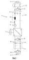
- the device 1 comprises an inverter 4 with an upstream intermediate circuit 5 and a downstream EMC filter 6.
- the DC voltage source 2 is connected to the inverter 4 via a switch 7 who in Fig. 1 closed is.
- the intermediate circuit 5 is here a voltage intermediate circuit with an intermediate circuit capacitor 8.
- the EMC filter has an EMC capacitor 9 and an EMC throttle 10.
- embodiments of the present invention can be based on any RLC combinations which may also be provided internally and deviated from, possibly cascaded, by an EMC filter.
- the EMC filter 6 is connected between the inverter 4 and a power switch 11 to provide the AC power network 3 periodic, for example, sinusoidal AC power when the power switch 11 is closed.
- the power switch 11 is designed as the switch 7, for example, as a relay or contactor. During the inventive determination of the load capacity of the DC voltage source 2, the power switch 11 is open, as in Fig. 1 is shown.
- the device 1 comprises a plurality of measuring devices.
- a voltmeter 12 measures the output voltage U Q of the DC voltage source 2.
- the intermediate circuit voltage U z across the DC link capacitor 8 is measured by a voltmeter 13.
- the voltage A AC at the output of the EMC filter 6 measures a voltmeter 14.
- an ammeter 15 of AC 16 measured on the AC side of the inverter 4.
- the inverter 4 is controlled by a controller 17, which determines in particular the frequency to which the inverter 4 is directed.
- control device 17 controls the individual switches of the inverter 4 according to the concept of pulse width modulation high frequency so that the alternating current 16 is even before the EMC filter 6 is approximately sinusoidal.
- the output voltage U Q increases as a DC voltage source 2 with the irradiation intensity after sunrise.
- the device 1 is put into operation and the switch 7 is closed.
- the inverter 4 starts to work at idle.
- the load capacity of the DC voltage source 2 by loading the same with a test load and simultaneously detecting a DC input voltage of the inverter in the form of the output voltage U Q of the DC voltage source 2 and / or the intermediate circuit voltage U z determined.
- the controller 17 controls the inverter 4 so that a four-quadrant operation is possible and that the AC 16 is not on the grid frequency of the AC network 3, but on a different from this Test frequency is directed.
- the EMC filter 6 connected on the output side and / or one or more comparable RLC component (s) of the inverter 4 are / are excited to forced oscillations.
- a voltage and / or current increase occurs at the EMC throttle 10 and the EMC capacitor 9 of the EMC filter 6.
- test frequency By suitable choice of the test frequency, to which the inverter 4 is directed, for example, an increased alternating current 16 between the inverter 4 and the EMC filter 6 at the same time not exceeding the component limits on the EMC capacitor 9 can be realized.
- Dependent z. B. from this increased AC 16 inter alia, switching losses of bridge semiconductors of the inverter 4.
- a mains connection by closing the power switch 11 is only useful if the test load can be provided immediately from the DC voltage source 2 under the currently given conditions, so that the observed input DC voltage U Q or U z does not break more than by a defined limit.
- the set test load is converted into heat in the inverter 4.
- the resulting heating of the inverter 4 is not critical in any meaningful implementation of the new method.
- a test frequency of the inverter is selectively set, which avoids, in accordance with the intended test load, a voltage or current exceeding the component limits on the RLC components used for the method.
- each inverter 4 in combination with a particular EMC filter 6 has an individual - for a given test load necessary - instantaneous test frequency.
- the test load itself, which must be provided instantaneously by the DC voltage source 2, in order to ensure a safe connection to the AC network 3, for example, with variations of the AC network 3 change.
- An advantageous embodiment of the new method therefore provides for the test frequency of the inverter 4, with which the load capacity of the DC voltage source 2 is determined, to be adapted individually to the current state and the current operating conditions of the respective inverter by an adaptive, fully automatic learning algorithm. This adaptive adjustment of the test frequency can be carried out step by step during regular connection tests.
- test frequencies which are higher than the mains frequency, typically start in the range of 110% of the mains frequency of the AC mains 3 and can therefrom range from 16 kHz to about 8 kHz at a frequency of the inverter. At a different clock frequency, the range of the test frequency is to be dimensioned accordingly.
- the specific test frequencies result from the fact that the new method uses the flanks of the amplitude resonance behavior of the EMC filter 6.
- the inventive method for determining the load capacity of the DC voltage source 2 can be started, for example, if the difference between a generated at power switch 11 from the inverter 4 AC voltage at mains frequency, at a timing of the inverter 4, which allows a four-quadrant operation, and at Open mains switch 11 measured mains peak voltage of the AC mains exceeds a threshold.
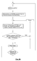
- the results in Fig. 2 reproduced schedule.
- the starting point is the successful completion of all system tests before reaching the network switching procedure, that is, the power switch 11 is open.
- all inverter mechanisms for the stabilization of the DC link 5 are deactivated.
- the DC voltage source 2 is first subjected to a low test load, for example by the activation of a clocking of the inverter 4, which allows a four-quadrant operation. In such a case, it is advantageous if the inverter 4 is directed to the mains frequency of the AC mains 3.
- the inverter 4 If the difference between the peak value of the output voltage of the inverter 4 and the peak value of the AC voltage of the AC network 3 does not exceed a defined threshold value, the inverter 4 is caused to pause, after the end of which it continues again with the activation of the initially small test load. If, however, the already mentioned threshold is exceeded, a timer is started. Should the intermediate circuit voltage U z have decreased too much due to the activated test load before expiration of this timer, which indicates an insufficient load capacity of the DC voltage source 2, the inverter 4 in turn goes into the pause state. This state is also assumed when the intermediate circuit voltage U z has dropped after the expiry of the timer.
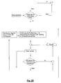
- the test load may be increased by appropriately changing the test frequency to which the inverter 4 is directed while maintaining four-quadrant operation against the line frequency.
- the timer is started, which detects the change in the intermediate circuit voltage U z in view of the now larger test load. If the intermediate circuit voltage U z breaks below the larger test load (irrespective of whether the timer has reached its end value), the test load is repeated after a pause has elapsed.
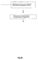
- the difference between the peak voltage of the inverter output voltage when directing the inverter to the mains frequency and the peak voltage of the AC voltage of the AC network 3 is formed again. If this difference does not exceed a defined threshold value, the last set test load must be retested after a pause. Conversely, the said threshold value is reached, a synchronization of the inverter output voltage can be made with that of the AC mains and a Netzzuschalt bath be undertaken.
Landscapes
- Engineering & Computer Science (AREA)
- Power Engineering (AREA)
- Inverter Devices (AREA)
Description
Die Erfindung bezieht sich auf ein Verfahren zur Ermittlung der Belastbarkeit einer über einen Wechselrichter und einen Netzschalter einem Wechselstromnetz mit einer vorgegebenen Netzfrequenz zuschaltbaren Gleichspannungsquelle, das die Merkmale des Oberbegriffs des unabhängigen Patentanspruchs 1 aufweist, sowie auf eine Vorrichtung zur Umsetzung dieses Verfahrens.The invention relates to a method for determining the load capacity of a switchable via an inverter and a power switch an AC network with a predetermined power frequency switchable DC voltage source having the features of the preamble of
Insbesondere ist die vorliegende Erfindung zur Anwendung bei der dezentralen Einspeisung in ein Wechselstromnetz vorgesehen, bei dem es sich um ein Energieversorgungsnetz, ein Inselnetz, aber auch um die Energieversorgung eines einzelnen Verbrauchers handeln kann. Dabei dient der Wechselrichter dazu, aus der von der Gleichspannungsquelle, zum Beispiel einer Photovoltaik-, Wind-, Wasserkraftanlage oder einem Gleichstromgenerator, generierten Gleichspannung eine netzkonforme Wechselspannung zu erzeugen und elektrische Leistung von der Gleichspannungsquelle in das Wechselstromnetz einzuspeisen.In particular, the present invention is intended for use in the decentralized supply to an AC network, which may be a power grid, an isolated grid, but also the power supply of a single consumer. In this case, the inverter is used to generate from the DC voltage source, such as a photovoltaic, wind, hydro or DC generator, DC voltage generated a grid-compatible AC voltage and feed electrical power from the DC voltage source in the AC grid.
Für die gewünschte Maximierung des Anteils an regenerativen Energien am Gesamtenergieverbrauch ist in jedem der genannten Fälle eine möglichst frühzeitige und dauerhafte Netzzuschaltung der Gleichspannungsquelle wünschenswert. Gleichzeitig ist einer möglichst großen Schonung aller Bauteile einer hierfür verwendeten Vorrichtung Rechnung zu tragen, um eine möglichst lange Betriebsdauer dieser Vorrichtung zu erreichen. Die Zuschaltung sollte daher, wenn die Gleichspannungsquelle eine hierfür ausreichende Belastbarkeit aufweist, sofort erfolgen, aber nicht schon früher.For the desired maximization of the proportion of regenerative energies in the total energy consumption, the earliest possible and permanent mains connection of the DC voltage source is desirable in each case mentioned. At the same time the greatest possible protection of all components of a device used for this purpose is to be taken in order to achieve the longest possible service life of this device. The connection should therefore take place immediately if the DC voltage source has sufficient load capacity, but not earlier.
Im einfachsten Fall wird die Belastbarkeit der Gleichspannungsquelle vor ihrer Netzzuschaltung über den Wechselrichter aus ihrer Leerlaufspannung abgeleitet. Diese ohne auf die Gleichspannungsquelle einwirkende Lasten vorliegende Leerlaufspannung spiegelt die augenblickliche Leistungsfähigkeit der Gleichspannungsquelle jedoch nicht ausreichend wider. So kann zum Beispiel ein Photovoltaikmodul, wenn beim morgendlichen Zuschalten widrige Wetterbedingungen herrschen, trotz Erreichens des für die Netzzuschaltung erforderlichen Spannungsschwellwerts nicht genügend Leistung bereitstellen, um den nachgeschalteten Wechselrichter nach Abzug von dessen Eigenbedarf, das ist der für den Betrieb des Wechselrichters erforderliche Bedarf, dauerhaft im Einspeisebetrieb am Wechselstromnetz zu halten. Dies hat zur Folge, dass der Wechselrichter kurz nach erfolgter Zuschaltung zum Netz wieder vom Netz getrennt werden muss. Die hieraus resultierenden zusätzlichen Schaltungsoperationen begrenzen die Lebensdauer, insbesondere diejenige des Netzschalters, erheblich.In the simplest case, the load capacity of the DC voltage source is derived from its open circuit voltage via the inverter before it is connected to the grid. However, this no load voltage applied to the DC voltage source does not sufficiently reflect the instantaneous performance of the DC voltage source. For example, a photovoltaic module, despite adverse weather conditions when connected in the morning, may not provide sufficient power to reach the downstream inverter after deducting its own demand, which is the need for inverter operation to be kept in the AC supply during feed-in operation. As a result, the inverter must be disconnected from the grid shortly after connection to the grid. The resulting additional circuit operations limit the life, especially that of the power switch, considerably.
Bei einem Verfahren mit den Merkmalen des Oberbegriffs des unabhängigen Patentanspruchs 1 wird eine Eingangsgleichspannung, die die Ausgangsspannung der Gleichspannungsquelle oder die Spannung eines Zwischenkreises des Wechselrichters sein kann, bei noch geöffnetem Netzschalter aber bereits angesteuertem Wechselrichter erfasst, so dass auf die Gleichspannungsquelle der Eigenbedarf des Wechselrichters als kleine Prüflast einwirkt. Die Ausgangsspannung der Gleichspannungsquelle ist damit nicht mehr ihre reine Leerlaufspannung. Der Eigenbedarf des Wechselrichters ist jedoch regelmäßig zu klein, um als Prüflast für die Netzzuschaltung der Gleichstromquelle auszureichen. Das heißt, die mit Hilfe des Eigenbedarfs ermittelte Belastbarkeit der Gleichspannungsquelle sagt immer noch zu wenig über deren Belastbarkeit bei ihrer Netzzuschaltung aus.In a method having the features of the preamble of
Um eine Gleichspannungsquelle vor ihrer Netzzuschaltung über einen Wechselrichter mit einer höheren Prüflast zu beaufschlagen, ist es aus der
Aus der
In Dokument
Der Erfindung liegt die Aufgabe zugrunde, ein Verfahren zur Ermittlung der Belastbarkeit einer Gleichspannungsquelle mit den Merkmalen des Oberbegriffs des unabhängigen Patentanspruchs 1 aufzuzeigen, das das Zuschalten der Gleichspannungsquelle über den Wechselrichter an das Wechselstromnetz zu einem optimalen Zeitpunkt ermöglicht, bei dem weder eine Gefahr der Notwendigkeit einer neuerlichen Netztrennung besteht, noch die Gleichspannungsquelle für unnötig lange Zeiträume dem Wechselstromnetz noch nicht zugeschaltet wird.The invention has for its object to provide a method for determining the load capacity of a DC voltage source having the features of the preamble of
Erfindungsgemäß wird diese Aufgabe durch ein Verfahren mit den Merkmalen des unabhängigen Patentanspruchs 1 gelöst. Die abhängigen Patentansprüche 2 bis 13 betreffen bevorzugte Ausführungsformen des neuen Verfahrens. Der nebengeordnete Patentanspruch 14 ist auf eine Vorrichtung mit einem Wechselrichter und einer Steuereinrichtung gerichtet, die den Wechselrichter nach dem neuen Verfahren ansteuert. Der Patentanspruch 15 betrifft eine bevorzugte Ausführungsform der neuen Vorrichtung.According to the invention, this object is achieved by a method having the features of
Bei dem neuen Verfahren zur Ermittlung der Belastbarkeit einer über einen Wechselrichter und einen Netzschalter einem Wechselstromnetz mit einer vorgegebenen Netzfrequenz zuschaltbaren Gleichspannungsquelle wird eine Eingangsgleichspannung des Wechselrichters, bei der es sich um die Ausgangsspannung der Gleichspannungsquelle oder eine Spannung in einem Zwischenkreis des Wechselrichters handeln kann, bei geöffnetem Netzschalter und bei einer einen Vier-Quadrantenbetrieb ermöglichenden Ansteuerung des Wechselrichters erfasst, wobei der Wechselrichter so angesteuert wird, dass er die Eingangsgleichspannung auf eine von der Netzfrequenz abweichende Prüffrequenz wechselrichtet. Abweichend bedeutet in diesem Zusammenhang, dass die Prüffrequenz sowohl niedriger als auch höher als die Netzfrequenz sein kann. Häufig wird sie bei der Erfindung höher als die Netzfrequenz sein. Bei geeigneter Wahl der Prüffrequenz in Hinblick auf den jeweiligen Wechselrichter und seine Einsatzumgebung kann auf diese Weise eine auf die Gleichspannungsquelle einwirkende Prüflast erheblich über den Eigenbedarf des Wechselrichters bei der Netzfrequenz erhöht werden. Konkret kann sie in aller Regel problemlos auf ein Niveau gebracht werden, das der Belastung der Gleichspannungsquelle bei ihrer Netzzuschaltung entspricht, so dass die Möglichkeit einer gefahrlosen Netzzuschaltung frühzeitig und sicher feststellbar ist.In the new method for determining the load capacity of a direct current voltage source which can be connected via an inverter and a power switch to an AC network having a predetermined line frequency, an input DC voltage of the inverter, which may be the output voltage of the DC voltage source or a voltage in a DC link of the inverter, is added in an open four-quadrant operation enabling control of the inverter detected, wherein the inverter is controlled so that it inverts the input DC voltage to a deviating from the mains frequency test frequency. Deviating means in this context that the test frequency can be both lower and higher than the mains frequency. Often it will be higher than the grid frequency in the invention. With a suitable choice of the test frequency with regard to the respective inverter and its environment of use can be increased in this way a force acting on the DC voltage test load considerably over the intrinsic demand of the inverter at the mains frequency. Specifically, it can usually be easily brought to a level that corresponds to the load of the DC voltage source at their power supply, so that the possibility of a safe mains connection is detected early and safely.
Wenn der Wechselrichter bei geöffnetem Netzschalter so angesteuert wird, dass er die Eingangsgleichspannung nacheinander auf verschiedene Prüffrequenzen wechselrichtet, von denen zumindest eine von der Netzfrequenz abweicht, kann insbesondere auch das Verhalten der Gleichspannungsquelle gegenüber Laständerungen ermittelt werden. Dieses Verhalten ist neben der absoluten Belastbarkeit ein wichtiges Kriterium für die gefahrlose Zuschaltbarkeit der Gleichspannungsquelle zu dem Wechselstromnetz.If the inverter is controlled with the power switch open in such a way that it alternately switches the input DC voltage to different test frequencies, of which at least one deviates from the mains frequency, the behavior of the DC voltage source relative to load changes can be determined in particular. This behavior is, in addition to the absolute load capacity, an important criterion for the safe connectability of the DC voltage source to the AC network.
Für das Verhalten gegenüber wechselnden Belastungen ist von besonderem Interesse, wie die Gleichspannungsquelle auf Laständerungen, insbesondere auf Lastsprünge aber auch auf stetige Laständerungen, reagiert. Um diese zu simulieren, kann der Wechselrichter bei geöffnetem Netzschalter so angesteuert werden, dass die auf die Gleichspannungsquelle einwirkende Prüflast entsprechend, d. h. insbesondere stufenförmig variiert wird.For the behavior against changing loads is of particular interest, as the DC voltage source to load changes, in particular to load jumps but also to steady load changes responded. To simulate this, the inverter can be controlled with open power switch so that the test load acting on the DC voltage source accordingly, d. H. is varied in particular stepwise.
Je nach konkretem Aufbau des Wechselrichters und seiner Einsatzumgebung kann es ausreichen, dass die Prüffrequenz von der Netzfrequenz um 10 % abweicht, um eine Prüflast hervorzurufen, die klare Aussagen über die Belastbarkeit der Gleichspannungsquelle erlaubt.Depending on the specific structure of the inverter and its environment of use, it may be sufficient for the test frequency to deviate from the mains frequency by 10% in order to produce a test load that allows clear statements about the load capacity of the DC voltage source.
Vorzugsweise weicht die Prüffrequenz von der Netzfrequenz jedoch um mindestens 20 % nach unten oder oben, mehr bevorzugt um mindestens 40 % nach unten oder oben, noch mehr bevorzugt um mindestens 60 % nach unten oder oben und am meisten bevorzugt um mindestens 100 % nach oben ab.Preferably, however, the test frequency deviates from the line frequency by at least 20% down or up, more preferably at least 40% down or up, even more preferably at least 60% down or up, and most preferably at least 100% upwards ,
Bei einer Netzfrequenz in einem typischen Bereich von 50-60 Hz kann eine nach oben abweichende Prüffrequenz eine typische Größenordnung von ungefähr 1 kHz aufweisen, d. h. von etwa 500 bis 8.000 Hz betragen, so dass sie beispielsweise bei einer üblichen Taktfrequenz der schnell getakteten Schalter des Wechselrichters von 16 kHz problemlos einstellbar ist. Bei einer hiervon abweichenden Taktfrequenz der schnell getakteten Schalter des Wechselrichters kann eine Prüffrequenz aus einem anderen Bereich günstiger sein. In der Regel sollte die Prüffrequenz nicht mehr als 50 % dieser Taktfrequenz betragen.At a line frequency in a typical range of 50-60 Hz, an upwardly-varying test frequency may have a typical magnitude of approximately 1 kHz, i. H. be from about 500 to 8000 Hz, so that it is easily adjustable, for example, at a common clock frequency of the clocked switch of the inverter of 16 kHz. In a deviating clock frequency of the fast-clocked switch of the inverter, a test frequency from another area may be cheaper. As a rule, the test frequency should not exceed 50% of this clock frequency.
Durch die Abweichung der Prüffrequenz von der Netzfrequenz können jedwede Wechselstromwiderstände und Schaltwiderstände im Bereich des Wechselrichters, eines Zwischenkreises oder nachgeschalteter Bauteile bis zu dem geöffneten Netzschalter ausgenutzt werden, um die Prüflast auf das gewünschte Niveau anzuheben. Besonders effektiv ist es jedoch, wenn die Prüffrequenz in die Nähe der Resonanzfrequenz eines zwischen den Wechselrichter und den Netzschalter geschalteten EMV-Filters oder einer vergleichbaren, ggf. kaskadierten geräteinternen RLC-Komponente des Wechselrichters abgestimmt wird, wobei die eigentliche Resonanzfrequenz inklusive eines definierten Toleranzbereiches mit der Prüffrequenz zu meiden ist. Ein derartiges EMV-Filter ist bei vielen Vorrichtungen vorhanden, auf deren Betrieb sich die vorliegende Erfindung bezieht. Wenn die Prüffrequenz in die Nähe der Resonanzfrequenz des EMV-Filters kommt, kann z. B. bei vergleichsweise kleiner Spannung zwischen den Ausgängen des EMV-Filters, die die Bauteilgrenzen nicht überschreitet, ein erhöhter, aber nicht unkontrollierter Wechselstrom durch den Wechselrichter erzeugt werden. Für diesen Wechselstrom kann der Wechselrichter im Vier-Quadrantenbetrieb als Lastwiderstand wirken und so die gewünschte Prüflast bereitstellen. Mit einer Überlastung oder auch nur einer die Lebensdauer des Wechselrichters signifikant reduzierenden Belastung ist dabei nicht zu rechnen, da der durch den Wechselrichter fließende Wechselstrom signifikant kleiner als der Strom ist, für den der Wechselrichter ausgelegt ist, um die maximale Leistung von der Gleichspannungsquelle in das Wechselstromnetz zu übertragen. Aus der Durchführung des oben beschriebenen Verfahrens resultiert keine den Bestand oder die Lebensdauer des Wechselrichters gefährdende Temperaturerhöhung.Due to the deviation of the test frequency from the mains frequency, any AC resistances and switching resistances in the area of the inverter, an intermediate circuit or downstream components up to the open power switch can be utilized to raise the test load to the desired level. However, it is particularly effective when the test frequency is tuned to the vicinity of the resonant frequency of a switched between the inverter and the power switch EMC filter or a comparable, possibly cascaded device internal RLC component of the inverter, the actual resonant frequency including a defined tolerance range with the test frequency is to be avoided. Such an EMC filter is present in many devices on the operation of which the present invention relates. If the test frequency comes close to the resonance frequency of the EMC filter, z. B. at comparatively low voltage between the outputs of the EMC filter, which does not exceed the component limits, an increased, but not uncontrolled AC are generated by the inverter. For this alternating current, the inverter can act as a load resistor in four-quadrant operation to provide the desired test load. An overload or even a load significantly reducing the life of the inverter is not to be expected since the alternating current flowing through the inverter is significantly smaller than the current for which the inverter is designed to supply the maximum power from the DC voltage source to the inverter AC power to transfer. From the implementation of the method described above results in any inventory or the life of the inverter endangering temperature increase.
Um die Prüflast, mit der die Gleichspannungsquelle durch die Abweichung der Prüffrequenz von der Netzfrequenz beaufschlagt wird, konkret zu erfassen, kann der Wechselstrom von dem und/oder eine Wechselspannung über das EMV-Filter gemessen werden. Eine absolute Bestimmung der Prüflast ist jedoch nur dann von Bedeutung, wenn die spätere Belastung der dem Wechselstromnetz zugeschalteten Gleichspannungsquelle absolut bekannt ist. In der Praxis kann es daher hinreichen, zu schauen, ob die Prüflast, die mit einer bestimmten Prüffrequenz hervorgerufen wurde, und die zu keinem übermäßigen Einbruch der Eingangsgleichspannung geführt hat, groß genug war, um die Gleichspannungsquelle vor dem Zuschalten zu dem Wechselstromnetz auf ausreichende Belastbarkeit zu prüfen. Wenn nicht, muss die Prüflast geeignet angepasst werden. Hierzu kann die Prüffrequenz in Abhängigkeit von einer bekannten Beziehung zwischen der Prüflast und der Prüffrequenz verändert werden. Der idealen Prüffrequenz kann man sich aber auch nach den Grundsätzen der Fuzzy-Logik annähern, ohne eine derartige Beziehung zu kennen oder gar ohne dass eine derartige feste Beziehung überhaupt existiert.In order to concretely detect the test load, which is applied to the DC voltage source by the deviation of the test frequency from the mains frequency, the AC current from and / or an AC voltage can be measured via the EMC filter. However, an absolute determination of the test load is only of importance if the later load of the DC power supply connected DC voltage source is absolutely known. In practice, therefore, it may be sufficient to look to see if the test load, which was caused at a certain test frequency, and which did not lead to excessive dip in the DC input voltage, was large enough to provide the DC source with sufficient load capacity before being connected to the AC mains to consider. If not, the test load must be adjusted appropriately. For this purpose, the test frequency can be changed depending on a known relationship between the test load and the test frequency. The ideal test frequency can also be approximated according to the principles of fuzzy logic, without knowing such a relationship or even without such a fixed relationship even exists.
Mit einem derartigen Lernalgorithmus kann die Prüffrequenz an den jeweiligen Wechselrichter mit der Toleranz seiner Bauteile und dessen Betriebsumgebung zu Betriebsbeginn und laufend während seines Betriebs angepasst werden, um beispielsweise auftretende Alterungsprozesse auszugleichen.With such a learning algorithm, the test frequency can be adapted to the respective inverter with the tolerance of its components and its operating environment at the beginning of operation and continuously during its operation, for example, to compensate for aging processes occurring.
Der Lernalgorithmus kann auf eine Datenbasis mit Vergleichsdaten zurückgreifen, um zum einen einen Aufsetzpunkt für die Prüffrequenz in der Nähe der zu erwartenden idealen Prüffrequenz zu wählen und um andererseits die Prüffrequenz von vornherein in der zielführenden Richtung zu ändern, ohne zur Bestimmung dieser zielführenden Richtung auf Versuche angewiesen zu sein. Auch die Größe der Änderung kann unter Rückgriff auf die Vergleichsdaten erfolgen.The learning algorithm can rely on a database of comparative data, in order to choose a touchdown point for the test frequency in the vicinity of the expected ideal test frequency and on the other hand to change the test frequency in the targeted direction from the outset, without determining this goal-oriented direction on experiments to be instructed. The size of the change can also be made using the comparative data.
Durchgeführt werden kann der Lernalgorithmus schrittweise beim regulären Zuschalten der Gleichspannungsquelle über den Wechselrichter zu dem Wechselstromnetz. Dabei gilt es, ein Optimum zwischen der Vermeidung erneuter Netztrennungen einerseits und dem doch möglichst frühzeitigen Zuschalten der Gleichspannungsquelle zu dem Wechselstromnetz andererseits zu finden.The learning algorithm can be implemented stepwise during the regular connection of the DC voltage source via the inverter to the AC network. It is important to find an optimum between the avoidance of renewed network separations on the one hand and the earliest possible connection of the DC voltage source to the AC network on the other hand.
Es versteht sich, dass die Gleichspannungsquelle bei der Durchführung des neuen Verfahrens nur dann durch Schließen des Netzschalters über den Wechselrichter dem Wechselstromnetz zugeschaltet wird, wenn eine als ausreichend angesehene Belastbarkeit ermittelt wurde. Diese Belastbarkeit zeigt sich als Einhaltung eines maximal gestatteten Einbruchs der Eingangsgleichspannung des Wechselrichters bei einer bestimmten Prüffrequenz. Wenn sich die so definierte Belastbarkeit für die anschließende Einspeisung von der Gleichspannungsquelle über den Wechselrichter in das Wechselstromnetz als unzureichend herausstellt, kann nicht nur, wie bereits ausgeführt, die Prüffrequenz geändert werden, sondern auch der zulässige maximale Abfall der Eingangsgleichspannung reduziert werden. Umgekehrt müssen die Anforderungen an die Belastbarkeit der Gleichspannungsquelle vor dem Zuschalten so klein wie möglich belassen werden, um die Gleichspannungsquelle möglichst früh mit dem Wechselstromnetz zu verbinden.It is understood that the DC voltage source is only connected to the AC network by closing the power switch via the inverter when performing the new method, if a considered sufficient load capacity was determined. This load capacity is shown as compliance with a maximum permissible break in the DC input voltage of the inverter at a certain test frequency. If the load capacity defined in this way for the subsequent supply from the DC voltage source via the inverter to the AC network proves to be inadequate, not only can the test frequency be changed, as already explained, but also the permissible maximum drop of the DC input voltage can be reduced. Conversely, the requirements for the load capacity of the DC voltage source before connection must be left as small as possible in order to connect the DC voltage source as early as possible to the AC power grid.
Eine Vorrichtung zur Durchführung des neuen Verfahrens weist eine Steuereinrichtung auf, die den Wechselrichter nach dem neuen Verfahren ansteuert. Vorzugsweise umfasst die Vorrichtung dabei ein EMV-Filter, das zwischen den Wechselrichter und den Netzschalter geschaltet ist.An apparatus for carrying out the new method has a control device which controls the inverter according to the new method. Preferably, the device comprises an EMC filter which is connected between the inverter and the power switch.
Vorteilhafte Weiterbildungen der Erfindung sind in den Patentansprüchen definiert.Advantageous developments of the invention are defined in the patent claims.
Die Erfindung wird im Folgenden anhand eines konkreten Ausführungsbeispiels unter Bezugnahme auf die beigefügten Zeichnungen näher erläutert und beschrieben.
- Fig. 1
- zeigt den Aufbau einer Vorrichtung zur Einspeisung von elektrischer Energie von einer Gleichspannungsquelle in ein Wechselstromnetz während der Durchführung des erfindungsgemäßen Verfahrens zur Bestimmung der Belastbarkeit der Gleichspannungsquelle; und
- Fig. 2
- skizziert ein Steuerprogramm zur Durchführung des erfindungsgemäßen Verfahrens.
- Fig. 1
- shows the construction of a device for feeding electrical energy from a DC voltage source in an AC network during the implementation of the method according to the invention for determining the load capacity of the DC voltage source; and
- Fig. 2
- outlines a control program for carrying out the method according to the invention.
Die in
Aufgrund von Bauteiltoleranzen und Alterungseffekten verfügt jeder Wechselrichter 4 in Kombination mit einem bestimmten EMV-Filter 6 über eine individuelle - für eine vorgegebene Prüflast notwendige - augenblickliche Prüffrequenz. Dabei kann sich auch die Prüflast selbst, die von der Gleichspannungsquelle 2 augenblicklich bereitgestellt werden muss, um ein sicheres Zuschalten zu dem Wechselstromnetz 3 zu gewährleisten, beispielsweise mit Variationen des Wechselstromnetzes 3 ändern. Eine vorteilhafte Ausführungsform des neuen Verfahrens sieht daher vor, die Prüffrequenz des Wechselrichters 4, mit der die Belastbarkeit der Gleichspannungsquelle 2 ermittelt wird, durch einen adaptiven, vollautomatischen Lernalgorithmus individuell an den aktuellen Zustand und die aktuellen Betriebsbedingungen des jeweiligen Wechselrichters anzupassen. Diese adaptive Einstellung der Prüffrequenz kann schrittweise bei regulären Zuschaltversuchen vorgenommen werden. Dabei ist es vorteilhaft, schnellstmöglich nach erfolgreicher Netzzuschaltung die von dem Wechselrichter 4 in das Wechselstromnetz 3 eingespeiste Leistung zu messen und die Prüfleistung durch Veränderung der Prüffrequenz für die nächste Ermittlung der Belastbarkeit der Gleichspannungsquelle 2 vor dem nächsten Schließen des Netzschalters 11 dahingehend zu optimieren, dass der Betrag der im Zuschaltmoment in das Wechselstromnetz eingespeisten Leistung schrittweise minimiert wird. Dadurch wird gewährleistet, dass die Gleichspannungsquelle 2 dem Wechselstromnetz 3 möglichst früh zugeschaltet wird. Eine Netzzuschaltung wird nach dem erfindungsgemäßen Ermitteln der Belastbarkeit der Gleichspannungsquelle 2 dann vorgenommen, wenn die Spannung Uz am Zwischenkreis des an die Gleichspannungsquelle 2 angeschlossenen Wechselrichters 4 und/oder die Ausgangsspannung UQ der Gleichspannungsquelle 2 trotz aktivierter Prüflast stabil bleibt. Dabei werden etwaige Maßnahmen, die die Eingangsgleichspannung des Wechselrichters im normalen Netzeinspeisebetrieb gegebenenfalls konstant halten, sinnvoller Weise deaktiviert. In Versuchen hat sich herausgestellt, dass geeignete gegenüber der Netzfrequenz erhöhte Prüffrequenzen typischerweise im Bereich von 110 % der Netzfrequenz des Wechselstromnetzes 3 beginnen und von dort bei einer Taktfrequenz des Wechselrichters von 16kHz bis etwa 8 kHz reichen können. Bei einer abweichenden Taktfrequenz ist der Bereich der Prüffrequenz entsprechend zu dimensionieren. Die konkreten Prüffrequenzen ergeben sich daraus, dass das neue Verfahren die Flanken des Amplitudenresonanzverhaltens des EMV-Filters 6 ausnutzt. Gestartet werden kann das erfindungsgemäße Verfahren zur Ermittlung der Belastbarkeit der Gleichspannungsquelle 2 beispielsweise dann, wenn die Differenz aus einer bei geöffnetem Netzschalter 11 vom Wechselrichter 4 erzeugten Wechselspannung mit Netzfrequenz, bei einer Taktung des Wechselrichters 4, die einen Vier-Quadrantenbetrieb ermöglicht, und der bei geöffnetem Netzschalter 11 gemessenen Netzscheitelspannung des Wechselstromnetzes einen Schwellwert übersteigt. Hierdurch wird eine automatische Anpassung der Aktivierung des erfindungsgemäßen Verfahrens an die augenblicklichen Gegebenheiten des Wechselstromnetzes 3 erreicht.Due to component tolerances and aging effects, each
Bei dem erfindungsgemäßen Verfahren ergibt sich beispielsweise der in
- 11
- Vorrichtungcontraption
- 22
- GleichspannungsquelleDC voltage source
- 33
- WechselstromnetzAC power
- 44
- Wechselrichterinverter
- 55
- ZwischenkreisDC
- 66
- EMV-FilterEMC filters
- 77
- Schalterswitch
- 88th
- ZwischenkreiskondensatorLink capacitor
- 99
- EMV-KondensatorEMC capacitor
- 1010
- EMV-DrosselEMC throttle
- 1111
- Netzschalterpower switch
- 1212
- Spannungsmesservoltmeter
- 1313
- Spannungsmesservoltmeter
- 1414
- Spannungsmesservoltmeter
- 1515
- Strommesserammeter
- 1616
- Wechselstromalternating current
- 1717
- Steuereinrichtungcontrol device
- UQ U Q
-
Ausgangsspannung der Gleichspannungsquelle 2Output voltage of the
DC voltage source 2 - Uz U z
- ZwischenkreisspannungIntermediate circuit voltage
- UAC U AC
-
Wechselspannung am Ausgang des EMV-Filters 6AC voltage at the output of the
EMC filter 6
Claims (15)
- Method of determining the rating of a DC voltage source connectable to an AC power grid having a predetermined grid frequency via an inverter and a power switch, wherein an input DC voltage is measured with open power switch and while controlling the inverter in a way allowing for a four-quadrant operation, characterised in that the inverter (4) with open power switch (11) is controlled in such a way that it inverts the input DC voltage (UQ, Uz) to a test frequency deviating from the grid frequency to increase a test load impacting on the DC voltage source (2) beyond the station supply of the inverter at the grid frequency.
- Method of clam 1, characterised in that the inverter (4) with open power switch (11) is controlled in such a way that it inverts the input DC voltage (UQ, Uz) successively to different test frequencies.
- Method of claim 2, characterised in that the inverter (4) with open power switch (11) is controlled in such a way that it varies the test load impacting on the DC voltage source stepwise.
- Method of any of the claims 1 to 3, characterised in that the test frequency deviates from the grid frequency downwardly or upwardly by at least 10 %, preferably downwardly or upwardly by at least 20 %, more preferably downwardly or upwardly by at least 40 %, even more preferably downwardly or upwardly by at least 60 %, and most preferably upwardly by at least 100 %.
- Method of claim 4, characterised in that the test frequency, at a grid frequency in the range of 50 to 60 Hz, is in a range from 500 Hz up to 50 % of a pulse frequency at which quickly pulsed switches of the inverter are pulsed.
- Method of any of the claims 1 to 5, characterised in that the test frequency is tuned to be close to a resonance frequency of an EMC filter (6) connected between the inverter (4) and the power switch (11) and/or of an RLC component of the inverter (4), wherein the resonance frequency itself is avoided.
- Method of claim 6, characterised in that an AC current (16) through the inverter (4) is generated by means of a frequency-dependent impedance of the EMC filter (6) and/or an RLC component of the inverter.
- Method of claim 7, characterised in that the inverter (4) is operated as a load resistance to the AC current (16).
- Method of any of the claims 7 and 8, characterised in that the AC current (16) and/or an AC voltage across the EMC filter (6) or the RLC component of the inverter is measured for measuring the test load.
- Method of any of the claims 1 to 9, characterised in that the test frequency is adjusted via a learning algorithm to the respective inverter (4) and its operation surroundings.
- Method of claim 10, characterised in that the learning algorithm is executed step by step during regularly connecting the DC voltage source (2) to the AC power grid (3) via the inverter (4).
- Method of claim 10, characterised in that the learning algorithm accesses a data base comprising comparison data.
- Method of any of the claims 1 to 12, characterised in that the DC voltage source (2) is only connected to the AC power grid (3) via the inverter (4) by closing the power switch (11), if a sufficient rating has been determined.
- Apparatus comprising an inverter (4) and a power switch (11) to connect a DC voltage source (2) to an AC power grid (3) having a predetermined grid frequency, comprising a measurement device (12, 13) to measure an input DC voltage (UQ, Uz) of the inverter (4) and comprising a control device (17) which controls the inverter according to the method of any of the claims 1 to 13.
- Apparatus according to claim 14, characterised in that an EMC filter (6) is connected between the inverter (4) and the power switch (11).
Priority Applications (3)
| Application Number | Priority Date | Filing Date | Title |
|---|---|---|---|
| DK08169831.8T DK2190110T3 (en) | 2008-11-25 | 2008-11-25 | Determination of the load capacity of a DC source that can be connected to a power supply via an inverter and a mains switch |
| EP08169831A EP2190110B1 (en) | 2008-11-25 | 2008-11-25 | Determining the rating of a direct voltage source being connectable via an inverter and a power switch to an electricity network |
| US12/622,578 US8362658B2 (en) | 2008-11-25 | 2009-11-20 | Determination of the load capability of a DC voltage source which is connectable to an electric power grid via an inverter and a grid disconnect switch |
Applications Claiming Priority (1)
| Application Number | Priority Date | Filing Date | Title |
|---|---|---|---|
| EP08169831A EP2190110B1 (en) | 2008-11-25 | 2008-11-25 | Determining the rating of a direct voltage source being connectable via an inverter and a power switch to an electricity network |
Publications (3)
| Publication Number | Publication Date |
|---|---|
| EP2190110A1 EP2190110A1 (en) | 2010-05-26 |
| EP2190110A8 EP2190110A8 (en) | 2010-11-03 |
| EP2190110B1 true EP2190110B1 (en) | 2012-10-10 |
Family
ID=40626690
Family Applications (1)
| Application Number | Title | Priority Date | Filing Date |
|---|---|---|---|
| EP08169831A Active EP2190110B1 (en) | 2008-11-25 | 2008-11-25 | Determining the rating of a direct voltage source being connectable via an inverter and a power switch to an electricity network |
Country Status (3)
| Country | Link |
|---|---|
| US (1) | US8362658B2 (en) |
| EP (1) | EP2190110B1 (en) |
| DK (1) | DK2190110T3 (en) |
Cited By (1)
| Publication number | Priority date | Publication date | Assignee | Title |
|---|---|---|---|---|
| WO2014140281A1 (en) | 2013-03-14 | 2014-09-18 | Sma Solar Technology Ag | Method for black start of a power station comprising a plurality of inverters connectable to an ac electrical grid |
Families Citing this family (12)
| Publication number | Priority date | Publication date | Assignee | Title |
|---|---|---|---|---|
| US8352091B2 (en) * | 2009-01-02 | 2013-01-08 | International Business Machines Corporation | Distributed grid-interactive photovoltaic-based power dispatching |
| KR101097265B1 (en) * | 2010-02-25 | 2011-12-22 | 삼성에스디아이 주식회사 | Energy storage system and controlling method of the same |
| US8606424B2 (en) * | 2011-04-05 | 2013-12-10 | King Fahd University Of Petroleum And Minerals | Particle swarm optimization system and method for microgrids |
| DE102012104005A1 (en) | 2012-05-07 | 2013-11-07 | Adensis Gmbh | Photovoltaic system and method for operating a photovoltaic system for feeding electrical power into a medium-voltage network |
| CN103514365B (en) * | 2013-08-12 | 2016-09-07 | 国家电网公司 | Electric power system transient state successive instability mode search and association exchange profile recognition method |
| JP6247189B2 (en) * | 2014-10-02 | 2017-12-13 | ファナック株式会社 | Motor controller having a function of discharging DC link residual energy |
| US10447040B2 (en) | 2014-10-15 | 2019-10-15 | Cummins Power Generation Ip, Inc. | Programmable inverter for controllable grid response |
| CN104362618B (en) * | 2014-10-21 | 2017-02-15 | 深圳大学 | Obtaining method of driving components of mean square voltage of nodes in alternating current power grid |
| GB2560195B (en) * | 2017-03-03 | 2020-01-08 | Ge Energy Power Conversion Technology Ltd | Electric circuits and power systems incorporating the same |
| US10672918B2 (en) * | 2017-07-19 | 2020-06-02 | Solantro Semiconductor Corp. | Photovoltaic panel rapid shutdown and recovery |
| DE102021119899B4 (en) * | 2021-07-30 | 2023-05-25 | Sma Solar Technology Ag | METHOD OF OPERATING AN INVERTER AND INVERTERS |
| CN117394415B (en) * | 2023-12-13 | 2024-03-08 | 福建泛蓝新能源科技有限公司 | Household energy storage system and control method thereof |
Family Cites Families (10)
| Publication number | Priority date | Publication date | Assignee | Title |
|---|---|---|---|---|
| DE4325436C2 (en) * | 1993-07-29 | 2000-06-29 | Inst Luft & Kaeltetechnik Ggmbh | Circuit arrangement for MPP control of photovoltaic solar systems and circuit arrangement for carrying out the method |
| DE4328511C2 (en) * | 1993-08-25 | 1995-06-22 | Zsw | Switch-on control method and control circuit for an inverter coupling a solar generator to the power grid |
| JP4076721B2 (en) * | 1997-11-24 | 2008-04-16 | エイチ. ウィルス、ロバート | Isolated power-proof method and apparatus for distributed generation |
| US6111767A (en) * | 1998-06-22 | 2000-08-29 | Heliotronics, Inc. | Inverter integrated instrumentation having a current-voltage curve tracer |
| JP2001275259A (en) * | 2000-03-29 | 2001-10-05 | Canon Inc | Linked system inverter and distributed power generation system |
| US6933714B2 (en) * | 2002-02-19 | 2005-08-23 | Institut Fuer Solare Energieversorgungs-Technik (Iset) Verein An Der Universitaet Gesamthochschule Kassel E.V. | Method and apparatus for measuring the impedance of an electrical energy supply system |
| US7269036B2 (en) * | 2003-05-12 | 2007-09-11 | Siemens Vdo Automotive Corporation | Method and apparatus for adjusting wakeup time in electrical power converter systems and transformer isolation |
| WO2007086413A1 (en) * | 2006-01-27 | 2007-08-02 | Sansha Electric Manufacturing Co., Ltd. | Photovoltaic generation inverter |
| EP2003759B1 (en) * | 2007-06-14 | 2020-03-04 | SMA Solar Technology AG | Method for detection of grid islanding |
| WO2009014522A1 (en) * | 2007-07-26 | 2009-01-29 | Utc Power Corporation | Power system having ac and dc power sources |
-
2008
- 2008-11-25 EP EP08169831A patent/EP2190110B1/en active Active
- 2008-11-25 DK DK08169831.8T patent/DK2190110T3/en active
-
2009
- 2009-11-20 US US12/622,578 patent/US8362658B2/en active Active
Cited By (1)
| Publication number | Priority date | Publication date | Assignee | Title |
|---|---|---|---|---|
| WO2014140281A1 (en) | 2013-03-14 | 2014-09-18 | Sma Solar Technology Ag | Method for black start of a power station comprising a plurality of inverters connectable to an ac electrical grid |
Also Published As
| Publication number | Publication date |
|---|---|
| US20100127576A1 (en) | 2010-05-27 |
| US8362658B2 (en) | 2013-01-29 |
| EP2190110A8 (en) | 2010-11-03 |
| DK2190110T3 (en) | 2013-01-28 |
| EP2190110A1 (en) | 2010-05-26 |
Similar Documents
| Publication | Publication Date | Title |
|---|---|---|
| EP2190110B1 (en) | Determining the rating of a direct voltage source being connectable via an inverter and a power switch to an electricity network | |
| AT501424B1 (en) | METHOD FOR AN INVERTER AND INVERTER, ESPECIALLY SOLAR CHANGEARK | |
| EP2242160B1 (en) | Method and device for connecting a photovoltaic assembly to an alternating current network | |
| DE102011076553A1 (en) | CONTROL OF THE DC FLOW OF A PHOTOVOLTAIC SYSTEM | |
| DE102016102417B4 (en) | Protection circuit for a photovoltaic (PV) module, method for operating the protection circuit and photovoltaic (PV) system with such a protection circuit | |
| EP2745375B1 (en) | Time-delayed battery activation for an emergency request | |
| EP1818990A2 (en) | Solar module for a photovoltaic plant | |
| EP2299572A1 (en) | Starting a DC/DC converter with high-frequency transformer | |
| DE102007012590B3 (en) | solar module | |
| WO2020108959A1 (en) | Method for supplying electricity to the controller of an inverter, facility component, inverter and energy generation facility having such a facility component | |
| DE102012104315A1 (en) | A method of sequentially disconnecting / connecting electrical power sources from / to a common load | |
| EP3516701A1 (en) | Solar module, phovoltaic system, and voltage limitation method | |
| EP3560099B1 (en) | Circuit for voltage limitation in a photovoltaic field, photovoltaic field and method for voltage limitation | |
| EP2607011A1 (en) | Method of and device for electrical resistance welding by means of capacitor discharge | |
| DE102013109797A1 (en) | ionizer | |
| WO2015144390A1 (en) | Method and device for detecting and signalling a contact fault within a photovoltaic module | |
| EP2385608B1 (en) | Electromotor for furniture with an energy supply device | |
| EP3327911B1 (en) | Method for controlling a switch module based on thyristor switching elements | |
| WO2014037297A1 (en) | Method for increasing the service life of the intermediate circuit capacitor of an electric system which has an inverter, electric system, and control unit for an electric system | |
| EP3297115A1 (en) | Assembly with an energy storage device and energy converter for absorbing electrical energy from a power network and discharge of electrical energy to the power network | |
| WO2020148313A1 (en) | Wind turbine for feeding electrical power into an electrical supply network | |
| DE102016202169A1 (en) | Operating an arrangement of generator-operated electrical machine and active bridge rectifier | |
| WO2005081384A2 (en) | Apparatus and method for regulating a clock frequency of a power converter | |
| EP2192667A2 (en) | Energy feed device | |
| DE102015202912B3 (en) | Method and device for driving an active bridge rectifier when canceling a phase short circuit |
Legal Events
| Date | Code | Title | Description |
|---|---|---|---|
| PUAI | Public reference made under article 153(3) epc to a published international application that has entered the european phase |
Free format text: ORIGINAL CODE: 0009012 |
|
| 17P | Request for examination filed |
Effective date: 20090901 |
|
| AK | Designated contracting states |
Kind code of ref document: A1 Designated state(s): AT BE BG CH CY CZ DE DK EE ES FI FR GB GR HR HU IE IS IT LI LT LU LV MC MT NL NO PL PT RO SE SI SK TR |
|
| AX | Request for extension of the european patent |
Extension state: AL BA MK RS |
|
| RIN1 | Information on inventor provided before grant (corrected) |
Inventor name: WILFRIED GROOTE, DIPL.- ING. Inventor name: AHLBORN ALEXANDER, DR. RER. NAT. Inventor name: REICHENBAECHER WOLFGANG, DIPL.-ING |
|
| AKX | Designation fees paid |
Designated state(s): AT BE BG CH CY CZ DE DK EE ES FI FR GB GR HR HU IE IS IT LI LT LU LV MC MT NL NO PL PT RO SE SI SK TR |
|
| GRAP | Despatch of communication of intention to grant a patent |
Free format text: ORIGINAL CODE: EPIDOSNIGR1 |
|
| RIN1 | Information on inventor provided before grant (corrected) |
Inventor name: REICHENBAECHER, WOLFGANG, DIPL.-ING Inventor name: AHLBORN, ALEXANDER, DR. RER. NAT. Inventor name: GROOTE, WILFRIED, DIPL.- ING. |
|
| GRAS | Grant fee paid |
Free format text: ORIGINAL CODE: EPIDOSNIGR3 |
|
| GRAA | (expected) grant |
Free format text: ORIGINAL CODE: 0009210 |
|
| AK | Designated contracting states |
Kind code of ref document: B1 Designated state(s): AT BE BG CH CY CZ DE DK EE ES FI FR GB GR HR HU IE IS IT LI LT LU LV MC MT NL NO PL PT RO SE SI SK TR |
|
| REG | Reference to a national code |
Ref country code: GB Ref legal event code: FG4D Free format text: NOT ENGLISH |
|
| REG | Reference to a national code |
Ref country code: AT Ref legal event code: REF Ref document number: 579344 Country of ref document: AT Kind code of ref document: T Effective date: 20121015 Ref country code: CH Ref legal event code: EP |
|
| REG | Reference to a national code |
Ref country code: IE Ref legal event code: FG4D Free format text: LANGUAGE OF EP DOCUMENT: GERMAN |
|
| REG | Reference to a national code |
Ref country code: DE Ref legal event code: R096 Ref document number: 502008008361 Country of ref document: DE Effective date: 20121213 |
|
| REG | Reference to a national code |
Ref country code: DK Ref legal event code: T3 |
|
| PG25 | Lapsed in a contracting state [announced via postgrant information from national office to epo] |
Ref country code: SI Free format text: LAPSE BECAUSE OF FAILURE TO SUBMIT A TRANSLATION OF THE DESCRIPTION OR TO PAY THE FEE WITHIN THE PRESCRIBED TIME-LIMIT Effective date: 20121010 |
|
| REG | Reference to a national code |
Ref country code: NL Ref legal event code: VDEP Effective date: 20121010 |
|
| REG | Reference to a national code |
Ref country code: LT Ref legal event code: MG4D |
|
| PG25 | Lapsed in a contracting state [announced via postgrant information from national office to epo] |
Ref country code: ES Free format text: LAPSE BECAUSE OF FAILURE TO SUBMIT A TRANSLATION OF THE DESCRIPTION OR TO PAY THE FEE WITHIN THE PRESCRIBED TIME-LIMIT Effective date: 20130121 Ref country code: NO Free format text: LAPSE BECAUSE OF FAILURE TO SUBMIT A TRANSLATION OF THE DESCRIPTION OR TO PAY THE FEE WITHIN THE PRESCRIBED TIME-LIMIT Effective date: 20130110 Ref country code: LT Free format text: LAPSE BECAUSE OF FAILURE TO SUBMIT A TRANSLATION OF THE DESCRIPTION OR TO PAY THE FEE WITHIN THE PRESCRIBED TIME-LIMIT Effective date: 20121010 Ref country code: NL Free format text: LAPSE BECAUSE OF FAILURE TO SUBMIT A TRANSLATION OF THE DESCRIPTION OR TO PAY THE FEE WITHIN THE PRESCRIBED TIME-LIMIT Effective date: 20121010 Ref country code: HR Free format text: LAPSE BECAUSE OF FAILURE TO SUBMIT A TRANSLATION OF THE DESCRIPTION OR TO PAY THE FEE WITHIN THE PRESCRIBED TIME-LIMIT Effective date: 20121010 Ref country code: IS Free format text: LAPSE BECAUSE OF FAILURE TO SUBMIT A TRANSLATION OF THE DESCRIPTION OR TO PAY THE FEE WITHIN THE PRESCRIBED TIME-LIMIT Effective date: 20130210 Ref country code: SE Free format text: LAPSE BECAUSE OF FAILURE TO SUBMIT A TRANSLATION OF THE DESCRIPTION OR TO PAY THE FEE WITHIN THE PRESCRIBED TIME-LIMIT Effective date: 20121010 Ref country code: FI Free format text: LAPSE BECAUSE OF FAILURE TO SUBMIT A TRANSLATION OF THE DESCRIPTION OR TO PAY THE FEE WITHIN THE PRESCRIBED TIME-LIMIT Effective date: 20121010 |
|
| BERE | Be: lapsed |
Owner name: SMA SOLAR TECHNOLOGY A.G. Effective date: 20121130 |
|
| PG25 | Lapsed in a contracting state [announced via postgrant information from national office to epo] |
Ref country code: GR Free format text: LAPSE BECAUSE OF FAILURE TO SUBMIT A TRANSLATION OF THE DESCRIPTION OR TO PAY THE FEE WITHIN THE PRESCRIBED TIME-LIMIT Effective date: 20130111 Ref country code: LV Free format text: LAPSE BECAUSE OF FAILURE TO SUBMIT A TRANSLATION OF THE DESCRIPTION OR TO PAY THE FEE WITHIN THE PRESCRIBED TIME-LIMIT Effective date: 20121010 Ref country code: PT Free format text: LAPSE BECAUSE OF FAILURE TO SUBMIT A TRANSLATION OF THE DESCRIPTION OR TO PAY THE FEE WITHIN THE PRESCRIBED TIME-LIMIT Effective date: 20130211 Ref country code: PL Free format text: LAPSE BECAUSE OF FAILURE TO SUBMIT A TRANSLATION OF THE DESCRIPTION OR TO PAY THE FEE WITHIN THE PRESCRIBED TIME-LIMIT Effective date: 20121010 |
|
| REG | Reference to a national code |
Ref country code: CH Ref legal event code: PL |
|
| PG25 | Lapsed in a contracting state [announced via postgrant information from national office to epo] |
Ref country code: SK Free format text: LAPSE BECAUSE OF FAILURE TO SUBMIT A TRANSLATION OF THE DESCRIPTION OR TO PAY THE FEE WITHIN THE PRESCRIBED TIME-LIMIT Effective date: 20121010 Ref country code: EE Free format text: LAPSE BECAUSE OF FAILURE TO SUBMIT A TRANSLATION OF THE DESCRIPTION OR TO PAY THE FEE WITHIN THE PRESCRIBED TIME-LIMIT Effective date: 20121010 Ref country code: CH Free format text: LAPSE BECAUSE OF NON-PAYMENT OF DUE FEES Effective date: 20121130 Ref country code: LI Free format text: LAPSE BECAUSE OF NON-PAYMENT OF DUE FEES Effective date: 20121130 Ref country code: BG Free format text: LAPSE BECAUSE OF FAILURE TO SUBMIT A TRANSLATION OF THE DESCRIPTION OR TO PAY THE FEE WITHIN THE PRESCRIBED TIME-LIMIT Effective date: 20130110 Ref country code: CZ Free format text: LAPSE BECAUSE OF FAILURE TO SUBMIT A TRANSLATION OF THE DESCRIPTION OR TO PAY THE FEE WITHIN THE PRESCRIBED TIME-LIMIT Effective date: 20121010 |
|
| PLBE | No opposition filed within time limit |
Free format text: ORIGINAL CODE: 0009261 |
|
| STAA | Information on the status of an ep patent application or granted ep patent |
Free format text: STATUS: NO OPPOSITION FILED WITHIN TIME LIMIT |
|
| REG | Reference to a national code |
Ref country code: IE Ref legal event code: MM4A |
|
| PG25 | Lapsed in a contracting state [announced via postgrant information from national office to epo] |
Ref country code: BE Free format text: LAPSE BECAUSE OF NON-PAYMENT OF DUE FEES Effective date: 20121130 Ref country code: RO Free format text: LAPSE BECAUSE OF FAILURE TO SUBMIT A TRANSLATION OF THE DESCRIPTION OR TO PAY THE FEE WITHIN THE PRESCRIBED TIME-LIMIT Effective date: 20121010 |
|
| 26N | No opposition filed |
Effective date: 20130711 |
|
| GBPC | Gb: european patent ceased through non-payment of renewal fee |
Effective date: 20130110 |
|
| PG25 | Lapsed in a contracting state [announced via postgrant information from national office to epo] |
Ref country code: IE Free format text: LAPSE BECAUSE OF NON-PAYMENT OF DUE FEES Effective date: 20121125 |
|
| REG | Reference to a national code |
Ref country code: DE Ref legal event code: R097 Ref document number: 502008008361 Country of ref document: DE Effective date: 20130711 |
|
| PG25 | Lapsed in a contracting state [announced via postgrant information from national office to epo] |
Ref country code: CY Free format text: LAPSE BECAUSE OF FAILURE TO SUBMIT A TRANSLATION OF THE DESCRIPTION OR TO PAY THE FEE WITHIN THE PRESCRIBED TIME-LIMIT Effective date: 20121010 Ref country code: GB Free format text: LAPSE BECAUSE OF NON-PAYMENT OF DUE FEES Effective date: 20130110 Ref country code: MT Free format text: LAPSE BECAUSE OF FAILURE TO SUBMIT A TRANSLATION OF THE DESCRIPTION OR TO PAY THE FEE WITHIN THE PRESCRIBED TIME-LIMIT Effective date: 20121010 |
|
| PG25 | Lapsed in a contracting state [announced via postgrant information from national office to epo] |
Ref country code: MC Free format text: LAPSE BECAUSE OF NON-PAYMENT OF DUE FEES Effective date: 20121130 Ref country code: TR Free format text: LAPSE BECAUSE OF FAILURE TO SUBMIT A TRANSLATION OF THE DESCRIPTION OR TO PAY THE FEE WITHIN THE PRESCRIBED TIME-LIMIT Effective date: 20121010 |
|
| PG25 | Lapsed in a contracting state [announced via postgrant information from national office to epo] |
Ref country code: LU Free format text: LAPSE BECAUSE OF NON-PAYMENT OF DUE FEES Effective date: 20121125 |
|
| PG25 | Lapsed in a contracting state [announced via postgrant information from national office to epo] |
Ref country code: HU Free format text: LAPSE BECAUSE OF FAILURE TO SUBMIT A TRANSLATION OF THE DESCRIPTION OR TO PAY THE FEE WITHIN THE PRESCRIBED TIME-LIMIT Effective date: 20081125 |
|
| REG | Reference to a national code |
Ref country code: FR Ref legal event code: PLFP Year of fee payment: 8 |
|
| PGFP | Annual fee paid to national office [announced via postgrant information from national office to epo] |
Ref country code: DK Payment date: 20151124 Year of fee payment: 8 |
|
| PGFP | Annual fee paid to national office [announced via postgrant information from national office to epo] |
Ref country code: AT Payment date: 20151120 Year of fee payment: 8 |
|
| REG | Reference to a national code |
Ref country code: FR Ref legal event code: PLFP Year of fee payment: 9 |
|
| REG | Reference to a national code |
Ref country code: DK Ref legal event code: EBP Effective date: 20161130 |
|
| REG | Reference to a national code |
Ref country code: AT Ref legal event code: MM01 Ref document number: 579344 Country of ref document: AT Kind code of ref document: T Effective date: 20161125 |
|
| PG25 | Lapsed in a contracting state [announced via postgrant information from national office to epo] |
Ref country code: AT Free format text: LAPSE BECAUSE OF NON-PAYMENT OF DUE FEES Effective date: 20161125 |
|
| REG | Reference to a national code |
Ref country code: FR Ref legal event code: PLFP Year of fee payment: 10 |
|
| PG25 | Lapsed in a contracting state [announced via postgrant information from national office to epo] |
Ref country code: DK Free format text: LAPSE BECAUSE OF NON-PAYMENT OF DUE FEES Effective date: 20161130 |
|
| PGFP | Annual fee paid to national office [announced via postgrant information from national office to epo] |
Ref country code: IT Payment date: 20231130 Year of fee payment: 16 Ref country code: FR Payment date: 20231123 Year of fee payment: 16 Ref country code: DE Payment date: 20231120 Year of fee payment: 16 |