EP2190097B1 - Method for operating an energy storage system - Google Patents
Method for operating an energy storage system Download PDFInfo
- Publication number
- EP2190097B1 EP2190097B1 EP08169829A EP08169829A EP2190097B1 EP 2190097 B1 EP2190097 B1 EP 2190097B1 EP 08169829 A EP08169829 A EP 08169829A EP 08169829 A EP08169829 A EP 08169829A EP 2190097 B1 EP2190097 B1 EP 2190097B1
- Authority
- EP
- European Patent Office
- Prior art keywords
- energy storage
- storage system
- charging
- physical
- power system
- Prior art date
- Legal status (The legal status is an assumption and is not a legal conclusion. Google has not performed a legal analysis and makes no representation as to the accuracy of the status listed.)
- Active
Links
Images


Classifications
-
- H—ELECTRICITY
- H02—GENERATION; CONVERSION OR DISTRIBUTION OF ELECTRIC POWER
- H02J—ELECTRIC POWER NETWORKS; CIRCUIT ARRANGEMENTS OR SYSTEMS FOR SUPPLYING OR DISTRIBUTING ELECTRIC POWER; SYSTEMS FOR STORING ELECTRIC ENERGY
- H02J3/00—Circuit arrangements for AC mains or AC distribution networks
- H02J3/28—Arrangements for balancing of the load in networks by storage of energy
- H02J3/32—Arrangements for balancing of the load in networks by storage of energy using batteries or super capacitors with converting means
-
- H—ELECTRICITY
- H02—GENERATION; CONVERSION OR DISTRIBUTION OF ELECTRIC POWER
- H02J—ELECTRIC POWER NETWORKS; CIRCUIT ARRANGEMENTS OR SYSTEMS FOR SUPPLYING OR DISTRIBUTING ELECTRIC POWER; SYSTEMS FOR STORING ELECTRIC ENERGY
- H02J7/00—Circuit arrangements for charging or discharging batteries or for supplying loads from batteries
- H02J7/80—Circuit arrangements for charging or discharging batteries or for supplying loads from batteries including monitoring or indicating arrangements
- H02J7/82—Control of state of charge [SOC]
-
- Y—GENERAL TAGGING OF NEW TECHNOLOGICAL DEVELOPMENTS; GENERAL TAGGING OF CROSS-SECTIONAL TECHNOLOGIES SPANNING OVER SEVERAL SECTIONS OF THE IPC; TECHNICAL SUBJECTS COVERED BY FORMER USPC CROSS-REFERENCE ART COLLECTIONS [XRACs] AND DIGESTS
- Y02—TECHNOLOGIES OR APPLICATIONS FOR MITIGATION OR ADAPTATION AGAINST CLIMATE CHANGE
- Y02E—REDUCTION OF GREENHOUSE GAS [GHG] EMISSIONS, RELATED TO ENERGY GENERATION, TRANSMISSION OR DISTRIBUTION
- Y02E70/00—Other energy conversion or management systems reducing GHG emissions
- Y02E70/30—Systems combining energy storage with energy generation of non-fossil origin
Definitions
- the present invention relates generally to the configuration and operation of an electric power system.
- the invention refers to a method for operating an energy storage system (ESS).
- ESS energy storage system
- An electric power system is unique in that aggregate production and consumption must be matched instantaneously and continuously, whilst all system elements should operate within acceptable limits. Unexpected loss of generating units or transmission lines, or errors in daily load forecast, result in sudden imbalances between generation and consumption. Such imbalances lead to frequency deviations from the nominal frequency of the power system. This is problematic because generators may get disconnected by over- or under-frequency protection systems and cause even larger deviations leading to a system blackout. Loads such as rotating machines, need to operate at constant frequency and therefore frequency deviations would result in the interruption of various manufacturing processes.
- a further problem known in electric power systems lies in the operational variations of renewable energy generation. These operational variations cause system frequency variation and transmission system operators must allocate more frequency regulation reserves than in the case of dispatchable energy generation.
- An ESS can be an effective means of alleviating these known problems.
- the ESS can function as a supplier of a frequency balancing reserve.
- An ESS may absorb power from the grid when the actual frequency is above a defined frequency tolerance band thereby charging the battery, and an ESS may provide power to the grid when the actual frequency is below the frequency tolerance band, in that case discharging the battery.
- WO 2007/104167 describes a method of operation of an ESS in which a lower state-of-charge set-point (SoC1) and an upper state-of-charge set-point (SoC2) of the battery are determined. These set-points lie between the minimum state-of-charge (SoCmin), wherein the battery is empty, and the maximum state-of-charge (SoCmax), wherein the battery is fully charged, respectively.
- SoCmin minimum state-of-charge
- SoCmax maximum state-of-charge
- WO 2008 058 284 discloses a method of operation of a BESS connected to the grid. Charge and discharge of the BESS is controlled based on measured SoC and load requirements.
- US Patent Number 5798633 discloses a battery energy storage system of the type in which an inverter is coupled to convert direct current power from a DC source to a control frequency AC power suitable for supplementing utility power or for replacing utility power.
- the battery energy storage system includes a control mechanism for operating the system and either a supplemental or replacement mode in parallel with a utility power system.
- WO 2005/029667 describes a system for regulating the frequency of generated power.
- An energy storage sub-system uses one or more flywheel energy storage systems to control the system frequency.
- an open-loop control uses a difference between measured frequency and reference frequency as an input signal.
- a disadvantage associated with such known ESSs is that the ESSs do not operate with optimum efficiency and have unnecessarily oversized dimensions. Therefore, there is a need for an efficient ESS having a charging rate which optimises operation.
- a method for operating an ESS for connection to a power system said energy storage system comprising a physical energy storage having a dynamically adjustable charging/discharging rate, the method comprising the steps of measuring a state of charge of the physical energy storage, obtaining a time-dependent forecast vector of properties of the energy storage system and the power system, determining a charging/discharging rate for the energy storage system, based on the measured state of charge and the time-dependent forecast vector, to maximise operational efficiency, and adjusting the charging/discharging rate of the physical energy storage in accordance with the determined charging/discharging rate.
- the step of determining a charging/discharging rate for the energy storage system further comprises determining a charging/discharging rate sequence.
- the step of measuring a state of charge of the physical energy storage further comprises determining a charge operation mode.
- the time-dependent forecast vector of properties of the energy storage system and the power system is based on historical data defining the properties of the energy storage system and the power system.
- an ESS that is operational for the purpose of frequency regulation, peak load shaving, arbitrage, load levelling or integration-of-renewables or other utility scale applications, is generally operated with a certain periodicity due to the nature of these purposes.
- a statistical analysis of the power system variables is performed over a time-span of at least one year to catch seasonal variations.
- Variables that may be analysed are nominal frequency, line load and customer peak load, renewable generation output, electricity market price variations. This analysis provides information on the time-dependent behaviour of these variables (ie. deviations from the nominal values) and is used to calculate a forecast vector, F.
- the step of determining a charging/discharging rate for the energy storage system to maximise operational efficiency is also based on a physical energy storage system model.
- the physical energy storage system model is modified dependent upon feedback of the state of charge of the physical energy storage.
- an ESS comprising a physical energy storage which is connectable to a power system, and a control unit for controlling the charging/discharging rate of the physical energy storage in accordance with the method of the first aspect.
- control unit stores the historical data defining the properties of the energy storage system and the power system, and has a state of charge input from the physical energy storage and a feedback input from the power system.
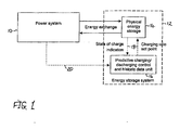
- a power system including an ESS is illustrated in Figure 1 .
- the power system 10 is in connection with the ESS 12 such that power can be transferred between them.
- the ESS 12 comprises a physical energy storage 14 and a control unit 16 which are in bidirectional communication 18 with each other.
- a further communication link 20 is located between the power system and the control system.
- the communication link 20 between the power system 10 and the control unit 16 functions to provide information on the power system 10 condition to the control unit 16.
- the control unit 16 comprises a predictive charging/discharging control function and a historic data unit.
- the control unit 16 provides charging rate set point to the ESS 12 and the ESS provides a state-of-charge indication to the control unit.
- the charging rate set point enables the ESS state of operation to be maintained within a certain optimal operating range.
- the further communication link 20 functions to provide feedback information to the control unit.
- the ESS of the present invention may be a battery, a flywheel, a super-capacitor, an ultra-capacitor or other type of energy storage system.
- the flow diagram of Figure 2 shows the steps in the control operation of the present invention.
- a computation of the charging rate sequence is initiated. This may occur periodically with period T (for example, 15 minutes for a load levelling application or 1-5 seconds for frequency control) or be triggered by an event such as a fault, a variation in the electricity price, or a variation in electricity demand.
- a state-of-charge at time k, L(k) is measured and in a third step, a time-dependent forecast vector F(k) is obtained.
- the time-dependent forecast vector F(k) is obtained by reading historical data, or it is generated by an external application, or it is generated by a black-box model running as an on line estimator and predictor.
- a charging rate sequence starting at time k, C (k), is determined for the operation of the ESS to maximize an objective function G tot (k), describing efficient operation and lifecycle aspects.
- the charging rate sequence C (k) determines the charging/discharging rate of the ESS.
- An optimal charging rate sequence C (k) over a horizon of M time steps is determined (as detailed with reference to Figure 3 ).
- the first value of the charging rate sequence C (k), C(k) is executed as a charge set point to the ESS.
- the procedure of finding a new optimal charging/discharging rate is repeated, and thus the next procedural step returns to the first step of Figure 2 and repeats the steps in the control operation in respect of times k+1,...,k+M.
- the state O(k+1) is defined as the new current charge operation mode.
- a Model-Predictive Control (MPC) standard may be utilized for the control operation computation defined in Figure 2 .
- the MPC enables an optimal control step to be determined that anticipates the behavior of the power system M time steps into the future. After the first cycle, the situation is reassessed by repeating the procedure. This allows the ESS to react on any unforeseen disturbances.
- FIG. 3 schematically shows the model on which the control logic is based for deducing the optimal control sequence.
- a model of a physical ESS receives an input from a physical parameter vector Q which comprises ESS and power system model parameters, from a one step time delay D and from a charging rate sequence at time k, C(k).
- the model of a physical ESS provides an output of L(k), O(k); where L(k) is the state of charge at time k, and O(k) is current charge operation mode.
- This output of the model of a physical ESS is input to an objective criterium block and also into the one step time delay D.
- the objective criterium block also receives inputs from an economic model parameter vector P, a time-dependent forecast vector F(k) and the charging rate sequence C (k).
- the objective criterium block provides an output of an objective function, G(k).
- G(k) the following parameters are stored in the historic data unit; the physical parameter vector Q, the economic model parameter vector P and the time-dependent forecast vector F(k).
- the charging rate sequence C (k) determines the charging/discharging rate of the ESS.
- the physical ESS model is a dynamic model which is comprised of two states - a level L(k) and a mode O(k).
- the level L(k) describes the amount of stored energy (also referred to as the "state of charge”).
- the mode O(k) is a discrete value;
- the physical parameter vector Q defines parameters such as the charge/discharge efficiency of the ESS and the storage efficiency of the ESS.
- the effect of the time delay D on states L(k) and O(k) is to modify them to L(k -1) and O(k -1), respectively.
- the level of the stored energy L(k) is determined as a function of the charge rate sequence C (k), the former level of stored energy L(k-1), the former mode O(k-1) (charging or discharging) and the physical parameter vector Q which comprises some physical parameters of the ESS and the power system.
- the objective criterium block functions to evaluate the objective function G(k) of the physical ESS model over a prediction horizon M for a charging rate sequence C (k).
- the prediction horizon M is a time period, the length of which is defined such that within this period the physical energy storage could be charged and discharged several times. (In practice, this can be from a few minutes up to a few hours, depending on the application.)
- the objective criterium block receives inputs from an economic model parameter vector P (comprising static economic model parameters) and a time-dependent forecast vector F (k) (comprising time-varying forecast variables).
- the static economic model parameters are, for example, ESS lifecycle cost (changing from charge to discharge, depth of discharge).
- the time-varying forecast variables are, for example, a forecast of power price, a forecast of power system frequency, a forecast of peak load and a forecast of charging/discharging capacity reserves.
- G k h ⁇ L k , F ⁇ k , C k , O k , O ⁇ k - 1 ; P ⁇
- the time-dependent forecast vector F(k) is obtained by reading-historical data, or it is generated by an external application, or it is generated by a black-box model running as an on-line estimator and predictor.
- control logic represented schematically in Figure 3 may be realised as software or hardware and may be located locally or remotely from the physical energy storage. Further, it would be clear to the skilled person that modification of the charging rate sequence in shorter time periods will be possible where the statistical data analysis used for the predictive control was collected with greater frequency of sampling.
- the present invention functions to determine a charging rate sequence C (k) of an ESS that optimizes aspects of the ESS operation. Specifically, this is a dynamic adjustment of the state of charge of the ESS, based on statistical analysis of historical data.
- This invention is particularly relevant to ESSs which have been historically activated with a certain periodicity, for example, for the purposes of power system load leveling, frequency regulation, arbitrage, peak load shaving or integration of renewable power generation.
Landscapes
- Engineering & Computer Science (AREA)
- Power Engineering (AREA)
- Supply And Distribution Of Alternating Current (AREA)
- Charge And Discharge Circuits For Batteries Or The Like (AREA)
Description
- The present invention relates generally to the configuration and operation of an electric power system. The invention refers to a method for operating an energy storage system (ESS).
- An electric power system is unique in that aggregate production and consumption must be matched instantaneously and continuously, whilst all system elements should operate within acceptable limits. Unexpected loss of generating units or transmission lines, or errors in daily load forecast, result in sudden imbalances between generation and consumption. Such imbalances lead to frequency deviations from the nominal frequency of the power system. This is problematic because generators may get disconnected by over- or under-frequency protection systems and cause even larger deviations leading to a system blackout. Loads such as rotating machines, need to operate at constant frequency and therefore frequency deviations would result in the interruption of various manufacturing processes.
- A further problem known in electric power systems lies in the operational variations of renewable energy generation. These operational variations cause system frequency variation and transmission system operators must allocate more frequency regulation reserves than in the case of dispatchable energy generation.
- An ESS can be an effective means of alleviating these known problems. The ESS can function as a supplier of a frequency balancing reserve. An ESS may absorb power from the grid when the actual frequency is above a defined frequency tolerance band thereby charging the battery, and an ESS may provide power to the grid when the actual frequency is below the frequency tolerance band, in that case discharging the battery.
-
WO 2007/104167 describes a method of operation of an ESS in which a lower state-of-charge set-point (SoC1) and an upper state-of-charge set-point (SoC2) of the battery are determined. These set-points lie between the minimum state-of-charge (SoCmin), wherein the battery is empty, and the maximum state-of-charge (SoCmax), wherein the battery is fully charged, respectively. The BESS is controlled with the aim that the SoC of the battery is maintained in the preferred band between the SoC1 and SoC2. -
WO 2008 058 284 discloses a method of operation of a BESS connected to the grid. Charge and discharge of the BESS is controlled based on measured SoC and load requirements. -
US Patent Number 5798633 (Larsen et al. ) discloses a battery energy storage system of the type in which an inverter is coupled to convert direct current power from a DC source to a control frequency AC power suitable for supplementing utility power or for replacing utility power. The battery energy storage system includes a control mechanism for operating the system and either a supplemental or replacement mode in parallel with a utility power system. -
WO 2005/029667 describes a system for regulating the frequency of generated power. An energy storage sub-system uses one or more flywheel energy storage systems to control the system frequency. Furthermore, an open-loop control uses a difference between measured frequency and reference frequency as an input signal. - A disadvantage associated with such known ESSs is that the ESSs do not operate with optimum efficiency and have unnecessarily oversized dimensions. Therefore, there is a need for an efficient ESS having a charging rate which optimises operation.
- It is therefore an objective of the invention, to improve the performance of an ESS and in particular to reduce the required ESS dimensions for different applications.
- This objective is achieved by a method and system for operating an ESS according to
claims 1 and 8. Further preferred embodiments are disclosed in the dependent claims. - According to a first aspect of the invention a method is provided for operating an ESS for connection to a power system, said energy storage system comprising a physical energy storage having a dynamically adjustable charging/discharging rate, the method comprising the steps of measuring a state of charge of the physical energy storage, obtaining a time-dependent forecast vector of properties of the energy storage system and the power system, determining a charging/discharging rate for the energy storage system, based on the measured state of charge and the time-dependent forecast vector, to maximise operational efficiency, and adjusting the charging/discharging rate of the physical energy storage in accordance with the determined charging/discharging rate.
- Further, the step of determining a charging/discharging rate for the energy storage system further comprises determining a charging/discharging rate sequence.
- Preferably, the step of measuring a state of charge of the physical energy storage further comprises determining a charge operation mode.
- Preferably, the time-dependent forecast vector of properties of the energy storage system and the power system, is based on historical data defining the properties of the energy storage system and the power system.
- Advantageously, an ESS that is operational for the purpose of frequency regulation, peak load shaving, arbitrage, load levelling or integration-of-renewables or other utility scale applications, is generally operated with a certain periodicity due to the nature of these purposes. In such a scenario, a statistical analysis of the power system variables is performed over a time-span of at least one year to catch seasonal variations. Variables that may be analysed are nominal frequency, line load and customer peak load, renewable generation output, electricity market price variations. This analysis provides information on the time-dependent behaviour of these variables (ie. deviations from the nominal values) and is used to calculate a forecast vector, F.
- Furthermore, the step of determining a charging/discharging rate for the energy storage system to maximise operational efficiency is also based on a physical energy storage system model.
- Preferably, the physical energy storage system model is modified dependent upon feedback of the state of charge of the physical energy storage.
- Further, the above method steps are repeated after a time period T or when triggered by an event which modifies the properties of the energy storage system or the power system. According to a second aspect of the invention an ESS is provided comprising a physical energy storage which is connectable to a power system, and a control unit for controlling the charging/discharging rate of the physical energy storage in accordance with the method of the first aspect.
- Further, the control unit stores the historical data defining the properties of the energy storage system and the power system, and has a state of charge input from the physical energy storage and a feedback input from the power system.
- The subject matter of the invention will be explained in more detail in the following text with reference to preferred exemplary embodiments, which are illustrated in the attached drawings, in which:
-
Figure 1 schematically illustrates a power system including an ESS and an associated control unit. -
Figure 2 shows a flow diagram of the operational method of the present invention. -
Figure 3 schematically illustrates the control function of an ESS of the present invention. - A power system including an ESS is illustrated in
Figure 1 . Thepower system 10 is in connection with the ESS 12 such that power can be transferred between them. The ESS 12 comprises a physical energy storage 14 and a control unit 16 which are inbidirectional communication 18 with each other. Afurther communication link 20 is located between the power system and the control system. - In operation, the
communication link 20 between thepower system 10 and the control unit 16 functions to provide information on thepower system 10 condition to the control unit 16. The control unit 16 comprises a predictive charging/discharging control function and a historic data unit. The control unit 16 provides charging rate set point to the ESS 12 and the ESS provides a state-of-charge indication to the control unit. The charging rate set point enables the ESS state of operation to be maintained within a certain optimal operating range. The further communication link 20 functions to provide feedback information to the control unit. - The ESS of the present invention may be a battery, a flywheel, a super-capacitor, an ultra-capacitor or other type of energy storage system.
- The flow diagram of
Figure 2 shows the steps in the control operation of the present invention. In a first step, a computation of the charging rate sequence is initiated. This may occur periodically with period T (for example, 15 minutes for a load levelling application or 1-5 seconds for frequency control) or be triggered by an event such as a fault, a variation in the electricity price, or a variation in electricity demand. In a second step, a state-of-charge at time k, L(k), is measured and in a third step, a time-dependent forecast vector F(k) is obtained. Specifically, the time-dependent forecast vector F(k) is obtained by reading historical data, or it is generated by an external application, or it is generated by a black-box model running as an on line estimator and predictor. - In the next step of the control operation, a charging rate sequence starting at time k, C(k), is determined for the operation of the ESS to maximize an objective function Gtot(k), describing efficient operation and lifecycle aspects. The charging rate sequence C(k) determines the charging/discharging rate of the ESS. Presented in expanded form, the charging rate sequence C(k) is:


- An optimal charging rate sequence C(k) over a horizon of M time steps is determined (as detailed with reference to
Figure 3 ). - In a fifth step, the first value of the charging rate sequence C(k), C(k) is executed as a charge set point to the ESS. As stated above, after period T or triggered by an event, the procedure of finding a new optimal charging/discharging rate is repeated, and thus the next procedural step returns to the first step of
Figure 2 and repeats the steps in the control operation in respect of times k+1,...,k+M. In this way, the charging rate sequence for C(k+1)=[C(k+1,...,C(k+M)] is determined utilizing new states [L(k+1),O(k+1)] and new time-dependent forecast F(k+1)=[F(k+1,...,F(k+M)]. The state O(k+1) is defined as the new current charge operation mode. - A Model-Predictive Control (MPC) standard may be utilized for the control operation computation defined in
Figure 2 . The MPC enables an optimal control step to be determined that anticipates the behavior of the power system M time steps into the future. After the first cycle, the situation is reassessed by repeating the procedure. This allows the ESS to react on any unforeseen disturbances. - The complete charging rate sequence for C(k)=[C(k),...,C(k+M-1)] is determined at each control operation cycle. However, only the first value of the determined charging rate sequence C(k)=[C(k),...,C(k+M-1)], is executed as a charge set point to the ESS. The second and further values in the sequence are not applied but are calculated for an optimal anticipation of the dynamics.
- The control operation of the present invention is now explained in further detail with reference to
Figure 3. Figure 3 schematically shows the model on which the control logic is based for deducing the optimal control sequence. A model of a physical ESS receives an input from a physical parameter vector Q which comprises ESS and power system model parameters, from a one step time delay D and from a charging rate sequence at time k, C(k). The model of a physical ESS provides an output of L(k), O(k); where L(k) is the state of charge at time k, and O(k) is current charge operation mode. This output of the model of a physical ESS is input to an objective criterium block and also into the one step time delay D. The objective criterium block also receives inputs from an economic model parameter vector P, a time-dependent forecast vector F(k) and the charging rate sequence C(k). The objective criterium block provides an output of an objective function, G(k). In relation toFigure 1 , the following parameters are stored in the historic data unit; the physical parameter vector Q, the economic model parameter vector P and the time-dependent forecast vector F(k). - The charging rate sequence C(k) determines the charging/discharging rate of the ESS. The physical ESS model is a dynamic model which is comprised of two states - a level L(k) and a mode O(k). As previously defined, the level L(k) describes the amount of stored energy (also referred to as the "state of charge"). The mode O(k) is a discrete value;
- O(k) = -1 describes a discharging mode
- O(k) = 0 describes an idle mode
- O(k) = 1 describes a charging mode
- The physical parameter vector Q defines parameters such as the charge/discharge efficiency of the ESS and the storage efficiency of the ESS. The effect of the time delay D on states L(k) and O(k) is to modify them to L(k -1) and O(k -1), respectively.
- The calculation performed by the model of a physical ESS on its inputs is defined as follows:


- The level of the stored energy L(k), is determined as a function of the charge rate sequence C(k), the former level of stored energy L(k-1), the former mode O(k-1) (charging or discharging) and the physical parameter vector Q which comprises some physical parameters of the ESS and the power system.
- The objective criterium block functions to evaluate the objective function G(k) of the physical ESS model over a prediction horizon M for a charging rate sequence C(k). The prediction horizon M is a time period, the length of which is defined such that within this period the physical energy storage could be charged and discharged several times. (In practice, this can be from a few minutes up to a few hours, depending on the application.) As stated above, the objective criterium block receives inputs from an economic model parameter vector P (comprising static economic model parameters) and a time-dependent forecast vector F(k) (comprising time-varying forecast variables). The static economic model parameters are, for example, ESS lifecycle cost (changing from charge to discharge, depth of discharge). The time-varying forecast variables are, for example, a forecast of power price, a forecast of power system frequency, a forecast of peak load and a forecast of charging/discharging capacity reserves.
- The calculation performed by the objective criterium block on its inputs is defined as follows:

- As specified in respect of
Figure 2 , the time-dependent forecast vector F(k) is obtained by reading-historical data, or it is generated by an external application, or it is generated by a black-box model running as an on-line estimator and predictor. - The skilled person would be aware that the control logic represented schematically in
Figure 3 may be realised as software or hardware and may be located locally or remotely from the physical energy storage. Further, it would be clear to the skilled person that modification of the charging rate sequence in shorter time periods will be possible where the statistical data analysis used for the predictive control was collected with greater frequency of sampling. - It is noted that the reduced storage capacity requirement of the ESS of the present invention, in comparison with the known ESS arrangements, leads to a lower capital cost of the ESS.
- In summary, the present invention functions to determine a charging rate sequence C(k) of an ESS that optimizes aspects of the ESS operation. Specifically, this is a dynamic adjustment of the state of charge of the ESS, based on statistical analysis of historical data. This invention is particularly relevant to ESSs which have been historically activated with a certain periodicity, for example, for the purposes of power system load leveling, frequency regulation, arbitrage, peak load shaving or integration of renewable power generation.
Claims (9)
- A method for operating an energy storage system for connection to a power system, said energy storage system comprising a physical energy storage having a dynamically adjustable charging/discharging rate, the method comprising the steps of:measuring a state of charge (L(k)) of the physical energy storage (14),obtaining a time-dependent forecast vector (F(k)) of properties of the energy storage system (14) and the power system (10),determining a charging/discharging rate (C(k)) for the energy storage system, based on the measured state of charge (L(k)) and the time-dependent forecast vector (F(k)), to maximise operational efficiency, andadjusting the charging/discharging rate of the physical energy storage (14) in accordance with the determined charging/discharging rate (C(k)).
- The method according to claim 1, wherein the step of determining a charging/discharging rate (C(k)) for the energy storage system further comprises determining a charging/discharging rate sequence (C(k)).
- The method according to claims 1 or 2, wherein the step of measuring a state of charge (L(k)) of the physical energy storage (14) further comprises determining a charge operation mode.
- The method according to any of claims 1 to 3, wherein the time-dependent forecast vector (F(k)) of properties of the energy storage system and the power system, is based on historical data defining the properties of the energy storage system (12) and the power system (10).
- The method according to any preceding claim, wherein the step of determining a charging/discharging rate (C(k)) for the energy storage system to maximise operational efficiency is also based on a physical energy storage system model, wherein said physical energy storage system model receives an input from a physical parameter vector (Q) which comprises energy storage system and power system model parameters from a one step time delay (D) and from the charging/discharging rate sequence (C(K)) at time k.
- The method according to any preceding claim, wherein the physical energy storage system model is modified dependent upon feedback of the state of charge (L(k)) of the physical energy storage (14).
- The method according to any preceding claim, wherein the method steps are repeated after a time period (T) or when triggered by an event which modifies the properties of the energy storage system (12) or the power system (10).
- An energy storage system, comprising a physical energy storage which is connectable to a power system, and a control unit for controlling the charging/discharging rate (C(k)) of the physical energy storage in accordance with the method of any of claims 1 to 7.
- The energy storage system of claim 8, wherein the control unit stores the historical data defining the properties of the energy storage system (12) and the power system (10), and has a state of charge input (L(k)) from the physical energy storage (14) and a feedback input from the power system.
Priority Applications (3)
| Application Number | Priority Date | Filing Date | Title |
|---|---|---|---|
| EP08169829A EP2190097B1 (en) | 2008-11-25 | 2008-11-25 | Method for operating an energy storage system |
| US12/626,203 US8493030B2 (en) | 2008-11-25 | 2009-11-25 | Method for operating an energy storage system |
| CN200910258433.6A CN101902049B (en) | 2008-11-25 | 2009-11-25 | Method for operating energy storage system |
Applications Claiming Priority (1)
| Application Number | Priority Date | Filing Date | Title |
|---|---|---|---|
| EP08169829A EP2190097B1 (en) | 2008-11-25 | 2008-11-25 | Method for operating an energy storage system |
Publications (2)
| Publication Number | Publication Date |
|---|---|
| EP2190097A1 EP2190097A1 (en) | 2010-05-26 |
| EP2190097B1 true EP2190097B1 (en) | 2012-05-16 |
Family
ID=40785597
Family Applications (1)
| Application Number | Title | Priority Date | Filing Date |
|---|---|---|---|
| EP08169829A Active EP2190097B1 (en) | 2008-11-25 | 2008-11-25 | Method for operating an energy storage system |
Country Status (3)
| Country | Link |
|---|---|
| US (1) | US8493030B2 (en) |
| EP (1) | EP2190097B1 (en) |
| CN (1) | CN101902049B (en) |
Families Citing this family (37)
| Publication number | Priority date | Publication date | Assignee | Title |
|---|---|---|---|---|
| US8436489B2 (en) * | 2009-06-29 | 2013-05-07 | Lightsail Energy, Inc. | Compressed air energy storage system utilizing two-phase flow to facilitate heat exchange |
| US8146354B2 (en) * | 2009-06-29 | 2012-04-03 | Lightsail Energy, Inc. | Compressed air energy storage system utilizing two-phase flow to facilitate heat exchange |
| US8247915B2 (en) * | 2010-03-24 | 2012-08-21 | Lightsail Energy, Inc. | Energy storage system utilizing compressed gas |
| US8196395B2 (en) | 2009-06-29 | 2012-06-12 | Lightsail Energy, Inc. | Compressed air energy storage system utilizing two-phase flow to facilitate heat exchange |
| CN103493333B (en) * | 2011-02-25 | 2015-11-25 | 松下电器产业株式会社 | Power storage controller, electric power storage control method, management devices, management method and electric power storage control system |
| WO2013030952A1 (en) * | 2011-08-30 | 2013-03-07 | 株式会社日立製作所 | Power system stabilization system |
| CN103023075B (en) * | 2011-09-20 | 2016-03-30 | 联想(北京)有限公司 | A kind of battery charge-discharge control method and electronic equipment |
| EP2573896B1 (en) * | 2011-09-21 | 2017-03-01 | GE Energy Power Conversion Technology Ltd | Methods of controlling a combined plant including at least one generator and an energy store |
| CN103094630B (en) * | 2011-10-28 | 2015-04-15 | 东莞钜威新能源有限公司 | Battery management method and system |
| JP5964592B2 (en) * | 2012-01-11 | 2016-08-03 | シャープ株式会社 | Power supply system, control device, and control method |
| EP2688173B1 (en) | 2012-07-20 | 2017-03-22 | Panasonic Intellectual Property Management Co., Ltd. | Multi-service provision with energy storage system |
| US9639904B2 (en) * | 2012-12-11 | 2017-05-02 | Opterra Energy Services, Inc. | Systems and methods for minimizing energy costs for a power consumption system that has access to off-grid resources |
| EP2757651A1 (en) * | 2013-01-18 | 2014-07-23 | Alcatel Lucent | A device and a method for controlling power for a system of controller and energy storage |
| CN103178536B (en) * | 2013-02-06 | 2015-08-26 | 上海交通大学 | Based on the power distribution network energy storage device addressing constant volume method for accumulation of energy power |
| WO2014123189A1 (en) * | 2013-02-08 | 2014-08-14 | 日本電気株式会社 | Battery control device, battery control system, battery control method, and recording medium |
| WO2014198292A1 (en) * | 2013-06-11 | 2014-12-18 | Caterva Gmbh | A method and system for charging an energy storage device |
| US20150123595A1 (en) * | 2013-11-04 | 2015-05-07 | Xiam Technologies Limited | Intelligent context based battery charging |
| SG11201503507RA (en) * | 2013-11-19 | 2015-07-30 | Panasonic Ip Man Co Ltd | Frequency regulation method, frequency regulation apparatus, and storage battery system |
| JP6482170B2 (en) * | 2013-12-27 | 2019-03-13 | 三菱重工業株式会社 | Energy management system, power system, energy management method, and program |
| JP5915957B2 (en) * | 2014-06-06 | 2016-05-11 | パナソニックIpマネジメント株式会社 | Charge / discharge control device and charge / discharge control method |
| NZ730050A (en) * | 2014-09-17 | 2022-08-26 | Reposit Power Pty Ltd | Systems, methods, and devices for managing/controlling energy production and/or energy storage systems |
| CN104269849B (en) * | 2014-10-17 | 2016-08-17 | 国家电网公司 | Energy management method based on building photovoltaic micro and system |
| CN105990842B (en) * | 2015-02-10 | 2018-11-30 | 华为技术有限公司 | A kind of method and device of power peak regulation |
| JP6592360B2 (en) * | 2015-07-30 | 2019-10-16 | 積水化学工業株式会社 | Power management method |
| WO2017026508A1 (en) * | 2015-08-12 | 2017-02-16 | 京セラ株式会社 | Management server, management method, and management system |
| JP6702408B2 (en) * | 2016-03-08 | 2020-06-03 | 日本電気株式会社 | Power control device, power control system, power control method, and program |
| DE112017003022T5 (en) * | 2016-06-17 | 2019-03-07 | Panasonic Intellectual Property Management Co., Ltd. | Management system for electric power |
| CN107834580B (en) * | 2017-10-20 | 2021-03-23 | 国网辽宁省电力有限公司 | A method for reducing the peak-to-valley difference of grid load based on battery energy storage |
| CN108321822B (en) * | 2018-02-28 | 2020-04-17 | 湖南大学 | Short-term power grid frequency modulation control method and system based on energy storage battery |
| US11641177B2 (en) * | 2019-02-08 | 2023-05-02 | 8Me Nova, Llc | Coordinated control of renewable electric generation resource and charge storage device |
| CN114946097A (en) * | 2020-01-23 | 2022-08-26 | 瑞典爱立信有限公司 | Power grid frequency stabilization using infrastructure of communication network |
| US11081887B1 (en) | 2020-05-04 | 2021-08-03 | 8Me Nova, Llc | Systems and methods utilizing AC overbuilt renewable electric generation resource and charge storage device providing desired capacity factor |
| US11916383B2 (en) | 2020-05-04 | 2024-02-27 | 8Me Nova, Llc | Implementing power delivery transaction for potential electrical output of integrated renewable energy source and energy storage system facility |
| CA3121364C (en) * | 2020-05-04 | 2022-05-24 | 8Me Nova, Llc | Method for controlling integrated renewable electric generation resource and charge storage system providing desired capacity factor |
| US11545848B1 (en) * | 2021-08-07 | 2023-01-03 | 8Me Nova, Llc | Systems and methods for improved battery energy storage system thermal management |
| US12061451B2 (en) | 2021-10-20 | 2024-08-13 | 8Me Nova, Llc | Target function prioritization of control modes for renewable electric generation resource and charge storage device |
| CN115036920B (en) * | 2022-07-05 | 2023-03-28 | 东南大学 | Capacity bidding method for mixed energy storage participating in frequency modulation auxiliary service market |
Family Cites Families (11)
| Publication number | Priority date | Publication date | Assignee | Title |
|---|---|---|---|---|
| DE4402716C2 (en) * | 1994-01-29 | 1996-08-29 | Ibm | Estimation of the lifespan and capacity of an energy storage device |
| US5798633A (en) | 1996-07-26 | 1998-08-25 | General Electric Company | Battery energy storage power conditioning system |
| JP2001327083A (en) | 2000-05-18 | 2001-11-22 | Ngk Insulators Ltd | Power storage and compensation system by high- temperature secondary battery |
| GB0125370D0 (en) | 2001-10-23 | 2001-12-12 | Urenco Capenhurst Ltd | Improvements in and relating to control apparatus for power supply systems |
| JP2003317808A (en) | 2002-04-22 | 2003-11-07 | Ngk Insulators Ltd | Sodium-sulfur battery charge / discharge control method, and power storage and compensation device |
| EP2887485A1 (en) | 2003-08-15 | 2015-06-24 | Beacon Power, LLC | Methods, systems and apparatus for regulating frequency of generated power using flywheel energy storage systems with varying load and/or power generation |
| US8277964B2 (en) | 2004-01-15 | 2012-10-02 | Jd Holding Inc. | System and method for optimizing efficiency and power output from a vanadium redox battery energy storage system |
| US7227275B2 (en) | 2005-02-01 | 2007-06-05 | Vrb Power Systems Inc. | Method for retrofitting wind turbine farms |
| JP2007116825A (en) | 2005-10-20 | 2007-05-10 | Nissan Diesel Motor Co Ltd | Electric double layer capacitor power storage device |
| WO2007104167A1 (en) | 2006-03-16 | 2007-09-20 | Abb Research Ltd | Method for operating a battery energy storage system (bess) and battery energy storage system |
| US7590472B2 (en) * | 2006-11-09 | 2009-09-15 | Gridpoint, Inc. | Energy arbitrage by load shifting |
-
2008
- 2008-11-25 EP EP08169829A patent/EP2190097B1/en active Active
-
2009
- 2009-11-25 US US12/626,203 patent/US8493030B2/en active Active
- 2009-11-25 CN CN200910258433.6A patent/CN101902049B/en active Active
Also Published As
| Publication number | Publication date |
|---|---|
| CN101902049B (en) | 2014-05-14 |
| CN101902049A (en) | 2010-12-01 |
| EP2190097A1 (en) | 2010-05-26 |
| US8493030B2 (en) | 2013-07-23 |
| US20100127664A1 (en) | 2010-05-27 |
Similar Documents
| Publication | Publication Date | Title |
|---|---|---|
| EP2190097B1 (en) | Method for operating an energy storage system | |
| Jiang et al. | Energy management of microgrid in grid-connected and stand-alone modes | |
| CN105684257B (en) | For controlling the microgrid energy management system and method for the operation of micro-capacitance sensor | |
| US10892640B2 (en) | Voltage and reactive power monitoring/control device and method for calculating required reactive power amount for suppressing a fluctuation component and selecting an appropriate equipment | |
| US9705332B2 (en) | Energy storage systems | |
| EP2254217B1 (en) | Reactive Power Control for Operating a Wind Farm | |
| US9489701B2 (en) | Adaptive energy management system | |
| US8571720B2 (en) | Supply-demand balance controller | |
| Brka et al. | Predictive power management strategies for stand-alone hydrogen systems: Operational impact | |
| US20180217568A1 (en) | Systems and methods for managing power generation and storage resources | |
| CN105846418A (en) | Isolated island microgrid real-time schedule energy management system | |
| US11831163B2 (en) | System and method for fluctuating renewable energy-battery optimization to improve battery life-time | |
| JP6075116B2 (en) | Supply and demand control device | |
| KR102324325B1 (en) | Energy storage system hierarchical management system | |
| JP7285053B2 (en) | Power supply and demand control device, power supply and demand control system, and power supply and demand control method | |
| CN117081177B (en) | A power control method for microgrid operation of hydropower main regulating unit in island mode | |
| Hu et al. | Dynamic multi-stage dispatch of isolated wind–diesel power systems | |
| Gelažanskas et al. | Hybrid wind power balance control strategy using thermal power, hydro power and flow batteries | |
| JP7683805B2 (en) | Power system adjustment device and power system adjustment program | |
| CN106410833B (en) | A kind of composite energy storage control method promoting renewable energy power generation schedulability | |
| US10074984B2 (en) | Electric power control system | |
| Reilly et al. | Hybrid distributed wind and battery energy storage systems | |
| WO2022230128A1 (en) | Power control system, power feeding instruction system, and power control method | |
| Farjah | Proposing an efficient wind forecasting agent using adaptive MFDFA | |
| Li et al. | Maximizing power dispatch of wind-storage system with dynamic thermal rating considering battery degradation costs |
Legal Events
| Date | Code | Title | Description |
|---|---|---|---|
| PUAI | Public reference made under article 153(3) epc to a published international application that has entered the european phase |
Free format text: ORIGINAL CODE: 0009012 |
|
| AK | Designated contracting states |
Kind code of ref document: A1 Designated state(s): AT BE BG CH CY CZ DE DK EE ES FI FR GB GR HR HU IE IS IT LI LT LU LV MC MT NL NO PL PT RO SE SI SK TR |
|
| AX | Request for extension of the european patent |
Extension state: AL BA MK RS |
|
| 17P | Request for examination filed |
Effective date: 20101122 |
|
| AKX | Designation fees paid |
Designated state(s): AT BE BG CH CY CZ DE DK EE ES FI FR GB GR HR HU IE IS IT LI LT LU LV MC MT NL NO PL PT RO SE SI SK TR |
|
| 17Q | First examination report despatched |
Effective date: 20110207 |
|
| GRAP | Despatch of communication of intention to grant a patent |
Free format text: ORIGINAL CODE: EPIDOSNIGR1 |
|
| GRAS | Grant fee paid |
Free format text: ORIGINAL CODE: EPIDOSNIGR3 |
|
| GRAA | (expected) grant |
Free format text: ORIGINAL CODE: 0009210 |
|
| AK | Designated contracting states |
Kind code of ref document: B1 Designated state(s): AT BE BG CH CY CZ DE DK EE ES FI FR GB GR HR HU IE IS IT LI LT LU LV MC MT NL NO PL PT RO SE SI SK TR |
|
| REG | Reference to a national code |
Ref country code: GB Ref legal event code: FG4D |
|
| REG | Reference to a national code |
Ref country code: CH Ref legal event code: EP |
|
| REG | Reference to a national code |
Ref country code: AT Ref legal event code: REF Ref document number: 558480 Country of ref document: AT Kind code of ref document: T Effective date: 20120615 |
|
| REG | Reference to a national code |
Ref country code: IE Ref legal event code: FG4D |
|
| REG | Reference to a national code |
Ref country code: DE Ref legal event code: R096 Ref document number: 602008015563 Country of ref document: DE Effective date: 20120719 |
|
| REG | Reference to a national code |
Ref country code: NL Ref legal event code: VDEP Effective date: 20120516 |
|
| REG | Reference to a national code |
Ref country code: LT Ref legal event code: MG4D Effective date: 20120516 |
|
| PG25 | Lapsed in a contracting state [announced via postgrant information from national office to epo] |
Ref country code: NO Free format text: LAPSE BECAUSE OF FAILURE TO SUBMIT A TRANSLATION OF THE DESCRIPTION OR TO PAY THE FEE WITHIN THE PRESCRIBED TIME-LIMIT Effective date: 20120816 Ref country code: CY Free format text: LAPSE BECAUSE OF FAILURE TO SUBMIT A TRANSLATION OF THE DESCRIPTION OR TO PAY THE FEE WITHIN THE PRESCRIBED TIME-LIMIT Effective date: 20120516 Ref country code: PL Free format text: LAPSE BECAUSE OF FAILURE TO SUBMIT A TRANSLATION OF THE DESCRIPTION OR TO PAY THE FEE WITHIN THE PRESCRIBED TIME-LIMIT Effective date: 20120516 Ref country code: FI Free format text: LAPSE BECAUSE OF FAILURE TO SUBMIT A TRANSLATION OF THE DESCRIPTION OR TO PAY THE FEE WITHIN THE PRESCRIBED TIME-LIMIT Effective date: 20120516 Ref country code: SE Free format text: LAPSE BECAUSE OF FAILURE TO SUBMIT A TRANSLATION OF THE DESCRIPTION OR TO PAY THE FEE WITHIN THE PRESCRIBED TIME-LIMIT Effective date: 20120516 Ref country code: IS Free format text: LAPSE BECAUSE OF FAILURE TO SUBMIT A TRANSLATION OF THE DESCRIPTION OR TO PAY THE FEE WITHIN THE PRESCRIBED TIME-LIMIT Effective date: 20120916 Ref country code: LT Free format text: LAPSE BECAUSE OF FAILURE TO SUBMIT A TRANSLATION OF THE DESCRIPTION OR TO PAY THE FEE WITHIN THE PRESCRIBED TIME-LIMIT Effective date: 20120516 |
|
| REG | Reference to a national code |
Ref country code: AT Ref legal event code: MK05 Ref document number: 558480 Country of ref document: AT Kind code of ref document: T Effective date: 20120516 |
|
| PG25 | Lapsed in a contracting state [announced via postgrant information from national office to epo] |
Ref country code: HR Free format text: LAPSE BECAUSE OF FAILURE TO SUBMIT A TRANSLATION OF THE DESCRIPTION OR TO PAY THE FEE WITHIN THE PRESCRIBED TIME-LIMIT Effective date: 20120516 Ref country code: LV Free format text: LAPSE BECAUSE OF FAILURE TO SUBMIT A TRANSLATION OF THE DESCRIPTION OR TO PAY THE FEE WITHIN THE PRESCRIBED TIME-LIMIT Effective date: 20120516 Ref country code: PT Free format text: LAPSE BECAUSE OF FAILURE TO SUBMIT A TRANSLATION OF THE DESCRIPTION OR TO PAY THE FEE WITHIN THE PRESCRIBED TIME-LIMIT Effective date: 20120917 Ref country code: SI Free format text: LAPSE BECAUSE OF FAILURE TO SUBMIT A TRANSLATION OF THE DESCRIPTION OR TO PAY THE FEE WITHIN THE PRESCRIBED TIME-LIMIT Effective date: 20120516 Ref country code: GR Free format text: LAPSE BECAUSE OF FAILURE TO SUBMIT A TRANSLATION OF THE DESCRIPTION OR TO PAY THE FEE WITHIN THE PRESCRIBED TIME-LIMIT Effective date: 20120817 |
|
| PG25 | Lapsed in a contracting state [announced via postgrant information from national office to epo] |
Ref country code: BE Free format text: LAPSE BECAUSE OF FAILURE TO SUBMIT A TRANSLATION OF THE DESCRIPTION OR TO PAY THE FEE WITHIN THE PRESCRIBED TIME-LIMIT Effective date: 20120516 |
|
| PG25 | Lapsed in a contracting state [announced via postgrant information from national office to epo] |
Ref country code: RO Free format text: LAPSE BECAUSE OF FAILURE TO SUBMIT A TRANSLATION OF THE DESCRIPTION OR TO PAY THE FEE WITHIN THE PRESCRIBED TIME-LIMIT Effective date: 20120516 Ref country code: DK Free format text: LAPSE BECAUSE OF FAILURE TO SUBMIT A TRANSLATION OF THE DESCRIPTION OR TO PAY THE FEE WITHIN THE PRESCRIBED TIME-LIMIT Effective date: 20120516 Ref country code: NL Free format text: LAPSE BECAUSE OF FAILURE TO SUBMIT A TRANSLATION OF THE DESCRIPTION OR TO PAY THE FEE WITHIN THE PRESCRIBED TIME-LIMIT Effective date: 20120516 Ref country code: EE Free format text: LAPSE BECAUSE OF FAILURE TO SUBMIT A TRANSLATION OF THE DESCRIPTION OR TO PAY THE FEE WITHIN THE PRESCRIBED TIME-LIMIT Effective date: 20120516 Ref country code: CZ Free format text: LAPSE BECAUSE OF FAILURE TO SUBMIT A TRANSLATION OF THE DESCRIPTION OR TO PAY THE FEE WITHIN THE PRESCRIBED TIME-LIMIT Effective date: 20120516 Ref country code: AT Free format text: LAPSE BECAUSE OF FAILURE TO SUBMIT A TRANSLATION OF THE DESCRIPTION OR TO PAY THE FEE WITHIN THE PRESCRIBED TIME-LIMIT Effective date: 20120516 Ref country code: SK Free format text: LAPSE BECAUSE OF FAILURE TO SUBMIT A TRANSLATION OF THE DESCRIPTION OR TO PAY THE FEE WITHIN THE PRESCRIBED TIME-LIMIT Effective date: 20120516 |
|
| PG25 | Lapsed in a contracting state [announced via postgrant information from national office to epo] |
Ref country code: IT Free format text: LAPSE BECAUSE OF FAILURE TO SUBMIT A TRANSLATION OF THE DESCRIPTION OR TO PAY THE FEE WITHIN THE PRESCRIBED TIME-LIMIT Effective date: 20120516 |
|
| PLBE | No opposition filed within time limit |
Free format text: ORIGINAL CODE: 0009261 |
|
| STAA | Information on the status of an ep patent application or granted ep patent |
Free format text: STATUS: NO OPPOSITION FILED WITHIN TIME LIMIT |
|
| 26N | No opposition filed |
Effective date: 20130219 |
|
| PG25 | Lapsed in a contracting state [announced via postgrant information from national office to epo] |
Ref country code: ES Free format text: LAPSE BECAUSE OF FAILURE TO SUBMIT A TRANSLATION OF THE DESCRIPTION OR TO PAY THE FEE WITHIN THE PRESCRIBED TIME-LIMIT Effective date: 20120827 |
|
| REG | Reference to a national code |
Ref country code: DE Ref legal event code: R097 Ref document number: 602008015563 Country of ref document: DE Effective date: 20130219 |
|
| REG | Reference to a national code |
Ref country code: CH Ref legal event code: PL |
|
| PG25 | Lapsed in a contracting state [announced via postgrant information from national office to epo] |
Ref country code: CH Free format text: LAPSE BECAUSE OF NON-PAYMENT OF DUE FEES Effective date: 20121130 Ref country code: BG Free format text: LAPSE BECAUSE OF FAILURE TO SUBMIT A TRANSLATION OF THE DESCRIPTION OR TO PAY THE FEE WITHIN THE PRESCRIBED TIME-LIMIT Effective date: 20120816 Ref country code: LI Free format text: LAPSE BECAUSE OF NON-PAYMENT OF DUE FEES Effective date: 20121130 |
|
| REG | Reference to a national code |
Ref country code: IE Ref legal event code: MM4A |
|
| PG25 | Lapsed in a contracting state [announced via postgrant information from national office to epo] |
Ref country code: IE Free format text: LAPSE BECAUSE OF NON-PAYMENT OF DUE FEES Effective date: 20121125 |
|
| PG25 | Lapsed in a contracting state [announced via postgrant information from national office to epo] |
Ref country code: MT Free format text: LAPSE BECAUSE OF FAILURE TO SUBMIT A TRANSLATION OF THE DESCRIPTION OR TO PAY THE FEE WITHIN THE PRESCRIBED TIME-LIMIT Effective date: 20120516 |
|
| PG25 | Lapsed in a contracting state [announced via postgrant information from national office to epo] |
Ref country code: MC Free format text: LAPSE BECAUSE OF NON-PAYMENT OF DUE FEES Effective date: 20121130 Ref country code: TR Free format text: LAPSE BECAUSE OF FAILURE TO SUBMIT A TRANSLATION OF THE DESCRIPTION OR TO PAY THE FEE WITHIN THE PRESCRIBED TIME-LIMIT Effective date: 20120516 |
|
| PG25 | Lapsed in a contracting state [announced via postgrant information from national office to epo] |
Ref country code: LU Free format text: LAPSE BECAUSE OF NON-PAYMENT OF DUE FEES Effective date: 20121125 |
|
| PG25 | Lapsed in a contracting state [announced via postgrant information from national office to epo] |
Ref country code: HU Free format text: LAPSE BECAUSE OF FAILURE TO SUBMIT A TRANSLATION OF THE DESCRIPTION OR TO PAY THE FEE WITHIN THE PRESCRIBED TIME-LIMIT Effective date: 20081125 |
|
| REG | Reference to a national code |
Ref country code: FR Ref legal event code: PLFP Year of fee payment: 8 |
|
| REG | Reference to a national code |
Ref country code: FR Ref legal event code: PLFP Year of fee payment: 9 |
|
| REG | Reference to a national code |
Ref country code: FR Ref legal event code: PLFP Year of fee payment: 10 |
|
| REG | Reference to a national code |
Ref country code: DE Ref legal event code: R084 Ref document number: 602008015563 Country of ref document: DE |
|
| REG | Reference to a national code |
Ref country code: DE Ref legal event code: R081 Ref document number: 602008015563 Country of ref document: DE Owner name: HITACHI ENERGY SWITZERLAND AG, CH Free format text: FORMER OWNER: ABB RESEARCH LTD., ZUERICH, CH Ref country code: DE Ref legal event code: R082 Ref document number: 602008015563 Country of ref document: DE Representative=s name: ZIMMERMANN & PARTNER PATENTANWAELTE MBB, DE Ref country code: DE Ref legal event code: R081 Ref document number: 602008015563 Country of ref document: DE Owner name: ABB SCHWEIZ AG, CH Free format text: FORMER OWNER: ABB RESEARCH LTD., ZUERICH, CH Ref country code: DE Ref legal event code: R081 Ref document number: 602008015563 Country of ref document: DE Owner name: ABB POWER GRIDS SWITZERLAND AG, CH Free format text: FORMER OWNER: ABB RESEARCH LTD., ZUERICH, CH Ref country code: DE Ref legal event code: R082 Ref document number: 602008015563 Country of ref document: DE Representative=s name: DENNEMEYER & ASSOCIATES S.A., DE |
|
| REG | Reference to a national code |
Ref country code: GB Ref legal event code: 732E Free format text: REGISTERED BETWEEN 20200206 AND 20200212 |
|
| REG | Reference to a national code |
Ref country code: DE Ref legal event code: R081 Ref document number: 602008015563 Country of ref document: DE Owner name: HITACHI ENERGY SWITZERLAND AG, CH Free format text: FORMER OWNER: ABB SCHWEIZ AG, BADEN, CH Ref country code: DE Ref legal event code: R082 Ref document number: 602008015563 Country of ref document: DE Representative=s name: DENNEMEYER & ASSOCIATES RECHTSANWALTSGESELLSCH, DE Ref country code: DE Ref legal event code: R081 Ref document number: 602008015563 Country of ref document: DE Owner name: HITACHI ENERGY LTD, CH Free format text: FORMER OWNER: ABB SCHWEIZ AG, BADEN, CH Ref country code: DE Ref legal event code: R082 Ref document number: 602008015563 Country of ref document: DE Representative=s name: DENNEMEYER & ASSOCIATES S.A., DE Ref country code: DE Ref legal event code: R081 Ref document number: 602008015563 Country of ref document: DE Owner name: ABB POWER GRIDS SWITZERLAND AG, CH Free format text: FORMER OWNER: ABB SCHWEIZ AG, BADEN, CH |
|
| REG | Reference to a national code |
Ref country code: GB Ref legal event code: 732E Free format text: REGISTERED BETWEEN 20211104 AND 20211110 |
|
| REG | Reference to a national code |
Ref country code: DE Ref legal event code: R081 Ref document number: 602008015563 Country of ref document: DE Owner name: HITACHI ENERGY SWITZERLAND AG, CH Free format text: FORMER OWNER: ABB POWER GRIDS SWITZERLAND AG, BADEN, CH Ref country code: DE Ref legal event code: R081 Ref document number: 602008015563 Country of ref document: DE Owner name: HITACHI ENERGY LTD, CH Free format text: FORMER OWNER: ABB POWER GRIDS SWITZERLAND AG, BADEN, CH |
|
| P01 | Opt-out of the competence of the unified patent court (upc) registered |
Effective date: 20230527 |
|
| REG | Reference to a national code |
Ref country code: DE Ref legal event code: R082 Ref document number: 602008015563 Country of ref document: DE Representative=s name: DENNEMEYER & ASSOCIATES RECHTSANWALTSGESELLSCH, DE Ref country code: DE Ref legal event code: R082 Ref document number: 602008015563 Country of ref document: DE Representative=s name: DENNEMEYER & ASSOCIATES S.A., DE Ref country code: DE Ref legal event code: R081 Ref document number: 602008015563 Country of ref document: DE Owner name: HITACHI ENERGY LTD, CH Free format text: FORMER OWNER: HITACHI ENERGY SWITZERLAND AG, BADEN, CH |
|
| REG | Reference to a national code |
Ref country code: GB Ref legal event code: 732E Free format text: REGISTERED BETWEEN 20240718 AND 20240724 |
|
| REG | Reference to a national code |
Ref country code: DE Ref legal event code: R082 Ref document number: 602008015563 Country of ref document: DE Representative=s name: DENNEMEYER & ASSOCIATES RECHTSANWALTSGESELLSCH, DE |
|
| PGFP | Annual fee paid to national office [announced via postgrant information from national office to epo] |
Ref country code: DE Payment date: 20251119 Year of fee payment: 18 |
|
| PGFP | Annual fee paid to national office [announced via postgrant information from national office to epo] |
Ref country code: GB Payment date: 20251121 Year of fee payment: 18 |
|
| PGFP | Annual fee paid to national office [announced via postgrant information from national office to epo] |
Ref country code: FR Payment date: 20251121 Year of fee payment: 18 |