EP2190096A1 - Secondary battery control apparatus and control method - Google Patents
Secondary battery control apparatus and control method Download PDFInfo
- Publication number
- EP2190096A1 EP2190096A1 EP08874332A EP08874332A EP2190096A1 EP 2190096 A1 EP2190096 A1 EP 2190096A1 EP 08874332 A EP08874332 A EP 08874332A EP 08874332 A EP08874332 A EP 08874332A EP 2190096 A1 EP2190096 A1 EP 2190096A1
- Authority
- EP
- European Patent Office
- Prior art keywords
- storage amount
- secondary battery
- planned
- actual
- output
- Prior art date
- Legal status (The legal status is an assumption and is not a legal conclusion. Google has not performed a legal analysis and makes no representation as to the accuracy of the status listed.)
- Withdrawn
Links
Images


Classifications
-
- H—ELECTRICITY
- H02—GENERATION; CONVERSION OR DISTRIBUTION OF ELECTRIC POWER
- H02J—ELECTRIC POWER NETWORKS; CIRCUIT ARRANGEMENTS OR SYSTEMS FOR SUPPLYING OR DISTRIBUTING ELECTRIC POWER; SYSTEMS FOR STORING ELECTRIC ENERGY
- H02J3/00—Circuit arrangements for AC mains or AC distribution networks
- H02J3/28—Arrangements for balancing of the load in networks by storage of energy
- H02J3/32—Arrangements for balancing of the load in networks by storage of energy using batteries or super capacitors with converting means
-
- H—ELECTRICITY
- H02—GENERATION; CONVERSION OR DISTRIBUTION OF ELECTRIC POWER
- H02J—ELECTRIC POWER NETWORKS; CIRCUIT ARRANGEMENTS OR SYSTEMS FOR SUPPLYING OR DISTRIBUTING ELECTRIC POWER; SYSTEMS FOR STORING ELECTRIC ENERGY
- H02J3/00—Circuit arrangements for AC mains or AC distribution networks
- H02J3/38—Arrangements for feeding a single network from two or more generators or sources in parallel; Arrangements for feeding already energised networks from additional generators or sources in parallel
- H02J3/381—Dispersed generators
-
- H—ELECTRICITY
- H02—GENERATION; CONVERSION OR DISTRIBUTION OF ELECTRIC POWER
- H02J—ELECTRIC POWER NETWORKS; CIRCUIT ARRANGEMENTS OR SYSTEMS FOR SUPPLYING OR DISTRIBUTING ELECTRIC POWER; SYSTEMS FOR STORING ELECTRIC ENERGY
- H02J3/00—Circuit arrangements for AC mains or AC distribution networks
- H02J3/38—Arrangements for feeding a single network from two or more generators or sources in parallel; Arrangements for feeding already energised networks from additional generators or sources in parallel
- H02J3/46—Controlling the sharing of generated power between the generators, sources or networks
- H02J3/466—Scheduling or selectively controlling the operation of the generators or sources, e.g. connecting or disconnecting generators to meet a demand
-
- H—ELECTRICITY
- H02—GENERATION; CONVERSION OR DISTRIBUTION OF ELECTRIC POWER
- H02J—ELECTRIC POWER NETWORKS; CIRCUIT ARRANGEMENTS OR SYSTEMS FOR SUPPLYING OR DISTRIBUTING ELECTRIC POWER; SYSTEMS FOR STORING ELECTRIC ENERGY
- H02J2101/00—Supply or distribution of decentralised, dispersed or local electric power generation
- H02J2101/20—Dispersed power generation using renewable energy sources
-
- Y—GENERAL TAGGING OF NEW TECHNOLOGICAL DEVELOPMENTS; GENERAL TAGGING OF CROSS-SECTIONAL TECHNOLOGIES SPANNING OVER SEVERAL SECTIONS OF THE IPC; TECHNICAL SUBJECTS COVERED BY FORMER USPC CROSS-REFERENCE ART COLLECTIONS [XRACs] AND DIGESTS
- Y02—TECHNOLOGIES OR APPLICATIONS FOR MITIGATION OR ADAPTATION AGAINST CLIMATE CHANGE
- Y02E—REDUCTION OF GREENHOUSE GAS [GHG] EMISSIONS, RELATED TO ENERGY GENERATION, TRANSMISSION OR DISTRIBUTION
- Y02E70/00—Other energy conversion or management systems reducing GHG emissions
- Y02E70/30—Systems combining energy storage with energy generation of non-fossil origin
-
- Y—GENERAL TAGGING OF NEW TECHNOLOGICAL DEVELOPMENTS; GENERAL TAGGING OF CROSS-SECTIONAL TECHNOLOGIES SPANNING OVER SEVERAL SECTIONS OF THE IPC; TECHNICAL SUBJECTS COVERED BY FORMER USPC CROSS-REFERENCE ART COLLECTIONS [XRACs] AND DIGESTS
- Y02—TECHNOLOGIES OR APPLICATIONS FOR MITIGATION OR ADAPTATION AGAINST CLIMATE CHANGE
- Y02P—CLIMATE CHANGE MITIGATION TECHNOLOGIES IN THE PRODUCTION OR PROCESSING OF GOODS
- Y02P80/00—Climate change mitigation technologies for sector-wide applications
- Y02P80/10—Efficient use of energy, e.g. using compressed air or pressurized fluid as energy carrier
- Y02P80/14—District level solutions, i.e. local energy networks
Definitions
- the present invention relates to power supply and demand control of a small-scaled power system including a secondary battery as a power storing apparatus and, more particularly, to a secondary battery controlling apparatus for absorbing a power fluctuation and a controlling method.
- microgrid supplying power to consumers in a specific region by using plural kinds of distributed power supplies (see Patent document 1) such as an engine generator, a turbine generator, a power storing apparatus, a fuel cell, and a natural energy generating apparatus such as solar power generation and wind power generation which are provided in the specified region.
- Patent document 1 such as an engine generator, a turbine generator, a power storing apparatus, a fuel cell, and a natural energy generating apparatus such as solar power generation and wind power generation which are provided in the specified region.
- a small-scaled power system is interconnected to a commercial power system of a power company, there are cases of a normal power flow in which power is received from the commercial power system and a reverse power flow in which power is supplied to the commercial power system.
- power supply and demand control of a distributed power supply in a small-scaled system is required in which a power flow (electric energy amount) at any point in the power system, or a deviation between a load power and a power generation output in the small-scaled power system is kept constant.
- a secondary battery In the power supply and demand control of the small-scaled power system, a secondary battery is used with an engine generator, a turbine generator and a fuel cell to absorb a power fluctuation generated in the small-scaled power system.
- the secondary battery absorbs a comparatively fast output fluctuation generated in a natural energy generating apparatus of the small-scaled power system and an abrupt load fluctuation generated in the small-scaled power system.
- Patent Document 1 Japanese Patent Laid-Open No. 2001-327080
- fast fluctuation components of an output power in the natural energy generating apparatus or load power consumption may be generated.
- the storage amount of the secondary battery is almost in balance if the secondary battery does not have a charge loss. Since the secondary battery actually has a charge loss, the storage amount keeps decreasing as time passes, resulting in a possibility of 0% in the storage amount.
- an object of the present invention is to provide a secondary battery controlling apparatus and a controlling method that can keep a storage amount of a secondary battery used for supply and demand control of a power system not close to 100% or 0%.
- the present application provides invention of an apparatus and a method described below.
- the invention of the apparatus is a power supply and demand controlling apparatus of a small-scaled power system including a distributed power supply including a secondary battery, characterized by including
- the invention of the method is a power supply and demand controlling method of a small-scaled power system including a distributed power supply including a secondary battery, characterized by including:
- a secondary battery 2 and distributed power supplies 31 to 3n are connected to a small-scaled power system 1.
- the distributed power supplies 31 to 3n include an engine generator, a turbine generator, a power storing apparatus, a fuel cell and a natural energy generating apparatus.
- load systems 41 to 4n are connected to the small-scaled power system 1, and a power supply and demand controlling apparatus 5 provides an output instruction to the secondary battery 2 for controlling the small-scaled power system 1.
- the power supply and demand controlling apparatus 5 includes a power generation planning part 6, a planned storage amount estimating part 7, an actual output detecting part 8, an actual storage amount estimating part 9 and a storage amount controlling part 10.
- the power generation planning part 6 of the power supply and demand controlling apparatus 5 calculates a planned output value for a day of the distributed power supplies 31 to 3n in the small-scaled power system 1 including the secondary battery 2 based on a past load power and output data such as a past track record of a power generation output in the distributed power supplies.
- a planned output value for a day every 30 minutes is calculated.
- the distributed power supplies 31 to 3n are driven based on the planned output value calculated at the power generation planning part 6.
- the planned storage amount estimating part 7 estimates a planned storage amount with the passage of time from the planned output value of the secondary battery 2 planned at the power generation planning part 6 by using a following formula (1).
- the actual output detecting part 8 detects a current actual output value of the secondary battery 2 connected to the small-scaled power system 1 by an active power detecting apparatus or the like, and transmits the detected value to the actual storage amount estimating part 9.
- the actual storage amount estimating part 9 estimates a current actual storage amount from the current output value of the secondary battery transmitted from the actual output detecting part 8 by using a following formula (2).
- the estimated planned storage amount calculated at the planned storage amount estimating part 7 and the estimated actual storage amount calculated at the actual storage amount estimating part 9 are transmitted to the storage amount controlling part 10 in a certain period, for example, every 10 minutes.
- the storage amount controlling part 10 calculates a difference between the estimated planned storage amount and the estimated actual storage amount, or a deviation of the storage amount, and calculates an output instruction correction value of the secondary battery such that the difference disappears after 10 minutes, for example. Then, the storage amount controlling part 10 provides a value obtained by adding the correction value to a secondary battery output instruction value from the power generation planning part 6 as an output instruction value of the secondary battery 2, and the secondary battery 2 is operated.
- the storage amount of the secondary battery can be maintained as planned because the difference (storage amount deviation) between the planned storage amount and the actual storage amount can be grasped and a signal adjusting an output instruction of the secondary can be generated so as to eliminate the storage amount deviation.
- the storage amount controlling part 10 has a storage amount deviation estimating part 101, a correction amount calculating part 102 and a secondary battery output instructing part 103.
- the storage amount deviation estimating part 101 calculates a difference (storage amount deviation) between an estimated planned storage amount transmitted in n-minute period from the planned storage amount estimating part 7 and an estimated actual storage amount transmitted in the n-minute period from the actual storage amount estimating part 9 by using a following formula (3), as shown in Figure 3 .
- Storage amount deviation kWh estimated planned storage amount kWh - estimated actual storage amount kWh
- the correction amount calculating part 102 calculates an output correction amount of the secondary battery for eliminating the storage amount deviation after n minute from a current storage amount deviation by using a following formula (4).
- Output instruction correction amount kW difference between estimated planned storage amount and estimated actual storage amount kWh / n minute
- the output instruction correction amount calculated at the correction amount calculating part 102 is transmitted to the secondary battery output instructing part 103.
- the secondary battery output instructing part 103 provides the secondary battery 2 with a value obtained by adding the output instruction correction amount to the secondary battery output instruction value of the power generation planning part 6 as an output instruction value to the secondary battery.
- accurate output correction is performed so that the storage amount deviation disappears every certain period, and therefore, the storage amount of the secondary battery can be controlled as planned.
- the storage amount controlling part 10 of the power supply and demand controlling apparatus 5 has the storage amount deviation estimating part 101, the correction amount calculating part 102, the secondary battery output instructing part 103 and a correction period adjusting part 104.
- the storage amount deviation estimating part 101 transmits a difference between an estimated planned storage amount and an estimated actual storage amount, or a storage amount deviation to the correction amount calculating part 102 and also to the correction period adjusting part 104.
- the correction period adjusting part 104 determines whether a period for correcting an output of the secondary battery is changed based on the storage amount deviation transmitted from the storage amount deviation estimating part 101.
- the correction period adjusting part 104 For example, if the storage amount deviation exceeds a threshold value set previously, the correction period adjusting part 104 outputs a correction period so as to change it to m minute whose period is shorter than that of n minute. If the storage amount deviation is the threshold value or less, the correction period adjusting part 104 outputs the correction period so as to set it n minute.
- the correction period output from the correction period adjusting part 104 is transmitted to the correction amount calculating part 102 and the secondary battery output instructing part 103.
- the correction amount calculating part 102 calculates an output correction amount based on the correction period transmitted from the correction period adjusting part 104 by using a following formula (5).
- Output instruction correction amount kW difference between estimated planned storage amount and estimated actual storage amount kWh / correction period
- the secondary battery output instructing part 103 is also operated so as to correct the secondary battery output instruction value of the power generation planning part 6 by the period transmitted from the correction period adjusting part 104.
- the actual storage amount can be controlled quickly back to the planned storage amount if the difference (storage amount deviation) between the planned storage amount and the actual storage amount is large.
- the correction period adjusting part 104 used for the embodiment 3 has a function capable of setting a threshold value of the storage amount deviation and a correction period to any value when the correction period is changed depending on magnitude of the difference of the storage amount. For example, a plurality of change levels of the correction period can be set, as shown in Table 1.
- the correction period adjusting part 104 refers to a change reference table set previously and arbitrarily and selects a correction period based on the difference between the estimated planned storage amount and the estimated actual storage amount transmitted from the storage amount deviation estimating part 101, and transmits the selected correction period to the correction amount calculating part 102 and the secondary battery output instructing part 103.
- control with a high degree of freedom can be performed because a change of the correction period can be arbitrarily set depending on magnitude of the storage amount deviation.
- the present invention can maintain the storage amount of the secondary battery as planned because a difference between the planned storage amount and the actual storage amount can be grasped and a signal adjusting the secondary battery output instruction can be generated so as to eliminate the difference.
Landscapes
- Engineering & Computer Science (AREA)
- Power Engineering (AREA)
- Supply And Distribution Of Alternating Current (AREA)
- Charge And Discharge Circuits For Batteries Or The Like (AREA)
- Secondary Cells (AREA)
Abstract
Description
- The present invention relates to power supply and demand control of a small-scaled power system including a secondary battery as a power storing apparatus and, more particularly, to a secondary battery controlling apparatus for absorbing a power fluctuation and a controlling method.
- There are small-scaled power systems called a microgrid or the like supplying power to consumers in a specific region by using plural kinds of distributed power supplies (see Patent document 1) such as an engine generator, a turbine generator, a power storing apparatus, a fuel cell, and a natural energy generating apparatus such as solar power generation and wind power generation which are provided in the specified region.
- If a small-scaled power system is interconnected to a commercial power system of a power company, there are cases of a normal power flow in which power is received from the commercial power system and a reverse power flow in which power is supplied to the commercial power system.
- In any case, power supply and demand control of a distributed power supply in a small-scaled system is required in which a power flow (electric energy amount) at any point in the power system, or a deviation between a load power and a power generation output in the small-scaled power system is kept constant.
- In the power supply and demand control of the small-scaled power system, a secondary battery is used with an engine generator, a turbine generator and a fuel cell to absorb a power fluctuation generated in the small-scaled power system. Generally, the secondary battery absorbs a comparatively fast output fluctuation generated in a natural energy generating apparatus of the small-scaled power system and an abrupt load fluctuation generated in the small-scaled power system.
- Patent Document 1: Japanese Patent Laid-Open No.
2001-327080 - When supply and demand is controlled with a secondary battery, a possibility arises in which a storage amount of the secondary battery is nearly 100% or 0% if the secondary battery is used without grasping the storage amount of the secondary battery.
- If the storage amount of the secondary battery has nearly been 100%, charging cannot be performed when charging is needed. If the storage amount of the secondary battery has nearly been 0%, discharging cannot be performed when discharging is needed. Because of this, a fluctuation in a power system cannot be compensated so that a supply-demand balance cannot be maintained.
- In particular, fast fluctuation components of an output power in the natural energy generating apparatus or load power consumption may be generated. When the secondary battery compensates these fast fluctuations, the storage amount of the secondary battery is almost in balance if the secondary battery does not have a charge loss. Since the secondary battery actually has a charge loss, the storage amount keeps decreasing as time passes, resulting in a possibility of 0% in the storage amount.
- In light of the above-described points, an object of the present invention is to provide a secondary battery controlling apparatus and a controlling method that can keep a storage amount of a secondary battery used for supply and demand control of a power system not close to 100% or 0%.
- In order to achieve the object, the present application provides invention of an apparatus and a method described below.
- Initially, the invention of the apparatus is a power supply and demand controlling apparatus of a small-scaled power system including a distributed power supply including a secondary battery, characterized by including
- a power generation planning part calculating a planned output value of the distributed power supply based on a past load power and track record data of a power generation output;
- a planned storage amount estimating part estimating a planned storage amount of the secondary battery from the planned output value;
- an actual output detecting part detecting an actual output value of the secondary battery;
- an actual storage amount estimating part estimating an actual storage amount from the actual output value of the secondary battery detected at the actual output detecting part; and
- a storage amount controlling part controlling the actual storage amount back to the planned storage amount if there is a difference between the planned storage amount and the actual storage amount.
- Additionally, the invention of the method is a power supply and demand controlling method of a small-scaled power system including a distributed power supply including a secondary battery, characterized by including:
- calculating a planned output value of the distributed power supply based on a past load power and track record data of a generation output;
- estimating a planned storage amount of the secondary battery from the planned output value;
- detecting an actual output value of the secondary battery;
- estimating an actual storage amount from the actual output value of the secondary battery; and
- controlling the actual storage amount back to the planned storage amount if there is a difference between the planned storage amount and the actual storage amount.
-
-
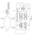
Figure 1 is a block diagram showing a configuration of a secondary battery controlling apparatus according to anembodiment 1 of the present invention; -
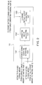
Figure 2 is a block diagram showing a configuration of a storage amount controlling part used for anembodiment 2 of the present invention; -
Figure 3 is a characteristic diagram showing a secondary battery controlling method according to theembodiment 2 of the present invention; and -
Figure 4 is a block diagram showing a configuration of a storage amount controlling part used for an embodiment 3 of the present invention. -
- 1 ... small-scaled power system, 2 ... secondary battery, 31 to 3n ... distributed power supply,
- 41 to 4m ... load system, 5 ... power supply and demand controlling apparatus, 6 ... power generation planning part of power supply and demand controlling apparatus,
- 7 ... planned storage amount estimating part of power supply and demand controlling apparatus, 8 ... actual output detecting part of power supply and demand controlling apparatus,
- 9 ... actual storage amount estimating part of power supply and demand controlling apparatus, 10 ... storage amount controlling part of power supply and demand controlling apparatus,
- 101 ... storage amount deviation estimating part of storage amount controlling part, 102 ... correction amount calculating part of storage amount controlling part,
- 103 ... secondary battery output instructing part of storage amount controlling part, 104 ... correction period adjusting part of storage amount controlling part
- Hereinafter, embodiments of the present invention are described with reference to the attached drawings.
- Initially, an
embodiment 1 of the present invention is described withFigure 1 . - In
Figure 1 , asecondary battery 2 anddistributed power supplies 31 to 3n are connected to a small-scaledpower system 1. Thedistributed power supplies 31 to 3n include an engine generator, a turbine generator, a power storing apparatus, a fuel cell and a natural energy generating apparatus. - Additionally,
load systems 41 to 4n are connected to the small-scaledpower system 1, and a power supply anddemand controlling apparatus 5 provides an output instruction to thesecondary battery 2 for controlling the small-scaledpower system 1. The power supply anddemand controlling apparatus 5 includes a powergeneration planning part 6, a planned storageamount estimating part 7, an actualoutput detecting part 8, an actual storageamount estimating part 9 and a storageamount controlling part 10. - In the
embodiment 1, the powergeneration planning part 6 of the power supply anddemand controlling apparatus 5 calculates a planned output value for a day of thedistributed power supplies 31 to 3n in the small-scaledpower system 1 including thesecondary battery 2 based on a past load power and output data such as a past track record of a power generation output in the distributed power supplies. - For example, a planned output value for a day every 30 minutes is calculated. The
distributed power supplies 31 to 3n are driven based on the planned output value calculated at the powergeneration planning part 6. The planned storageamount estimating part 7 estimates a planned storage amount with the passage of time from the planned output value of thesecondary battery 2 planned at the powergeneration planning part 6 by using a following formula (1). - The actual
output detecting part 8 detects a current actual output value of thesecondary battery 2 connected to the small-scaledpower system 1 by an active power detecting apparatus or the like, and transmits the detected value to the actual storageamount estimating part 9. The actual storageamount estimating part 9 estimates a current actual storage amount from the current output value of the secondary battery transmitted from the actualoutput detecting part 8 by using a following formula (2). - The estimated planned storage amount calculated at the planned storage
amount estimating part 7 and the estimated actual storage amount calculated at the actual storageamount estimating part 9 are transmitted to the storageamount controlling part 10 in a certain period, for example, every 10 minutes. When the estimated planned storage amount and the estimated actual storage amount are transmitted, the storageamount controlling part 10 calculates a difference between the estimated planned storage amount and the estimated actual storage amount, or a deviation of the storage amount, and calculates an output instruction correction value of the secondary battery such that the difference disappears after 10 minutes, for example. Then, the storageamount controlling part 10 provides a value obtained by adding the correction value to a secondary battery output instruction value from the powergeneration planning part 6 as an output instruction value of thesecondary battery 2, and thesecondary battery 2 is operated. - According to the
embodiment 1, the storage amount of the secondary battery can be maintained as planned because the difference (storage amount deviation) between the planned storage amount and the actual storage amount can be grasped and a signal adjusting an output instruction of the secondary can be generated so as to eliminate the storage amount deviation. - Next, an
embodiment 2 of the present invention is described withFigure 2 . Components same as theembodiment 1 have the same reference numerals and redundant description is omitted. - In
Figure 2 , the storageamount controlling part 10 has a storage amountdeviation estimating part 101, a correctionamount calculating part 102 and a secondary batteryoutput instructing part 103. - In the
embodiment 2 with this configuration, the storage amountdeviation estimating part 101 calculates a difference (storage amount deviation) between an estimated planned storage amount transmitted in n-minute period from the planned storageamount estimating part 7 and an estimated actual storage amount transmitted in the n-minute period from the actual storageamount estimating part 9 by using a following formula (3), as shown inFigure 3 .
- Here, in the case where the storage amount deviation occurs, a possibility arises in which the actual storage amount reaches a discharge end or a charge end as shown in
Figure 3 if an output of thesecondary battery 2 is further continued according to an instruction value from the powergeneration planning part 6. Thus, the correctionamount calculating part 102 calculates an output correction amount of the secondary battery for eliminating the storage amount deviation after n minute from a current storage amount deviation by using a following formula (4).
- The output instruction correction amount calculated at the correction
amount calculating part 102 is transmitted to the secondary batteryoutput instructing part 103. The secondary batteryoutput instructing part 103 provides thesecondary battery 2 with a value obtained by adding the output instruction correction amount to the secondary battery output instruction value of the powergeneration planning part 6 as an output instruction value to the secondary battery. - According to the
embodiment 2, accurate output correction is performed so that the storage amount deviation disappears every certain period, and therefore, the storage amount of the secondary battery can be controlled as planned. - Next, an embodiment 3 of the present invention is described with
Figure 4 . Components same as theembodiments - In
Figure 4 , the storageamount controlling part 10 of the power supply anddemand controlling apparatus 5 has the storage amountdeviation estimating part 101, the correctionamount calculating part 102, the secondary batteryoutput instructing part 103 and a correctionperiod adjusting part 104. - In the embodiment 3, the storage amount
deviation estimating part 101 transmits a difference between an estimated planned storage amount and an estimated actual storage amount, or a storage amount deviation to the correctionamount calculating part 102 and also to the correctionperiod adjusting part 104. The correctionperiod adjusting part 104 determines whether a period for correcting an output of the secondary battery is changed based on the storage amount deviation transmitted from the storage amountdeviation estimating part 101. - For example, if the storage amount deviation exceeds a threshold value set previously, the correction
period adjusting part 104 outputs a correction period so as to change it to m minute whose period is shorter than that of n minute. If the storage amount deviation is the threshold value or less, the correctionperiod adjusting part 104 outputs the correction period so as to set it n minute. - The correction period output from the correction
period adjusting part 104 is transmitted to the correctionamount calculating part 102 and the secondary batteryoutput instructing part 103. The correctionamount calculating part 102 calculates an output correction amount based on the correction period transmitted from the correctionperiod adjusting part 104 by using a following formula (5).
- Additionally, the secondary battery
output instructing part 103 is also operated so as to correct the secondary battery output instruction value of the powergeneration planning part 6 by the period transmitted from the correctionperiod adjusting part 104. - According to the embodiment 3, the actual storage amount can be controlled quickly back to the planned storage amount if the difference (storage amount deviation) between the planned storage amount and the actual storage amount is large.
- Next, an embodiment 4 of the present invention is described with Table 1. Components same as the embodiment 3 have the same reference numerals and redundant description is omitted.
- The correction
period adjusting part 104 used for the embodiment 3 has a function capable of setting a threshold value of the storage amount deviation and a correction period to any value when the correction period is changed depending on magnitude of the difference of the storage amount. For example, a plurality of change levels of the correction period can be set, as shown in Table 1. - The correction
period adjusting part 104 refers to a change reference table set previously and arbitrarily and selects a correction period based on the difference between the estimated planned storage amount and the estimated actual storage amount transmitted from the storage amountdeviation estimating part 101, and transmits the selected correction period to the correctionamount calculating part 102 and the secondary batteryoutput instructing part 103. - According to the embodiment 4, control with a high degree of freedom can be performed because a change of the correction period can be arbitrarily set depending on magnitude of the storage amount deviation.
- As described above, the present invention can maintain the storage amount of the secondary battery as planned because a difference between the planned storage amount and the actual storage amount can be grasped and a signal adjusting the secondary battery output instruction can be generated so as to eliminate the difference.
Claims (5)
- A power supply and demand controlling apparatus of a small-scaled power system including a distributed power supply including a secondary battery, characterized by comprising:a power generation planning part calculating a planned output value of the distributed power supply based on a past load power and track record data of a power generation output;a planned storage amount estimating part estimating a planned storage amount of the secondary battery from the planned output value;an actual output detecting part detecting an actual output value of the secondary battery;an actual storage amount estimating part estimating an actual storage amount from the actual output value of the secondary battery detected at the actual output detecting part; anda storage amount controlling part controlling the actual storage amount back to the planned storage amount if there is a difference between the planned storage amount and the actual storage amount.
- The secondary battery controlling apparatus according to claim 1, characterized in that the storage amount controlling part comprises:a storage amount deviation estimating part calculating a difference between the planned storage amount and the actual storage amount;a correction amount calculating part calculating an output correction amount of the secondary battery necessary for eliminating the storage amount deviation calculated at the storage amount deviation estimating part; anda secondary battery output instructing part outputting a value obtained by correcting the planned output value by the output correction amount as a second battery output instruction value.
- The secondary battery controlling apparatus according to claim 1, characterized in that the storage amount controlling part comprises:a correction period adjusting part changing a control period of the correction amount calculating part and the secondary battery output instructing part depending on a storage amount deviation output from the storage amount deviation estimating part.
- The secondary battery controlling apparatus according to claim 3, characterized in that the correction period adjusting part comprises:a change determination value setting function setting a determination reference for changing a correction period to any value depending on the storage amount deviation output from the storage amount deviation estimating part.
- A power supply and demand controlling method of a small-scaled power system including a distributed power supply including a secondary battery, characterized by comprising:calculating a planned output value of the distributed power supply based on a past load power and track record data of a power generation output;estimating a planned storage amount of the secondary battery from the planned output value;detecting an actual output value of the secondary battery;estimating an actual storage amount from the actual output value of the secondary battery; andcontrolling the actual storage amount back to the planned storage amount if there is a difference between the planned storage amount and the actual storage amount.
Applications Claiming Priority (2)
| Application Number | Priority Date | Filing Date | Title |
|---|---|---|---|
| JP2008201016A JP5011230B2 (en) | 2008-08-04 | 2008-08-04 | Secondary battery control device and control method |
| PCT/JP2008/067894 WO2010016158A1 (en) | 2008-08-04 | 2008-10-02 | Secondary battery control apparatus and control method |
Publications (2)
| Publication Number | Publication Date |
|---|---|
| EP2190096A1 true EP2190096A1 (en) | 2010-05-26 |
| EP2190096A4 EP2190096A4 (en) | 2016-11-09 |
Family
ID=41663387
Family Applications (1)
| Application Number | Title | Priority Date | Filing Date |
|---|---|---|---|
| EP08874332.3A Withdrawn EP2190096A4 (en) | 2008-08-04 | 2008-10-02 | SECONDARY BATTERY CONTROL APPARATUS AND CONTROL METHOD |
Country Status (7)
| Country | Link |
|---|---|
| US (1) | US8471528B2 (en) |
| EP (1) | EP2190096A4 (en) |
| JP (1) | JP5011230B2 (en) |
| CN (1) | CN101828314B (en) |
| MY (1) | MY154831A (en) |
| TW (1) | TWI369054B (en) |
| WO (1) | WO2010016158A1 (en) |
Cited By (2)
| Publication number | Priority date | Publication date | Assignee | Title |
|---|---|---|---|---|
| CN102893481A (en) * | 2010-07-30 | 2013-01-23 | 株式会社东芝 | Output distribution control apparatus |
| EP3229333A4 (en) * | 2014-12-02 | 2018-04-18 | Sekisui Chemical Co., Ltd. | Electric power control system, electric power control method, and program |
Families Citing this family (19)
| Publication number | Priority date | Publication date | Assignee | Title |
|---|---|---|---|---|
| JP5618511B2 (en) | 2009-09-08 | 2014-11-05 | 株式会社東芝 | Integrated monitoring and control system for smart grid and micro grid |
| JP2012039821A (en) * | 2010-08-10 | 2012-02-23 | Toshiba Corp | Power fluctuation relaxing device of power generating system and power fluctuation relaxing method |
| JP5807201B2 (en) * | 2010-12-28 | 2015-11-10 | パナソニックIpマネジメント株式会社 | Power control device |
| US9158300B2 (en) | 2011-06-30 | 2015-10-13 | Panasonic Corporation | Method for designing a control apparatus and control apparatus |
| US9010198B2 (en) * | 2011-07-29 | 2015-04-21 | United Technologies Corporation | Aircraft debris monitoring sensor assembly |
| CN102437566A (en) * | 2011-10-17 | 2012-05-02 | 中国电力科学研究院 | Adaptive Coordinated Control Method of Distributed Power Based on DC Bus Voltage |
| DE102012201969A1 (en) * | 2012-02-09 | 2013-08-14 | N-ERGIE Netz GmbH | Method for determining maximum electric energy of electric energy storage device, involves defining reproduced preset function and predefined function to satisfy preset formula for calculating absorbed electric maximum |
| US9407162B2 (en) * | 2012-05-24 | 2016-08-02 | Panasonic Corporation | Method for designing power controller, power controller, and power control device |
| JP5756566B2 (en) * | 2012-12-14 | 2015-07-29 | パナソニック株式会社 | Charge / discharge control method, charge / discharge control system, and charge / discharge control apparatus |
| JP6189092B2 (en) * | 2013-06-03 | 2017-08-30 | 東北電力株式会社 | Multi-purpose control device for grid storage battery |
| TWI484712B (en) * | 2013-07-01 | 2015-05-11 | Acbel Polytech Inc | Multi - mode current dispatching device |
| JP6123566B2 (en) * | 2013-08-12 | 2017-05-10 | 株式会社Ihi | Electricity supply and demand control method and apparatus |
| WO2015037307A1 (en) * | 2013-09-11 | 2015-03-19 | 株式会社東芝 | Power storage control device, management system, power storage control method, power storage control program, and memory medium |
| JP2016082617A (en) | 2014-10-10 | 2016-05-16 | 富士通株式会社 | Demand regulation plan generation device, demand regulation plan generation method, and demand regulation plan generation program |
| US9780567B2 (en) * | 2015-02-19 | 2017-10-03 | Cummins Power Generation Ip, Inc. | Energy storage system |
| US9812866B2 (en) | 2015-02-19 | 2017-11-07 | Cummins Power Generation Ip, Inc. | Energy storage system |
| JP2017034738A (en) * | 2015-07-28 | 2017-02-09 | 株式会社日立製作所 | Storage battery operation management apparatus and storage battery operation management method |
| CN110783963B (en) * | 2019-09-19 | 2021-06-22 | 广东电网有限责任公司广州供电局 | Power system optimal scheduling method, device, computer equipment and storage medium |
| JP2024164545A (en) * | 2023-05-15 | 2024-11-27 | 株式会社日立製作所 | Power management system and power control system |
Family Cites Families (19)
| Publication number | Priority date | Publication date | Assignee | Title |
|---|---|---|---|---|
| USRE39908E1 (en) * | 1993-12-27 | 2007-11-06 | Hitachi, Ltd. | Secondary battery power storage system |
| US5656915A (en) * | 1995-08-28 | 1997-08-12 | Eaves; Stephen S. | Multicell battery pack bilateral power distribution unit with individual cell monitoring and control |
| US6621250B1 (en) * | 1999-09-09 | 2003-09-16 | Toyota Jidosha Kabushiki Kaisha | Battery capacity measuring and remaining capacity calculating system |
| JP2001327083A (en) * | 2000-05-18 | 2001-11-22 | Ngk Insulators Ltd | Power storage and compensation system by high- temperature secondary battery |
| WO2002031954A1 (en) * | 2000-10-10 | 2002-04-18 | American Electric Power Company, Inc. | A power load-leveling system and packet electrical storage |
| JP3926114B2 (en) * | 2001-04-18 | 2007-06-06 | 株式会社マキタ | Management method of multiple charging devices |
| JP2004274981A (en) * | 2003-01-15 | 2004-09-30 | Sumitomo Electric Ind Ltd | Secondary battery control method, power supply system and communication device |
| JP3920263B2 (en) * | 2003-12-22 | 2007-05-30 | インターナショナル・ビジネス・マシーンズ・コーポレーション | Information processing apparatus, control method, program, and recording medium |
| JP2006042422A (en) * | 2004-07-22 | 2006-02-09 | Kansai Electric Power Co Inc:The | Power storage system |
| JP4254693B2 (en) * | 2004-11-08 | 2009-04-15 | トヨタ自動車株式会社 | Driving device and automobile equipped with the same |
| JP4256833B2 (en) * | 2004-11-10 | 2009-04-22 | 三菱重工業株式会社 | Power storage device and hybrid distributed power supply system |
| DE602006002896D1 (en) * | 2005-02-14 | 2008-11-13 | Denso Corp | Method and device for detecting the charging status of a secondary battery based on neural network calculation |
| US7274975B2 (en) * | 2005-06-06 | 2007-09-25 | Gridpoint, Inc. | Optimized energy management system |
| JP4566084B2 (en) * | 2005-07-21 | 2010-10-20 | 三洋電機株式会社 | Energy storage air conditioning system |
| KR101134894B1 (en) * | 2006-06-28 | 2012-04-13 | 엘지전자 주식회사 | Apparatus and method for detecting and displaying the remains of battery capacity |
| US7679334B2 (en) * | 2006-09-22 | 2010-03-16 | Panasonic Corporation | Power supply unit and electric apparatus |
| JP4969229B2 (en) * | 2006-12-18 | 2012-07-04 | 三菱重工業株式会社 | Power storage device and hybrid distributed power supply system |
| JP4796974B2 (en) * | 2007-01-26 | 2011-10-19 | 株式会社日立産機システム | Hybrid system of wind power generator and power storage device, wind power generation system, power control device |
| US7957921B2 (en) * | 2008-02-19 | 2011-06-07 | GM Global Technology Operations LLC | Model-based estimation of battery hysteresis |
-
2008
- 2008-08-04 JP JP2008201016A patent/JP5011230B2/en not_active Expired - Fee Related
- 2008-10-02 EP EP08874332.3A patent/EP2190096A4/en not_active Withdrawn
- 2008-10-02 US US12/602,219 patent/US8471528B2/en not_active Expired - Fee Related
- 2008-10-02 MY MYPI20095231A patent/MY154831A/en unknown
- 2008-10-02 CN CN2008801000247A patent/CN101828314B/en not_active Expired - Fee Related
- 2008-10-02 WO PCT/JP2008/067894 patent/WO2010016158A1/en not_active Ceased
- 2008-12-22 TW TW097150115A patent/TWI369054B/en not_active IP Right Cessation
Non-Patent Citations (1)
| Title |
|---|
| See references of WO2010016158A1 * |
Cited By (2)
| Publication number | Priority date | Publication date | Assignee | Title |
|---|---|---|---|---|
| CN102893481A (en) * | 2010-07-30 | 2013-01-23 | 株式会社东芝 | Output distribution control apparatus |
| EP3229333A4 (en) * | 2014-12-02 | 2018-04-18 | Sekisui Chemical Co., Ltd. | Electric power control system, electric power control method, and program |
Also Published As
| Publication number | Publication date |
|---|---|
| WO2010016158A1 (en) | 2010-02-11 |
| MY154831A (en) | 2015-07-31 |
| EP2190096A4 (en) | 2016-11-09 |
| TWI369054B (en) | 2012-07-21 |
| CN101828314A (en) | 2010-09-08 |
| CN101828314B (en) | 2013-02-06 |
| US8471528B2 (en) | 2013-06-25 |
| TW201008079A (en) | 2010-02-16 |
| JP2010041802A (en) | 2010-02-18 |
| US20100187907A1 (en) | 2010-07-29 |
| JP5011230B2 (en) | 2012-08-29 |
Similar Documents
| Publication | Publication Date | Title |
|---|---|---|
| US8471528B2 (en) | Secondary battery controlling apparatus and controlling method | |
| EP2065996A1 (en) | Power accumulator and hybrid distributed power supply system | |
| US20140324243A1 (en) | Method for delivering control power by using energy stores | |
| US8401712B2 (en) | Method for controlling distributed power sources | |
| US20140217989A1 (en) | Battery control system, battery controller, battery control method, and recording medium | |
| EP2546971B1 (en) | Photovoltaic generation system and power feeding system | |
| EP2696463A2 (en) | Wind power generation system, wind power generation control device and wind power generation control method | |
| EP2290779A1 (en) | Power supply/demand control device and power supply/demand control method | |
| JP5184202B2 (en) | Method for charging storage elements of an autonomous system | |
| EP2157654A1 (en) | Heater power supply method of sodium-sulfer battery | |
| EP2600482A1 (en) | Output distribution control apparatus | |
| EP2667476A1 (en) | Photovoltaic power generation system and power feeding system | |
| US20140309801A1 (en) | Method for providing control power for a power network | |
| CA2963441A1 (en) | Methods for operating a separate power supply system | |
| WO2012057307A1 (en) | Control device for power management | |
| US20230283077A1 (en) | Method for controlling a power supplied to an electrical network, implementing a power plant model | |
| WO2015111144A1 (en) | Power supply system and energy management system used in same | |
| US12476463B2 (en) | Power system adjusting device and power system adjusting program | |
| KR101299269B1 (en) | Battery Energy Storage System | |
| US9985467B2 (en) | Control device of power storage apparatus, wind power generation system, and control method of power storage apparatus | |
| EP2352214B1 (en) | Output power control apparatus | |
| EP2330711B1 (en) | Method for controlling interconnection system | |
| US12224588B2 (en) | Method for controlling a power supplied to an electrical network, with hybridization controller | |
| KR20190038093A (en) | Frequency control system | |
| Himawan et al. | Maximum penetration of intermittent renewable energy in southern sulawesi system based on primary reserve constrained unit commitment |
Legal Events
| Date | Code | Title | Description |
|---|---|---|---|
| PUAI | Public reference made under article 153(3) epc to a published international application that has entered the european phase |
Free format text: ORIGINAL CODE: 0009012 |
|
| 17P | Request for examination filed |
Effective date: 20091123 |
|
| AK | Designated contracting states |
Kind code of ref document: A1 Designated state(s): AT BE BG CH CY CZ DE DK EE ES FI FR GB GR HR HU IE IS IT LI LT LU LV MC MT NL NO PL PT RO SE SI SK TR |
|
| AX | Request for extension of the european patent |
Extension state: AL BA MK RS |
|
| DAX | Request for extension of the european patent (deleted) | ||
| RA4 | Supplementary search report drawn up and despatched (corrected) |
Effective date: 20161011 |
|
| RIC1 | Information provided on ipc code assigned before grant |
Ipc: H02J 3/32 20060101AFI20161005BHEP Ipc: H02J 3/46 20060101ALI20161005BHEP Ipc: H02J 3/38 20060101ALI20161005BHEP |
|
| STAA | Information on the status of an ep patent application or granted ep patent |
Free format text: STATUS: EXAMINATION IS IN PROGRESS |
|
| 17Q | First examination report despatched |
Effective date: 20190327 |
|
| STAA | Information on the status of an ep patent application or granted ep patent |
Free format text: STATUS: THE APPLICATION HAS BEEN WITHDRAWN |
|
| 18W | Application withdrawn |
Effective date: 20190806 |