EP2189975A1 - Active silencer and method of controlling active silencer - Google Patents
Active silencer and method of controlling active silencer Download PDFInfo
- Publication number
- EP2189975A1 EP2189975A1 EP07827812A EP07827812A EP2189975A1 EP 2189975 A1 EP2189975 A1 EP 2189975A1 EP 07827812 A EP07827812 A EP 07827812A EP 07827812 A EP07827812 A EP 07827812A EP 2189975 A1 EP2189975 A1 EP 2189975A1
- Authority
- EP
- European Patent Office
- Prior art keywords
- band
- signal
- sound
- bands
- remaining noise
- Prior art date
- Legal status (The legal status is an assumption and is not a legal conclusion. Google has not performed a legal analysis and makes no representation as to the accuracy of the status listed.)
- Withdrawn
Links
Images








Classifications
-
- G—PHYSICS
- G10—MUSICAL INSTRUMENTS; ACOUSTICS
- G10L—SPEECH ANALYSIS TECHNIQUES OR SPEECH SYNTHESIS; SPEECH RECOGNITION; SPEECH OR VOICE PROCESSING TECHNIQUES; SPEECH OR AUDIO CODING OR DECODING
- G10L21/00—Speech or voice signal processing techniques to produce another audible or non-audible signal, e.g. visual or tactile, in order to modify its quality or its intelligibility
- G10L21/02—Speech enhancement, e.g. noise reduction or echo cancellation
- G10L21/0208—Noise filtering
-
- G—PHYSICS
- G10—MUSICAL INSTRUMENTS; ACOUSTICS
- G10K—SOUND-PRODUCING DEVICES; METHODS OR DEVICES FOR PROTECTING AGAINST, OR FOR DAMPING, NOISE OR OTHER ACOUSTIC WAVES IN GENERAL; ACOUSTICS NOT OTHERWISE PROVIDED FOR
- G10K11/00—Methods or devices for transmitting, conducting or directing sound in general; Methods or devices for protecting against, or for damping, noise or other acoustic waves in general
- G10K11/16—Methods or devices for protecting against, or for damping, noise or other acoustic waves in general
- G10K11/175—Methods or devices for protecting against, or for damping, noise or other acoustic waves in general using interference effects; Masking sound
- G10K11/178—Methods or devices for protecting against, or for damping, noise or other acoustic waves in general using interference effects; Masking sound by electro-acoustically regenerating the original acoustic waves in anti-phase
- G10K11/1781—Methods or devices for protecting against, or for damping, noise or other acoustic waves in general using interference effects; Masking sound by electro-acoustically regenerating the original acoustic waves in anti-phase characterised by the analysis of input or output signals, e.g. frequency range, modes, transfer functions
- G10K11/17821—Methods or devices for protecting against, or for damping, noise or other acoustic waves in general using interference effects; Masking sound by electro-acoustically regenerating the original acoustic waves in anti-phase characterised by the analysis of input or output signals, e.g. frequency range, modes, transfer functions characterised by the analysis of the input signals only
- G10K11/17823—Reference signals, e.g. ambient acoustic environment
-
- G—PHYSICS
- G10—MUSICAL INSTRUMENTS; ACOUSTICS
- G10K—SOUND-PRODUCING DEVICES; METHODS OR DEVICES FOR PROTECTING AGAINST, OR FOR DAMPING, NOISE OR OTHER ACOUSTIC WAVES IN GENERAL; ACOUSTICS NOT OTHERWISE PROVIDED FOR
- G10K11/00—Methods or devices for transmitting, conducting or directing sound in general; Methods or devices for protecting against, or for damping, noise or other acoustic waves in general
- G10K11/16—Methods or devices for protecting against, or for damping, noise or other acoustic waves in general
- G10K11/175—Methods or devices for protecting against, or for damping, noise or other acoustic waves in general using interference effects; Masking sound
- G10K11/178—Methods or devices for protecting against, or for damping, noise or other acoustic waves in general using interference effects; Masking sound by electro-acoustically regenerating the original acoustic waves in anti-phase
- G10K11/1781—Methods or devices for protecting against, or for damping, noise or other acoustic waves in general using interference effects; Masking sound by electro-acoustically regenerating the original acoustic waves in anti-phase characterised by the analysis of input or output signals, e.g. frequency range, modes, transfer functions
- G10K11/17821—Methods or devices for protecting against, or for damping, noise or other acoustic waves in general using interference effects; Masking sound by electro-acoustically regenerating the original acoustic waves in anti-phase characterised by the analysis of input or output signals, e.g. frequency range, modes, transfer functions characterised by the analysis of the input signals only
- G10K11/17825—Error signals
-
- G—PHYSICS
- G10—MUSICAL INSTRUMENTS; ACOUSTICS
- G10K—SOUND-PRODUCING DEVICES; METHODS OR DEVICES FOR PROTECTING AGAINST, OR FOR DAMPING, NOISE OR OTHER ACOUSTIC WAVES IN GENERAL; ACOUSTICS NOT OTHERWISE PROVIDED FOR
- G10K11/00—Methods or devices for transmitting, conducting or directing sound in general; Methods or devices for protecting against, or for damping, noise or other acoustic waves in general
- G10K11/16—Methods or devices for protecting against, or for damping, noise or other acoustic waves in general
- G10K11/175—Methods or devices for protecting against, or for damping, noise or other acoustic waves in general using interference effects; Masking sound
- G10K11/178—Methods or devices for protecting against, or for damping, noise or other acoustic waves in general using interference effects; Masking sound by electro-acoustically regenerating the original acoustic waves in anti-phase
- G10K11/1785—Methods, e.g. algorithms; Devices
- G10K11/17853—Methods, e.g. algorithms; Devices of the filter
- G10K11/17854—Methods, e.g. algorithms; Devices of the filter the filter being an adaptive filter
-
- G—PHYSICS
- G10—MUSICAL INSTRUMENTS; ACOUSTICS
- G10K—SOUND-PRODUCING DEVICES; METHODS OR DEVICES FOR PROTECTING AGAINST, OR FOR DAMPING, NOISE OR OTHER ACOUSTIC WAVES IN GENERAL; ACOUSTICS NOT OTHERWISE PROVIDED FOR
- G10K11/00—Methods or devices for transmitting, conducting or directing sound in general; Methods or devices for protecting against, or for damping, noise or other acoustic waves in general
- G10K11/16—Methods or devices for protecting against, or for damping, noise or other acoustic waves in general
- G10K11/175—Methods or devices for protecting against, or for damping, noise or other acoustic waves in general using interference effects; Masking sound
- G10K11/178—Methods or devices for protecting against, or for damping, noise or other acoustic waves in general using interference effects; Masking sound by electro-acoustically regenerating the original acoustic waves in anti-phase
- G10K11/1787—General system configurations
- G10K11/17879—General system configurations using both a reference signal and an error signal
- G10K11/17881—General system configurations using both a reference signal and an error signal the reference signal being an acoustic signal, e.g. recorded with a microphone
-
- F—MECHANICAL ENGINEERING; LIGHTING; HEATING; WEAPONS; BLASTING
- F01—MACHINES OR ENGINES IN GENERAL; ENGINE PLANTS IN GENERAL; STEAM ENGINES
- F01N—GAS-FLOW SILENCERS OR EXHAUST APPARATUS FOR MACHINES OR ENGINES IN GENERAL; GAS-FLOW SILENCERS OR EXHAUST APPARATUS FOR INTERNAL-COMBUSTION ENGINES
- F01N1/00—Silencing apparatus characterised by method of silencing
- F01N1/06—Silencing apparatus characterised by method of silencing by using interference effect
- F01N1/065—Silencing apparatus characterised by method of silencing by using interference effect by using an active noise source, e.g. speakers
-
- G—PHYSICS
- G10—MUSICAL INSTRUMENTS; ACOUSTICS
- G10K—SOUND-PRODUCING DEVICES; METHODS OR DEVICES FOR PROTECTING AGAINST, OR FOR DAMPING, NOISE OR OTHER ACOUSTIC WAVES IN GENERAL; ACOUSTICS NOT OTHERWISE PROVIDED FOR
- G10K2210/00—Details of active noise control [ANC] covered by G10K11/178 but not provided for in any of its subgroups
- G10K2210/10—Applications
- G10K2210/12—Rooms, e.g. ANC inside a room, office, concert hall or automobile cabin
-
- G—PHYSICS
- G10—MUSICAL INSTRUMENTS; ACOUSTICS
- G10K—SOUND-PRODUCING DEVICES; METHODS OR DEVICES FOR PROTECTING AGAINST, OR FOR DAMPING, NOISE OR OTHER ACOUSTIC WAVES IN GENERAL; ACOUSTICS NOT OTHERWISE PROVIDED FOR
- G10K2210/00—Details of active noise control [ANC] covered by G10K11/178 but not provided for in any of its subgroups
- G10K2210/10—Applications
- G10K2210/128—Vehicles
- G10K2210/1282—Automobiles
-
- G—PHYSICS
- G10—MUSICAL INSTRUMENTS; ACOUSTICS
- G10K—SOUND-PRODUCING DEVICES; METHODS OR DEVICES FOR PROTECTING AGAINST, OR FOR DAMPING, NOISE OR OTHER ACOUSTIC WAVES IN GENERAL; ACOUSTICS NOT OTHERWISE PROVIDED FOR
- G10K2210/00—Details of active noise control [ANC] covered by G10K11/178 but not provided for in any of its subgroups
- G10K2210/30—Means
- G10K2210/301—Computational
- G10K2210/3025—Determination of spectrum characteristics, e.g. FFT
-
- G—PHYSICS
- G10—MUSICAL INSTRUMENTS; ACOUSTICS
- G10L—SPEECH ANALYSIS TECHNIQUES OR SPEECH SYNTHESIS; SPEECH RECOGNITION; SPEECH OR VOICE PROCESSING TECHNIQUES; SPEECH OR AUDIO CODING OR DECODING
- G10L21/00—Speech or voice signal processing techniques to produce another audible or non-audible signal, e.g. visual or tactile, in order to modify its quality or its intelligibility
- G10L21/02—Speech enhancement, e.g. noise reduction or echo cancellation
- G10L21/0208—Noise filtering
- G10L21/0216—Noise filtering characterised by the method used for estimating noise
- G10L21/0232—Processing in the frequency domain
Definitions
- the present invention relates to an active silencer and a method for controlling the active silencer.
- ANC Active noise control
- the ANC is the technology of silencing noise by interfering with noise using sound waves (control sound) with an equal amplitude and an inverse phase.
- an active silencer is used to silence noise of an air-conditioner, in a factory, in a vehicle, etc.
- the patent document 1 discloses an active silencer having high silencing performance with low computational complexity.
- the active silencer is configured by a sensor microphone 101, an FIR filter 102 that can be set with a variable filter coefficient, an FIR filter 103 with a fixed filter coefficient, an LMS arithmetic unit 104 provided at the stage after the FIR filter 103, a controlling speaker 105, and an error microphone 106 as illustrated in FIG. 11 .
- An adaptive filter 107 is configured by the FIR filter 102, the FIR filter 103, and the LMS (least mean square) arithmetic unit 104.
- the sensor microphone 101 detects a signal (reference signal) corresponding to noise, and outputs the signal to the FIR filter 102 that can be set with a variable filter coefficient and the FIR filter 103 having a fixed filter coefficient.
- the FIR filter (filter of an error path) 103 having a fixed coefficient holds input reference signals x(t) both at the current time and in the past for the number of its taps.
- r t w ⁇ ⁇ * x ⁇ t *(* indicates a convolution arithmetic.)
- e (t) is a remaining noise signal detected by the error microphone 106 at the time t, and ⁇ indicates a step size parameter.
- a Filtered-X LMS algorithm is obtained by adding the FIR filter 103 with a fixed coefficient at the stage before the LMS arithmetic unit 104 in the adaptive filter 107.
- the basic principle of the algorithm is to update (determine) the filter coefficient of the FIR filter 102 in the steepest descent method to decrease remaining noise by considering the transfer function from the controlling speaker 105 to the error microphone 106.
- the Filtered-X LMS algorithm is described in, for example, the non-patent document 1.
- an adaptive algorithm for a time area such as the Filtered-X LMS algorithm etc.
- an amount of silenced noise is larger in a frequency band at a higher sound pressure level. Accordingly, there is the problem that an effective silencing effect cannot be obtained when there is disagreeable noise for humans in a frequency band at a low sound pressure level.
- the reference signal x from a sensor microphone 111 is divided into a plurality of bands x 1 , x 2 , ..., x n through a band division unit 112 as illustrated in FIG. 12 , and the remaining noise signal e from an error microphone 116 is divided into a plurality of bands e 1 , e 2 , ..., e n through a band division unit 114.
- an adaptive filter unit 113 having a plurality of adaptive filters, a filter coefficient is updated (determined) for each band and a control signal to be output to a controlling speaker 115 is generated.
- a sufficient amount of silenced noise may not be acquired at some frequencies due to the aging of a controlling speaker and a microphone, the fluctuation of the spatial transmission system of an error path from a controlling speaker to an error microphone, disturbance noise mixed into the active silencer, etc.
- the present invention aims at providing an active silencer capable of avoiding outstanding noise caused by a non-silenced band, and a method for controlling the active silencer.
- the active silencer according to a first aspect of the present invention includes: a speaker to generate control sound which interferes with noise; a microphone to detect noise remaining after the interference as a remaining noise signal; a sound quality evaluation unit to evaluate the sound quality of the remaining noise and outputting a result of the sound quality evaluation; an actuation signal determination unit to determine, according to the result of the sound quality evaluation, the detection timing of the frequency component of the remaining noise signal to be used when the control sound is generated for a plurality of bands of the remaining noise, corresponding to the plurality of bands of a reference signal corresponding to the noise; and a control signal generation unit to generate and output a control signal for generation of the control sound depending on a plurality of bands of the determined remaining noise signal and a plurality of bands of the reference signal corresponding to the noise.
- the detection timing of a frequency component to be used when the control sound of a speaker is generated is determined by the actuation signal determination unit depending on the result of a sound quality evaluation for each band of the remaining noise signal.
- the frequency component of the current band is excessively erased as compared with an adjacent lower frequency band, or as compared with an adjacent higher frequency band, then it is possible to prevent the difference between the sound pressure level of the remaining noise of the current band and the sound pressure level of the band of one of the adjacent bands or the bands of the adjacent bands from developing not to use the frequency component detected at the current time on the current band when a control sound is generated. Therefore, for example, it is possible to avoid a non-silenced band from becoming outstandingly noisy.
- the active silencer according to the second aspect is based on the first aspect.
- the actuation signal determination unit includes a first band division unit to divide the remaining noise signal into a plurality of frequency bands, and a switch unit having a plurality of switches for determining whether or not the frequency component of each band of the remaining noise signal detected at the current time is to be passed through the control signal generation unit depending on the result of the sound quality evaluation.
- the control signal generation unit includes a second band division unit to divide the reference signal into a plurality of bands corresponding to a plurality of bands of the remaining noise, an adaptive filter unit provided with a plurality of adaptive filters having a variable filter coefficient for filtering the frequency component of the reference signal detected at the current time and generating a second control signal for each corresponding band of the remaining noise signal and the reference signal so that the frequency component which has passed through the switch can be reduced, and an adder to obtain a sum of the second control signal, generating the control signal, and outputting the signal to the speaker.
- the active silencer is based on the second aspect.
- the sound quality evaluation unit calculates the difference in the sound pressure levels between the adjacent bands of the remaining noise signal.
- the actuation signal determination unit controls the switch not to pass the frequency component of the remaining noise signal of the current band when the sound pressure level of the current band is equal to or smaller than a predetermined value than the sound pressure level of a lower adjacent band, or when the sound pressure level of the current band is equal to or smaller than a predetermined value than the sound pressure level of a higher adjacent band.
- the active silencer according to the fourth aspect of the present invention is based on the third aspect, and further includes a threshold change unit for changing the threshold depending on the sound pressure level for each band of the remaining noise signal.
- the threshold change unit changes the threshold to be used in determining a band into a smaller value if the sound pressure level of the band is equal to or larger than a predetermined value when the sound pressure level of the remaining noise is outstanding in the band, and changes the threshold to be used in determining a band into a larger value if the sound pressure level of the band is smaller than the predetermined value when the sound pressure level of the remaining noise is outstanding in the band.
- the threshold change unit changes the threshold to be used in determining a band into a smaller value when the band having an outstanding sound pressure level of the remaining noise refers to high sensitivity to human ears.
- control can be performed to improve the silencing performance while suppressing the generation of noisy sound (unusual sound).
- FIG. 1 is a configuration according to the principle of the active silencer of the present invention. As illustrated in FIG. 1 , the active silencer is configured by a controlling speaker 2, an error microphone 3, a sound quality evaluation unit 5, an actuation signal determination unit 4, and a control signal generation unit 1.
- the controlling speaker 2 and the controlling speaker 2 are provided near an area on which the silencer is to work.
- the controlling speaker 2 generates control sound which interferes with noise.
- the error microphone 3 detects the noise remaining after the interference.
- the sound quality evaluation unit 5 extracts the sound quality of the remaining noise and outputs a result of a sound quality evaluation.
- the actuation signal determination unit 4 determines the detection timing of the frequency component of the remaining noise signal to be used in generating the control sound for a plurality of bands of the remaining noise corresponding to the plurality of bands of the reference signal corresponding to the noise depending on the result of the sound quality evaluation.
- the control signal generation unit 1 generates and outputs a control signal for generation of the control sound on the basis of the plurality of bands of the determined remaining noise signal, and the plurality of bands of the reference signal corresponding to the noise.
- FIG. 2 is a configuration of the active silencer according to the first embodiment of the present invention.
- the active silencer according to the first embodiment is configured by a sensor microphone 11, a control signal generation unit 15, a controlling speaker 24, an actuation signal determination unit 18, an error microphone 25, and a sound quality evaluation unit 23.
- the sensor microphone 11 detects a reference signal corresponding to noise.
- the control signal generation unit 15 is provided with: a band division unit configured by eight band pass filters (hereinafter referred to as a BPF), that is, BPFs 12-1, 12-2, ..., and 12-8, for dividing a signal corresponding to the noise detected by the sensor microphone 11 into eight predetermined bands; an adaptive filter unit configured by eight adaptive filters, that is, adaptive filters 13-1, 13-2, ..., and 13-8, for filtering each of the divided bands; and an adder 14 for adding up the output of the respective adaptive filters.
- a band division unit configured by eight band pass filters (hereinafter referred to as a BPF), that is, BPFs 12-1, 12-2, ..., and 12-8, for dividing a signal corresponding to the noise detected by the sensor microphone 11 into eight predetermined bands
- an adaptive filter unit configured by eight adaptive filters, that is, adaptive filters 13-1, 13-2, ..., and 13-8, for filtering each of the divided bands
- an adder 14 for
- the error microphone 25 detects remaining noise remaining after the control sound emitted by the controlling speaker 24 interferes with noise.
- the sound quality evaluation unit 23 is provided with: a band division unit configured by eight band pass filters, that is, BPFs 22-1, 22-2, ..., and 22-8, for dividing a remaining noise signal detected by the error microphone 25 into eight predetermined bands; and an inter-adjacent-band level difference calculation unit (of a remaining noise signal) configured by a level difference calculation unit 21-1 for calculating a level difference between output of the BPF 22-1 and output of the BPF 22-2; a level difference calculation unit 21-2 for calculating a level difference between output of the BPF 22-2 and output of the BPF 22-3; ...; and a level difference calculation unit 21-7 for calculating a level difference between output of the BPF 22-7 and output of the BPF 22-8.
- a band division unit configured by eight band pass filters, that is, BPFs 22-1, 22-2, ..., and 22-8, for dividing a remaining noise signal
- the actuation signal determination unit 18 is provided with: a band division unit configured by the above-mentioned BPFs 22-1, 22-2, ..., and 22-8; and a switch unit having a plurality of switches 16-1, 16-2, ..., and 16-8 for comparing the calculated sound pressure level difference between the bands with a corresponding threshold in a plurality of thresholds TH 1 through TH 7 stored in a threshold storage unit 17, and determining whether or not the output of the BPFs 22-1, 22-2, ..., and 22-8 is to be transmitted to the adaptive filters 13-1, 13-2, ..., and 13-8 at the current time.
- the active silencer in FIG. 2 performs in parallel the operation by the control signal generation unit 15 for processing a reference signal corresponding to the noise detected by the sensor microphone 11 and the operation of the sound quality evaluation unit 23 and the actuation signal determination unit 18 for processing the remaining noise signal detected by the error microphone 25.
- the adaptive filters 13-1, 13-2, ..., and 13-8 when the filter coefficients h 1 ⁇ (t), h 2 ⁇ (t), ..., h 8 ⁇ (t) are updated, the frequency components corresponding to the reference signal and the remaining noise signal detected at the same time are used in an arithmetic operation.
- step S9 of the flow of steps S1 ⁇ S3 ⁇ S5 ⁇ S9 and the flow of steps S2 ⁇ S4 ⁇ S6 S8 ⁇ S9.
- step S1 in FIG. 3 the sensor microphone 11 detects a reference signal x(t).
- FIG. 4 illustrates the detailed configuration of each adaptive filter illustrated in FIG. 2 .
- an adaptive filter 29 is configured by an LMS arithmetic unit 27 for performing an arithmetic operation on the basis of the LMS algorithm, a FIR filter 26 provided at the stage preceding the LMS arithmetic unit 27 and having a fixed filter coefficient, and a FIR filter 28 for which a variable filter coefficient can be set.
- h i ⁇ ⁇ t + 1 h i ⁇ t + ⁇ ⁇ e i t ⁇ r i ⁇ t
- e i (t) indicates the i-th frequency component of the band-divided remaining noise signal detected by the error microphone 106 at the time t
- ⁇ indicates a step size parameter
- the adder 14 Upon receipt of the output of each adaptive filter, the adder 14 obtains a sum by the following equation (6), and outputs the sum as a control signal to the controlling speaker 24.
- a control signal is generated in step S5 after step S3 by the adaptive filters 13-1, 13-2, ..., and 13-8 and the adder 14 as described with reference to FIG. 4 above, and output to the controlling speaker 24.
- the controlling speaker 24 generates control sound on the basis of the control signal. Then, control is passed to step S9.
- the remaining noise signal e (t) is detected by the error microphone 25 in step S2.
- the detected remaining noise signal e(t) is input to the band pass filters (BPF) 22-1, 22-2, ..., and 22-8, and the band is divided into eight sections.
- FIG. 5 illustrates the detailed configuration of each level difference calculation unit illustrated in FIG. 2 .
- a multiplexer 31 calculates the square of e i (t) ( ⁇ e i (t) ⁇ 2 ) from e i (t).
- Delay units 33-1, 33-2, ..., and 33-Te respectively latch the value at the current time and at each time in the past, that is, ⁇ e i (t) ⁇ 2 , ⁇ e i (t-1) ⁇ 2 , ..., ⁇ e i (t-Te) ⁇ 2 .
- An adder 35-1 adds ⁇ e i (t) ⁇ 2 and e i (t-1)) 2 , ..., an adder 35-(Te-1) adds a result of the addition of an adder 35-(Te-2) to ⁇ e i (t-Te+1) ⁇ 2 , and an adder 35-Te adds a result of the addition of the adder 35-(Te-1) to ⁇ e i (t-Te) ⁇ 2e .
- a multiplexer 32 calculates the square of e i+1 (t) ( ⁇ e i+1 (t) ⁇ 2 ) from e i+1 (t).
- Delay units 34-1, 34-2, ..., and 34-Te respectively latch the value at the current time and at each time in the past, that is, ⁇ e i+1 (t) ⁇ 2 , ⁇ e i+1 (t-1) ⁇ 2 , ..., ⁇ e i+1 (t-Te) ⁇ 2 .
- An adder 36-1 adds ⁇ e i+1 (t) ⁇ 2 and ⁇ e i+1 (t-1) ⁇ 2 , ..., an adder 36-(Te-1) adds a result of the addition of an adder 36-(Te-2) to ⁇ e i+1 (t-Te+1) ⁇ 2 , and an adder 36-Te adds a result of the addition of the adder 36-(Te-1) to ⁇ e i+1 (t-Te) ⁇ 2 .
- An adder 37 subtracts the output of the adder 36-Te from the output of the adder 35-Te.
- the output of the adder 37 is assigned by the following equation (8).
- step S6 after step S4 back in FIG. 3 , the (sound pressure) level difference between the adjacent bands of the remaining noise signal is calculated as described above with reference to FIG. 5 .
- step S8 it is determined whether or not the frequency component is to be passed through each of the bands of the remaining noise signal depending on whether or not the switches 16-1, 16-2, ..., and 16-8 are to be conducting.
- FIG. 6A illustrates the detailed configuration of any of the switches 16-2, ..., and 16-7 in FIG. 2 .
- a determination unit 42 determines whether or not -d i (t) obtained by inverting the sign of the sound pressure level difference d i (t) is larger than the threshold TH i , and a determination unit 43 determines whether or not the sound pressure level difference d i-1 (t) is larger than the threshold TH i-1 .
- the OR arithmetic unit 44 outputs a signal for disabling the switch 41 to be conducting when the determination unit 42 issues a signal indicating that -di(t) is larger than the threshold TH 1 , or the determination unit 43 issues a signal indicating that -d i-1 (t) is larger than the threshold TH i-1 .
- FIG. 6B illustrates the detailed configuration of the switch 16-1 illustrated in FIG. 2 .
- a switch 46 determines whether or not the remaining noise signal e 1 (t) is to be conducting depending on the output of a determination unit 47.
- the determination unit 47 determines whether or not -d 1 (t) obtained by inverting the sign of the sound pressure level difference d 1 (t) is larger than the threshold TH 1 . If it is determined that -d 1 (t) is larger than the threshold TH 1 , it outputs a signal for disabling the switch 46 to be conducting.
- FIG. 6C illustrates the detailed configuration of the switch 16-8 illustrated in FIG. 2 .
- a switch 48 determines whether or not the remaining noise signal e 8 (t) depending on the output of a determination unit 49.
- the determination unit 49 determines whether or not the sound pressure level difference d 7 (t) is larger than the threshold TH 8 . If it is determined that d 7 (t) is larger than the threshold TH 7 , the unit outputs a signal for disabling the switch 48 to be conducting.
- step S8 illustrated in FIG. 3 it is determined whether or not a frequency component is to be passed through each band of a remaining noise signal by the following equations (9) through (11).
- the filter coefficient h i+1 ⁇ (t) of each adaptive filter at the next time point (t + 1) is obtained by the equation (5) described above with reference to FIG. 4 on the basis of the frequency component x i (t) of each band of the reference signal x(t), e' i (t) obtained from the frequency component e i (t) of each band of the remaining noise signal e(t), and the filter coefficient h i ⁇ (t) of each adaptive filter at the current time t.
- FIG. 7 illustrates the sound pressure level of each band at the initial stage, and the sound pressure level of each band after the activation of the active silencer according to the present invention.
- FIG. 7 illustrates, for example, the sound pressure level of the bands passed through by the BPFs 22-1, 22-2, ..., and 22-8 in order from the rightmost.
- the sound pressure level of the band passed through by the BPF 22-5 is outstanding, and the band corresponds to the non-silenced band.
- the sound pressure level of each frequency band of the remaining noise is initially flat, and after some time has passed with the active silencer according to the first embodiment operated, the occurs differences in silencing performance among the bands.
- the frequency component detected at the current time is prevented from being output to the adaptive filter on the current band.
- the filter coefficient of the adaptive filter corresponding to the current band is not updated from the time point when the threshold is exceeded, and the frequency component of the current band is no more erased according to the remaining noise signal. Therefore, each band can be silenced while preventing the development of the difference between the sound pressure level of the remaining noise of the current band and the sound pressure level of the band of one of the adjacent bands or the sound pressure levels of both of the adjacent bands, thereby protecting the non-silenced band from sounding noisy.
- a non-silenced band is included in the bands to be passed through one BPF.
- the method by the equations (9) through (11) according to the first embodiment is effective.
- the configurations of the devices are different in the spectrum continuity evaluating portion of remaining noise between the first and second embodiments.
- remaining noise is divided into a plurality of bands using a plurality of band pass filters, and the sound pressure level difference between adjacent bands are calculated.
- the frequency of remaining noise is analyzed, and the sound pressure level difference between the bands is calculated using the power spectrum calculated on the basis of the result of the frequency analysis.
- FIG. 8 is a configuration of the active silencer according to the second embodiment of the present invention.
- the sound quality evaluation unit 54 includes a fast Fourier transform processing unit (FFT processing unit) 51, a power spectrum calculation unit 52, and an inter-band level difference calculation unit 53.
- FFT processing unit fast Fourier transform processing unit
- power spectrum calculation unit 52 power spectrum calculation unit
- inter-band level difference calculation unit 53 inter-band level difference calculation unit 53.
- the fast Fourier transform processing unit 51 analyzes the frequency of the remaining noise signal e (t) from the error microphone 25.
- the power spectrum calculation unit 52 calculates the power spectrum on the basis of the result obtained by the frequency analysis.
- the inter-band level difference calculation unit 53 calculates the difference of the sound pressure level between the adjacent bands in a plurality of bands passed by a plurality of BPSs provided in the actuation signal determination unit 18 on the basis of the calculated power spectrum.
- the calculated level differences d 1 (t) to d 7 (t) between the adjacent bands are output to the actuation signal determination unit 18.
- the subsequent operations are the same as those according to the first embodiment. Described next is the third embodiment.
- FIG. 9 is a configuration of the active silencer according to the third embodiment of the present invention.
- a threshold change unit 57 for dynamically changing a threshold for determination of the continuous spectrum of remaining noise is added to the configuration illustrated in FIG. 2 .
- FIG. 10 illustrates the detailed configuration of the threshold change unit in FIG. 9 .
- the threshold change unit 57 is configured by BPF 61-1, ..., and BPF 61-8, level calculation units 62-1, ..., and level difference calculation unit 62-8, a maximal band determination unit 64, and a threshold estimate unit 63.
- the BPF 61-1, ..., and BPF 61-8 divide the remaining noise signal e (t) from the error microphone 25 into eight bands corresponding to the eight BPFs of the actuation signal determination unit 56.
- the level calculation units 62-1, ..., and level difference calculation unit 62-8 respectively input the band components e 1 (t), ..., e 8 (t) of the remaining noise signal, and calculate the average value of the band components for Te hours , thereby obtaining the average value of the sound pressure level of each band.
- the square of e i (t) ( ⁇ e i (t) ⁇ 2 ) is calculated from the input e i (t).
- the output Bl i of the level calculation unit 62-i can be obtained by the following equation (12).
- the maximal band determination unit 64 inputs the output b1 1 , ..., b1 8 of the level calculation units 62-1, ..., and level difference calculation unit 62-8 as the sound pressure levels of the respective bands, compares the sound pressure levels of the respective bands, determines a band (maximal band) having a higher sound pressure level than the surrounding bands, and outputs the inter-band numbers b1, b2, ... indicating both ends of the band determined as the maximal band to the threshold estimate unit 63.
- the threshold estimate unit 63 changes the values of the thresholds TH b1 , TH b2 , ... corresponding to the inter-band numbers b1, b2, ... from the maximal band determination unit 64, and outputs the resultant values to the threshold storage unit 17 in the actuation signal determination unit 18 illustrated in FIG. 9 .
- a threshold is changed as follows.
- the silencing performance can be enhanced without generating noisy sound (unusual sound) even when a hardly-silenced ban is changed by the ambient noise or the surrounding environment of the active silencer in the first method.
- a threshold is changed as follows in the second method.
- the threshold for the band is set as a smaller value.
Landscapes
- Engineering & Computer Science (AREA)
- Physics & Mathematics (AREA)
- Acoustics & Sound (AREA)
- Multimedia (AREA)
- Computational Linguistics (AREA)
- Quality & Reliability (AREA)
- Signal Processing (AREA)
- Health & Medical Sciences (AREA)
- Audiology, Speech & Language Pathology (AREA)
- Human Computer Interaction (AREA)
- Soundproofing, Sound Blocking, And Sound Damping (AREA)
- Exhaust Silencers (AREA)
Abstract
Description
- The present invention relates to an active silencer and a method for controlling the active silencer.
- Active noise control (ANC) is one of the techniques for silencing noise. The ANC is the technology of silencing noise by interfering with noise using sound waves (control sound) with an equal amplitude and an inverse phase.
Recently, an active silencer is used to silence noise of an air-conditioner, in a factory, in a vehicle, etc. - Described below are typical conventional active silencers.
Thepatent document 1 discloses an active silencer having high silencing performance with low computational complexity. The active silencer is configured by asensor microphone 101, anFIR filter 102 that can be set with a variable filter coefficient, anFIR filter 103 with a fixed filter coefficient, an LMSarithmetic unit 104 provided at the stage after theFIR filter 103, a controllingspeaker 105, and anerror microphone 106 as illustrated inFIG. 11 . Anadaptive filter 107 is configured by theFIR filter 102, theFIR filter 103, and the LMS (least mean square)arithmetic unit 104. - The
sensor microphone 101 detects a signal (reference signal) corresponding to noise, and outputs the signal to theFIR filter 102 that can be set with a variable filter coefficient and theFIR filter 103 having a fixed filter coefficient. - The FIR filter (filter of an error path) 103 having a fixed coefficient holds input reference signals x(t) both at the current time and in the past for the number of its taps. The signal (filter reference signal) r(t) obtained by convoluting the propagation function w^→ = [w^(1), w^(2), ..., w^(Nw)] of the error path from the controlling
speaker 105 to theerror microphone 106 to the x→(t) = [x(t), x(t-1), ..., x(t-Nw+1)] obtained by expressing the reference signal x (t) by vector by the following equation (1).
*(* indicates a convolution arithmetic.) - The LMS
arithmetic unit 104 holds the input reference signals r(t) input from theFIR filter 103 both at the current time and in the past for the number (Nh) of the taps of theFIR filter 102. Then, the coefficient h→(t+1) = [h(1, t+1), h(2, t+1), ..., h(Nh, t+1)] of theFIR filter 102 at the next time point is obtained by the following equation (2) using r→(t) = [r(t), r(t-1), ..., r(t-Nh+1)] obtained by expressing the filter reference signal by vector, and the coefficient h→(t)=[h(1, t), h (2, t), ..., h(Nh, t) of theFIR filter 102 at the current time
- However, e (t) is a remaining noise signal detected by the
error microphone 106 at the time t, and µ indicates a step size parameter. - As illustrated in
FIG. 11 , and as compared with an LMS algorithm, a Filtered-X LMS algorithm is obtained by adding theFIR filter 103 with a fixed coefficient at the stage before the LMSarithmetic unit 104 in theadaptive filter 107. The basic principle of the algorithm is to update (determine) the filter coefficient of theFIR filter 102 in the steepest descent method to decrease remaining noise by considering the transfer function from the controllingspeaker 105 to theerror microphone 106. - The Filtered-X LMS algorithm is described in, for example, the
non-patent document 1.
Generally, in an adaptive algorithm for a time area such as the Filtered-X LMS algorithm etc., an amount of silenced noise is larger in a frequency band at a higher sound pressure level. Accordingly, there is the problem that an effective silencing effect cannot be obtained when there is disagreeable noise for humans in a frequency band at a low sound pressure level. - To solve the problem, in the
patent document 2, the reference signal x from asensor microphone 111 is divided into a plurality of bands x1, x2, ..., xn through aband division unit 112 as illustrated inFIG. 12 , and the remaining noise signal e from anerror microphone 116 is divided into a plurality of bands e1, e2, ..., en through aband division unit 114. In anadaptive filter unit 113 having a plurality of adaptive filters, a filter coefficient is updated (determined) for each band and a control signal to be output to a controllingspeaker 115 is generated. Thus, a high silencing effect is obtained in a wide frequency band. - However, in the active silencer, a sufficient amount of silenced noise may not be acquired at some frequencies due to the aging of a controlling speaker and a microphone, the fluctuation of the spatial transmission system of an error path from a controlling speaker to an error microphone, disturbance noise mixed into the active silencer, etc.
- In this case, there is a larger difference between a sound pressure level of a frequency band at which a sufficient amount of silenced noise can be obtained and a sound pressure level of a frequency band at which a sufficient amount of silenced noise can be obtained. As a result, as illustrated in
FIG. 13 , there can be the problem that a sound pressure level in each frequency band that is initially flat becomes partially outstanding as a non-silenced band after the sufficient lapse of time when the active silencer operates, thereby generating noisy sound with an outstanding non-silenced band. - In addition, when a filter coefficient is updated (determined) independently for each divided band (for example, in the case in
FIG. 12 ), there occurs a more obvious problem in which it sounds exceedingly noisy in a non-silenced band. - Patent Document 1: Japanese Patent Publication No.
2872545 - Patent Document 2: Japanese Patent Publication No.
2517150 - Non-patent Document 1: B. Widrow and S. Stearns, "Adoptive Signal Processing", Prentice-Hall, Englewood, Cliffs, NJ, 1985
- The present invention aims at providing an active silencer capable of avoiding outstanding noise caused by a non-silenced band, and a method for controlling the active silencer.
The active silencer according to a first aspect of the present invention includes: a speaker to generate control sound which interferes with noise; a microphone to detect noise remaining after the interference as a remaining noise signal; a sound quality evaluation unit to evaluate the sound quality of the remaining noise and outputting a result of the sound quality evaluation; an actuation signal determination unit to determine, according to the result of the sound quality evaluation, the detection timing of the frequency component of the remaining noise signal to be used when the control sound is generated for a plurality of bands of the remaining noise, corresponding to the plurality of bands of a reference signal corresponding to the noise; and a control signal generation unit to generate and output a control signal for generation of the control sound depending on a plurality of bands of the determined remaining noise signal and a plurality of bands of the reference signal corresponding to the noise. - The detection timing of a frequency component to be used when the control sound of a speaker is generated is determined by the actuation signal determination unit depending on the result of a sound quality evaluation for each band of the remaining noise signal.
- Therefore, for example, if the frequency component of the current band is excessively erased as compared with an adjacent lower frequency band, or as compared with an adjacent higher frequency band, then it is possible to prevent the difference between the sound pressure level of the remaining noise of the current band and the sound pressure level of the band of one of the adjacent bands or the bands of the adjacent bands from developing not to use the frequency component detected at the current time on the current band when a control sound is generated. Therefore, for example, it is possible to avoid a non-silenced band from becoming outstandingly noisy.
- The active silencer according to the second aspect is based on the first aspect. The actuation signal determination unit includes a first band division unit to divide the remaining noise signal into a plurality of frequency bands, and a switch unit having a plurality of switches for determining whether or not the frequency component of each band of the remaining noise signal detected at the current time is to be passed through the control signal generation unit depending on the result of the sound quality evaluation. The control signal generation unit includes a second band division unit to divide the reference signal into a plurality of bands corresponding to a plurality of bands of the remaining noise, an adaptive filter unit provided with a plurality of adaptive filters having a variable filter coefficient for filtering the frequency component of the reference signal detected at the current time and generating a second control signal for each corresponding band of the remaining noise signal and the reference signal so that the frequency component which has passed through the switch can be reduced, and an adder to obtain a sum of the second control signal, generating the control signal, and outputting the signal to the speaker.
- The active silencer according to the third aspect of the present invention is based on the second aspect. The sound quality evaluation unit calculates the difference in the sound pressure levels between the adjacent bands of the remaining noise signal. The actuation signal determination unit controls the switch not to pass the frequency component of the remaining noise signal of the current band when the sound pressure level of the current band is equal to or smaller than a predetermined value than the sound pressure level of a lower adjacent band, or when the sound pressure level of the current band is equal to or smaller than a predetermined value than the sound pressure level of a higher adjacent band.
- The active silencer according to the fourth aspect of the present invention is based on the third aspect, and further includes a threshold change unit for changing the threshold depending on the sound pressure level for each band of the remaining noise signal.
- For example, the threshold change unit changes the threshold to be used in determining a band into a smaller value if the sound pressure level of the band is equal to or larger than a predetermined value when the sound pressure level of the remaining noise is outstanding in the band, and changes the threshold to be used in determining a band into a larger value if the sound pressure level of the band is smaller than the predetermined value when the sound pressure level of the remaining noise is outstanding in the band. With the configuration, when the remaining noise easily becomes noisy, the update of a filter coefficient for each divided band can be controlled so that a discontinuous spectrum cannot occur, and when the remaining noise does not easily become noisy, the update of a filter coefficient for each divided band can be controlled so that silencing performance can be improved.
- In addition, for example, the threshold change unit changes the threshold to be used in determining a band into a smaller value when the band having an outstanding sound pressure level of the remaining noise refers to high sensitivity to human ears. With the configuration, control can be performed to improve the silencing performance while suppressing the generation of noisy sound (unusual sound).
- According to the present invention, outstanding noise in a non-silenced band can be avoided.
-
-
FIG. 1 is a configuration according to the principle of the active silencer of the present invention; -
FIG. 2 is a configuration of the active silencer according to the first embodiment of the present invention; -
FIG. 3 is a flowchart of the operation of the active silencer according to the first embodiment of the present invention; -
FIG. 4 illustrates the detailed configuration of each adaptive filter illustrated inFIG. 2 ; -
FIG. 5 illustrates the detailed configuration of each level difference calculation unit illustrated inFIG. 2 ; -
FIG. 6A illustrates the detailed configuration of any of the switches 16-2, ..., and 16-7; -
FIG. 6B illustrates the detailed configuration of the switch 16-1 illustrated inFIG. 2 ; -
FIG. 6C illustrates the detailed configuration of the switch 16-8 illustrated inFIG. 2 ; -
FIG. 7 illustrates the sound pressure level of each band at the initial stage, and the sound pressure level of each band after the activation of the active silencer according to the present invention; -
FIG. 8 is a configuration of the active silencer according to the second embodiment of the present invention; -
FIG. 9 is a configuration of the active silencer according to the third embodiment of the present invention; -
FIG. 10 illustrates the detailed configuration of the threshold change unit inFIG. 9 ; -
FIG. 11 is a configuration of the active silencer according to the first prior art; -
FIG. 12 is a configuration of the active silencer according to the second prior art; -
FIG. 13 illustrates the sound pressure level of each band at the initial stage, and the sound pressure level of each band after the activation of the active silencer according to the prior art. - The embodiments of the present invention are described below in detail with reference to the attached drawings.
FIG. 1 is a configuration according to the principle of the active silencer of the present invention.
As illustrated inFIG. 1 , the active silencer is configured by a controllingspeaker 2, anerror microphone 3, a soundquality evaluation unit 5, an actuationsignal determination unit 4, and a controlsignal generation unit 1. - The controlling
speaker 2 and the controllingspeaker 2 are provided near an area on which the silencer is to work. The controllingspeaker 2 generates control sound which interferes with noise. Theerror microphone 3 detects the noise remaining after the interference. - The sound
quality evaluation unit 5 extracts the sound quality of the remaining noise and outputs a result of a sound quality evaluation. The actuationsignal determination unit 4 determines the detection timing of the frequency component of the remaining noise signal to be used in generating the control sound for a plurality of bands of the remaining noise corresponding to the plurality of bands of the reference signal corresponding to the noise depending on the result of the sound quality evaluation. - The control
signal generation unit 1 generates and outputs a control signal for generation of the control sound on the basis of the plurality of bands of the determined remaining noise signal, and the plurality of bands of the reference signal corresponding to the noise. -
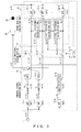
FIG. 2 is a configuration of the active silencer according to the first embodiment of the present invention.
As illustrated inFIG. 2 , the active silencer according to the first embodiment is configured by asensor microphone 11, a controlsignal generation unit 15, a controllingspeaker 24, an actuationsignal determination unit 18, anerror microphone 25, and a soundquality evaluation unit 23. - The
sensor microphone 11 detects a reference signal corresponding to noise.
The controlsignal generation unit 15 is provided with: a band division unit configured by eight band pass filters (hereinafter referred to as a BPF), that is, BPFs 12-1, 12-2, ..., and 12-8, for dividing a signal corresponding to the noise detected by thesensor microphone 11 into eight predetermined bands; an adaptive filter unit configured by eight adaptive filters, that is, adaptive filters 13-1, 13-2, ..., and 13-8, for filtering each of the divided bands; and anadder 14 for adding up the output of the respective adaptive filters. - The
error microphone 25 detects remaining noise remaining after the control sound emitted by the controllingspeaker 24 interferes with noise.
The soundquality evaluation unit 23 is provided with: a band division unit configured by eight band pass filters, that is, BPFs 22-1, 22-2, ..., and 22-8, for dividing a remaining noise signal detected by theerror microphone 25 into eight predetermined bands; and an inter-adjacent-band level difference calculation unit (of a remaining noise signal) configured by a level difference calculation unit 21-1 for calculating a level difference between output of the BPF 22-1 and output of the BPF 22-2; a level difference calculation unit 21-2 for calculating a level difference between output of the BPF 22-2 and output of the BPF 22-3; ...; and a level difference calculation unit 21-7 for calculating a level difference between output of the BPF 22-7 and output of the BPF 22-8. - It is obvious that the bands passed by the BPFs 12-1, 12-2, ..., and 12-8 match the bands passed respectively by the BPFs 22-1, 22-2, ..., and 22-8.
- The actuation
signal determination unit 18 is provided with: a band division unit configured by the above-mentioned BPFs 22-1, 22-2, ..., and 22-8; and a switch unit having a plurality of switches 16-1, 16-2, ..., and 16-8 for comparing the calculated sound pressure level difference between the bands with a corresponding threshold in a plurality of thresholds TH1 through TH7 stored in a threshold storage unit 17, and determining whether or not the output of the BPFs 22-1, 22-2, ..., and 22-8 is to be transmitted to the adaptive filters 13-1, 13-2, ..., and 13-8 at the current time. - Then, the operation of the active silencer according to the first embodiment is described below with reference to the configuration in
FIG. 2 and the flowchart inFIG. 3 .
The active silencer inFIG. 2 performs in parallel the operation by the controlsignal generation unit 15 for processing a reference signal corresponding to the noise detected by thesensor microphone 11 and the operation of the soundquality evaluation unit 23 and the actuationsignal determination unit 18 for processing the remaining noise signal detected by theerror microphone 25. However, in the adaptive filters 13-1, 13-2, ..., and 13-8, when the filter coefficients h1 →(t), h2 →(t), ..., h8 →(t) are updated, the frequency components corresponding to the reference signal and the remaining noise signal detected at the same time are used in an arithmetic operation. - The above-mentioned process is illustrated in the flowchart in
FIG. 3 by the meeting in step S9 of the flow of steps S1 → S3 → S5 → S9 and the flow of steps S2 → S4 → S6 S8 → S9. - In step S1 in
FIG. 3 , thesensor microphone 11 detects a reference signal x(t). In step S3, the detected reference signal x(t) is input to the band pass filters (BPF) 12-1, 12-2, ..., and 12-8, and the band is divided into eight sections. Then, as a result of the division, an update signal x1(t) (i = 1, 2, ..., 8) is obtained by each BPF by the following equation (3), and output to the adaptive filters 13-1, 13-2, ..., and 13-8 at the subsequent stage.
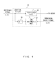
FIG. 4 illustrates the detailed configuration of each adaptive filter illustrated inFIG. 2 . - As illustrated in
FIG. 4 , anadaptive filter 29 is configured by an LMSarithmetic unit 27 for performing an arithmetic operation on the basis of the LMS algorithm, aFIR filter 26 provided at the stage preceding the LMSarithmetic unit 27 and having a fixed filter coefficient, and aFIR filter 28 for which a variable filter coefficient can be set. - The number of taps of the FIR filters 26 is Nw, and is assigned by the transfer function w^→ = [w^(1), w^(2), ..., w^(Nw)] of the error path from the controlling
speaker 24 to theerror microphone 25. In addition, theFIR filter 26 holds xi →(t) = [xi(t), xi(t-1), ..., xi(t-Nw+1)] obtained by sampling Nw reference signals xi (t) at the current time and each time point in the past, and outputs the convolution signal (filter reference signal) by the following equation (4) to the LMS arithmetic unit 27
(* indicates a convolution arithmetic.) - The number of taps of the LMS
arithmetic unit 27 is Nh, and the unit holds ri →(t) = [ri(t), ri(t-1), ..., ri(t-Nh+1)] obtained by sampling Nh filter reference signals at the current time and each time point in the past, obtains the filter coefficient hi →(t+1) = [hi(1, t+1), hi(2, t+1), ..., hi(Nh, t+1)] at the next time point (t + 1) from the filter coefficient hi →(t) = [hi(1, t), hi(2, t), ..., hi(Nh, t)] at tie time t by the following equation (5), and outputs the result to theFIR filter 28.
where ei(t) indicates the i-th frequency component of the band-divided remaining noise signal detected by theerror microphone 106 at the time t, and µ indicates a step size parameter. - The number of taps of the
FIR filter 28 is Nh, and the filter holds xi →(t) = [xi(t), xi(t-1), ..., xi(t-Nh+1) obtained by sampling Nh reference signals xi(t) at the current time and each time point in the past, multiplies the xi →(t) by the filter coefficient hi →(t) = [hi(1, t), hi(2, t), ..., hi(Nh, t)] at the current time, and outputs a result of the multiplication to theadder 14 illustrated inFIG. 2 . - Upon receipt of the output of each adaptive filter, the
adder 14 obtains a sum by the following equation (6), and outputs the sum as a control signal to the controllingspeaker 24. -

Back toFIG. 3 , a control signal is generated in step S5 after step S3 by the adaptive filters 13-1, 13-2, ..., and 13-8 and theadder 14 as described with reference toFIG. 4 above, and output to the controllingspeaker 24. The controllingspeaker 24 generates control sound on the basis of the control signal. Then, control is passed to step S9. - As another flow illustrated in
FIG. 3 , the remaining noise signal e (t) is detected by theerror microphone 25 in step S2.
In step S4, the detected remaining noise signal e(t) is input to the band pass filters (BPF) 22-1, 22-2, ..., and 22-8, and the band is divided into eight sections. Then, the signal ei(t) (i = 1, 2, ..., 8) as a result of the division is obtained by each BPF by the following equation (7), and output to the level difference calculation units 21-1, 21-2, ..., and 21-7 and the switches 16-1, 16-2, ..., and 16-8 at the subsequent stages.
FIG. 5 illustrates the detailed configuration of each level difference calculation unit illustrated inFIG. 2 . - In
FIG. 5 , a leveldifference calculation unit 30 averages and calculates the level differences of the frequency components ei(t) and ei+1(t) (i = 1, ..., 7) between two adjacent bands obtained by band-dividing the remaining noise signal e (t) for the period Te hours back from the current time up to now. - A
multiplexer 31 calculates the square of ei (t) ({e i(t)}2) from ei(t). Delay units 33-1, 33-2, ..., and 33-Te respectively latch the value at the current time and at each time in the past, that is, {ei(t)}2, {ei(t-1) }2, ..., {ei(t-Te)}2. An adder 35-1 adds {ei(t)}2 and ei(t-1))2, ..., an adder 35-(Te-1) adds a result of the addition of an adder 35-(Te-2) to {ei(t-Te+1)}2, and an adder 35-Te adds a result of the addition of the adder 35-(Te-1) to {ei(t-Te)}2e. - A
multiplexer 32 calculates the square of ei+1(t) ({ei+1(t) }2) from ei+1(t). Delay units 34-1, 34-2, ..., and 34-Te respectively latch the value at the current time and at each time in the past, that is, {ei+1(t)}2, {ei+1(t-1) }2, ..., {ei+1(t-Te) }2. An adder 36-1 adds {ei+1(t)}2 and {ei+1(t-1) }2, ..., an adder 36-(Te-1) adds a result of the addition of an adder 36-(Te-2) to {ei+1(t-Te+1) }2, and an adder 36-Te adds a result of the addition of the adder 36-(Te-1) to {ei+1(t-Te)}2. - An
adder 37 subtracts the output of the adder 36-Te from the output of the adder 35-Te. The output of theadder 37 is assigned by the following equation (8). -

In step S6 after step S4 back inFIG. 3 , the (sound pressure) level difference between the adjacent bands of the remaining noise signal is calculated as described above with reference toFIG. 5 . - In step S8, it is determined whether or not the frequency component is to be passed through each of the bands of the remaining noise signal depending on whether or not the switches 16-1, 16-2, ..., and 16-8 are to be conducting.
-
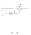
FIG. 6A illustrates the detailed configuration of any of the switches 16-2, ..., and 16-7 inFIG. 2 .
InFIG. 6A , aswitch 41 determines whether or not the remaining noise signal ei(t) (i = 2, ..., 7) is to be conducting depending on the output of an ORarithmetic unit 44. - A
determination unit 42 determines whether or not -di(t) obtained by inverting the sign of the sound pressure level difference di(t) is larger than the threshold THi, and adetermination unit 43 determines whether or not the sound pressure level difference di-1(t) is larger than the threshold THi-1. - The OR
arithmetic unit 44 outputs a signal for disabling theswitch 41 to be conducting when thedetermination unit 42 issues a signal indicating that -di(t) is larger than the threshold TH1, or thedetermination unit 43 issues a signal indicating that -di-1(t) is larger than the threshold THi-1. -
FIG. 6B illustrates the detailed configuration of the switch 16-1 illustrated inFIG. 2 .
InFIG. 6B , aswitch 46 determines whether or not the remaining noise signal e1(t) is to be conducting depending on the output of adetermination unit 47. - The
determination unit 47 determines whether or not -d1(t) obtained by inverting the sign of the sound pressure level difference d1(t) is larger than the threshold TH1. If it is determined that -d1(t) is larger than the threshold TH1, it outputs a signal for disabling theswitch 46 to be conducting. -
FIG. 6C illustrates the detailed configuration of the switch 16-8 illustrated inFIG. 2 .
InFIG. 6C , aswitch 48 determines whether or not the remaining noise signal e8(t) depending on the output of adetermination unit 49. - The
determination unit 49 determines whether or not the sound pressure level difference d7(t) is larger than the threshold TH8. If it is determined that d7(t) is larger than the threshold TH7, the unit outputs a signal for disabling theswitch 48 to be conducting. - Thus, in step S8 illustrated in
FIG. 3 , it is determined whether or not a frequency component is to be passed through each band of a remaining noise signal by the following equations (9) through (11).
(where i = 2, ..., 7)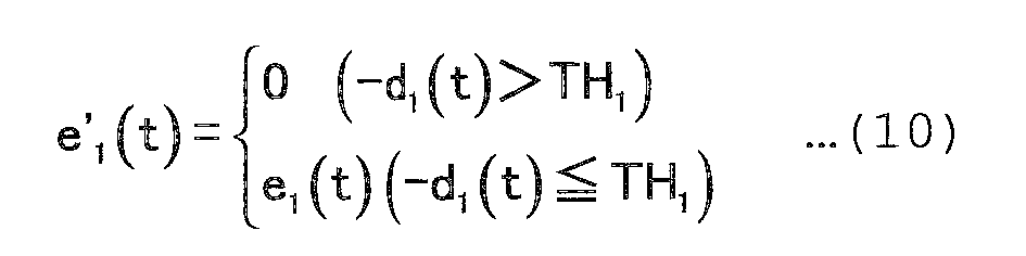

In step S9 illustrated inFIG. 3 , the filter coefficient hi+1 →(t) of each adaptive filter at the next time point (t + 1) is obtained by the equation (5) described above with reference toFIG. 4 on the basis of the frequency component xi(t) of each band of the reference signal x(t), e'i(t) obtained from the frequency component ei(t) of each band of the remaining noise signal e(t), and the filter coefficient hi →(t) of each adaptive filter at the current time t. -
FIG. 7 illustrates the sound pressure level of each band at the initial stage, and the sound pressure level of each band after the activation of the active silencer according to the present invention.
FIG. 7 illustrates, for example, the sound pressure level of the bands passed through by the BPFs 22-1, 22-2, ..., and 22-8 in order from the rightmost. In this example, the sound pressure level of the band passed through by the BPF 22-5 is outstanding, and the band corresponds to the non-silenced band. - The sound pressure level of each frequency band of the remaining noise is initially flat, and after some time has passed with the active silencer according to the first embodiment operated, the occurs differences in silencing performance among the bands.
However, in the first embodiment, the actuationsignal determination unit 18 determines whether or not the frequency component ei(t) (i = 1, ..., 8) detected at the current time t is to be passed through the i-th adaptive filter 13-i for each frequency band of remaining noise. - As illustrated in
FIGS. 6A through 6C , if the frequency component of the current band is excessively erased (exceeding the threshold) as compared with an adjacent lower frequency band, or excessively erased (exceeding the threshold) as compared with an adjacent higher frequency band for the current band during the determination, then the frequency component detected at the current time is prevented from being output to the adaptive filter on the current band. - In this case, the filter coefficient of the adaptive filter corresponding to the current band is not updated from the time point when the threshold is exceeded, and the frequency component of the current band is no more erased according to the remaining noise signal. Therefore, each band can be silenced while preventing the development of the difference between the sound pressure level of the remaining noise of the current band and the sound pressure level of the band of one of the adjacent bands or the sound pressure levels of both of the adjacent bands, thereby protecting the non-silenced band from sounding noisy.
- In
FIG. 7 , a non-silenced band is included in the bands to be passed through one BPF. However, even when a non-silenced band spans a plurality of bands to be passed through a plurality of BPFs, the method by the equations (9) through (11) according to the first embodiment is effective. - Described below is the second embodiment.
The configurations of the devices are different in the spectrum continuity evaluating portion of remaining noise between the first and second embodiments. - In the first embodiment, remaining noise is divided into a plurality of bands using a plurality of band pass filters, and the sound pressure level difference between adjacent bands are calculated. On the other hand, in the second embodiment, the frequency of remaining noise is analyzed, and the sound pressure level difference between the bands is calculated using the power spectrum calculated on the basis of the result of the frequency analysis.
-
FIG. 8 is a configuration of the active silencer according to the second embodiment of the present invention.
InFIG. 8 , the components are the same as those illustrated inFIG. 2 except a soundquality evaluation unit 54, and the descriptions of these components are omitted here.
The soundquality evaluation unit 54 includes a fast Fourier transform processing unit (FFT processing unit) 51, a powerspectrum calculation unit 52, and an inter-band leveldifference calculation unit 53. - The fast Fourier
transform processing unit 51 analyzes the frequency of the remaining noise signal e (t) from theerror microphone 25.
The powerspectrum calculation unit 52 calculates the power spectrum on the basis of the result obtained by the frequency analysis. - The inter-band level
difference calculation unit 53 calculates the difference of the sound pressure level between the adjacent bands in a plurality of bands passed by a plurality of BPSs provided in the actuationsignal determination unit 18 on the basis of the calculated power spectrum. - The calculated level differences d1(t) to d7(t) between the adjacent bands are output to the actuation
signal determination unit 18. The subsequent operations are the same as those according to the first embodiment.
Described next is the third embodiment. -
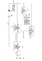
FIG. 9 is a configuration of the active silencer according to the third embodiment of the present invention.
InFIG. 9 , athreshold change unit 57 for dynamically changing a threshold for determination of the continuous spectrum of remaining noise is added to the configuration illustrated inFIG. 2 . -
FIG. 10 illustrates the detailed configuration of the threshold change unit inFIG. 9 .
InFIG. 10 , thethreshold change unit 57 is configured by BPF 61-1, ..., and BPF 61-8, level calculation units 62-1, ..., and level difference calculation unit 62-8, a maximalband determination unit 64, and athreshold estimate unit 63. - The BPF 61-1, ..., and BPF 61-8 divide the remaining noise signal e (t) from the
error microphone 25 into eight bands corresponding to the eight BPFs of the actuation signal determination unit 56. - The level calculation units 62-1, ..., and level difference calculation unit 62-8 respectively input the band components e1(t), ..., e8(t) of the remaining noise signal, and calculate the average value of the band components for Te hours , thereby obtaining the average value of the sound pressure level of each band.
- A level calculation unit 62i for processing the i-th (i = 1, ..., 8) band component ei (t) performs, for example, the following operation.
The square of ei(t) ({ei(t)}2) is calculated from the input ei(t). In addition, by obtaining the sum of the values at the respective time points at the current time and in the past, that is, {ei(t)}2, {ei(t-1)}2, ..., {ei(t-Te)}2 latched in a plurality of delay units (not illustrated in the attached drawings), the output Bli of the level calculation unit 62-i can be obtained by the following equation (12). -

The maximalband determination unit 64 inputs the output b11, ..., b18 of the level calculation units 62-1, ..., and level difference calculation unit 62-8 as the sound pressure levels of the respective bands, compares the sound pressure levels of the respective bands, determines a band (maximal band) having a higher sound pressure level than the surrounding bands, and outputs the inter-band numbers b1, b2, ... indicating both ends of the band determined as the maximal band to thethreshold estimate unit 63. - The
threshold estimate unit 63 changes the values of the thresholds THb1, THb2, ... corresponding to the inter-band numbers b1, b2, ... from the maximalband determination unit 64, and outputs the resultant values to the threshold storage unit 17 in the actuationsignal determination unit 18 illustrated inFIG. 9 . - Described next is two methods of changing the threshold of a specified inter-band number by the
threshold estimate unit 63.
In the first method, a threshold is changed as follows. - 1. Independent of a threshold among bands, a second threshold is assigned for determination as to whether or not a sound pressure level of each band is high.
- 2. When the sound pressure level of the maximal band of remaining noise is higher than the second threshold, a smaller value is set as a threshold among the bands (thus, when remaining noise tends to sound noisy, the update of a filter coefficient can be controlled for each divided band not to cause a discontinuous spectrum).
- 3. When the sound pressure level of the maximal band of remaining noise is equal to or lower than the second threshold, a larger value is set as a threshold among the bands (thus, when remaining noise tends to sound noisy, the update of a filter coefficient can be controlled for each divided band to improve the silencing performance).
- By performing the above-mentioned control, the silencing performance can be enhanced without generating noisy sound (unusual sound) even when a hardly-silenced ban is changed by the ambient noise or the surrounding environment of the active silencer in the first method.
- A threshold is changed as follows in the second method.
When the maximal band of remaining noise belongs to a high sensitive band for human ears, the threshold for the band is set as a smaller value. With the configuration, control can be performed to improve the silencing performance while suppressing the generation of noisy sound (unusual sound).
Claims (9)
- An active silencer comprising:a speaker to generate control sound which interferes with noise;a microphone to detect noise remaining after the interference as a remaining noise signal;a sound quality evaluation unit to evaluate sound quality of the remaining noise and output a result of the sound quality evaluation;an actuation signal determination unit to determine, according to the result of the sound quality evaluation, detection timing of a frequency component of a remaining noise signal to be used when the control sound is generated for a plurality of bands of the remaining noise, corresponding to the plurality of bands of a reference signal corresponding to the noise; anda control signal generation unit to generate and output a control signal for generation of the control sound depending on a plurality of bands of the determined remaining noise signal and a plurality of bands of the reference signal corresponding to the noise.
- The active silencer according to claim 1, wherein:the actuation signal determination unit comprises:a first band division unit to divide the remaining noise signal into a plurality of frequency bands; anda switch unit having a plurality of switches for determining whether or not the frequency component of each band of the remaining noise signal detected at the current time is to be passed through the control signal generation unit depending on the result of the sound quality evaluation; andthe control signal generation unit comprises:a second band division unit to divide the reference signal into a plurality of bands corresponding to a plurality of bands of the remaining noise;an adaptive filter unit provided with a plurality of adaptive filters having a variable filter coefficient for filtering the frequency component of the reference signal detected at the current time and generating a second control signal for each corresponding band of the remaining noise signal and the reference signal so that the frequency component which has passed through the switch can be reduced; andan adder to obtain a sum of the second control signal, generating the control signal, and outputting the signal to the speaker.
- The active silencer according to claim 2, wherein:the sound quality evaluation unit calculates the difference in the sound pressure levels between the adjacent bands of the remaining noise signal;the actuation signal determination unit controls the switch not to pass the frequency component of the remaining noise signal of the current band when the sound pressure level of the current band is equal to or smaller than a predetermined value than the sound pressure level of a lower adjacent band, or when the sound pressure level of the current band is equal to or smaller than a predetermined value than the sound pressure level of a higher adjacent band.
- The active silencer according to claim 3, wherein
the sound quality evaluation unit analyzes a frequency of the remaining noise signal, and calculates a difference in sound pressure level between adjacent bands of the remaining noise signal divided by the first band division unit. - The active silencer according to claim 3 or 4, further comprising
a threshold change unit to change the threshold depending on a sound pressure level for each band of the remaining noise signal. - The active silencer according to claim 5, wherein
the threshold change unit changes the threshold to be used in determining a band into a smaller value if the sound pressure level of the band is equal to or larger than a predetermined value when the sound pressure level of the remaining noise is outstanding in the band, and
changes the threshold to be used in determining a band into a larger value if the sound pressure level of the band is smaller than the predetermined value when the sound pressure level of the remaining noise is outstanding in the band. - The active silencer according to claim 5, wherein
the threshold change unit changes the threshold to be used in determining a band into a smaller value when the band having an outstanding sound pressure level of the remaining noise refers to high sensitivity to human ears. - A method for controlling an active silencer comprising:a step of detecting noise remaining after interfering with control sound as a remaining noise signal;a step of evaluating sound quality of the remaining noise and outputting a result of the sound quality evaluation;an actuation signal determining step of determining, according to the result of the sound quality evaluation, detection timing of a frequency component of a remaining noise signal to be used when the control sound is generated for a plurality of bands of the remaining noise, corresponding to the plurality of bands of a reference signal corresponding to the noise; anda control signal generating step of generating and outputting a control signal for generation of the control sound depending on a plurality of bands of the determined remaining noise signal and a plurality of bands of the reference signal corresponding to the noise.
- The method for controlling the active silencer according to claim 8, wherein
in the actuation signal determining step, for each band of a remaining noise signal detected at a current time point, it is determined as to whether or not the frequency component is to be passed through for use in generating the control sound by switching a plurality of switches depending on the result of the sound quality evaluation
Applications Claiming Priority (1)
| Application Number | Priority Date | Filing Date | Title |
|---|---|---|---|
| PCT/JP2007/001033 WO2009037733A1 (en) | 2007-09-21 | 2007-09-21 | Active silencer and method of controlling active silencer |
Publications (2)
| Publication Number | Publication Date |
|---|---|
| EP2189975A1 true EP2189975A1 (en) | 2010-05-26 |
| EP2189975A4 EP2189975A4 (en) | 2015-04-15 |
Family
ID=40467566
Family Applications (1)
| Application Number | Title | Priority Date | Filing Date |
|---|---|---|---|
| EP07827812.4A Withdrawn EP2189975A4 (en) | 2007-09-21 | 2007-09-21 | ACTIVE SILENT AND METHOD FOR CONTROLLING ACTIVE SILENT |
Country Status (5)
| Country | Link |
|---|---|
| US (1) | US8189800B2 (en) |
| EP (1) | EP2189975A4 (en) |
| JP (1) | JP4973733B2 (en) |
| CN (1) | CN101802905B (en) |
| WO (1) | WO2009037733A1 (en) |
Cited By (2)
| Publication number | Priority date | Publication date | Assignee | Title |
|---|---|---|---|---|
| IT201900005116A1 (en) * | 2019-04-04 | 2020-10-04 | Lavorosostenibile Srl | ACTIVE ATTENUATION AND NOISE CONTROL DEVICE |
| CN113390655A (en) * | 2021-06-09 | 2021-09-14 | 中车株洲电力机车有限公司 | Active noise reduction effect evaluation method suitable for urban rail vehicle |
Families Citing this family (22)
| Publication number | Priority date | Publication date | Assignee | Title |
|---|---|---|---|---|
| JP2012023637A (en) * | 2010-07-15 | 2012-02-02 | Audio Technica Corp | Noise cancel headphone |
| JP5670291B2 (en) * | 2011-11-10 | 2015-02-18 | 本田技研工業株式会社 | Active vibration noise control device |
| EP2814026A4 (en) * | 2012-02-08 | 2016-03-02 | Kyushu Inst Technology | DEVICE FOR MOMING |
| DE102012212843A1 (en) * | 2012-07-23 | 2014-01-23 | Behr Gmbh & Co. Kg | air conditioning |
| US10531190B2 (en) * | 2013-03-15 | 2020-01-07 | Elwha Llc | Portable electronic device directed audio system and method |
| US10575093B2 (en) | 2013-03-15 | 2020-02-25 | Elwha Llc | Portable electronic device directed audio emitter arrangement system and method |
| US10291983B2 (en) | 2013-03-15 | 2019-05-14 | Elwha Llc | Portable electronic device directed audio system and method |
| US9886941B2 (en) | 2013-03-15 | 2018-02-06 | Elwha Llc | Portable electronic device directed audio targeted user system and method |
| US10181314B2 (en) | 2013-03-15 | 2019-01-15 | Elwha Llc | Portable electronic device directed audio targeted multiple user system and method |
| CN104244123B (en) * | 2013-06-21 | 2019-01-01 | Akg声学有限公司 | Earphone and method for active noise suppression |
| US9191050B1 (en) * | 2014-08-21 | 2015-11-17 | Qualcomm Incorporated | Multi-layer coefficient control for dynamic interference cancellation |
| CN105278452B (en) * | 2015-10-16 | 2018-06-26 | 厦门金鹭特种合金有限公司 | A kind of active noise-reduction method of numerical control machining center for metal cutting |
| JP6671036B2 (en) * | 2016-07-05 | 2020-03-25 | パナソニックIpマネジメント株式会社 | Noise reduction device, mobile device, and noise reduction method |
| CN106251856B (en) * | 2016-07-26 | 2021-03-09 | Tcl通讯科技(成都)有限公司 | Environmental noise elimination system and method based on mobile terminal |
| US10037755B2 (en) * | 2016-11-25 | 2018-07-31 | Signal Processing, Inc. | Method and system for active noise reduction |
| KR101902122B1 (en) * | 2017-06-29 | 2018-11-08 | 순천대학교 산학협력단 | Active noise reduction method and system for improving audibility on residual noise |
| WO2019152241A1 (en) * | 2018-02-02 | 2019-08-08 | Gentherm Inc. | Active noise cancellation system for reducing noise generated by climate control system |
| CN116052629B (en) * | 2023-01-04 | 2025-08-08 | 东风柳州汽车有限公司 | Active noise control method, device, equipment and storage medium |
| CN116704997A (en) * | 2023-07-12 | 2023-09-05 | 广东电网有限责任公司广州供电局 | There are sound tuning cancellation method, device, electronic device and noise cancellation system |
| US20250225974A1 (en) * | 2024-01-05 | 2025-07-10 | Bose Corporation | Systems and methods for adjusting harmonic cancellation |
| CN118748003B (en) * | 2024-08-08 | 2025-12-02 | 宁波方太厨具有限公司 | Active noise cancellation system and its control method, abnormal noise detection method and device |
| CN119832888B (en) * | 2024-12-30 | 2025-11-11 | 北京绿创声学工程股份有限公司 | Active vibration isolation method based on noise reduction technology |
Family Cites Families (25)
| Publication number | Priority date | Publication date | Assignee | Title |
|---|---|---|---|---|
| JP2845476B2 (en) * | 1989-02-16 | 1999-01-13 | 株式会社東芝 | Noise canceller |
| US5293578A (en) | 1989-07-19 | 1994-03-08 | Fujitso Ten Limited | Noise reducing device |
| JPH0727391B2 (en) * | 1989-07-19 | 1995-03-29 | 富士通テン株式会社 | Noise reduction device |
| JP2517150B2 (en) | 1990-03-30 | 1996-07-24 | 松下電器産業株式会社 | Silencer |
| JPH05218805A (en) * | 1992-01-31 | 1993-08-27 | Sony Corp | Adaptive processor |
| US5410606A (en) * | 1992-07-21 | 1995-04-25 | Honda Giken Kogyo Kabushiki Kaisha | Noise canceling method |
| CA2125220C (en) | 1993-06-08 | 2000-08-15 | Joji Kane | Noise suppressing apparatus capable of preventing deterioration in high frequency signal characteristic after noise suppression and in balanced signal transmitting system |
| JP2993626B2 (en) * | 1993-06-08 | 1999-12-20 | 松下電器産業株式会社 | Noise suppression device |
| JP2872545B2 (en) | 1993-09-14 | 1999-03-17 | 松下電器産業株式会社 | Silencer |
| JP3617079B2 (en) | 1994-08-29 | 2005-02-02 | 日産自動車株式会社 | Active noise control device and active vibration control device |
| US5991418A (en) | 1996-12-17 | 1999-11-23 | Texas Instruments Incorporated | Off-line path modeling circuitry and method for off-line feedback path modeling and off-line secondary path modeling |
| US6198828B1 (en) | 1996-12-17 | 2001-03-06 | Texas Instruments Incorporated | Off-line feedback path modeling circuitry and method for off-line feedback path modeling |
| JPH10191497A (en) | 1996-12-17 | 1998-07-21 | Texas Instr Inc <Ti> | Digital hearing aid, and modeling method for feedback path |
| US6418227B1 (en) | 1996-12-17 | 2002-07-09 | Texas Instruments Incorporated | Active noise control system and method for on-line feedback path modeling |
| JPH10190589A (en) * | 1996-12-17 | 1998-07-21 | Texas Instr Inc <Ti> | Adaptive noise control system and on-line feedback route modeling and on-line secondary route modeling method |
| JPH11259078A (en) * | 1998-03-16 | 1999-09-24 | Oki Electric Ind Co Ltd | Active noise control device |
| JP3675179B2 (en) * | 1998-07-17 | 2005-07-27 | 三菱電機株式会社 | Audio signal denoising device |
| JP3837685B2 (en) * | 1998-10-07 | 2006-10-25 | 富士通株式会社 | Active noise control method and receiver |
| JP4145507B2 (en) * | 2001-06-07 | 2008-09-03 | 松下電器産業株式会社 | Sound quality volume control device |
| JP3800147B2 (en) * | 2002-08-07 | 2006-07-26 | ソニー株式会社 | Adaptive noise reduction method for camera-integrated recording apparatus |
| CN1538718A (en) * | 2003-04-18 | 2004-10-20 | 摩托罗拉公司 | Method and system for active voice cancellation |
| JP4218573B2 (en) | 2004-04-12 | 2009-02-04 | ソニー株式会社 | Noise reduction method and apparatus |
| JP4790843B2 (en) * | 2007-03-30 | 2011-10-12 | 富士通株式会社 | Active silencer and active silencer method |
| JP5707663B2 (en) * | 2008-04-18 | 2015-04-30 | 富士通株式会社 | Active silencer |
| JP2010249939A (en) * | 2009-04-13 | 2010-11-04 | Sony Corp | Noise reduction device and noise determination method |
-
2007
- 2007-09-21 CN CN2007801006427A patent/CN101802905B/en not_active Expired - Fee Related
- 2007-09-21 EP EP07827812.4A patent/EP2189975A4/en not_active Withdrawn
- 2007-09-21 JP JP2009532969A patent/JP4973733B2/en not_active Expired - Fee Related
- 2007-09-21 WO PCT/JP2007/001033 patent/WO2009037733A1/en not_active Ceased
-
2010
- 2010-03-15 US US12/724,237 patent/US8189800B2/en not_active Expired - Fee Related
Cited By (3)
| Publication number | Priority date | Publication date | Assignee | Title |
|---|---|---|---|---|
| IT201900005116A1 (en) * | 2019-04-04 | 2020-10-04 | Lavorosostenibile Srl | ACTIVE ATTENUATION AND NOISE CONTROL DEVICE |
| CN113390655A (en) * | 2021-06-09 | 2021-09-14 | 中车株洲电力机车有限公司 | Active noise reduction effect evaluation method suitable for urban rail vehicle |
| CN113390655B (en) * | 2021-06-09 | 2022-04-08 | 中车株洲电力机车有限公司 | Active noise reduction effect evaluation method suitable for urban rail vehicle |
Also Published As
| Publication number | Publication date |
|---|---|
| CN101802905A (en) | 2010-08-11 |
| EP2189975A4 (en) | 2015-04-15 |
| JP4973733B2 (en) | 2012-07-11 |
| US20100172511A1 (en) | 2010-07-08 |
| JPWO2009037733A1 (en) | 2010-12-24 |
| US8189800B2 (en) | 2012-05-29 |
| CN101802905B (en) | 2012-09-26 |
| WO2009037733A1 (en) | 2009-03-26 |
Similar Documents
| Publication | Publication Date | Title |
|---|---|---|
| EP2189975A1 (en) | Active silencer and method of controlling active silencer | |
| US8199924B2 (en) | System for active noise control with an infinite impulse response filter | |
| KR101798120B1 (en) | Apparatus and method for improving the perceived quality of sound reproduction by combining active noise cancellation and perceptual noise compensation | |
| JP4790843B2 (en) | Active silencer and active silencer method | |
| JP5707663B2 (en) | Active silencer | |
| KR101149591B1 (en) | Audio signal dereverberation | |
| JPH08509823A (en) | Single and multi-channel block adaptation method and apparatus for active acoustic and vibration control | |
| JP2009290825A (en) | Acoustic echo canceler | |
| EP4094252B1 (en) | Systems and methods for detecting noise floor of a sensor | |
| JP4860712B2 (en) | Hearing aid with adaptive feedback suppression | |
| JP5292931B2 (en) | Acoustic echo canceller and echo cancellation device | |
| JP6116300B2 (en) | Active silencer system | |
| EP3948845B1 (en) | Systems and methods for detecting divergence in an adaptive system | |
| JP5546795B2 (en) | Target wave reduction device | |
| JP4690243B2 (en) | Digital filter, periodic noise reduction device, and noise reduction device | |
| JP2002311960A (en) | Passive noise eliminating device | |
| JP2011070084A (en) | Sound/soundless determination device, sound/soundless determination method, and sound/soundless determination program | |
| JPH09146588A (en) | Emergency vehicle alarm sound detector | |
| JP2009207021A (en) | Acoustic echo canceler | |
| JP2010276773A5 (en) | ||
| JP5646806B2 (en) | Active noise control device and active noise control method | |
| JPH10187201A (en) | Adaptive type active silencer | |
| JP4004708B2 (en) | Active silencer | |
| JPH0869291A (en) | Muffler | |
| JP4516774B2 (en) | Vibration control system |
Legal Events
| Date | Code | Title | Description |
|---|---|---|---|
| PUAI | Public reference made under article 153(3) epc to a published international application that has entered the european phase |
Free format text: ORIGINAL CODE: 0009012 |
|
| 17P | Request for examination filed |
Effective date: 20100412 |
|
| AK | Designated contracting states |
Kind code of ref document: A1 Designated state(s): AT BE BG CH CY CZ DE DK EE ES FI FR GB GR HU IE IS IT LI LT LU LV MC MT NL PL PT RO SE SI SK TR |
|
| AX | Request for extension of the european patent |
Extension state: AL BA HR MK RS |
|
| DAX | Request for extension of the european patent (deleted) | ||
| RA4 | Supplementary search report drawn up and despatched (corrected) |
Effective date: 20150313 |
|
| RIC1 | Information provided on ipc code assigned before grant |
Ipc: G10K 11/178 20060101AFI20150309BHEP Ipc: G10L 21/0232 20130101ALI20150309BHEP Ipc: G10L 21/0208 20130101ALI20150309BHEP Ipc: F01N 1/06 20060101ALI20150309BHEP |
|
| STAA | Information on the status of an ep patent application or granted ep patent |
Free format text: STATUS: THE APPLICATION HAS BEEN WITHDRAWN |
|
| 18W | Application withdrawn |
Effective date: 20180208 |
|
| RIC1 | Information provided on ipc code assigned before grant |
Ipc: G10K 11/178 20060101AFI20150309BHEP Ipc: G10L 21/0208 20130101ALI20150309BHEP Ipc: G10L 21/0232 20130101ALI20150309BHEP Ipc: F01N 1/06 20060101ALI20150309BHEP |
|
| RIC1 | Information provided on ipc code assigned before grant |
Ipc: G10K 11/178 20060101AFI20150309BHEP Ipc: G10L 21/0232 20130101ALI20150309BHEP Ipc: G10L 21/0208 20130101ALI20150309BHEP Ipc: F01N 1/06 20060101ALI20150309BHEP |