EP2189648B1 - Armature arrangement - Google Patents
Armature arrangement Download PDFInfo
- Publication number
- EP2189648B1 EP2189648B1 EP08169457A EP08169457A EP2189648B1 EP 2189648 B1 EP2189648 B1 EP 2189648B1 EP 08169457 A EP08169457 A EP 08169457A EP 08169457 A EP08169457 A EP 08169457A EP 2189648 B1 EP2189648 B1 EP 2189648B1
- Authority
- EP
- European Patent Office
- Prior art keywords
- armature
- cavity
- vent holes
- valve body
- slots
- Prior art date
- Legal status (The legal status is an assumption and is not a legal conclusion. Google has not performed a legal analysis and makes no representation as to the accuracy of the status listed.)
- Active
Links
- 239000000446 fuel Substances 0.000 claims abstract description 49
- 239000012530 fluid Substances 0.000 claims abstract description 32
- 230000015572 biosynthetic process Effects 0.000 claims abstract description 16
- 238000002347 injection Methods 0.000 claims abstract description 14
- 239000007924 injection Substances 0.000 claims abstract description 14
- 238000003754 machining Methods 0.000 claims description 7
- 238000004519 manufacturing process Methods 0.000 claims description 7
- 230000000694 effects Effects 0.000 abstract description 3
- 238000005755 formation reaction Methods 0.000 description 10
- 230000008901 benefit Effects 0.000 description 6
- 238000004891 communication Methods 0.000 description 5
- 238000002485 combustion reaction Methods 0.000 description 3
- 230000004907 flux Effects 0.000 description 3
- 238000013022 venting Methods 0.000 description 3
- 230000003749 cleanliness Effects 0.000 description 2
- 238000013016 damping Methods 0.000 description 2
- 239000006260 foam Substances 0.000 description 2
- 239000000203 mixture Substances 0.000 description 2
- 230000003068 static effect Effects 0.000 description 2
- 238000005452 bending Methods 0.000 description 1
- 230000009286 beneficial effect Effects 0.000 description 1
- 238000005520 cutting process Methods 0.000 description 1
- 229910003460 diamond Inorganic materials 0.000 description 1
- 239000010432 diamond Substances 0.000 description 1
- 238000005553 drilling Methods 0.000 description 1
- 230000003628 erosive effect Effects 0.000 description 1
- 239000007788 liquid Substances 0.000 description 1
- 239000000463 material Substances 0.000 description 1
Images


Classifications
-
- F—MECHANICAL ENGINEERING; LIGHTING; HEATING; WEAPONS; BLASTING
- F02—COMBUSTION ENGINES; HOT-GAS OR COMBUSTION-PRODUCT ENGINE PLANTS
- F02M—SUPPLYING COMBUSTION ENGINES IN GENERAL WITH COMBUSTIBLE MIXTURES OR CONSTITUENTS THEREOF
- F02M63/00—Other fuel-injection apparatus having pertinent characteristics not provided for in groups F02M39/00 - F02M57/00 or F02M67/00; Details, component parts, or accessories of fuel-injection apparatus, not provided for in, or of interest apart from, the apparatus of groups F02M39/00 - F02M61/00 or F02M67/00; Combination of fuel pump with other devices, e.g. lubricating oil pump
- F02M63/0012—Valves
- F02M63/0014—Valves characterised by the valve actuating means
- F02M63/0015—Valves characterised by the valve actuating means electrical, e.g. using solenoid
-
- F—MECHANICAL ENGINEERING; LIGHTING; HEATING; WEAPONS; BLASTING
- F02—COMBUSTION ENGINES; HOT-GAS OR COMBUSTION-PRODUCT ENGINE PLANTS
- F02M—SUPPLYING COMBUSTION ENGINES IN GENERAL WITH COMBUSTIBLE MIXTURES OR CONSTITUENTS THEREOF
- F02M47/00—Fuel-injection apparatus operated cyclically with fuel-injection valves actuated by fluid pressure
- F02M47/02—Fuel-injection apparatus operated cyclically with fuel-injection valves actuated by fluid pressure of accumulator-injector type, i.e. having fuel pressure of accumulator tending to open, and fuel pressure in other chamber tending to close, injection valves and having means for periodically releasing that closing pressure
- F02M47/027—Electrically actuated valves draining the chamber to release the closing pressure
-
- F—MECHANICAL ENGINEERING; LIGHTING; HEATING; WEAPONS; BLASTING
- F02—COMBUSTION ENGINES; HOT-GAS OR COMBUSTION-PRODUCT ENGINE PLANTS
- F02M—SUPPLYING COMBUSTION ENGINES IN GENERAL WITH COMBUSTIBLE MIXTURES OR CONSTITUENTS THEREOF
- F02M51/00—Fuel-injection apparatus characterised by being operated electrically
- F02M51/06—Injectors peculiar thereto with means directly operating the valve needle
- F02M51/061—Injectors peculiar thereto with means directly operating the valve needle using electromagnetic operating means
- F02M51/0625—Injectors peculiar thereto with means directly operating the valve needle using electromagnetic operating means characterised by arrangement of mobile armatures
-
- F—MECHANICAL ENGINEERING; LIGHTING; HEATING; WEAPONS; BLASTING
- F02—COMBUSTION ENGINES; HOT-GAS OR COMBUSTION-PRODUCT ENGINE PLANTS
- F02M—SUPPLYING COMBUSTION ENGINES IN GENERAL WITH COMBUSTIBLE MIXTURES OR CONSTITUENTS THEREOF
- F02M63/00—Other fuel-injection apparatus having pertinent characteristics not provided for in groups F02M39/00 - F02M57/00 or F02M67/00; Details, component parts, or accessories of fuel-injection apparatus, not provided for in, or of interest apart from, the apparatus of groups F02M39/00 - F02M61/00 or F02M67/00; Combination of fuel pump with other devices, e.g. lubricating oil pump
- F02M63/0012—Valves
- F02M63/0031—Valves characterized by the type of valves, e.g. special valve member details, valve seat details, valve housing details
- F02M63/004—Sliding valves, e.g. spool valves, i.e. whereby the closing member has a sliding movement along a seat for opening and closing
-
- F—MECHANICAL ENGINEERING; LIGHTING; HEATING; WEAPONS; BLASTING
- F02—COMBUSTION ENGINES; HOT-GAS OR COMBUSTION-PRODUCT ENGINE PLANTS
- F02M—SUPPLYING COMBUSTION ENGINES IN GENERAL WITH COMBUSTIBLE MIXTURES OR CONSTITUENTS THEREOF
- F02M63/00—Other fuel-injection apparatus having pertinent characteristics not provided for in groups F02M39/00 - F02M57/00 or F02M67/00; Details, component parts, or accessories of fuel-injection apparatus, not provided for in, or of interest apart from, the apparatus of groups F02M39/00 - F02M61/00 or F02M67/00; Combination of fuel pump with other devices, e.g. lubricating oil pump
- F02M63/0012—Valves
- F02M63/007—Details not provided for in, or of interest apart from, the apparatus of the groups F02M63/0014 - F02M63/0059
-
- F—MECHANICAL ENGINEERING; LIGHTING; HEATING; WEAPONS; BLASTING
- F02—COMBUSTION ENGINES; HOT-GAS OR COMBUSTION-PRODUCT ENGINE PLANTS
- F02M—SUPPLYING COMBUSTION ENGINES IN GENERAL WITH COMBUSTIBLE MIXTURES OR CONSTITUENTS THEREOF
- F02M2200/00—Details of fuel-injection apparatus, not otherwise provided for
- F02M2200/04—Fuel-injection apparatus having means for avoiding effect of cavitation, e.g. erosion
Definitions
- the invention relates to an armature arrangement for use in a solenoid fuel injector.
- the invention relates to an armature arrangement for use in a solenoid fuel injector, being arranged to deliver pressurised fuel from a high pressure accumulator to a cylinder of a diesel internal combustion engine.
- EP 0798459 describes a solenoid fuel injector in which a valve needle is moveable along the centre line of a nozzle body and engageable with a valve seat to control the flow of fuel from a high pressure fuel supply line through the nozzle body.
- the end of the valve needle remote from the valve seat extends within a control chamber, the control chamber being arranged to receive fuel from the high pressure fuel supply line through a restrictor.
- the valve needle is biased into engagement with the valve seat by means of the fuel pressure within the control chamber and a spring.
- a control valve is moveable under the influence of a solenoid actuator which is immersed in relatively low pressure fuel.
- the end of the control valve in proximity to the solenoid actuator carries an armature.
- the control valve In use, when the solenoid actuator is energised, the control valve is lifted thereby allowing pressurised fuel from the control chamber to escape to a suitable low pressure drain. As the control chamber communicates with the fuel supply line through the restrictor, the fuel pressure within the control chamber falls sufficiently to permit the valve needle to leave the valve seat against the biasing force of the spring.
- Modern diesel internal combustion engines require fuel injectors of the sort described above to operate under increasing fuel pressures in excess of 1500 bar. Under such pressures, the control valve requires a large force to lift it.
- the magnetic force that the solenoid actuator can generate can be increased by reducing a gap between the solenoid actuator and the armature of the control valve. In operation, the gap contains fuel, a foam of fuel or a fuel vapour and air mixture.
- the armature is required to move at high speeds causing fluid to be expelled from the gap when the control valve lifts and to be sucked back into the gap when the valve closes.
- EP 1 760 308 A describes an armature having a recess in a first surface for receiving a spring, and through-holes that extend through the armature from the first surface to a second, opposite surface. Communication grooves are provided in the first surface that extend radially from the recess to connect with the through-holes. The communication grooves modify the fluid flow around the armature.
- US 5 743 238 describes an armature having a recess for receiving a screw, and through-holes that extend through the armature from a first surface to a second, opposite surface. Channels are provided in the first surface that extend radially from the recess to connect with the through-holes.
- an armature arrangement comprising an armature having one or more vent holes, a valve body associated with the armature which is provided with a cavity.
- An upper surface of the armature is provided with at least one formation to allow enhanced fluid flow from the vent holes to the cavity.
- the at least one formation comprises a plurality of non-radial slots connected to the cavity.
- the cavity is defined by a countersink having a chamfer wherein the countersink is suitable for receiving the valve body.
- mirror symmetry of said formations about a plane along (or through) the valve body axis is also desirable to avoid rotational forces on the armature.
- the armature prefferably be provided with a plurality of vent holes to optimise fluid flow through the armature. Furthermore, it is preferable that the valve body is received within the cavity.
- the plurality of slots are arranged to extend in a radial direction towards the outer perimeter of the armature.
- the plurality of slots may extend from the cavity to midway between alternate pairs of vent holes.
- the area midway between the vent holes is known to be a low stressed area of the armature when in use. It is, therefore, considered advantageous to terminate the slots at this area in order to minimise the stresses induced by the slots.
- the plurality of slots may extend from the centre of the valve body to midway between alternate pairs of vent holes, thereby improving the venting of the fluid during the lifting stroke of the valve body by providing an additional flow path to the centre of the valve body.
- the plurality of slots may be arranged to extend from the cavity to the outer perimeter of the armature. This particular slot configuration accommodates convenient manufacturing processes such as, for example, sawing or grinding.
- the plurality of slots can also be arranged to provide a fluid connection between the cavity and alternate ones of the vent holes.
- the plurality of slots providing a fluid connection between the cavity and alternate ones of the vent holes are straight, whereas, in another embodiment, the plurality of slots are curved.
- the plurality of slots can be arranged to provide fluid connection between either side of alternate ones of the vent holes and the cavity.
- the plurality of slots may be curved or straight. This embodiment avoids any possibility of the stress concentrations associated with the vent holes and the bottom of the slots accumulating.
- the armature arrangement is used in an injection device of a common rail fuel injection system.
- the plurality of slots could also be arranged to extend between the cavity and adjacent vent holes thereby providing communication also between adjacent vent holes.
- an injection device for use in a fuel injection system.
- the injection device includes a valve needle which is movable under the influence of an actuator having an armature arrangement according to the first aspect of the invention.
- the invention extends to a method of manufacturing the armature arrangement described above wherein the at least one formation to allow enhanced fluid flow from the vent holes to the cavity is made by way of a laser machining process.
- the laser machining process facilitates expeditious production of the at least one formation in a precise manner, thereby optimising any radii and minimising associated stress concentrations.
- the injector takes the form of a solenoid fuel injector 2 in which a valve needle 4 is moveable along the centre line of a body 6 and engageable with a valve seat 7 to control the flow of fuel from a high pressure fuel supply line 8 (referred to as the fuel supply line) through the body 6.
- the fuel supply line 8 terminates at an annular gallery 10 within which the valve needle 4 is received.
- the end of the needle remote from the valve seat 7 extends within a control chamber 12, the control chamber 12 being closed with an insert member 14 and arranged to receive fuel from the fuel supply line 8 through a restrictor 16.
- the valve needle 4 is biased into engagement with the valve seat 7 by means of a first spring 18 provided in the control chamber 12.
- a drilling in the insert member 14 defines a chamber 20 which communicates with an annular chamber 22 through a passage 23.
- a control valve body 24 is arranged to engage a seating surface 25. Movement of the valve body 24 serves to pressurise and depressurise the control chamber 12.
- the valve body 24 is movable under the influence of a solenoid actuator 26 along a second axis, the second axis being offset from the centre line of the body 6.
- the valve body 24 is biased into engagement with the seating surface 25 by means of a second spring 28.
- the annular chamber 22 is arranged to communicate with a suitable low pressure drain 29 when the valve body 24 disengages the seating surface 25 such that communication between the low pressure drain 29 and the control chamber 12 is established.
- the end of the valve body 24 in proximity to the solenoid actuator 26 carries an armature 30 which can abut a lift stop 32 defined by an underside of a valve housing 34, the lift stop 32 being arranged to terminate the lifting stroke of the armature 30.
- valve body 24 engages the seating surface 25 under the influence of the second spring 28 ensuring the fuel pressure in all chambers 12, 20, 22 and the annular gallery 10 is equal.
- the valve needle 4 is biased into engagement with the valve seat 7 by a combined force of the pressurised fuel in the control chamber 12 and the first spring 18, the combined force being sufficient to overcome the upwards force acting on the valve needle 4 due to the fuel pressure in the annular gallery 10, acting against an angled surface 36 of the valve needle 4.
- the solenoid actuator 26 is energised to lift the valve body 24 against the influence of the second spring 28 so that the valve body 24 is lifted away from the seating surface 25. In so doing, fuel is allowed to flow from the annular chamber 22, and hence the chambers 12, 20, to the low pressure drain 29. Once the force acting on the valve needle 4 from the fuel pressure in the chambers 12, 20 in combination with the first spring 18 is no longer sufficient to overcome the upwards force acting on the valve needle 4, the valve needle 4 is lifted away from the valve seat 7.
- the armature 30 has an upper surface 38, which is provided with a six vent holes 40 that are equi-angularly spaced around a cavity 42 to extend through and emerge at the upper surface 38 of the armature 30.
- the cavity 42 is defined by a countersink provided in the upper surface 38 of the armature 30 and is positioned in the centre of the armature 30, the cavity 42 being arranged to receive a head 44 of the valve body 24 in a press-fit thereby securing the two components together.
- the head 44 of the valve body 24 bears a corrugated region and, during assembly, an annular depression 43 is formed on the underside surface of the armature 30 which causes the material of the armature 30 to conform to the corrugated profile of the head 44.
- the head 44 of the valve body 24 is used to impact the lift stop 32 in order to control the distance travelled by the valve body 24 during its lifting stroke.
- a magnetic field is generated when the solenoid actuator 26 is energised, the magnetic field passes through an outer pole area 46, through the armature 30 and back through an inner pole area 48.
- An optimum magnetic force is generated when the inner and outer pole areas 48, 46 are approximately equal, thereby maximising the total magnetic flux capacity of the circuit.
- the armature 30 is separated from the poles 48, 46 by an axial gap 50. In operation, this gap 50 contains a fluid comprising fuel, a foam of fuel or a fuel vapour and air mixture.
- the armature 30 is required to move at high speeds and the fluid is expelled from the gap 50 when the valve body 24 lifts and is sucked back into the gap 50 through the vent holes 40 and/or the inner and outer pole areas 48, 46 when the valve body 24 closes.
- the fluid in the inner pole area 48 of the gap 50 moves with more difficultly as it has a longer path (as indicated by arrows B in Figure 2 ) and can only pass a small outer perimeter 56 of the inner pole area 48.
- An inner perimeter 58 of the inner pole area 48 is of very small circumference and is blocked by the lift stop 32 when the valve body 24 is lifted.
- the present invention improves on the above-described armature 30 and valve body 24 arrangement by modifying the armature 30 to reduce the effects of cavitation on the shot-to-shot variability in the fuel delivery of the injector.
- the upper surface 38 of the armature 30 is not only provided with a plurality of vent holes 40 arranged in the manner described previously but is also provided with a series of radial slots 60, the radial slots 60 being machined into the upper surface 38 of the armature 30 from the cavity 42 to midway between alternate pairs of vent holes 40.
- Arrows C indicate the flow path that the fluid follows from the vent holes 40 to the cavity 42, at which point the fluid is distributed to the inner pole area 48.
- the additional fluid in the inner pole area 48 greatly reduces the fluid pressure drop experienced in this area during the closing stroke of the valve body 24, thereby eliminating or substantially reducing the formation of cavitation bubbles in all but a small area of the lift stop 32.
- the radial slots 60 extend from the cavity 42 and terminate on the mid-plane between the vent holes 40.
- the mid-plane area between the vent holes 40 is known to be a low stressed area. Therefore, it is considered advantageous to terminate the radial slots 60 on the mid plane between the vent holes 40 in order to minimise the stresses induced by said radial slots 60.
- a three radial slot configuration provides a further benefit of minimising the stress experienced by the armature 30 during its lifting and closing strokes.
- a two radial slot configuration would tend to induce a bending vibration mode in the armature 30, whereas the slots used in a configuration comprising more than three radial slots 60 would have to be narrower in relation to their depth to maintain a sufficient inner pole area 48, resulting in a higher stress concentration when the armature 30 flexes as the head 44 of the valve body 24 impacts the lift stop 32.
- the above-described radial slots 60 are preferably manufactured using a laser machining process.
- the laser machining process facilitates expeditious production of small slots in a precise manner. Furthermore, the laser machining process can form the optimum radius in the bottom of the radial slot, thereby minimising any associated stress concentrations.
- Alternative manufacturing processes include: electric discharge machining; sawing with a small, narrow circular saw; or grinding with a narrow diamond or carbide coated cutting wheel.
- Figure 5 shows another example of an armature that does not form part of the present invention, in which both the upper surface 38 of the armature 30 and the head 44 of the valve body 24 are provided with radial slots 60 which are substantially aligned along a common axis.
- This radial slot configuration not only minimises the formation of cavitation bubbles during the closing stroke of the valve body 24 but also improves the venting of the fluid during the lifting stroke of the valve body 24 by providing an additional flow path 64 to the middle of the head 44 of the valve body 24.
- a possible disadvantage of this radial slot configuration is that it reduces a beneficial squeeze film damping force that occurs on the lift stop 32 in the final stages of the lifting stroke of the valve body 24. This can result in the valve body 24 "bouncing" on the lift stop 32.
- the radial slot number, depth and/or width may therefore be varied to optimise the squeeze film damping force on the lift stop 32 in order to minimise the bouncing of the valve body 24, whilst maximising the venting of the fluid from the vent holes 40.
- the radial slots 60 in the head 44 of the valve body 24 may be shallow at the lift stop 32 and either taper or step to a larger depth in the armature 30.
- Such variation in radial slot depth may also be applied to other designs of radial slots 60 in order to optimise the flow through said radial slots 60.
- Figure 6 shows another example of an armature that does not form part of the present invention in which the upper surface 38 of the armature 30 is provided with a series of radial slots 60 which extend from the cavity 42 through the outer perimeter 52 of said armature 30.
- a further advantage of this armature is that it provides additional flow paths in the outer pole area 40 of the armature 30. If the diameters of the vent holes 40 were reduced in order to, for example, optimise the inner and outer pole areas 48, 46, the additional flow paths provided by the radial slots 60 ensure that the fluid is expelled from the gap 50.
- Figure 7 shows an embodiment of the present invention in which the upper surface 38 of the armature 30 is provided with a plurality of straight slots 66, each of which is arranged to connect alternate ones of the vent holes 40 and the cavity 42.
- the vent holes 40 between said alternate ones connected to the cavity 42 remain isolated.
- This configuration of straight slots 66 ensures that the relatively high stress concentration at the edge of the vent holes 40 closest to the cavity 42 does not coincide with the stress concentration at the bottom of the straight slots 66, thereby reducing any induced stresses.
- Figure 8 shows another embodiment of the present invention which is similar to that shown in Figure 7 .
- the upper surface 38 of the armature 30 is provided with a plurality of curved or arcuate non-radial slots 68, each of which is arranged to connect alternate ones of the vent holes 40 and the cavity 42.
- the vent holes 40 between said alternate ones connected to the cavity 42 remain isolated.
- This configuration of slots 68 further separates the stress concentration at the bottom of the slots 68 from the relatively high stress concentration at the edge of the vent holes 40 closest to the cavity 42, thereby further reducing any induced stresses.
- Figure 9 shows another embodiment of the present invention in which the upper surface 38 of the armature 30 is provided with a plurality of curved or arcuate slots 70, the slots 70 being arranged to connect the mid-planes either side of alternate ones of the vent holes 40 to the cavity 42. That is to say, the slots 70 do not intersect any of the vent holes 40.
- This configuration of slots 70 thus avoids any possibility of the stress concentrations associated with the vent holes 40 and the curved slots 70 accumulating.
- a further advantage of the curved slot 70 configuration, and the slot configurations of Figures 7 and 8 is that the slots intersect the cavity 42 at a shallower angle when compared to the radial slot configurations, thereby reducing the stress concentration at said intersection 72.
- a reduced stress concentration at the intersection 72 of the cavity 42 and curved slot means that the curved slot can afford to be manufactured narrower and deeper, thereby minimising the reduction in the inner pole area 48 and maintaining the total magnetic flux capacity of the circuit.
Abstract
Description
- The invention relates to an armature arrangement for use in a solenoid fuel injector. In particular, but not exclusively, the invention relates to an armature arrangement for use in a solenoid fuel injector, being arranged to deliver pressurised fuel from a high pressure accumulator to a cylinder of a diesel internal combustion engine.
-
EP 0798459 describes a solenoid fuel injector in which a valve needle is moveable along the centre line of a nozzle body and engageable with a valve seat to control the flow of fuel from a high pressure fuel supply line through the nozzle body. The end of the valve needle remote from the valve seat extends within a control chamber, the control chamber being arranged to receive fuel from the high pressure fuel supply line through a restrictor. The valve needle is biased into engagement with the valve seat by means of the fuel pressure within the control chamber and a spring. A control valve is moveable under the influence of a solenoid actuator which is immersed in relatively low pressure fuel. The end of the control valve in proximity to the solenoid actuator carries an armature. - In use, when the solenoid actuator is energised, the control valve is lifted thereby allowing pressurised fuel from the control chamber to escape to a suitable low pressure drain. As the control chamber communicates with the fuel supply line through the restrictor, the fuel pressure within the control chamber falls sufficiently to permit the valve needle to leave the valve seat against the biasing force of the spring.
- Modern diesel internal combustion engines require fuel injectors of the sort described above to operate under increasing fuel pressures in excess of 1500 bar. Under such pressures, the control valve requires a large force to lift it. The magnetic force that the solenoid actuator can generate can be increased by reducing a gap between the solenoid actuator and the armature of the control valve. In operation, the gap contains fuel, a foam of fuel or a fuel vapour and air mixture. During fuel injections, the armature is required to move at high speeds causing fluid to be expelled from the gap when the control valve lifts and to be sucked back into the gap when the valve closes. When the gap between the solenoid actuator and the armature is reduced and the control valve is closed, fluid is no longer able to enter the gap fast enough to fill the region of the gap corresponding to an inner pole area of the solenoid actuator. Consequently, cavitation forms in the inner pole area of the solenoid actuator. The rate at which cavitation bubbles form and subsequently collapse is sensitive to fluid properties, gas content and cleanliness, and has a significant effect on the time period over which the lifting and closing stroke of the valve is carried out. These inconsistent stroke periods result in a shot-to-shot variability in the fuel delivery of the injector.
-
EP 1 760 308 A - Similarly,
US 5 743 238 describes an armature having a recess for receiving a screw, and through-holes that extend through the armature from a first surface to a second, opposite surface. Channels are provided in the first surface that extend radially from the recess to connect with the through-holes. - It would be desirable to provide an armature arrangement which avoids or alleviates at least one of the aforementioned problems.
- Thus, in accordance with a first aspect of the present invention there is provided an armature arrangement comprising an armature having one or more vent holes, a valve body associated with the armature which is provided with a cavity. An upper surface of the armature is provided with at least one formation to allow enhanced fluid flow from the vent holes to the cavity. The at least one formation comprises a plurality of non-radial slots connected to the cavity.
- Preferably, the cavity is defined by a countersink having a chamfer wherein the countersink is suitable for receiving the valve body.
- It is considered desirable for the formations to have a rotational symmetry about a valve body axis in order to avoid magnetic side loads on the armature.
- Furthermore, mirror symmetry of said formations about a plane along (or through) the valve body axis is also desirable to avoid rotational forces on the armature.
- It is preferable for the armature to be provided with a plurality of vent holes to optimise fluid flow through the armature. Furthermore, it is preferable that the valve body is received within the cavity.
- In an alternative armature arrangement, not forming part of the present invention, the plurality of slots are arranged to extend in a radial direction towards the outer perimeter of the armature. For example, the plurality of slots may extend from the cavity to midway between alternate pairs of vent holes.
- The area midway between the vent holes is known to be a low stressed area of the armature when in use. It is, therefore, considered advantageous to terminate the slots at this area in order to minimise the stresses induced by the slots.
- The plurality of slots may extend from the centre of the valve body to midway between alternate pairs of vent holes, thereby improving the venting of the fluid during the lifting stroke of the valve body by providing an additional flow path to the centre of the valve body.
- The plurality of slots may be arranged to extend from the cavity to the outer perimeter of the armature. This particular slot configuration accommodates convenient manufacturing processes such as, for example, sawing or grinding.
- In the armature arrangement according to the invention, the plurality of slots can also be arranged to provide a fluid connection between the cavity and alternate ones of the vent holes. In one embodiment, the plurality of slots providing a fluid connection between the cavity and alternate ones of the vent holes are straight, whereas, in another embodiment, the plurality of slots are curved. These embodiments avoid a convergence of a stress concentration at the bottom of the slots and a relatively high stress concentration at the edge of the vent holes closest to the cavity.
- In a still further embodiment, the plurality of slots can be arranged to provide fluid connection between either side of alternate ones of the vent holes and the cavity. In this case the plurality of slots may be curved or straight. This embodiment avoids any possibility of the stress concentrations associated with the vent holes and the bottom of the slots accumulating.
- Preferably, the armature arrangement is used in an injection device of a common rail fuel injection system.
- It will be appreciated that the plurality of slots could also be arranged to extend between the cavity and adjacent vent holes thereby providing communication also between adjacent vent holes.
- According to a second aspect of the invention there is provided an injection device for use in a fuel injection system. The injection device includes a valve needle which is movable under the influence of an actuator having an armature arrangement according to the first aspect of the invention.
- In a third aspect, the invention extends to a method of manufacturing the armature arrangement described above wherein the at least one formation to allow enhanced fluid flow from the vent holes to the cavity is made by way of a laser machining process.
- The laser machining process facilitates expeditious production of the at least one formation in a precise manner, thereby optimising any radii and minimising associated stress concentrations.
- It should be appreciated that preferred and/or optional features of the first aspect of the invention may be combined with the second or third aspect of the invention, alone or in combination.
- The state of the art and the present invention will now be described, by way of example only, with reference to the accompanying drawings, in which:
-
Figure 1 is cross-sectional view of a state of the art injector; -
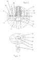
Figure 2 is a cross-sectional view of an enlarged section of the solenoid valve of the injector ofFigure 1 ; -
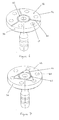
Figure 3 illustrates an armature arrangement of the solenoid valve ofFigure 2 ; -
Figures 4 to 6 illustrate various examples of armature arrangements useful for understanding the present invention; and -
Figures 7 to 9 illustrate various embodiments of armature arrangements according to the present invention. - An example of a known fuel injector suitable for delivering pressurised fuel from a high pressure accumulator to a cylinder of a diesel internal combustion engine is the fuel injector described in
EP 0798459 . Referring toFigures 1 and2 , the injector takes the form of asolenoid fuel injector 2 in which avalve needle 4 is moveable along the centre line of a body 6 and engageable with avalve seat 7 to control the flow of fuel from a high pressure fuel supply line 8 (referred to as the fuel supply line) through the body 6. The fuel supply line 8 terminates at anannular gallery 10 within which thevalve needle 4 is received. - The end of the needle remote from the
valve seat 7 extends within acontrol chamber 12, thecontrol chamber 12 being closed with aninsert member 14 and arranged to receive fuel from the fuel supply line 8 through arestrictor 16. Thevalve needle 4 is biased into engagement with thevalve seat 7 by means of a first spring 18 provided in thecontrol chamber 12. - A drilling in the
insert member 14 defines achamber 20 which communicates with an annular chamber 22 through apassage 23. Acontrol valve body 24 is arranged to engage aseating surface 25. Movement of thevalve body 24 serves to pressurise and depressurise thecontrol chamber 12. Thevalve body 24 is movable under the influence of asolenoid actuator 26 along a second axis, the second axis being offset from the centre line of the body 6. Thevalve body 24 is biased into engagement with theseating surface 25 by means of asecond spring 28. The annular chamber 22 is arranged to communicate with a suitable low pressure drain 29 when thevalve body 24 disengages theseating surface 25 such that communication between the low pressure drain 29 and thecontrol chamber 12 is established. The end of thevalve body 24 in proximity to thesolenoid actuator 26 carries anarmature 30 which can abut alift stop 32 defined by an underside of a valve housing 34, the lift stop 32 being arranged to terminate the lifting stroke of thearmature 30. - In use, when the
solenoid actuator 26 is de-energised, as in the position shown inFigure 1 , thevalve body 24 engages theseating surface 25 under the influence of thesecond spring 28 ensuring the fuel pressure in allchambers annular gallery 10 is equal. Thevalve needle 4 is biased into engagement with thevalve seat 7 by a combined force of the pressurised fuel in thecontrol chamber 12 and the first spring 18, the combined force being sufficient to overcome the upwards force acting on thevalve needle 4 due to the fuel pressure in theannular gallery 10, acting against anangled surface 36 of thevalve needle 4. - In order to permit delivery of fuel from the
injector 2, thesolenoid actuator 26 is energised to lift thevalve body 24 against the influence of thesecond spring 28 so that thevalve body 24 is lifted away from theseating surface 25. In so doing, fuel is allowed to flow from the annular chamber 22, and hence thechambers valve needle 4 from the fuel pressure in thechambers valve needle 4, thevalve needle 4 is lifted away from thevalve seat 7. - Referring also to
Figure 3 , thearmature 30 has anupper surface 38, which is provided with a sixvent holes 40 that are equi-angularly spaced around acavity 42 to extend through and emerge at theupper surface 38 of thearmature 30. Thecavity 42 is defined by a countersink provided in theupper surface 38 of thearmature 30 and is positioned in the centre of thearmature 30, thecavity 42 being arranged to receive ahead 44 of thevalve body 24 in a press-fit thereby securing the two components together. Thehead 44 of thevalve body 24 bears a corrugated region and, during assembly, anannular depression 43 is formed on the underside surface of thearmature 30 which causes the material of thearmature 30 to conform to the corrugated profile of thehead 44. Thehead 44 of thevalve body 24 is used to impact thelift stop 32 in order to control the distance travelled by thevalve body 24 during its lifting stroke. - A magnetic field is generated when the
solenoid actuator 26 is energised, the magnetic field passes through anouter pole area 46, through thearmature 30 and back through aninner pole area 48. An optimum magnetic force is generated when the inner andouter pole areas armature 30 is separated from thepoles armature 30 is required to move at high speeds and the fluid is expelled from the gap 50 when thevalve body 24 lifts and is sucked back into the gap 50 through the vent holes 40 and/or the inner andouter pole areas valve body 24 closes. - Current fuel injection systems are required to deliver increasingly higher injection pressures and so larger forces are required to lift the
valve body 24. Consequently the gap 50 which separates thearmature 30 from thepoles solenoid actuator 26 can generate to lift thevalve body 24. As thearmature 30 is moved, the fluid in theouter pole area 46 of the gap 50 moves relatively easily as it has a short path (as indicated by arrows A inFigure 2 ) and is able to pass two large perimeters, namely anouter perimeter 52 of thearmature 30 and aninner perimeter 54 of theouter pole area 46. The fluid in theinner pole area 48 of the gap 50 moves with more difficultly as it has a longer path (as indicated by arrows B inFigure 2 ) and can only pass a smallouter perimeter 56 of theinner pole area 48. Aninner perimeter 58 of theinner pole area 48 is of very small circumference and is blocked by thelift stop 32 when thevalve body 24 is lifted. - When the
fuel injector 2 is arranged so that the gap 50 is reduced, the fluid is not able to enter the gap 50 fast enough to fill theinner pole area 48 of the gap 50 when thevalve body 24 is closed against theseating surface 25. Consequently, the static pressure local to theinner pole area 48 is reduced and vapour bubbles or cavitation bubbles form. The formation of these bubbles takes place over a finite time period which is sensitive to the fluid properties, gas content and cleanliness. When the cavitation bubbles are exposed to a sufficiently high static pressure, as for example during the lifting stroke of thevalve body 24, said cavitation bubbles will collapse. The force exerted by the liquid rushing into the cavitation bubbles causes high localised pressures which affects the consistency of the shot-to-shot delivery of the injector and can lead to serious erosion of the boundary surfaces e.g. of thearmature 30. - The present invention improves on the above-described
armature 30 andvalve body 24 arrangement by modifying thearmature 30 to reduce the effects of cavitation on the shot-to-shot variability in the fuel delivery of the injector. - Referring to
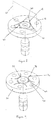
Figure 4 , in an example of an armature not forming part of the present invention, theupper surface 38 of thearmature 30 is not only provided with a plurality of vent holes 40 arranged in the manner described previously but is also provided with a series ofradial slots 60, theradial slots 60 being machined into theupper surface 38 of thearmature 30 from thecavity 42 to midway between alternate pairs of vent holes 40. Arrows C indicate the flow path that the fluid follows from the vent holes 40 to thecavity 42, at which point the fluid is distributed to theinner pole area 48. The additional fluid in theinner pole area 48 greatly reduces the fluid pressure drop experienced in this area during the closing stroke of thevalve body 24, thereby eliminating or substantially reducing the formation of cavitation bubbles in all but a small area of thelift stop 32. - It is considered desirable to maintain a rotational symmetry of the
radial slots 60 about anaxis 61 of thevalve body 24 in order to avoid magnetic side loads on thearmature 30. It should be appreciated that theaxis 61 of thevalve body 24 is coincident with an axis of thearmature 30. Furthermore, mirror symmetry of theradial slots 60 is also desirable about aplane 62 which extends vertically from theupper surface 38 of thearmature 30 thereby avoiding rotational forces on thearmature 30 when the fluid in theradial slots 60 flows from the vent holes 40 to thecavity 42. Theplane 62 is aligned with one of theradial slots 60 and intersects thevalve body axis 61. The three radial slot configuration of thearmature 30 inFigure 4 provides the requisite symmetry and an adequate flow path for the fluid but without a significant reduction of theinner pole area 48, thereby maintaining an optimum magnetic force and maximising the total magnetic flux capacity of the circuit. - The
radial slots 60 extend from thecavity 42 and terminate on the mid-plane between the vent holes 40. During the closing stroke of thevalve body 24, when thevalve body 24 impacts theseating surface 25, the mid-plane area between the vent holes 40 is known to be a low stressed area. Therefore, it is considered advantageous to terminate theradial slots 60 on the mid plane between the vent holes 40 in order to minimise the stresses induced by saidradial slots 60. - The use of a three radial slot configuration provides a further benefit of minimising the stress experienced by the
armature 30 during its lifting and closing strokes. A two radial slot configuration would tend to induce a bending vibration mode in thearmature 30, whereas the slots used in a configuration comprising more than threeradial slots 60 would have to be narrower in relation to their depth to maintain a sufficientinner pole area 48, resulting in a higher stress concentration when thearmature 30 flexes as thehead 44 of thevalve body 24 impacts thelift stop 32. - The above-described
radial slots 60 are preferably manufactured using a laser machining process. The laser machining process facilitates expeditious production of small slots in a precise manner. Furthermore, the laser machining process can form the optimum radius in the bottom of the radial slot, thereby minimising any associated stress concentrations. - Alternative manufacturing processes include: electric discharge machining; sawing with a small, narrow circular saw; or grinding with a narrow diamond or carbide coated cutting wheel.
-
Figure 5 shows another example of an armature that does not form part of the present invention, in which both theupper surface 38 of thearmature 30 and thehead 44 of thevalve body 24 are provided withradial slots 60 which are substantially aligned along a common axis. This radial slot configuration not only minimises the formation of cavitation bubbles during the closing stroke of thevalve body 24 but also improves the venting of the fluid during the lifting stroke of thevalve body 24 by providing anadditional flow path 64 to the middle of thehead 44 of thevalve body 24. A possible disadvantage of this radial slot configuration is that it reduces a beneficial squeeze film damping force that occurs on thelift stop 32 in the final stages of the lifting stroke of thevalve body 24. This can result in thevalve body 24 "bouncing" on thelift stop 32. The radial slot number, depth and/or width may therefore be varied to optimise the squeeze film damping force on thelift stop 32 in order to minimise the bouncing of thevalve body 24, whilst maximising the venting of the fluid from the vent holes 40. For example, theradial slots 60 in thehead 44 of thevalve body 24 may be shallow at thelift stop 32 and either taper or step to a larger depth in thearmature 30. Such variation in radial slot depth may also be applied to other designs ofradial slots 60 in order to optimise the flow through saidradial slots 60. -
Figure 6 shows another example of an armature that does not form part of the present invention in which theupper surface 38 of thearmature 30 is provided with a series ofradial slots 60 which extend from thecavity 42 through theouter perimeter 52 of saidarmature 30. An advantage of this armature it that it allows theradial slots 60 to be easily manufactured using manufacturing processes such as sawing or grinding. - A further advantage of this armature is that it provides additional flow paths in the
outer pole area 40 of thearmature 30. If the diameters of the vent holes 40 were reduced in order to, for example, optimise the inner andouter pole areas radial slots 60 ensure that the fluid is expelled from the gap 50. -
Figure 7 shows an embodiment of the present invention in which theupper surface 38 of thearmature 30 is provided with a plurality ofstraight slots 66, each of which is arranged to connect alternate ones of the vent holes 40 and thecavity 42. The vent holes 40 between said alternate ones connected to thecavity 42 remain isolated. This configuration ofstraight slots 66 ensures that the relatively high stress concentration at the edge of the vent holes 40 closest to thecavity 42 does not coincide with the stress concentration at the bottom of thestraight slots 66, thereby reducing any induced stresses. -
Figure 8 shows another embodiment of the present invention which is similar to that shown inFigure 7 . However, in this instance theupper surface 38 of thearmature 30 is provided with a plurality of curved or arcuatenon-radial slots 68, each of which is arranged to connect alternate ones of the vent holes 40 and thecavity 42. The vent holes 40 between said alternate ones connected to thecavity 42 remain isolated. This configuration ofslots 68 further separates the stress concentration at the bottom of theslots 68 from the relatively high stress concentration at the edge of the vent holes 40 closest to thecavity 42, thereby further reducing any induced stresses. -
Figure 9 shows another embodiment of the present invention in which theupper surface 38 of thearmature 30 is provided with a plurality of curved orarcuate slots 70, theslots 70 being arranged to connect the mid-planes either side of alternate ones of the vent holes 40 to thecavity 42. That is to say, theslots 70 do not intersect any of the vent holes 40. This configuration ofslots 70 thus avoids any possibility of the stress concentrations associated with the vent holes 40 and thecurved slots 70 accumulating. - A further advantage of the
curved slot 70 configuration, and the slot configurations ofFigures 7 and8 , is that the slots intersect thecavity 42 at a shallower angle when compared to the radial slot configurations, thereby reducing the stress concentration at saidintersection 72. A reduced stress concentration at theintersection 72 of thecavity 42 and curved slot means that the curved slot can afford to be manufactured narrower and deeper, thereby minimising the reduction in theinner pole area 48 and maintaining the total magnetic flux capacity of the circuit. - The examples shown in
Figures 5 and6 and the embodiments of the invention shown inFigures 7 to 9 maintain the advantages of having rotational and mirror symmetry of the slot configurations. However, it will be appreciated that theplane 62 described previously is applicable to theradial slot configurations 60; 60, 64 only and thespecific slot configurations Figures 7 to 9 have a mirror symmetry about asecond plane 67. With reference toFigure 8 , thesecond plane 67 extends vertically from theupper surface 38 of thearmature 30 and intersects thevalve body axis 61 and the centres of opposing vent holes 40. - Other configurations and type of formation in the
upper surface 38 of thearmature 30 and/or thehead 44 of thevalve body 24 are also envisaged, whilst still providing the benefit that an enhanced fluid flow from the vent holes 40 to thecavity 42 is permitted. For example, the slots could be arranged to extend between thecavity 42 and adjacent vent holes 40 thereby providing communication also between adjacent vent holes 40. In addition, although described in relation to a common rail injector, it will be appreciated that the invention is also applicable to other types of injectors, and indeed is applicable in non-fuel injector applications where there may be a desire for vent holes in the armature to be evacuated effectively. - It should be appreciated that although the embodiments have been described above as comprising an armature arrangement having an
armature 30 and aseparate valve body 24 coupled to it, this is not essential to the inventive concept and, instead, thearmature 30 and thevalve body 24 may be a unitary component i.e. thevalve body 24 is integral with thearmature 30.
Claims (9)
- An armature arrangement for a solenoid fuel injector comprising:an armature (30);one or more vent holes (40) in the armature (30);a valve body (24) associated with the armature (30); anda cavity (42) defined in the armature (30);wherein an upper surface (38) of the armature (30) is provided with at least one formation (66; 68; 70) to allow enhanced fluid flow from the one or more vent holes (40) to the cavity (42);characterised in that the at least one formation comprises a plurality of non-radial slots (66; 68; 70) connected to the cavity (42).
- The armature arrangement as claimed in claim 1, wherein the cavity (42) is defined by a countersink in the upper surface (38) of the armature (30).
- The armature arrangement as claimed in claim 1 or claim 2, wherein the at least one formation (66; 68; 70) has a rotational symmetry about a valve body axis (61).
- The armature arrangement as claimed in any one of claims 1 to 3, wherein the at least one formation (66; 68; 70) has a mirror symmetry about a plane along (or through) the valve body axis (61).
- The armature arrangement as claimed in any one of claims 1 to 4, wherein the plurality of slots (66; 68) are arranged to provide a fluid connection between the cavity (42) and alternate ones of the vent holes (40) or, alternatively, between the cavity (42) and adjacent ones of the vent holes (40).
- The armature arrangement as claimed in any one of claims 1 to 4, wherein the plurality of slots (70) are arranged to provide a fluid connection between either side of alternate ones of the vent holes (40) and the cavity (42).
- The armature arrangement as claimed in claims 5 or 6, wherein the plurality of slots (66; 68; 70) are substantially straight or curved.
- A method of manufacturing an armature arrangement as claimed in any one of claims 1 to 7, wherein the at least one formation (66; 68; 70) of the armature that allows enhanced fluid flow from the vent holes (40) to the cavity (42) is formed by way of a laser machining process.
- An injection device for use in a fuel injection system, the injection device including an actuator having an armature arrangement according to any one of claims 1 to 7, and a valve needle which is movable under the control of the actuator.
Priority Applications (2)
| Application Number | Priority Date | Filing Date | Title |
|---|---|---|---|
| AT08169457T ATE528499T1 (en) | 2008-11-19 | 2008-11-19 | ANCHOR ARRANGEMENT |
| EP08169457A EP2189648B1 (en) | 2008-11-19 | 2008-11-19 | Armature arrangement |
Applications Claiming Priority (1)
| Application Number | Priority Date | Filing Date | Title |
|---|---|---|---|
| EP08169457A EP2189648B1 (en) | 2008-11-19 | 2008-11-19 | Armature arrangement |
Publications (2)
| Publication Number | Publication Date |
|---|---|
| EP2189648A1 EP2189648A1 (en) | 2010-05-26 |
| EP2189648B1 true EP2189648B1 (en) | 2011-10-12 |
Family
ID=40577985
Family Applications (1)
| Application Number | Title | Priority Date | Filing Date |
|---|---|---|---|
| EP08169457A Active EP2189648B1 (en) | 2008-11-19 | 2008-11-19 | Armature arrangement |
Country Status (2)
| Country | Link |
|---|---|
| EP (1) | EP2189648B1 (en) |
| AT (1) | ATE528499T1 (en) |
Families Citing this family (4)
| Publication number | Priority date | Publication date | Assignee | Title |
|---|---|---|---|---|
| US20120103308A1 (en) * | 2010-10-28 | 2012-05-03 | Caterpillar, Inc. | Two-Way Valve Orifice Plate for a Fuel Injector |
| CN102758712A (en) * | 2011-04-29 | 2012-10-31 | 北京亚新科天纬油泵油嘴股份有限公司 | Fuel injection executing valve |
| GB2570636A (en) * | 2018-01-17 | 2019-08-07 | Delphi Automotive Systems Lux | Fuel Injector |
| US11840993B1 (en) * | 2023-02-01 | 2023-12-12 | Caterpillar Inc. | Fuel-actuated fuel injector having cooling fuel circuit and method |
Family Cites Families (9)
| Publication number | Priority date | Publication date | Assignee | Title |
|---|---|---|---|---|
| US5636615A (en) | 1995-02-21 | 1997-06-10 | Diesel Technology Company | Fuel pumping and injection systems |
| GB9606803D0 (en) | 1996-03-30 | 1996-06-05 | Lucas Ind Plc | Injection nozzle |
| DE10018304A1 (en) * | 2000-04-13 | 2001-10-25 | Bosch Gmbh Robert | Armature plate of a switching magnet, in particular for diesel fuel injectors, and method for producing such an armature plate |
| ITTO20010970A1 (en) * | 2001-10-12 | 2003-04-12 | Fiat Ricerche | FUEL INJECTOR FOR AN INTERNAL COMBUSTION ENGINE. |
| JP4026592B2 (en) * | 2003-12-24 | 2007-12-26 | 株式会社デンソー | Fuel injection valve |
| DE102005020360A1 (en) * | 2005-05-02 | 2006-11-09 | Robert Bosch Gmbh | Valve for controlling an injection valve of an internal combustion engine |
| JP2007064364A (en) | 2005-08-31 | 2007-03-15 | Denso Corp | Solenoid valve |
| DE102005061781A1 (en) * | 2005-12-23 | 2007-06-28 | Schaeffler Kg | Injector for automotive fuel injection system has laser-cut micro detents in contact zone sidewall around piston |
| JP4719140B2 (en) * | 2006-12-20 | 2011-07-06 | 三菱重工業株式会社 | Electromagnetic valve device and fuel injection device for an engine equipped with the same |
-
2008
- 2008-11-19 AT AT08169457T patent/ATE528499T1/en not_active IP Right Cessation
- 2008-11-19 EP EP08169457A patent/EP2189648B1/en active Active
Also Published As
| Publication number | Publication date |
|---|---|
| EP2189648A1 (en) | 2010-05-26 |
| ATE528499T1 (en) | 2011-10-15 |
Similar Documents
| Publication | Publication Date | Title |
|---|---|---|
| EP1081372B1 (en) | Fuel injection device | |
| EP2189648B1 (en) | Armature arrangement | |
| US20060157582A1 (en) | Fuel injector reducing stress concentration | |
| US20110180634A1 (en) | Nozzle body, nozzle assembly and fuel injector, and method for producing a nozzle body | |
| KR101224409B1 (en) | Fuel injector | |
| US6955114B2 (en) | Three way valve and electro-hydraulic actuator using same | |
| JP2005180407A (en) | Fuel injection valve | |
| US7360722B2 (en) | Fuel injector with grooved check member | |
| US7007869B2 (en) | Seal between elements of a fuel-injection nozzle for an internal combustion engine | |
| US7578450B2 (en) | Fuel injector with grooved check member | |
| EP1063421A2 (en) | Fuel injector | |
| JP6741052B2 (en) | Fuel injection valve | |
| US9719476B2 (en) | B-LCCR injector pilot valve orifice, armature and plunger guide arrangement | |
| US7108206B2 (en) | Valve assembly and fuel injector using same | |
| JP2007297962A (en) | Fuel injection nozzle | |
| JP4078320B2 (en) | Poppet valve device and electronically controlled fuel injection device including the same | |
| JP5237054B2 (en) | Control valve structure of accumulator fuel injector | |
| WO2015020940A1 (en) | Fuel injector including a control valve having a guided check valve ball | |
| WO2007024418A1 (en) | Fuel injector with grooved check member | |
| JP6724959B2 (en) | Fuel injection valve | |
| JP6708235B2 (en) | Fuel injection valve | |
| JP6708236B2 (en) | Fuel injection valve | |
| EP2083165A1 (en) | Injection nozzle | |
| US20040227018A1 (en) | Modular fuel injector for an internal combustion engine | |
| KR100484019B1 (en) | Stress-reducing structure for high-pressure oil feed conduit intersection in fuel injection valve |
Legal Events
| Date | Code | Title | Description |
|---|---|---|---|
| PUAI | Public reference made under article 153(3) epc to a published international application that has entered the european phase |
Free format text: ORIGINAL CODE: 0009012 |
|
| AK | Designated contracting states |
Kind code of ref document: A1 Designated state(s): AT BE BG CH CY CZ DE DK EE ES FI FR GB GR HR HU IE IS IT LI LT LU LV MC MT NL NO PL PT RO SE SI SK TR |
|
| AX | Request for extension of the european patent |
Extension state: AL BA MK RS |
|
| 17P | Request for examination filed |
Effective date: 20101126 |
|
| AKX | Designation fees paid |
Designated state(s): AT BE BG CH CY CZ DE DK EE ES FI FR GB GR HR HU IE IS IT LI LT LU LV MC MT NL NO PL PT RO SE SI SK TR |
|
| AXX | Extension fees paid |
Extension state: AL Payment date: 20101126 Extension state: BA Payment date: 20101126 Extension state: MK Payment date: 20101126 Extension state: RS Payment date: 20101126 |
|
| 17Q | First examination report despatched |
Effective date: 20110118 |
|
| GRAP | Despatch of communication of intention to grant a patent |
Free format text: ORIGINAL CODE: EPIDOSNIGR1 |
|
| GRAS | Grant fee paid |
Free format text: ORIGINAL CODE: EPIDOSNIGR3 |
|
| GRAA | (expected) grant |
Free format text: ORIGINAL CODE: 0009210 |
|
| AK | Designated contracting states |
Kind code of ref document: B1 Designated state(s): AT BE BG CH CY CZ DE DK EE ES FI FR GB GR HR HU IE IS IT LI LT LU LV MC MT NL NO PL PT RO SE SI SK TR |
|
| AX | Request for extension of the european patent |
Extension state: AL BA MK RS |
|
| REG | Reference to a national code |
Ref country code: GB Ref legal event code: FG4D |
|
| REG | Reference to a national code |
Ref country code: CH Ref legal event code: EP |
|
| REG | Reference to a national code |
Ref country code: IE Ref legal event code: FG4D |
|
| REG | Reference to a national code |
Ref country code: DE Ref legal event code: R096 Ref document number: 602008010358 Country of ref document: DE Effective date: 20111208 |
|
| REG | Reference to a national code |
Ref country code: NL Ref legal event code: VDEP Effective date: 20111012 |
|
| LTIE | Lt: invalidation of european patent or patent extension |
Effective date: 20111012 |
|
| REG | Reference to a national code |
Ref country code: AT Ref legal event code: MK05 Ref document number: 528499 Country of ref document: AT Kind code of ref document: T Effective date: 20111012 |
|
| PG25 | Lapsed in a contracting state [announced via postgrant information from national office to epo] |
Ref country code: LT Free format text: LAPSE BECAUSE OF FAILURE TO SUBMIT A TRANSLATION OF THE DESCRIPTION OR TO PAY THE FEE WITHIN THE PRESCRIBED TIME-LIMIT Effective date: 20111012 Ref country code: BE Free format text: LAPSE BECAUSE OF FAILURE TO SUBMIT A TRANSLATION OF THE DESCRIPTION OR TO PAY THE FEE WITHIN THE PRESCRIBED TIME-LIMIT Effective date: 20111012 Ref country code: NO Free format text: LAPSE BECAUSE OF FAILURE TO SUBMIT A TRANSLATION OF THE DESCRIPTION OR TO PAY THE FEE WITHIN THE PRESCRIBED TIME-LIMIT Effective date: 20120112 Ref country code: IS Free format text: LAPSE BECAUSE OF FAILURE TO SUBMIT A TRANSLATION OF THE DESCRIPTION OR TO PAY THE FEE WITHIN THE PRESCRIBED TIME-LIMIT Effective date: 20120212 |
|
| PG25 | Lapsed in a contracting state [announced via postgrant information from national office to epo] |
Ref country code: NL Free format text: LAPSE BECAUSE OF FAILURE TO SUBMIT A TRANSLATION OF THE DESCRIPTION OR TO PAY THE FEE WITHIN THE PRESCRIBED TIME-LIMIT Effective date: 20111012 Ref country code: LV Free format text: LAPSE BECAUSE OF FAILURE TO SUBMIT A TRANSLATION OF THE DESCRIPTION OR TO PAY THE FEE WITHIN THE PRESCRIBED TIME-LIMIT Effective date: 20111012 Ref country code: SI Free format text: LAPSE BECAUSE OF FAILURE TO SUBMIT A TRANSLATION OF THE DESCRIPTION OR TO PAY THE FEE WITHIN THE PRESCRIBED TIME-LIMIT Effective date: 20111012 Ref country code: SE Free format text: LAPSE BECAUSE OF FAILURE TO SUBMIT A TRANSLATION OF THE DESCRIPTION OR TO PAY THE FEE WITHIN THE PRESCRIBED TIME-LIMIT Effective date: 20111012 Ref country code: PT Free format text: LAPSE BECAUSE OF FAILURE TO SUBMIT A TRANSLATION OF THE DESCRIPTION OR TO PAY THE FEE WITHIN THE PRESCRIBED TIME-LIMIT Effective date: 20120213 Ref country code: HR Free format text: LAPSE BECAUSE OF FAILURE TO SUBMIT A TRANSLATION OF THE DESCRIPTION OR TO PAY THE FEE WITHIN THE PRESCRIBED TIME-LIMIT Effective date: 20111012 Ref country code: GR Free format text: LAPSE BECAUSE OF FAILURE TO SUBMIT A TRANSLATION OF THE DESCRIPTION OR TO PAY THE FEE WITHIN THE PRESCRIBED TIME-LIMIT Effective date: 20120113 |
|
| PG25 | Lapsed in a contracting state [announced via postgrant information from national office to epo] |
Ref country code: MC Free format text: LAPSE BECAUSE OF NON-PAYMENT OF DUE FEES Effective date: 20111130 Ref country code: CY Free format text: LAPSE BECAUSE OF FAILURE TO SUBMIT A TRANSLATION OF THE DESCRIPTION OR TO PAY THE FEE WITHIN THE PRESCRIBED TIME-LIMIT Effective date: 20111012 |
|
| PG25 | Lapsed in a contracting state [announced via postgrant information from national office to epo] |
Ref country code: BG Free format text: LAPSE BECAUSE OF FAILURE TO SUBMIT A TRANSLATION OF THE DESCRIPTION OR TO PAY THE FEE WITHIN THE PRESCRIBED TIME-LIMIT Effective date: 20120112 Ref country code: CZ Free format text: LAPSE BECAUSE OF FAILURE TO SUBMIT A TRANSLATION OF THE DESCRIPTION OR TO PAY THE FEE WITHIN THE PRESCRIBED TIME-LIMIT Effective date: 20111012 Ref country code: SK Free format text: LAPSE BECAUSE OF FAILURE TO SUBMIT A TRANSLATION OF THE DESCRIPTION OR TO PAY THE FEE WITHIN THE PRESCRIBED TIME-LIMIT Effective date: 20111012 Ref country code: EE Free format text: LAPSE BECAUSE OF FAILURE TO SUBMIT A TRANSLATION OF THE DESCRIPTION OR TO PAY THE FEE WITHIN THE PRESCRIBED TIME-LIMIT Effective date: 20111012 Ref country code: DK Free format text: LAPSE BECAUSE OF FAILURE TO SUBMIT A TRANSLATION OF THE DESCRIPTION OR TO PAY THE FEE WITHIN THE PRESCRIBED TIME-LIMIT Effective date: 20111012 |
|
| PLBE | No opposition filed within time limit |
Free format text: ORIGINAL CODE: 0009261 |
|
| STAA | Information on the status of an ep patent application or granted ep patent |
Free format text: STATUS: NO OPPOSITION FILED WITHIN TIME LIMIT |
|
| REG | Reference to a national code |
Ref country code: IE Ref legal event code: MM4A |
|
| PG25 | Lapsed in a contracting state [announced via postgrant information from national office to epo] |
Ref country code: PL Free format text: LAPSE BECAUSE OF FAILURE TO SUBMIT A TRANSLATION OF THE DESCRIPTION OR TO PAY THE FEE WITHIN THE PRESCRIBED TIME-LIMIT Effective date: 20111012 Ref country code: IT Free format text: LAPSE BECAUSE OF FAILURE TO SUBMIT A TRANSLATION OF THE DESCRIPTION OR TO PAY THE FEE WITHIN THE PRESCRIBED TIME-LIMIT Effective date: 20111012 Ref country code: RO Free format text: LAPSE BECAUSE OF FAILURE TO SUBMIT A TRANSLATION OF THE DESCRIPTION OR TO PAY THE FEE WITHIN THE PRESCRIBED TIME-LIMIT Effective date: 20111012 |
|
| 26N | No opposition filed |
Effective date: 20120713 |
|
| PG25 | Lapsed in a contracting state [announced via postgrant information from national office to epo] |
Ref country code: IE Free format text: LAPSE BECAUSE OF NON-PAYMENT OF DUE FEES Effective date: 20111119 |
|
| REG | Reference to a national code |
Ref country code: DE Ref legal event code: R097 Ref document number: 602008010358 Country of ref document: DE Effective date: 20120713 |
|
| PG25 | Lapsed in a contracting state [announced via postgrant information from national office to epo] |
Ref country code: AT Free format text: LAPSE BECAUSE OF FAILURE TO SUBMIT A TRANSLATION OF THE DESCRIPTION OR TO PAY THE FEE WITHIN THE PRESCRIBED TIME-LIMIT Effective date: 20111012 |
|
| PG25 | Lapsed in a contracting state [announced via postgrant information from national office to epo] |
Ref country code: MT Free format text: LAPSE BECAUSE OF FAILURE TO SUBMIT A TRANSLATION OF THE DESCRIPTION OR TO PAY THE FEE WITHIN THE PRESCRIBED TIME-LIMIT Effective date: 20111012 |
|
| PG25 | Lapsed in a contracting state [announced via postgrant information from national office to epo] |
Ref country code: ES Free format text: LAPSE BECAUSE OF FAILURE TO SUBMIT A TRANSLATION OF THE DESCRIPTION OR TO PAY THE FEE WITHIN THE PRESCRIBED TIME-LIMIT Effective date: 20120123 |
|
| PG25 | Lapsed in a contracting state [announced via postgrant information from national office to epo] |
Ref country code: LU Free format text: LAPSE BECAUSE OF NON-PAYMENT OF DUE FEES Effective date: 20111119 |
|
| PG25 | Lapsed in a contracting state [announced via postgrant information from national office to epo] |
Ref country code: FI Free format text: LAPSE BECAUSE OF FAILURE TO SUBMIT A TRANSLATION OF THE DESCRIPTION OR TO PAY THE FEE WITHIN THE PRESCRIBED TIME-LIMIT Effective date: 20111012 |
|
| REG | Reference to a national code |
Ref country code: CH Ref legal event code: PL |
|
| GBPC | Gb: european patent ceased through non-payment of renewal fee |
Effective date: 20121119 |
|
| PG25 | Lapsed in a contracting state [announced via postgrant information from national office to epo] |
Ref country code: CH Free format text: LAPSE BECAUSE OF NON-PAYMENT OF DUE FEES Effective date: 20121130 Ref country code: LI Free format text: LAPSE BECAUSE OF NON-PAYMENT OF DUE FEES Effective date: 20121130 |
|
| PG25 | Lapsed in a contracting state [announced via postgrant information from national office to epo] |
Ref country code: TR Free format text: LAPSE BECAUSE OF FAILURE TO SUBMIT A TRANSLATION OF THE DESCRIPTION OR TO PAY THE FEE WITHIN THE PRESCRIBED TIME-LIMIT Effective date: 20111012 |
|
| PG25 | Lapsed in a contracting state [announced via postgrant information from national office to epo] |
Ref country code: HU Free format text: LAPSE BECAUSE OF FAILURE TO SUBMIT A TRANSLATION OF THE DESCRIPTION OR TO PAY THE FEE WITHIN THE PRESCRIBED TIME-LIMIT Effective date: 20111012 |
|
| PG25 | Lapsed in a contracting state [announced via postgrant information from national office to epo] |
Ref country code: GB Free format text: LAPSE BECAUSE OF NON-PAYMENT OF DUE FEES Effective date: 20121119 |
|
| REG | Reference to a national code |
Ref country code: FR Ref legal event code: TP Owner name: DELPHI INTERNATIONAL OPERATIONS LUXEMBOURG S.A, LU Effective date: 20140516 |
|
| REG | Reference to a national code |
Ref country code: DE Ref legal event code: R081 Ref document number: 602008010358 Country of ref document: DE Owner name: DELPHI INTERNATIONAL OPERATIONS LUXEMBOURG S.A, LU Free format text: FORMER OWNER: DELPHI TECHNOLOGIES HOLDING S.A.R.L., BASCHARAGE, LU Effective date: 20140702 |
|
| REG | Reference to a national code |
Ref country code: FR Ref legal event code: PLFP Year of fee payment: 8 |
|
| REG | Reference to a national code |
Ref country code: FR Ref legal event code: PLFP Year of fee payment: 9 |
|
| REG | Reference to a national code |
Ref country code: FR Ref legal event code: PLFP Year of fee payment: 10 |
|
| REG | Reference to a national code |
Ref country code: DE Ref legal event code: R081 Ref document number: 602008010358 Country of ref document: DE Owner name: DELPHI TECHNOLOGIES IP LIMITED, BB Free format text: FORMER OWNER: DELPHI INTERNATIONAL OPERATIONS LUXEMBOURG S.A R.L., BASCHARAGE, LU |
|
| PGFP | Annual fee paid to national office [announced via postgrant information from national office to epo] |
Ref country code: FR Payment date: 20201125 Year of fee payment: 13 |
|
| PG25 | Lapsed in a contracting state [announced via postgrant information from national office to epo] |
Ref country code: FR Free format text: LAPSE BECAUSE OF NON-PAYMENT OF DUE FEES Effective date: 20211130 |
|
| P01 | Opt-out of the competence of the unified patent court (upc) registered |
Effective date: 20230327 |
|
| PGFP | Annual fee paid to national office [announced via postgrant information from national office to epo] |
Ref country code: DE Payment date: 20231010 Year of fee payment: 16 |
|
| REG | Reference to a national code |
Ref country code: DE Ref legal event code: R081 Ref document number: 602008010358 Country of ref document: DE Owner name: PHINIA DELPHI LUXEMBOURG SARL, LU Free format text: FORMER OWNER: DELPHI TECHNOLOGIES IP LIMITED, ST. MICHAEL, BB |