EP2189646B1 - Verstellbare Rotorschaufelanordnung in einer Gasturbine - Google Patents
Verstellbare Rotorschaufelanordnung in einer Gasturbine Download PDFInfo
- Publication number
- EP2189646B1 EP2189646B1 EP09252354.7A EP09252354A EP2189646B1 EP 2189646 B1 EP2189646 B1 EP 2189646B1 EP 09252354 A EP09252354 A EP 09252354A EP 2189646 B1 EP2189646 B1 EP 2189646B1
- Authority
- EP
- European Patent Office
- Prior art keywords
- variable pitch
- rotor
- rotor arrangement
- arrangement
- actuator
- Prior art date
- Legal status (The legal status is an assumption and is not a legal conclusion. Google has not performed a legal analysis and makes no representation as to the accuracy of the status listed.)
- Not-in-force
Links
Images

Classifications
-
- F—MECHANICAL ENGINEERING; LIGHTING; HEATING; WEAPONS; BLASTING
- F02—COMBUSTION ENGINES; HOT-GAS OR COMBUSTION-PRODUCT ENGINE PLANTS
- F02K—JET-PROPULSION PLANTS
- F02K3/00—Plants including a gas turbine driving a compressor or a ducted fan
- F02K3/02—Plants including a gas turbine driving a compressor or a ducted fan in which part of the working fluid by-passes the turbine and combustion chamber
- F02K3/025—Plants including a gas turbine driving a compressor or a ducted fan in which part of the working fluid by-passes the turbine and combustion chamber the by-pass flow being at least partly used to create an independent thrust component
-
- B—PERFORMING OPERATIONS; TRANSPORTING
- B64—AIRCRAFT; AVIATION; COSMONAUTICS
- B64C—AEROPLANES; HELICOPTERS
- B64C11/00—Propellers, e.g. of ducted type; Features common to propellers and rotors for rotorcraft
- B64C11/30—Blade pitch-changing mechanisms
- B64C11/38—Blade pitch-changing mechanisms fluid, e.g. hydraulic
- B64C11/385—Blade pitch-changing mechanisms fluid, e.g. hydraulic comprising feathering, braking or stopping systems
-
- B—PERFORMING OPERATIONS; TRANSPORTING
- B64—AIRCRAFT; AVIATION; COSMONAUTICS
- B64C—AEROPLANES; HELICOPTERS
- B64C11/00—Propellers, e.g. of ducted type; Features common to propellers and rotors for rotorcraft
- B64C11/30—Blade pitch-changing mechanisms
- B64C11/38—Blade pitch-changing mechanisms fluid, e.g. hydraulic
- B64C11/40—Blade pitch-changing mechanisms fluid, e.g. hydraulic automatic
-
- B—PERFORMING OPERATIONS; TRANSPORTING
- B64—AIRCRAFT; AVIATION; COSMONAUTICS
- B64C—AEROPLANES; HELICOPTERS
- B64C11/00—Propellers, e.g. of ducted type; Features common to propellers and rotors for rotorcraft
- B64C11/46—Arrangements of, or constructional features peculiar to, multiple propellers
- B64C11/48—Units of two or more coaxial propellers
-
- B—PERFORMING OPERATIONS; TRANSPORTING
- B64—AIRCRAFT; AVIATION; COSMONAUTICS
- B64D—EQUIPMENT FOR FITTING IN OR TO AIRCRAFT; FLIGHT SUITS; PARACHUTES; ARRANGEMENT OR MOUNTING OF POWER PLANTS OR PROPULSION TRANSMISSIONS IN AIRCRAFT
- B64D27/00—Arrangement or mounting of power plants in aircraft; Aircraft characterised by the type or position of power plants
- B64D27/02—Aircraft characterised by the type or position of power plants
- B64D27/30—Aircraft characterised by electric power plants
- B64D27/33—Hybrid electric aircraft
-
- B—PERFORMING OPERATIONS; TRANSPORTING
- B64—AIRCRAFT; AVIATION; COSMONAUTICS
- B64D—EQUIPMENT FOR FITTING IN OR TO AIRCRAFT; FLIGHT SUITS; PARACHUTES; ARRANGEMENT OR MOUNTING OF POWER PLANTS OR PROPULSION TRANSMISSIONS IN AIRCRAFT
- B64D27/00—Arrangement or mounting of power plants in aircraft; Aircraft characterised by the type or position of power plants
- B64D27/02—Aircraft characterised by the type or position of power plants
- B64D27/026—Aircraft characterised by the type or position of power plants comprising different types of power plants, e.g. combination of a piston engine and a gas-turbine
-
- F—MECHANICAL ENGINEERING; LIGHTING; HEATING; WEAPONS; BLASTING
- F05—INDEXING SCHEMES RELATING TO ENGINES OR PUMPS IN VARIOUS SUBCLASSES OF CLASSES F01-F04
- F05D—INDEXING SCHEME FOR ASPECTS RELATING TO NON-POSITIVE-DISPLACEMENT MACHINES OR ENGINES, GAS-TURBINES OR JET-PROPULSION PLANTS
- F05D2260/00—Function
- F05D2260/70—Adjusting of angle of incidence or attack of rotating blades
- F05D2260/76—Adjusting of angle of incidence or attack of rotating blades the adjusting mechanism using auxiliary power sources
Definitions
- This invention relates to a variable pitch rotor arrangement comprising a bladed rotor provided with a primary actuator for displacing a component of the rotor under the control of primary control means.
- the present invention is particularly, although not exclusively, concerned with such a variable pitch rotor arrangement in the form of a gas turbine engine, in which the bladed rotor is provided with variable pitch blades.
- a known type of gas turbine engine is a propeller gas turbine engine or turboprop.
- This works in conventional form, whereby a core engine comprising compressors, combustion equipment and turbines drives one or more propeller rotor stages via a shaft from a free power, or low-pressure, turbine.
- the propeller rotor stage or stages may be situated at the front or rear of the engine, with respect to the direction of airflow through the engine.
- the propeller rotor blades extend radially outwardly beyond the core engine.
- Each blade is of variable pitch, and for this purpose is pivotable about its own longitudinal axis so as to change its angle of attack relative to the airflow. This variable pitch enables more efficient operation at a variety of operating conditions since the incident angle between the airflow and the blade surface can be optimised for the given airspeed and operating mode of the engine and aircraft.
- back-up systems which can assume control of blade pitch in the event of failure of the main pitch control system.
- Such back-up systems can provide operative pitch control in that they can enable control of the blade pitch over at least part of the normal range of blade movement.
- back-up systems cause the propeller rotor to assume a failsafe configuration in which the blades are feathered, i.e. are generally aligned with the direction of incident air flow.
- a disadvantage of current back-up systems is that they utilise at least part of the main pitch control system, and consequently are not fully independent. As a result, failure of components which are common to both the main and back-up control systems results in total inability to control the blade pitch.
- United States patent application US 2003/180146 A1 discloses a propeller control system that comprises a propeller shaft, a pitch change valve, and a transfer bearing.
- the propeller control system provides for actuation through supply pressure only.
- a feather override mode is provided by energising a feathering solenoid.
- United States patent US 4878809 A discloses a pitch controller for controlling the pitch of a plurality of blades of a fan powered by a turbine propulsion engine, with a pitch adjusting device having an input for controlling the pitch of the blades.
- United States patent application US 2005/135929 A1 discloses a system and a method for providing pressurised oil during non-feathered in-flight shutdown conditions in a variable-pitch aircraft propeller engine.
- a secondary pumping means provides pressurised oil substantially independent of an engine main oil circuit.
- variable pitch rotor arrangement comprising a bladed rotor provided with a primary actuator for displacing a component of the rotor under the control of primary control means, the arrangement further comprising:
- operative failure means any failure, including failure in the primary actuator or the primary control means, which results in failure of the primary actuator to displace the component in the desired manner.
- the power generating means may comprise an electrical generator for supplying electrical power to an electrical actuator.
- the power generating means may be a hydraulic pump
- the secondary actuator may be a hydraulic actuator.
- the pump may be a swashplate pump, in which case the pump may be permanently driven when the rotor rotates relatively to the further part of the arrangement.
- the swashplate of the pump may be in the "flat" or non-inclined orientation, in which the pump delivery is zero.
- the secondary control means causes displacement of the swashplate to an inclined orientation to deliver hydraulic fluid under pressure to the secondary actuator.
- the supply and delivery sides of the pump may be interconnected by a bypass duct provided with a pressure relief valve. Consequently, when the secondary actuator reaches an end position, increased pressure on the delivery side of the pump will cause the pressure relief valve to open, allowing hydraulic fluid to recirculate from the delivery side to the supply side of the pump.
- the secondary control means may be responsive to a pressure in a hydraulic circuit of the primary actuator, so that the failure signal is constituted by a pressure in the hydraulic circuit below a predetermined value.
- the arrangement is a propulsive device
- the rotor is a bladed rotor, with the component being a variable pitch blade of the rotor which is displaceable by the primary and secondary actuators to vary the blade pitch.
- the secondary actuator may be operatively connected to the blade to displace the blade to a feathered condition in response to the failure signal.
- the bladed rotor may be one of pair of contra-rotating rotors, in which case the power generating means may be driven by relative rotation between the two rotors of the pair.
- the power generating means may have an input shaft carrying a pinion which engages a ring gear mounted on the other rotor.
- a twin-spooled, contra-rotating propeller gas turbine engine is generally indicated at 10 and has a principal rotational axis 9.
- the engine 10 comprises a core engine 11 having, in axial flow series, an air intake 12, an intermediate pressure compressor 14, a high-pressure compressor 15, combustion equipment 16, a high-pressure turbine 17, an intermediate pressure turbine 18, a free power (or low-pressure) turbine 19 and a core exhaust nozzle 20.
- a nacelle 21 generally surrounds the core engine 11 and defines the intake 12, the nozzle 20 and a core exhaust duct 22.
- the engine 10 also comprises two contra-rotating propeller stages 23, 24 attached to and driven by the free power turbine 19 via a shaft 26 and a differential gear box (not shown).
- the gas turbine engine 10 works in a conventional manner so that air entering the intake 12 is accelerated and compressed by the intermediate pressure compressor 14 and directed into the high-pressure compressor 15 where further compression takes place.
- the compressed air exhausted from the high-pressure compressor 15 is directed into the combustion equipment 16 where it is mixed with fuel and the mixture combusted.
- the resultant hot combustion products then expand through, and thereby drive the high-pressure, intermediate pressure and free power turbines 17, 18, 19 before being exhausted through the nozzle 20 to provide some propulsive thrust.
- the high-pressure, intermediate pressure and free power turbines 17, 18, 19 respectively drive the high and intermediate pressure compressors 15, 14 and the propeller stages 23, 24 by suitable interconnecting shafts.
- the propeller stages 23, 24 normally provide the majority of the propulsive thrust.
- the propellers 23, 24 rotate in opposite senses so that one rotates clockwise and the other anticlockwise around the engine's rotational axis 9.
- Each propeller stage 23, 24 comprises a rotor in the form of a bladed rotor having displaceable components in the form of variable pitch blades 6, 8.
- Pitch angle is defined as shown in Figure 2 wherein one of the blades 8 of the rotor 24 is shown, viewed from its radially outer end.
- the blade 8 is one of a set of rotor blades on the rotor 24, which rotates clockwise as viewed from the left.
- Pitch angle ⁇ is measured clockwise from the top dead centre, ie from the blade travel direction V.
- the rotors 23, 24 are each provided with a primary actuator and primary control means (not shown) for controlling the pitch of the blades 6, 8.
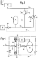
- at least one of the rotors 23, 24 (the rear rotor 24 in the present embodiment) is provided with a back-up pitch control system represented in Figures 3 and 4 .
- the hydraulic circuit represented in Figure 3 comprises a hydraulic actuator 30 which is connected, by an appropriate linkage, to the blades 8 of the rotor 24 so that operation of the actuator 30 displaces the blades 8 in unison about their lengthwise axes to vary their pitch angle.
- a pump 32 is connected at its delivery side to the actuator 30 by a conduit 34.
- the supply side of the pump 32 is connected by a conduit 36 to a hydraulic circuit 38 of the primary pitch control system.
- a non-return valve 39 is provided in the conduit 36 to prevent reverse flow along the conduit 36 towards the hydraulic circuit 38.
- the supply and delivery sides of the pump 32 are interconnected by a bypass conduit 40 which extends between the conduits 34 and 36 and includes a pressure relief valve 42 responsive to the pressure in the conduit 34.
- An accumulator 44 is in communication with the conduit 36.
- the pump 32 is a swashplate pump having an input shaft 46.
- the inclination of the swashplate is adjusted by secondary control means which is responsive to a hydraulic pressure of the hydraulic circuit 38 of the primary pitch control system. This pressure is transmitted along a sensing conduit 48 to the secondary control means in the pump 32.
- the pump 32 is mounted on the rotor 24 at a position away from the engine axis 9.
- a ring gear 56 centred on the engine axis 9, is mounted on the rotor 23, and so rotates with that rotor.
- the drive shaft 46 of the pump 32 carries a pinion 58 which meshes with internal teeth of the ring 56. It will therefore be appreciated that, as the rotors 23 and 24 rotate in opposite directions, the input shaft 46 is rotated to drive the pump 32.
- the pressure in the sensing conduit 48 is at a working level, above a predetermined threshold. While this pressure is maintained, the swashplate of the pump 32 is maintained in a non-inclined orientation, so that no hydraulic fluid is delivered by the pump 32 through the conduit 34 to the actuator 30. Consequently, the actuator 30 has no effect on the pitch angle of the blades 8. Nevertheless, by virtue of the engagement between the ring gear 56 and the pinion 58, the motor 32 is permanently driven whenever there is rotation between the rotors 23 and 24. Hydraulic fluid is present in the circuit represented in Figure 3 , including the accumulator 44, this hydraulic fluid being supplied from the hydraulic circuit 38 of the primary pitch control system through the non-return valve 39.
- the actuator 30 When the actuator 30 reaches the limit condition, the continued operation of the pump 32 causes the pressure in the conduit 34 to increase. This increased pressure is transmitted to the pressure relief valve 42 which, at a predetermined pressure, opens to permit the hydraulic fluid to recirculate through the bypass duct 40 to the conduit 36 and the supply side of the pump 32. Consequently, the actuator 30 remains locked in the position corresponding to feathering of the blades 8, while hydraulic fluid is recirculated by the pump 32.
- any leakage of hydraulic fluid from the circuit shown in Figure 3 can be made up from the accumulator 44, even while the back-up system is operating.
- the back-up system can thus remain in use until the engine is stopped, or until the primary pitch control system is restored to operation.
- any loss of hydraulic fluid from the back-up hydraulic circuit can be restored from the hydraulic circuit 38 of the primary pitch control system through the non-return valve 39.
- fluid pressure is restored to the sensing conduit 48, which automatically causes the swashplate of the pump 32 to return to the non-inclined orientation, so that fluid ceases to be delivered through the conduit 34 to the actuator 30, and the feathering actuation of the blades 8 is terminated.
- sensing conduit 48 will transmit a failure signal to the pump 32 in the event of a loss of pressure in the hydraulic circuit 38 of the primary pitch control system, provision may also be made for manual or automatic release of pressure in the sensing conduit 48, so that the back-up system can be activated independently of any loss of pressure in the primary system.
- the present invention thus provides a back-up system for blade pitch control which is fully independent of the primary pitch control system.
- the back-up system works across the mechanical interface between the contra-rotating rotors 23, 24.
- the back-up system responds to loss of hydraulic pressure in the primary system, it will operate in the event that hydraulic supply to the primary system fails.
- the back-up system requires no transmission of electrical signals across rotating or static interfaces between components, and is consequently reliable in operation.
- the pump 32 is driven by relative rotation between the rotors 23 and 24, significant pressures can be generated enabling high actuation forces to be applied to the blades 8. Consequently, in the event of mechanical failure in the primary pitch control system, sufficient forces can be applied by the secondary actuator 30 to force the blades 8 into the feathered condition.
- the back-up system can be configured to vary the pitch of the blades 8 to any desired default position.
- bypass conduit 40 and the pressure relief valve 42 it would be possible to apply negative feed back to the pump 32 when the actuator 30 reaches its limit position, in order to adjust the swashplate angle to minimise unnecessary pumping of the hydraulic fluid.
- a constant displacement pump such as a gear pump, with a valve being provided to supply the output of the pump either to the actuator 30 or to a bypass conduit which returns the fluid to the pump. The valve would then be controlled in response to a pressure signal transmitted on the conduit 48.
- an electrical or other signalling technique could be used to transmit the failure signal to the rotating hydraulic circuit on the rotor 24.
- the secondary actuator 30 could be an electrical or electromagnetic actuator
- the power generating means could be a generator powered in a similar manner to that disclosed for the pump 32 in Figure 4 .
- the failure signal for such an electrical system could be a hydraulic signal, as indicated by the conduit 48 in Figure 3 , or it could be an electrical signal.
Landscapes
- Engineering & Computer Science (AREA)
- Aviation & Aerospace Engineering (AREA)
- Chemical & Material Sciences (AREA)
- Combustion & Propulsion (AREA)
- Mechanical Engineering (AREA)
- General Engineering & Computer Science (AREA)
- Control Of Turbines (AREA)
Claims (12)
- Verstellbare Rotorschaufelanordnung, umfassend einen mit Schaufeln versehenen Rotor (23, 24), der mit einem primären Stellglied zum Verschieben einer Komponente (6, 8) des Rotors unter der Steuerung primärer Steuermittel versehen ist, wobei die Anordnung ferner umfasst:ein sekundäres Stellglied (30), das zum Verschieben der Komponente am Rotor angebracht ist;Energieerzeugungsmittel (32), die mindestens teilweise am Rotor angebracht sind, wobei die Energieerzeugungsmittel angetrieben werden können, um durch Rotation des Rotors relativ zu einem weiteren Teil der Anordnung Energie zu erzeugen; undein sekundäres Steuermittel, das konfiguriert ist, um auf ein Ausfallsignal (48) zu reagieren, das den operativen Ausfall des primären Stellglieds repräsentiert, wobei das sekundäre Steuermittel ferner konfiguriert ist, um Energie vom Energieerzeugungsmittel zum zweiten Stellglied zu liefern, um die Komponente zu verschieben.
- Verstellbare Rotorschaufelanordnung nach Anspruch 1, wobei das Energieerzeugungsmittel einen elektrischen Generator umfasst.
- Verstellbare Rotorschaufelanordnung nach Anspruch 1, wobei das Energieerzeugungsmittel eine hydraulische Pumpe umfasst.
- Verstellbare Rotorschaufelanordnung nach Anspruch 3, wobei die hydraulische Pumpe eine Taumelplattenpumpe ist, umfassend eine Taumelplatte, die vom sekundären Steuermittel gesteuert wird.
- Verstellbare Rotorschaufelanordnung nach Anspruch 4, wobei die Pumpe bei Rotation des Rotors relativ zum weiteren Teil der verstellbaren Rotorschaufelanordnung permanent angetrieben wird, wobei die Taumelplatte in Reaktion auf das Ausfallsignal aus einer nicht geneigten Position in eine geneigte Position verschoben werden kann.
- Verstellbare Rotorschaufelanordnung nach einem der Ansprüche 3 bis 5, wobei die Zufuhrseite und die Lieferseite der Pumpe durch einen mit einem Druckentlastungsventil (42) versehenen Umgehungskanal (40) miteinander verbunden sind.
- Verstellbare Rotorschaufelanordnung nach einem der vorstehenden Ansprüche, wobei das Energieerzeugungsmittel auf einen Druck in einem Hydraulikkreislauf (38) des primären Stellglieds reagiert, wobei das Ausfallsignal einen Wert für diesen Druck unterhalb eines vorgegebenen Werts repräsentiert.
- Verstellbare Rotorschaufelanordnung nach Anspruch 1, wobei die Komponente eine variable Rotorschaufel ist, die durch das primäre und das sekundäre Stellglied verschoben werden kann, um den Neigungswinkel der Schaufel zu verstellen.
- Verstellbare Rotorschaufelanordnung nach Anspruch 8, wobei das sekundäre Stellglied operativ mit der Schaufel verbunden ist, um die Schaufel in Reaktion auf das Ausfallsignal in einen abgedrehten Zustand zu verschieben.
- Verstellbare Rotorschaufelanordnung nach einem der vorstehenden Ansprüche, wobei der mit Schaufeln versehene Rotor einer eines Paares von gegenläufigen Rotoren ist.
- Verstellbare Rotorschaufelanordnung nach Anspruch 10, wobei das Energieerzeugungsmittel in relativer Rotation der gegenläufigen Rotoren angetrieben wird.
- Verstellbare Rotorschaufelanordnung nach Anspruch 11, wobei das Energieerzeugungsmittel auf einem der gegenläufigen Rotoren montiert ist und einen Eingangswelle (46) mit einem einen Zahnkranz (56) auf einem anderen der gegenläufigen Rotoren in Eingriff nehmenden Ritzel (58) ist.
Applications Claiming Priority (1)
| Application Number | Priority Date | Filing Date | Title |
|---|---|---|---|
| GBGB0821239.1A GB0821239D0 (en) | 2008-11-21 | 2008-11-21 | A machine such as a gas turbine |
Publications (3)
| Publication Number | Publication Date |
|---|---|
| EP2189646A2 EP2189646A2 (de) | 2010-05-26 |
| EP2189646A3 EP2189646A3 (de) | 2017-11-15 |
| EP2189646B1 true EP2189646B1 (de) | 2019-01-09 |
Family
ID=40230579
Family Applications (1)
| Application Number | Title | Priority Date | Filing Date |
|---|---|---|---|
| EP09252354.7A Not-in-force EP2189646B1 (de) | 2008-11-21 | 2009-10-02 | Verstellbare Rotorschaufelanordnung in einer Gasturbine |
Country Status (3)
| Country | Link |
|---|---|
| US (1) | US8651812B2 (de) |
| EP (1) | EP2189646B1 (de) |
| GB (1) | GB0821239D0 (de) |
Families Citing this family (17)
| Publication number | Priority date | Publication date | Assignee | Title |
|---|---|---|---|---|
| GB201000103D0 (en) * | 2010-01-06 | 2010-02-17 | Rolls Royce Plc | Back-Up Feathers |
| GB201007063D0 (en) | 2010-04-28 | 2010-06-09 | Rolls Royce Plc | A gas turbine engine |
| GB201007564D0 (en) | 2010-05-06 | 2010-06-23 | Rolls Royce Plc | Back-up featherer |
| GB201007569D0 (en) | 2010-05-06 | 2010-06-23 | Rolls Royce Plc | Pitch control mechanism |
| GB201007565D0 (en) | 2010-05-06 | 2010-06-23 | Rolls Royce Plc | Pitch control mechanism |
| GB201007567D0 (en) | 2010-05-06 | 2010-06-23 | Rolls Royce Plc | BAck-up featherer |
| US9452831B2 (en) | 2013-04-22 | 2016-09-27 | Sikorsky Aircraft Corporation | Integration of rotary electrical actuator for swashplateless individual blade control |
| US9334847B2 (en) | 2013-12-23 | 2016-05-10 | Grover Curtis Harris | Bi-rotational generator |
| US10577080B2 (en) * | 2017-08-23 | 2020-03-03 | Hamilton Sundstrand Corporation | Dual valve systems for actuator control |
| US11364990B2 (en) * | 2018-08-06 | 2022-06-21 | Pratt & Whitney Canada Corp. | Variable pitch propeller control system |
| US11118464B2 (en) * | 2018-10-11 | 2021-09-14 | General Electric Company | Aircraft gas turbine engine blade pitch change mechanism |
| CN109573002A (zh) * | 2018-12-12 | 2019-04-05 | 惠阳航空螺旋桨有限责任公司 | 一种飞机螺旋桨顺桨泵 |
| IT201900003999A1 (it) | 2019-03-19 | 2020-09-19 | Ge Avio Srl | Valvola di comando combinato per sovra-velocita', messa in bandiera ed abilitazione di inversione per un gruppo elica |
| EP3763621B1 (de) * | 2019-07-12 | 2024-08-28 | Ratier-Figeac SAS | Hydraulisches betätigungssystem |
| US11097832B2 (en) | 2019-09-10 | 2021-08-24 | Hamilton Sundstrand Corporation | Dual actuator hydraulic pitch-lock propeller system |
| FR3143001A1 (fr) * | 2022-12-08 | 2024-06-14 | Safran Helicopter Engines | Module de turbomachine equipe d’un accumulateur hydraulique et turbomachine le comportant |
| CN120546403A (zh) * | 2023-11-16 | 2025-08-26 | 西安昱辉千星航空科技有限公司 | 轴向磁通对转电机、共轴推进装置和飞行器 |
Citations (2)
| Publication number | Priority date | Publication date | Assignee | Title |
|---|---|---|---|---|
| US4379678A (en) * | 1980-10-07 | 1983-04-12 | Textron, Inc. | Individual blade control |
| US4555219A (en) * | 1984-08-23 | 1985-11-26 | United Technologies Corporation | Hub-mounted actuators for blade pitch collective control |
Family Cites Families (18)
| Publication number | Priority date | Publication date | Assignee | Title |
|---|---|---|---|---|
| US4352634A (en) | 1980-03-17 | 1982-10-05 | United Technologies Corporation | Wind turbine blade pitch control system |
| US4348155A (en) | 1980-03-17 | 1982-09-07 | United Technologies Corporation | Wind turbine blade pitch control system |
| GB2151712B (en) | 1983-12-19 | 1987-10-28 | Sundstrand Corp | Ram air turbine |
| US4878809A (en) * | 1988-07-05 | 1989-11-07 | Sundstrand Corporation | Power source and control mechanism for propeller pitch control |
| US4936746A (en) * | 1988-10-18 | 1990-06-26 | United Technologies Corporation | Counter-rotation pitch change system |
| US4948339A (en) | 1989-01-23 | 1990-08-14 | General Electric Company | Propeller blade counterweight |
| US5037271A (en) * | 1989-12-26 | 1991-08-06 | United Technologies Corporation | Pitch control system |
| US5242265A (en) * | 1990-07-23 | 1993-09-07 | General Electric Company | Aircraft pitch change mechanism |
| US5213471A (en) * | 1990-09-04 | 1993-05-25 | General Electric Company | Propeller pitch control |
| US5282719A (en) * | 1991-05-13 | 1994-02-01 | Alliedsignal Inc. | Quad mode fan pitch actuation system for a gas turbine engine |
| US5174718A (en) * | 1991-08-12 | 1992-12-29 | United Technologies Corporation | Blade pitch change control system |
| US5183387A (en) * | 1992-01-03 | 1993-02-02 | Allied-Signal, Inc. | Fault-tolerant apparatus for controlling blade pitch |
| US5897293A (en) * | 1996-11-22 | 1999-04-27 | United Technologies Corporation | Counterweighted propeller control system |
| US6422816B1 (en) * | 2001-05-21 | 2002-07-23 | Hamilton Sundstrand Corporation | Variable pitch propeller control system |
| US6811376B2 (en) * | 2002-03-19 | 2004-11-02 | Hamilton Sundstrand | Actuation system for a controllable pitch propeller |
| US7118336B2 (en) * | 2003-12-19 | 2006-10-10 | Pratt & Whitney Canada Corp. | Pressurized oil supply for propeller engine system |
| DE102006023411A1 (de) | 2006-05-17 | 2007-11-22 | Robert Bosch Gmbh | Rotorblattverstelleinrichtung |
| EP2052965B1 (de) * | 2008-01-11 | 2013-05-15 | MT-Propeller Entwicklung GmbH | Hydraulischer Verstellpropeller |
-
2008
- 2008-11-21 GB GBGB0821239.1A patent/GB0821239D0/en not_active Ceased
-
2009
- 2009-10-02 US US12/588,084 patent/US8651812B2/en active Active
- 2009-10-02 EP EP09252354.7A patent/EP2189646B1/de not_active Not-in-force
Patent Citations (2)
| Publication number | Priority date | Publication date | Assignee | Title |
|---|---|---|---|---|
| US4379678A (en) * | 1980-10-07 | 1983-04-12 | Textron, Inc. | Individual blade control |
| US4555219A (en) * | 1984-08-23 | 1985-11-26 | United Technologies Corporation | Hub-mounted actuators for blade pitch collective control |
Also Published As
| Publication number | Publication date |
|---|---|
| EP2189646A3 (de) | 2017-11-15 |
| US20100129214A1 (en) | 2010-05-27 |
| US8651812B2 (en) | 2014-02-18 |
| GB0821239D0 (en) | 2008-12-31 |
| EP2189646A2 (de) | 2010-05-26 |
Similar Documents
| Publication | Publication Date | Title |
|---|---|---|
| EP2189646B1 (de) | Verstellbare Rotorschaufelanordnung in einer Gasturbine | |
| CN109305330B (zh) | 用于飞行器的螺旋桨控制系统 | |
| US12486811B2 (en) | Propeller assembly and pitch control unit | |
| CA2549748C (en) | Pressurized oil supply for propeller engine system | |
| CN111720177B (zh) | 用于推进器组件的组合超速、顺桨和反向使能器控制阀 | |
| US8726674B2 (en) | Propulsion unit | |
| US5213471A (en) | Propeller pitch control | |
| US8220245B1 (en) | Multi spool gas turbine system | |
| EP2163730B1 (de) | Verfahren und Vorrichtung zur Steuerung der Propellerüberdrehzahl | |
| EP3208195B1 (de) | Kabinengebläsesystem | |
| EP2192307A2 (de) | Schaufelwinkelverstellungssteuerungssystem | |
| EP2407660B1 (de) | Hydraulisches Hilfsenergieerzeugungssystem | |
| EP4082897A1 (de) | System und verfahren zum erkennen und abmildern einer propellerfehlfunktion | |
| US12246820B2 (en) | System and method for controlling the modification of the pitch of the blades of a turbine engine | |
| CN119546517A (zh) | 保护用于对飞行器发动机的螺旋桨叶片的定向进行控制的回路 |
Legal Events
| Date | Code | Title | Description |
|---|---|---|---|
| PUAI | Public reference made under article 153(3) epc to a published international application that has entered the european phase |
Free format text: ORIGINAL CODE: 0009012 |
|
| AK | Designated contracting states |
Kind code of ref document: A2 Designated state(s): AT BE BG CH CY CZ DE DK EE ES FI FR GB GR HR HU IE IS IT LI LT LU LV MC MK MT NL NO PL PT RO SE SI SK SM TR |
|
| AX | Request for extension of the european patent |
Extension state: AL BA RS |
|
| RAP1 | Party data changed (applicant data changed or rights of an application transferred) |
Owner name: ROLLS-ROYCE PLC |
|
| PUAL | Search report despatched |
Free format text: ORIGINAL CODE: 0009013 |
|
| AK | Designated contracting states |
Kind code of ref document: A3 Designated state(s): AT BE BG CH CY CZ DE DK EE ES FI FR GB GR HR HU IE IS IT LI LT LU LV MC MK MT NL NO PL PT RO SE SI SK SM TR |
|
| AX | Request for extension of the european patent |
Extension state: AL BA RS |
|
| RIC1 | Information provided on ipc code assigned before grant |
Ipc: B64C 11/38 20060101ALI20171011BHEP Ipc: B64C 11/40 20060101ALI20171011BHEP Ipc: B64C 11/48 20060101ALI20171011BHEP Ipc: B64D 27/02 20060101ALI20171011BHEP Ipc: F02K 3/02 20060101AFI20171011BHEP Ipc: F01D 7/00 20060101ALI20171011BHEP |
|
| STAA | Information on the status of an ep patent application or granted ep patent |
Free format text: STATUS: REQUEST FOR EXAMINATION WAS MADE |
|
| 17P | Request for examination filed |
Effective date: 20180509 |
|
| GRAP | Despatch of communication of intention to grant a patent |
Free format text: ORIGINAL CODE: EPIDOSNIGR1 |
|
| STAA | Information on the status of an ep patent application or granted ep patent |
Free format text: STATUS: GRANT OF PATENT IS INTENDED |
|
| GRAJ | Information related to disapproval of communication of intention to grant by the applicant or resumption of examination proceedings by the epo deleted |
Free format text: ORIGINAL CODE: EPIDOSDIGR1 |
|
| STAA | Information on the status of an ep patent application or granted ep patent |
Free format text: STATUS: REQUEST FOR EXAMINATION WAS MADE |
|
| INTG | Intention to grant announced |
Effective date: 20181019 |
|
| GRAP | Despatch of communication of intention to grant a patent |
Free format text: ORIGINAL CODE: EPIDOSNIGR1 |
|
| STAA | Information on the status of an ep patent application or granted ep patent |
Free format text: STATUS: GRANT OF PATENT IS INTENDED |
|
| GRAS | Grant fee paid |
Free format text: ORIGINAL CODE: EPIDOSNIGR3 |
|
| GRAA | (expected) grant |
Free format text: ORIGINAL CODE: 0009210 |
|
| STAA | Information on the status of an ep patent application or granted ep patent |
Free format text: STATUS: THE PATENT HAS BEEN GRANTED |
|
| INTC | Intention to grant announced (deleted) | ||
| INTG | Intention to grant announced |
Effective date: 20181119 |
|
| AK | Designated contracting states |
Kind code of ref document: B1 Designated state(s): AT BE BG CH CY CZ DE DK EE ES FI FR GB GR HR HU IE IS IT LI LT LU LV MC MK MT NL NO PL PT RO SE SI SK SM TR |
|
| REG | Reference to a national code |
Ref country code: GB Ref legal event code: FG4D |
|
| REG | Reference to a national code |
Ref country code: CH Ref legal event code: EP Ref country code: AT Ref legal event code: REF Ref document number: 1087606 Country of ref document: AT Kind code of ref document: T Effective date: 20190115 |
|
| REG | Reference to a national code |
Ref country code: DE Ref legal event code: R096 Ref document number: 602009056606 Country of ref document: DE |
|
| REG | Reference to a national code |
Ref country code: IE Ref legal event code: FG4D |
|
| REG | Reference to a national code |
Ref country code: NL Ref legal event code: MP Effective date: 20190109 |
|
| REG | Reference to a national code |
Ref country code: LT Ref legal event code: MG4D |
|
| PG25 | Lapsed in a contracting state [announced via postgrant information from national office to epo] |
Ref country code: NL Free format text: LAPSE BECAUSE OF FAILURE TO SUBMIT A TRANSLATION OF THE DESCRIPTION OR TO PAY THE FEE WITHIN THE PRESCRIBED TIME-LIMIT Effective date: 20190109 |
|
| REG | Reference to a national code |
Ref country code: AT Ref legal event code: MK05 Ref document number: 1087606 Country of ref document: AT Kind code of ref document: T Effective date: 20190109 |
|
| PG25 | Lapsed in a contracting state [announced via postgrant information from national office to epo] |
Ref country code: NO Free format text: LAPSE BECAUSE OF FAILURE TO SUBMIT A TRANSLATION OF THE DESCRIPTION OR TO PAY THE FEE WITHIN THE PRESCRIBED TIME-LIMIT Effective date: 20190409 Ref country code: PT Free format text: LAPSE BECAUSE OF FAILURE TO SUBMIT A TRANSLATION OF THE DESCRIPTION OR TO PAY THE FEE WITHIN THE PRESCRIBED TIME-LIMIT Effective date: 20190509 Ref country code: FI Free format text: LAPSE BECAUSE OF FAILURE TO SUBMIT A TRANSLATION OF THE DESCRIPTION OR TO PAY THE FEE WITHIN THE PRESCRIBED TIME-LIMIT Effective date: 20190109 Ref country code: PL Free format text: LAPSE BECAUSE OF FAILURE TO SUBMIT A TRANSLATION OF THE DESCRIPTION OR TO PAY THE FEE WITHIN THE PRESCRIBED TIME-LIMIT Effective date: 20190109 Ref country code: SE Free format text: LAPSE BECAUSE OF FAILURE TO SUBMIT A TRANSLATION OF THE DESCRIPTION OR TO PAY THE FEE WITHIN THE PRESCRIBED TIME-LIMIT Effective date: 20190109 Ref country code: ES Free format text: LAPSE BECAUSE OF FAILURE TO SUBMIT A TRANSLATION OF THE DESCRIPTION OR TO PAY THE FEE WITHIN THE PRESCRIBED TIME-LIMIT Effective date: 20190109 Ref country code: LT Free format text: LAPSE BECAUSE OF FAILURE TO SUBMIT A TRANSLATION OF THE DESCRIPTION OR TO PAY THE FEE WITHIN THE PRESCRIBED TIME-LIMIT Effective date: 20190109 |
|
| PG25 | Lapsed in a contracting state [announced via postgrant information from national office to epo] |
Ref country code: HR Free format text: LAPSE BECAUSE OF FAILURE TO SUBMIT A TRANSLATION OF THE DESCRIPTION OR TO PAY THE FEE WITHIN THE PRESCRIBED TIME-LIMIT Effective date: 20190109 Ref country code: LV Free format text: LAPSE BECAUSE OF FAILURE TO SUBMIT A TRANSLATION OF THE DESCRIPTION OR TO PAY THE FEE WITHIN THE PRESCRIBED TIME-LIMIT Effective date: 20190109 Ref country code: IS Free format text: LAPSE BECAUSE OF FAILURE TO SUBMIT A TRANSLATION OF THE DESCRIPTION OR TO PAY THE FEE WITHIN THE PRESCRIBED TIME-LIMIT Effective date: 20190509 Ref country code: BG Free format text: LAPSE BECAUSE OF FAILURE TO SUBMIT A TRANSLATION OF THE DESCRIPTION OR TO PAY THE FEE WITHIN THE PRESCRIBED TIME-LIMIT Effective date: 20190409 Ref country code: GR Free format text: LAPSE BECAUSE OF FAILURE TO SUBMIT A TRANSLATION OF THE DESCRIPTION OR TO PAY THE FEE WITHIN THE PRESCRIBED TIME-LIMIT Effective date: 20190410 |
|
| REG | Reference to a national code |
Ref country code: DE Ref legal event code: R097 Ref document number: 602009056606 Country of ref document: DE |
|
| PG25 | Lapsed in a contracting state [announced via postgrant information from national office to epo] |
Ref country code: EE Free format text: LAPSE BECAUSE OF FAILURE TO SUBMIT A TRANSLATION OF THE DESCRIPTION OR TO PAY THE FEE WITHIN THE PRESCRIBED TIME-LIMIT Effective date: 20190109 Ref country code: DK Free format text: LAPSE BECAUSE OF FAILURE TO SUBMIT A TRANSLATION OF THE DESCRIPTION OR TO PAY THE FEE WITHIN THE PRESCRIBED TIME-LIMIT Effective date: 20190109 Ref country code: RO Free format text: LAPSE BECAUSE OF FAILURE TO SUBMIT A TRANSLATION OF THE DESCRIPTION OR TO PAY THE FEE WITHIN THE PRESCRIBED TIME-LIMIT Effective date: 20190109 Ref country code: IT Free format text: LAPSE BECAUSE OF FAILURE TO SUBMIT A TRANSLATION OF THE DESCRIPTION OR TO PAY THE FEE WITHIN THE PRESCRIBED TIME-LIMIT Effective date: 20190109 Ref country code: CZ Free format text: LAPSE BECAUSE OF FAILURE TO SUBMIT A TRANSLATION OF THE DESCRIPTION OR TO PAY THE FEE WITHIN THE PRESCRIBED TIME-LIMIT Effective date: 20190109 Ref country code: AT Free format text: LAPSE BECAUSE OF FAILURE TO SUBMIT A TRANSLATION OF THE DESCRIPTION OR TO PAY THE FEE WITHIN THE PRESCRIBED TIME-LIMIT Effective date: 20190109 Ref country code: SK Free format text: LAPSE BECAUSE OF FAILURE TO SUBMIT A TRANSLATION OF THE DESCRIPTION OR TO PAY THE FEE WITHIN THE PRESCRIBED TIME-LIMIT Effective date: 20190109 |
|
| PLBE | No opposition filed within time limit |
Free format text: ORIGINAL CODE: 0009261 |
|
| STAA | Information on the status of an ep patent application or granted ep patent |
Free format text: STATUS: NO OPPOSITION FILED WITHIN TIME LIMIT |
|
| PG25 | Lapsed in a contracting state [announced via postgrant information from national office to epo] |
Ref country code: SM Free format text: LAPSE BECAUSE OF FAILURE TO SUBMIT A TRANSLATION OF THE DESCRIPTION OR TO PAY THE FEE WITHIN THE PRESCRIBED TIME-LIMIT Effective date: 20190109 |
|
| 26N | No opposition filed |
Effective date: 20191010 |
|
| PG25 | Lapsed in a contracting state [announced via postgrant information from national office to epo] |
Ref country code: SI Free format text: LAPSE BECAUSE OF FAILURE TO SUBMIT A TRANSLATION OF THE DESCRIPTION OR TO PAY THE FEE WITHIN THE PRESCRIBED TIME-LIMIT Effective date: 20190109 |
|
| PG25 | Lapsed in a contracting state [announced via postgrant information from national office to epo] |
Ref country code: TR Free format text: LAPSE BECAUSE OF FAILURE TO SUBMIT A TRANSLATION OF THE DESCRIPTION OR TO PAY THE FEE WITHIN THE PRESCRIBED TIME-LIMIT Effective date: 20190109 |
|
| PG25 | Lapsed in a contracting state [announced via postgrant information from national office to epo] |
Ref country code: MC Free format text: LAPSE BECAUSE OF FAILURE TO SUBMIT A TRANSLATION OF THE DESCRIPTION OR TO PAY THE FEE WITHIN THE PRESCRIBED TIME-LIMIT Effective date: 20190109 |
|
| REG | Reference to a national code |
Ref country code: CH Ref legal event code: PL |
|
| PG25 | Lapsed in a contracting state [announced via postgrant information from national office to epo] |
Ref country code: CH Free format text: LAPSE BECAUSE OF NON-PAYMENT OF DUE FEES Effective date: 20191031 Ref country code: LI Free format text: LAPSE BECAUSE OF NON-PAYMENT OF DUE FEES Effective date: 20191031 Ref country code: LU Free format text: LAPSE BECAUSE OF NON-PAYMENT OF DUE FEES Effective date: 20191002 |
|
| REG | Reference to a national code |
Ref country code: BE Ref legal event code: MM Effective date: 20191031 |
|
| PG25 | Lapsed in a contracting state [announced via postgrant information from national office to epo] |
Ref country code: BE Free format text: LAPSE BECAUSE OF NON-PAYMENT OF DUE FEES Effective date: 20191031 |
|
| PG25 | Lapsed in a contracting state [announced via postgrant information from national office to epo] |
Ref country code: IE Free format text: LAPSE BECAUSE OF NON-PAYMENT OF DUE FEES Effective date: 20191002 |
|
| PG25 | Lapsed in a contracting state [announced via postgrant information from national office to epo] |
Ref country code: CY Free format text: LAPSE BECAUSE OF FAILURE TO SUBMIT A TRANSLATION OF THE DESCRIPTION OR TO PAY THE FEE WITHIN THE PRESCRIBED TIME-LIMIT Effective date: 20190109 |
|
| PG25 | Lapsed in a contracting state [announced via postgrant information from national office to epo] |
Ref country code: HU Free format text: LAPSE BECAUSE OF FAILURE TO SUBMIT A TRANSLATION OF THE DESCRIPTION OR TO PAY THE FEE WITHIN THE PRESCRIBED TIME-LIMIT; INVALID AB INITIO Effective date: 20091002 Ref country code: MT Free format text: LAPSE BECAUSE OF FAILURE TO SUBMIT A TRANSLATION OF THE DESCRIPTION OR TO PAY THE FEE WITHIN THE PRESCRIBED TIME-LIMIT Effective date: 20190109 |
|
| PG25 | Lapsed in a contracting state [announced via postgrant information from national office to epo] |
Ref country code: MK Free format text: LAPSE BECAUSE OF FAILURE TO SUBMIT A TRANSLATION OF THE DESCRIPTION OR TO PAY THE FEE WITHIN THE PRESCRIBED TIME-LIMIT Effective date: 20190109 |
|
| P01 | Opt-out of the competence of the unified patent court (upc) registered |
Effective date: 20230528 |
|
| PGFP | Annual fee paid to national office [announced via postgrant information from national office to epo] |
Ref country code: GB Payment date: 20231024 Year of fee payment: 15 |
|
| PGFP | Annual fee paid to national office [announced via postgrant information from national office to epo] |
Ref country code: FR Payment date: 20231026 Year of fee payment: 15 Ref country code: DE Payment date: 20231027 Year of fee payment: 15 |
|
| REG | Reference to a national code |
Ref country code: DE Ref legal event code: R119 Ref document number: 602009056606 Country of ref document: DE |
|
| GBPC | Gb: european patent ceased through non-payment of renewal fee |
Effective date: 20241002 |
|
| PG25 | Lapsed in a contracting state [announced via postgrant information from national office to epo] |
Ref country code: DE Free format text: LAPSE BECAUSE OF NON-PAYMENT OF DUE FEES Effective date: 20250501 |
|
| PG25 | Lapsed in a contracting state [announced via postgrant information from national office to epo] |
Ref country code: GB Free format text: LAPSE BECAUSE OF NON-PAYMENT OF DUE FEES Effective date: 20241002 |
|
| PG25 | Lapsed in a contracting state [announced via postgrant information from national office to epo] |
Ref country code: FR Free format text: LAPSE BECAUSE OF NON-PAYMENT OF DUE FEES Effective date: 20241031 |