EP2189043B1 - System with presence detector, method with presence detector, presence detector, radio receiver - Google Patents
System with presence detector, method with presence detector, presence detector, radio receiver Download PDFInfo
- Publication number
- EP2189043B1 EP2189043B1 EP08786475A EP08786475A EP2189043B1 EP 2189043 B1 EP2189043 B1 EP 2189043B1 EP 08786475 A EP08786475 A EP 08786475A EP 08786475 A EP08786475 A EP 08786475A EP 2189043 B1 EP2189043 B1 EP 2189043B1
- Authority
- EP
- European Patent Office
- Prior art keywords
- signal
- radio receiver
- predeterminable
- electrical
- energy
- Prior art date
- Legal status (The legal status is an assumption and is not a legal conclusion. Google has not performed a legal analysis and makes no representation as to the accuracy of the status listed.)
- Not-in-force
Links
Images



Classifications
-
- G—PHYSICS
- G05—CONTROLLING; REGULATING
- G05B—CONTROL OR REGULATING SYSTEMS IN GENERAL; FUNCTIONAL ELEMENTS OF SUCH SYSTEMS; MONITORING OR TESTING ARRANGEMENTS FOR SUCH SYSTEMS OR ELEMENTS
- G05B1/00—Comparing elements, i.e. elements for effecting comparison directly or indirectly between a desired value and existing or anticipated values
- G05B1/01—Comparing elements, i.e. elements for effecting comparison directly or indirectly between a desired value and existing or anticipated values electric
-
- H—ELECTRICITY
- H05—ELECTRIC TECHNIQUES NOT OTHERWISE PROVIDED FOR
- H05B—ELECTRIC HEATING; ELECTRIC LIGHT SOURCES NOT OTHERWISE PROVIDED FOR; CIRCUIT ARRANGEMENTS FOR ELECTRIC LIGHT SOURCES, IN GENERAL
- H05B47/00—Circuit arrangements for operating light sources in general, i.e. where the type of light source is not relevant
- H05B47/10—Controlling the light source
- H05B47/105—Controlling the light source in response to determined parameters
- H05B47/115—Controlling the light source in response to determined parameters by determining the presence or movement of objects or living beings
-
- H—ELECTRICITY
- H05—ELECTRIC TECHNIQUES NOT OTHERWISE PROVIDED FOR
- H05B—ELECTRIC HEATING; ELECTRIC LIGHT SOURCES NOT OTHERWISE PROVIDED FOR; CIRCUIT ARRANGEMENTS FOR ELECTRIC LIGHT SOURCES, IN GENERAL
- H05B47/00—Circuit arrangements for operating light sources in general, i.e. where the type of light source is not relevant
- H05B47/10—Controlling the light source
- H05B47/175—Controlling the light source by remote control
- H05B47/19—Controlling the light source by remote control via wireless transmission
-
- H—ELECTRICITY
- H05—ELECTRIC TECHNIQUES NOT OTHERWISE PROVIDED FOR
- H05B—ELECTRIC HEATING; ELECTRIC LIGHT SOURCES NOT OTHERWISE PROVIDED FOR; CIRCUIT ARRANGEMENTS FOR ELECTRIC LIGHT SOURCES, IN GENERAL
- H05B47/00—Circuit arrangements for operating light sources in general, i.e. where the type of light source is not relevant
- H05B47/10—Controlling the light source
- H05B47/105—Controlling the light source in response to determined parameters
- H05B47/115—Controlling the light source in response to determined parameters by determining the presence or movement of objects or living beings
- H05B47/13—Controlling the light source in response to determined parameters by determining the presence or movement of objects or living beings by using passive infrared detectors
-
- Y—GENERAL TAGGING OF NEW TECHNOLOGICAL DEVELOPMENTS; GENERAL TAGGING OF CROSS-SECTIONAL TECHNOLOGIES SPANNING OVER SEVERAL SECTIONS OF THE IPC; TECHNICAL SUBJECTS COVERED BY FORMER USPC CROSS-REFERENCE ART COLLECTIONS [XRACs] AND DIGESTS
- Y02—TECHNOLOGIES OR APPLICATIONS FOR MITIGATION OR ADAPTATION AGAINST CLIMATE CHANGE
- Y02B—CLIMATE CHANGE MITIGATION TECHNOLOGIES RELATED TO BUILDINGS, e.g. HOUSING, HOUSE APPLIANCES OR RELATED END-USER APPLICATIONS
- Y02B20/00—Energy efficient lighting technologies, e.g. halogen lamps or gas discharge lamps
- Y02B20/40—Control techniques providing energy savings, e.g. smart controller or presence detection
Definitions
- the invention relates to a system and a method with at least one presence detector, wherein the presence detector has a radio transmitter.
- the system further comprises at least one radio receiver, which is constructed to be able to receive and evaluate signals of the presence detector that are transmitted via radio.
- the radio receiver further comprises at least one device that acts on downstream devices as a function of the evaluation. For instance, a switching element turns an electrical load, such as a lighting unit, on and off, i.e., couples it to and decouples it from a source of power.
- the invention further relates to a presence detector that detects the presence of a person inside a space or an area, or senses and reports it.
- the invention further relates to a radio receiver that is constructed to couple an electrical terminal to a source of electrical energy, and thus supply an electrical load connected to the terminal with electrical energy.
- Electrical loads such as lighting units and other electrically operated apparatuses are connected to the public power supply network, for example, which can be a 50-60 Hz, 220-230 VAC network.
- the electrical loads are generally turned on and off by electromechanical switching elements or are completely coupled to or decoupled from the energy supply formed by the electric power network.
- the switching loads in these cases are frequently part of the electrical installations in the house. It is possible to perform the switching process with a wirelessly transmitted command by means of a radio receiver and the corresponding radio transmitter. It is additionally possible, as shown in the document DE 10309334 , to provide an energy-autonomous movement detector. The latter is activated, for instance, by a movement of a person inside its area of effect and is supplied with energy.
- the radio receiver transmits a radio signal.
- the transmitted radio signal can be received by all the radio receivers in the vicinity that are associated with the radio transmitter, and can be evaluated specifically at each receiver.
- the radio receiver passes data signals to addressable receiver systems that are coupled to the radio receiver. These in turn perform an action such as switching on a lighting unit or an electrical load.
- the lighting unit is turned on as a result of the detected motion and requires or uses electrical energy.
- Switching elements that allow a user to turn off the electrical load or decouple it from the source of electrical energy are provided for shutting off the lighting unit. The user may be distracted by other things, forget to separate the electrical load from the energy source by switching it off, and it will then unnecessarily consume electric power or electrical energy until another user notices it.
- a System with a presence detector comprising a presence sensor, a timing element and a first radio transmitter, wherein presence detector is constructed to transmit at least first one predeterminable signal or one second predeterminable signal by means of first radio transmitter, and wherein presence sensor is coupled to first radio transmitter), and presence sensor triggers the sending of first signal after a sensed presence,and wherein, after the lapse of a predetermined time period after the time point of the last sensed presence, second predeterminable signal is transmitted, a terminal for an electrical load, a radio receiver, which is constructed to couple terminal by means of a switching element energy source if second predeterminable signal is received wherein energy for operating the presence detector and its components is supplied from the energy available from the environment, and wherein a wireless switch is provided that is constructed to transmit wirelessly and energy-autonomously at least one first predeterminable signal or one second predeterminable signal by means of a second radio transmitter.
- the energy for operating the presence detector and its components is supplied by a photoelectric energy converter, that a radio receiver is coupled to a hardwired electromechanical switching element in such a way that a first switch position of switching element at radio receiver generates an input signal that excites the radio receiver to couple electrical load to electrical energy source by means of switching element, and a second switch position (ST2) disconnects the input signal from the radio receiver, so that electrical load is decoupled from the electrical energy source.
- radio receiver is coupled to a hardwired electromechanical switching element, which is constructed as a momentary contact switch, in such a way that a first switching pulse of switching element at radio receiver generates an input signal that excites the radio receiver to couple electrical load to electrical energy source by means of switching element, and a second switching pulse excites the radio receiver to disconnect electrical load from electrical energy source, by means of switching element.
- a wireless switch is provided that is constructed to transmit wirelessly and energy-autonomously at least one first predeterminable signal or one second predeterminable signal by means of a second radio transmitter.
- a wireless switch comprises an actuating element which is coupled to an electromechanical energy converter in such a way that a mechanical force exerted on actuating element is converted at energy converter into electrical energy, wherein the electrical energy is conducted to second radio transmitter.
- a wireless switch comprises a first actuation sensor that senses an actuation of actuating element in a first direction, and a second actuation sensor that senses an actuation of actuating element in a second direction.
- a first predeterminable signal is transmitted in case of a response of first actuation sensor, or a second predeterminable signal is transmitted in case of a response of second actuation sensor.
- a presence detector comprises at least a storage element for storing electrical energy, a control unit for encoding the detected presence, a detector circuit that activates control circuit in the presence of a predeterminable electrical signal at presence sensor and deactivates it after the decay of the electrical signal, a photovoltaic element to which storage element is connected for supplying power to presence detector.
- a detector circuit is operated in a pulsed mode, wherein an off-phase is longer than an on-phase, that a storage element is a capacitor and/or an electrochemical energy accumulator, that presence sensor is implemented as an infrared sensor, that the infrared sensor is equipped with a lens for concentrating the infrared radiation fields.
- a System with a presence detector comprising a presence sensor and a first radio transmitter, wherein presence detector is constructed to send at least one first predeterminable signal by means of first radio transmitter, and wherein presence sensor is coupled to first radio transmitter, and presence sensor triggers the transmitting of first signal after a sensed presence, a terminal for an electrical load, a radio receiver with a timing element, which is constructed to couple terminal by means of switching element to electrical energy source if first predeterminable signal is received, and which is constructed to decouple terminal by means of switching element from the electrical energy source after the lapse of a predeterminable time period after the time point of the last reception of first predeterminable signal, wherein energy for operating the presence detector and its components is supplied from the energy available from the environment, and wherein a wireless switch is provided that is constructed to transmit wirelessly and energy-autonomously at least one first predeterminable signal or one second predeterminable signal by means of a second radio transmitter.
- the energy for operating the presence detector and its components is supplied by a photoelectric energy converter, that a radio receiver is coupled to a hardwired electromechanical switching element in such a way that a first switch position of switching element at radio receiver generates an input signal that excites the radio receiver to couple electrical load by means of switching element to electrical energy source), and a second switch position disconnects the input signal from the radio receiver so that electrical load is decoupled from the electrical energy source.
- a radio receiver is coupled to a hardwired electromechanical switching element, which is constructed as a momentary contact switch, in such a way that a first switching pulse at radio receiver causes electrical load to be coupled to electrical energy source (E) by means of switching element and a second switching pulse causes electrical load to be decoupled from electrical energy source and that a wireless switch is provided that is constructed to transmit, wirelessly and energy-autonomously, at least one first predeterminable signal or one second predeterminable signal by means of a second radio transmitter.
- a wireless switch comprises an actuating element that is coupled to an electromechanical energy converter in such a way that a mechanical force exerted on actuating element is converted at energy converter into electrical energy, wherein the electrical energy is conducted to second radio transmitter.
- a wireless switch comprises a first actuation sensor that senses an actuation of actuating element in a first direction, and a second actuation sensor that senses an actuation of actuating element in a second direction, that a first predeterminable signal is transmitted in case of a response of first actuation sensor.
- a presence detector comprises at least a storage element restoring electrical energy, a control unit for encoding the detected presence, a detector circuit that activates control circuit in the presence of a predeterminable electrical signal at presence sensor and deactivates it after the decay of the electrical signal, a photovoltaic element to which storage element is connected for supplying energy to presence detector, that a detector circuit is operated in a pulsed mode, wherein an off-phase is longer than an on-phase and that a storage element is a capacitor and/or an electrochemical energy accumulator.
- a presence sensor is implemented as an infrared sensor, that the infrared sensor is equipped with a lens for concentrating the infrared radiation fields.
- a method with a presence detector in which a first predeterminable signal is transmitted after a sensed presence, wherein a terminal for an electrical load is coupled by a radio receiver (FE) to an electrical energy source by means of a switching element when the first predeterminable signal is received and wherein after the lapse of a predetermined time period following the time of the last reception of first predeterminable signal, terminal is decoupled by means of switching element from the electrical energy source wherein that energy for operating the presence detector and its components is supplied from the energy available from the environment, and wherein at least one first predeterminable signal or one second predeterminable signal is provided energy-autonomously by a wireless switch.
- FE radio receiver
- a method with a presence detector in which a first predeterminable signal is transmitted after a sensed presence, and wherein a second predeterminable signal is transmitted after the lapse of a predetermined time period following the last sensed presence, a terminal for an electrical load is coupled by a radio receiver to an electrical energy source by means of a switching element when first predeterminable signal is received and wherein terminal is decoupled from the electrical energy source by means of switching element after reception of second predeterminable signal wherein that energy for operating the presence detector and its components is supplied from the energy available from the environment, and wherein at least one first predeterminable signal or one second predeterminable signal is provided energy-autonomously by a wireless switch.
- a presence detector comprising a presence sensor, a timing element and a first radio transmitter, wherein presence detector is constructed to transmit at least first one predeterminable signal or one second predeterminable signal by means of first radio transmitter, and wherein presence sensor is coupled to first radio transmitter, and presence sensor triggers the sending of first signal after a sensed presence, and wherein, after the lapse of a predeterminable time period after the time point of the last sensed presence, second predeterminable signal is transmitted.
- the presence detector comprises at least a storage element for storing electrical energy, a control unit for encoding the detected presence, a detector circuit that activates control circuit in the presence of a predeterminable electrical signal at presence sensor and deactivates it after the decay of the electrical signal, a photovoltaic element to which storage element is connected for supplying power to presence detector, wherein photovoltaic element is dimensioned smaller than is required for a direct operation of presence detector.
- the detector circuit is operated in a pulsed mode, wherein an off-phase is longer than an on-phase, that the storage element is a capacitor and/or an electrochemical energy accumulator, that a presence sensor is implemented as an infrared sensor, that the infrared sensor is equipped with a lens for concentrating the infrared radiation fields and that the first and/or second radio transmitter (FS1/FS2) has a very short settling time.
- the storage element is a capacitor and/or an electrochemical energy accumulator
- a presence sensor is implemented as an infrared sensor
- the infrared sensor is equipped with a lens for concentrating the infrared radiation fields and that the first and/or second radio transmitter (FS1/FS2) has a very short settling time.
- a surface wave resonator is the frequency-determining component of first radio transmitter and that a first radio transmitter transmits with a high bandwidth.
- a radio receiver with a timing element, which receiver is constructed to couple terminal by means of a switching element to an electrical energy source if first predeterminable signal is received, and which is constructed to decouple terminal by means of switching element from the electrical energy source after the lapse of a predetermined time period following the last reception of first predeterminable signal.
- the radio receiver is coupled to a hardwired electromechanical switching element in such a way that a first switch position of switching element at radio receiver generates an input signal that excites the radio receiver to couple terminal to electrical energy source by means of switching element, and a second switch position disconnects the input signal from the radio receiver, so that terminal is decoupled from the electrical energy source.
- the radio receiver is coupled to a hardwired electromechanical switching element, which is constructed as a momentary contact switch, in such a way that a first switching pulse of switching element generates an input signal at radio receiver that excites the radio receiver to couple terminal by means of switching element to electrical energy source, and a second switching pulse excites the radio receiver to disconnect terminal from the electrical energy source.
- the system accordingly comprises at least one presence detector, at least one electrical terminal for an electrical load and at least one radio receiver.
- the presence detector is constructed to transmit at least first one predeterminable signal or at least one second predeterminable signal by means of the first radio transmitter.
- These signals can be predetermined by means of a device that allows a user or a skilled person to select various signals while setting up the presence detector, or during the initial installation of the system. It is thus possible to achieve an unambiguous association of presence detector and radio transmitter within radio range.
- a presence detector is a device that is constructed to determine the presence of persons in an observation area. This definition comprises not only a motion, but also can also comprise a nonmoving or very slowly moving person.
- the presence detector achieves this by means of a presence sensor, which is constructed for instance as an infrared sensor, in particular, a passive infrared sensor (PIR).
- An infrared sensor converts infrared radiation or heat radiation, into an electrical signal.
- PIR passive infrared sensor
- a timing element is, for example, an electronic clock or an electrical capacitor that has a predeterminable discharge time when coupled to an electrical resistor.
- a radio transmitter is an electronic circuit arrangement or an electrical device that transmits analog or digital signals containing information or data by means of wireless transfer.
- a radio transmitter modulates the signals to be transmitted onto a so-called carrier signal.
- the carrier signal high-frequency electromagnetic waves for example, wirelessly transports the signal to be transferred to a remote location.
- a radio receiver At the remote location, there is a radio receiver that separates the signal to be transmitted from the carrier signal and supplies it for further processing.
- the presence sensor of the presence detector is connected to the first radio transmitter and, after presence has been sensed, initiates, by means of an initiation signal to the first radio transmitter, the transmission of the first signal.
- a sensed presence is understood to mean the presence of a person or a relatively large animal in the space to be monitored. Adjustment possibilities, with which the sensitivity and/or the response behavior of the presence sensor can be adjusted, are provided on the presence detector.
- the first signal is sent again at each response of the presence sensor. If there is not another response of the presence sensor over a predeterminable time period after the transmission of the first predeterminable signal, then there is a transmission of a second predeterminable signal.
- the predeterminable time period is adjustable even after installation of the system.
- the presence detector may be provided, for instance, by a rotary potentiometer.
- the first and the second predeterminable signals differ from one another.
- the signal can be provided, for example, by a short pulse of identical duration, which is transmitted at two different frequencies for differentiation. Or the two signals can be distinguished from one another by the signal duration or a pulse sequence.
- the radio receiver is constructed to couple an electrical energy source to or decouple it from an electrical load by means of a switching element. If the radio receiver receives the first predeterminable signal, the electrical load is coupled by means of the switching element to the electrical energy source, if the radio receiver receives the second predeterminable signal, the electrical load is decoupled from the electrical energy source.
- the electrical load is coupled to the energy source by a sensed presence, and is thus in operation or at least ready for operation, since it is coupled or connected to the energy source.
- the electrical load is automatically disconnected from the energy supply if no presence can be determined over a predeterminable time.
- a possibility of turning the load on and off by means of a manually operated switch is provided in one refinement of the system as an additional possibility for turning the load on and off.
- a hardwired electromechanical switching element having two switch positions, open or closed, is also provided. This can be a toggle switch, for example, the first switch position of which means “on” and the second switch position of which means “off.” Such a toggle switch is thus formed by an electromechanical switching element with a make-and-break contact.
- This electromagnetic switching element is connected to the radio receiver and connects the line potential, 220-230 V, for example, to a specially provided voltage input on the radio receiver.
- the input is designed such that if a predetermined voltage level such as a line voltage of 230 VAC is present at this input, it is evaluated by the radio receiver the same as the reception of the first predeterminable signal. A decrease in the line voltage is then evaluated by the radio receiver like the reception of the second predeterminable signal.
- a predetermined voltage level such as a line voltage of 230 VAC
- the hardwired electromagnetic switching element can be used in principle in two different embodiments; as a momentary contact switch in one embodiment, or as a rocker switch in the other embodiment. Only short switching pulses are transmitted in the embodiment as a momentary contact switch.
- the input at the radio receiver is constructed, in comparison with the preceding example, such that a short switching pulse is interpreted as the first or the second radio signal. This depends on the momentary switch position of the switching element that couples the load to the electrical energy source. That is to say, each switching pulse at the input brings about a change of state at the output. If the output is at zero voltage, then a switching pulse at the input brings about a connection of the potential at the given phase conductor to the electrical load.
- the switch can also be set up to be potential-free, and merely coupled to the radio receiver that evaluates the switch position of the contact, open or closed. For instance, the closed switch position would be evaluated as a first predeterminable radio signal, and an open switch position as a second predeterminable signal.
- the presence detector transmits the second predeterminable signal to the radio receiver. At the radio receiver, this brings about a signal to the first switching element, whereupon the electrical load is decoupled from the electrical source.
- the presence detector always transmits the second predeterminable signal at a predetermined time interval following the last sensed presence, and thus effects a shutoff of the load whenever no presence in the area of the presence sensor was detectable over the duration of a predetermined time period. Independently of the manner in which the load was coupled to the energy source, it is thus decoupled from the energy source.
- the presence detector causes the radio receiver to disconnect the load from the electrical energy source, the electric power network, after a predetermined time.
- a refinement of the system provides the possibility of transmitting a first predeterminable signal to the radio receiver by means of a wireless switch as well, thus likewise bringing about a coupling of the energy source to the electrical load.
- a wireless switch offers the particular advantage of being placed at an arbitrary site without additional installation, easily and without the considerable expense of installation. One need only take into account the range of the radio signal transmitted by the wireless switch.
- the wireless switch has an actuation element and an electromagnetic energy converter, the energy converter being coupled to the actuation element, and input mechanical force being converted into electrical energy.
- an input of mechanical force onto the actuation element is necessary in any case.
- the electrical energy generated in this way is supplied to a second radio transmitter that is integrated into the wireless switch.
- the wireless switch thereby sends the first predeterminable signal. This signal is received and evaluated by the radio receiver.
- the wireless switch such that it also comprises at least one actuation sensor.
- the wireless switch preferably comprises a first and a second actuation sensor with which a respective first or second actuation direction is detected.
- the respective first or second predeterminable signal is transmitted, depending on which actuation direction was detected. It is thus assured that at least two different signals can be sent to the radio receiver, with these again bringing about at the radio receiver either a coupling of the load to the energy source or a decoupling of the load. These signals correspond to the first or second predeterminable signal, respectively.
- the presence detector is independent of a hardwired electrical energy supply.
- the energy for operating the presence detector and its components is supplied from the energy available from the environment, so that no battery is necessary for operation.
- the components of the presence detector include, for instance, a detector circuit, a presence sensor connected to it and the radio transmitter.
- the energy supply is formed, for instance, by a photoelectric energy converter such as one or more solar cells.
- the detector circuit must be specially designed for extremely low-power operation. This is the only component of the presence detector that must always be supplied with energy.
- the timing element is not supplied with energy all the time, but only for the duration of the predeterminable time period until the second predeterminable signal is sent. With this signal, all unneeded components of the presence detector are shut off.
- the presence sensor which must likewise be supplied with energy, is connected to the detector circuit.
- an operating mode of the detector circuit is proposed that provides on-phases and off-phases over time for the detector circuit, the off-phases being chosen with respect to the on-phases such that a high duty ratio between on-phases and off-phases results.
- An energy-autonomous motion detector is operated by electrical energy that is obtained by converting so-called environmental energy into electrical energy.
- Environmental energy is understood to mean forms of energy such as heat, motion or other forms of energy that can be converted by means of converter elements into electrical energy. These include, for example, thermoelectric elements, piezoelectric elements, photovoltaic elements, Seebeck elements, pyroelectric elements, or other elements that transform physical values into separated electrical charges.
- the radio signals of the presence detector or the wireless switch are transmitted with a large bandwidth and/or in a temporal sequence.
- the system described below differs from the aforementioned system in, among other things, the arrangement of the timing element on/in the radio receiver, whereas the timing element in the above-described system is arranged on/in the presence detector. Two additional distinguishing features result from this difference.
- the arrangement of the timing element on/in the radio receiver hence does not require any transmission of the second predeterminable signal from the presence detector to the radio receiver. This results from the fact that the decoupling of the electrical energy source from the terminal for the electrical load is initiated by the reaching of a temporal endpoint of the timing element.
- the system thus likewise comprises at least one presence detector, at least one electrical terminal for an electrical load and at least one radio receiver.
- the presence detector itself comprises at least one presence sensor and at least one first radio transmitter, the presence detector being constructed to transmit at least one first predeterminable signal by means of the first radio transmitter.
- This signal can be predetermined by means of a device, whereby it is possible to select from various signals during the setup of the presence detector or the initial installation of the system. It is thus possible to produce a clear and unambiguous association of presence detector and radio receiver inside the radio range of the presence detector.
- the presence sensor of the presence detector is connected to the first radio transmitter, and, by means of an initiation signal to the first radio transmitter, effects the transmission of the first signal after a presence is sensed.
- a sensed presence is to be understood as the presence of a person or a relatively large animal in the space to be monitored. Adjustment possibilities, with which the sensitivity and/or the response behavior of the presence sensor is/are adjustable, are provided on the presence detector.
- the radio receiver is constructed to couple an electrical terminal for an electrical load to an electrical energy source by means of a switching element, or to decouple it. If the radio receiver receives the first predeterminable signal, the electrical load is coupled by means of a switching element to the electrical energy source.
- the radio receiver comprises a timing element. After the lapse of a predeterminable time period following the time of the last reception of the first predeterminable signal, the radio receiver decouples the electrical terminal from the electrical energy source.
- the electrical load is coupled to the energy source by a sensed presence, and is thus in operation or at least ready for operation since it is coupled or connected to the energy source.
- the electrical load is disconnected from the energy supply if no presence can be detected over a predeterminable time.
- Energy savings for the position detector are also achievable, since the timing element in this system is arranged on the radio receiver. The timing element thus does not burden the scarce energy resources at the position detector.
- the motion detector is additionally relieved of the burden of transmitting the second predeterminable signal.
- a hardwired electromechanical switching element is provided that has two switch positions, open or closed.
- This can be a toggle switch, for example, the first switch position of which is “on” and the second switch position of which is “off.”
- Such a toggle switch is thus formed by an electromechanical switching element with a make-and-break contact.
- This electromagnetic switching element is connected to the radio receiver and switches, for instance, the line potential, 220-230 V for example, to a specially provided voltage input on the radio receiver.
- the input is designed such that if a predetermined voltage level such as a line voltage of 230 VAC is present at this input, it is evaluated by the radio receiver the same as the reception of the first predeterminable signal.
- a predeterminable time begins to run at the timing element; after the lapse of the predeterminable time, the radio receiver decouples the electrical terminal from the electrical energy source. This process is interrupted by a reception of the first predeterminable signal and starts over.
- the hardwired electromagnetic switching element can be used in principle in two different embodiments: as a momentary contact switch in one embodiment, or as a rocker switch in the other embodiment. Only short switching pulses are transmitted in the embodiment as a momentary contact switch.
- the input at the radio receiver is constructed, in comparison with the preceding example, such that a short switching pulse is interpreted as the first or the second radio signal. This depends on the momentary switch position of the switching element that couples the load to the electrical energy source.
- the switch can also be set up to be potential-free, and merely coupled to the radio receiver that evaluates the switch position of the contact, open or closed.
- the radio receiver supplies a signal to the first switching element, whereupon the electrical load is decoupled from the electrical source.
- the radio receiver performs a disconnection of the electrical load from the electrical energy source at a predetermined time interval following the last sensed presence, i.e., after the last reception of the first predeterminable signal.
- the time sequence is interrupted by a new reception of the first predeterminable signal and starts over.
- the presence detector has the effect that, after a predetermined time, the radio receiver disconnects the load from the electrical energy source, the electric power network.
- a refinement of the system provides the possibility of transmitting a first predeterminable signal to the radio receiver by means of a wireless switch as well, thus likewise bringing about a coupling of the energy source to the electrical load.
- a wireless switch offers the advantage of being placed at an arbitrary site without additional installation, easily and without the considerable expense of installation. One need only take into account the range of the radio signal that is transmitted by the wireless switch.
- the wireless switch has an actuation element and an electromagnetic energy converter, which is coupled to the actuation element, and when a mechanical force is applied to the actuation element, which is necessary in any case for a manually operated switching process, this input mechanical force is converted into electrical energy.
- the electrical energy thereby generated is supplied to a second radio transmitter that is integrated into the wireless switch.
- the wireless switch thereby sends the first predeterminable signal. This signal is received and evaluated by the radio receiver.
- the wireless switch such that it also comprises at least one actuation sensor.
- the wireless switch preferably comprises a first and a second actuation sensor, with which a respective first or second actuation direction is detected.
- the respective first or second predeterminable signal is transmitted, depending on which actuation direction was detected. It is thus assured that at least two different signals can be sent to the radio receiver, with these again bringing about at the radio receiver either a coupling of the load to the energy source or a decoupling of the load.
- the presence detector is independent of a hardwired electrical energy supply.
- the energy for operating the presence detector and its components is supplied from the energy available from the environment, so that no battery is necessary for operation.
- the components of the presence detector include, for instance, a detector circuit, a presence sensor connected to it and the radio transmitter.
- the energy supply is formed for instance by a photoelectric energy converter such as one or more solar cells.
- the detector circuit must be specially designed for extremely low-power operation. This is the only component of the presence detector that must always be supplied with energy.
- the presence sensor which must likewise be supplied with energy, is connected to the detector circuit.
- an operating mode of the detector circuit is proposed that provides on-phases and off-phases of the detector circuit over time, the off-phases being chosen with respect to the on-phases such that a high duty ratio between on-phases and off-phases results.
- Optimally long operating periods of the presence detector can thereby be realized even in dark phases, i.e., in phases in which no energy supply from light or other environmental energy is possible.
- the radio signals of the presence detector or the wireless switch are transmitted with a large bandwidth and/or in a temporal sequence.
- the problem is also solved by means of a presence detector.
- the presence detector comprises at least one presence sensor and at least one first radio transmitter, the presence detector being constructed to transmit at least one first predeterminable signal or at least one second predeterminable signal by means of the first radio transmitter.
- These signals can be predetermined by means of a device that allows a user or a skilled person to select various signals while setting up the presence detector, or during the initial installation of the system. It is thus possible to achieve a clear and unambiguous association of presence detector and radio receiver within the radio range of the presence detector.
- the problem is also solved by means of a radio receiver.
- the radio receiver is constructed to couple an electrical terminal for an electrical load to an electrical energy source by means of a switching element, or to decouple it. If the radio receiver receives a first predeterminable signal the electrical load is coupled by means of the switching element to the electrical energy source.
- the radio receiver comprises a timing element. After the lapse of a predeterminable time period following the time of the last reception of the first predeterminable signal, the radio receiver decouples the electrical terminal from the electrical energy source. With each newly received first predeterminable radio signal, the timing element is reset and the running of the predeterminable time starts over. That is to say, the electrical terminal is decoupled from the electrical energy source by means of the radio receiver only if no predeterminable radio signal was received past the predeterminable time period.
- FIG. 1 shows an embodiment of the system with a presence detector BM and a radio receiver FE, wherein radio receiver FE is connected to an electrical energy source E.
- Electrical energy source E in this and also in the additional embodiments is formed by a power supply network of a 220-230 VAC network.
- a phase conductor L and a neutral conductor N are provided there. There is a potential difference between these conductors L and N.
- An electrical load V is coupled to energy source E by means of a terminal A, which can be connected by radio receiver FE to the potential of phase line L.
- first switching element SE1 is connected to phase line L of electrical energy source E.
- First switching element SE1 closes the contact, then phase line L and thus the potential present there is connected to terminal point A and is available to electrical load V. In this switching state, electrical load V is supplied with electrical energy.
- First switching element SE1 is coupled to radio receiver FE in such a way that first switching element SE1 is opened or closed by radio receiver FE.
- the radio receiver has an antenna ANT with which radio signals can be received and supplied to the radio receiver.
- the radio receiver itself is likewise connected to energy source E between phase and neutral lines L and N.
- Position detector BM is arranged at an installation site remote from the radio receiver. Position detector BM has its own energy supply by means of a storage element 3. The position detector is thus independent of a hardwired energy source.
- Storage element 3 is connected to an energy converter that converts environmental energy into electrical energy.
- Such an energy converter is formed in the illustration by the schematically represented solar module SM, formed in this embodiment by solar cells, which convert light into electrical energy. The electrical energy thereby obtained is supplied to storage element 3.
- the electrical energy of storage element 3 is available to detector circuit 12 for its operation.
- Detector circuit 12 is constructed to supply the additional components of presence detector BM with energy.
- presence sensor BS a control circuit and a first radio transmitter FS1 and a connected antenna, as well as a timing element T are connected to the detector circuit.
- a transmission antenna Ant is connected to the first radio transmitter.
- the frequency-determining component of the radio transmitter is a surface wave resonator 14.
- Presence sensor BS is constructed as an infrared sensor for example, so that the presence of a person inside the range of presence sensor BS is transmitted by an electrical signal to the detection unit. With an appropriate adjustment and calibration of the infrared sensor it is thus possible to sense the presence of a person even if he is moving only a little or not at all.
- Detector circuit 12 of presence detector BM evaluates this signal and passes it on to control circuit 5, which is supplied with energy by detector circuit 12 only if presence sensor BS has detected a presence.
- Control circuit 5 thus begins to convert the information of presence sensor BS into a signal that is emitted by radio transmitter FS1 via an antenna. If the presence detector senses a presence in the area, then a first predeterminable signal S1 is transmitted.
- Timing element T runs over a predeterminable time period t, with a signal being transmitted to detector circuit 12 regarding the end of the predeterminable time period after the predeterminable time period t has expired. Triggered by this information, control circuit 5 and the downstream first radio transmitter FS1 with surface wave resonator 14 and antenna ANT are activated by detector circuit 12. From the information of the expired time period t, control circuit 5 forms a second predeterminable signal S2, which is emitted via radio transmitter FS1 and the connected antenna ANT.
- an energy-autonomous presence detector BM that transmits a first predeterminable signal S1 as a function of a presence, or a second predeterminable signal S2 as a function of a time period t in which no presence has taken place.
- the transmitted first or second predeterminable signal S1 or S2 is received by radio receiver FE via its antenna ANT.
- Radio receiver FE evaluates the received signals and determines whether a signal S1 or a signal S2 was received.
- radio receiver FE receives first predeterminable signal S1
- switching element SE1 is closed via radio receiver FE and is thus connected to the output A for connecting load V to energy source E and thus to the potential of phase L.
- the load which is arranged between terminal A and neutral conductor N, has electrical energy available.
- the radio receiver receives the predeterminable signal S2
- the radio receiver effects an opening of first switching element SE1 and thus a cutoff of electrical energy at terminal A, whereby there is a decoupling of electrical load V from electrical energy source E.
- an installation can be arranged as follows.
- the radio receiver is arranged in a wall socket in which direct incoming phase and neutral lines are provided.
- the electrical load a lighting unit, for example, is arranged on a room ceiling and is connected to output A and the neutral conductor.
- the presence detector is arranged remotely, on a wall opposite the room door, for example, and covers the entire space within its range. If a person enters this space through the room door, then the light on the room ceiling turns on according to the principle described above. After the person leaves the room, a presence can no longer be determined.
- the timing element After a presence has been sensed for the last time, the timing element begins to run for the predeterminable time period. When the time period has elapsed, the lighting unit is turned off.
- the selection of the installation site for the presence detector depends upon its range and the space to be monitored. Because of the energy-autonomous design of the presence detector, it can be mounted completely independently of any existing energy installation.
- FIG 2 shows the system arrangement already described in Figure 1 , wherein, in comparison with the embodiment described in Figure 1 , a second electromechanical switching element SE2 is additionally provided in the embodiment of Figure 2 as an alternative possibility for switching the electrical load on and off.
- Switching element SE2 is connected in this embodiment to phase conductor L and is constructed as a normally open contact.
- the potential of phase conductor L is applied with the second electromagnetic switching element to an input E of the radio receiver provided for it in the radio receiver.
- the radio receiver is constructed such that a phase potential present at the aforementioned input E relative to output A is equated with a predeterminable signal S1.
- This incoming phase potential thus leads to the same evaluation result in the radio receiver as a received first predeterminable signal S1.
- This has the effect, as already described above, that the radio receiver couples the load to the electrical energy source by means of first switching element SE1.
- the advantage here is that the electrical load can be turned on when the space is entered and turned off when it is vacated. If the user forgets to actuate switching element SE2 when leaving the space, then the timing element of the presence detector has the effect that after the lapse of the predeterminable time period t, the light is automatically shut off by the presence detector. After the lapse of the predeterminable time period t, presence detector BM sends the second predeterminable signal S2 to the radio receiver.
- An alternative embodiment of the above-described embodiment of the second electromechanical switching element SE2 is a momentary contact switch.
- Input E in this embodiment receives the potential of phase conductor L only for the duration of the keypress for each switching process.
- This short switching pulse is evaluated at radio receiver FE as a function of the state at output A. That is to say, each switching pulse at input E brings about a change of state at output A. If output A is at zero potential, then a switching pulse at input E brings about a connection of the potential of phase conductor L to electrical load V.
- FIG 3 shows another embodiment, which is expanded with respect to the embodiment from Figure 1 and also the embodiment from Figure 2 in that an energy-autonomous wireless switch FST has been added to the system.
- the energy-autonomous wireless switch FST is constructed in such a way that when a force F is exerted on actuation element BE, an electromechanical energy converter EMW is likewise actuated. Due to a mechanical coupling of actuating element BE to electromechanical energy converter EMW, the input force F is converted at least to a predetermined extent into electrical energy. A first or second predeterminable signal S1 or S2, respectively, is transmitted by means of this electrical energy.
- the wireless switch comprises at least one control circuit 5, which is likewise operated with this electrical energy.
- At least one first and one second actuation sensor BT1 or BT2, respectively, is connected to this control circuit 5.
- the first or the second actuation sensor BT1 or BT2 is excited.
- the actuation direction can be determined in that way. If first actuation sensor BT1 is excited, first predeterminable signal S1 is transmitted. If second actuation sensor BT2 is excited, second predeterminable signal S2 is transmitted.
- the wireless switch is similar to a toggle switch with a rocker.
- the rocker comprises a first switching direction for "on” and a second switching direction for "off.”
- the actuation sensors each detect the switching direction so that downstream control circuit 5 passes on this information by means of the actuation sensor to the second radio transmitter FS2.
- Second radio transmitter FS2 transmits this information by means of a radio signal to an antenna ANT coupled to second radio transmitter FS2.
- Simple momentary contact switches which make the corresponding information available to the control circuit by means of a closed contact, are suitable as actuation sensors.
- the contact switches themselves are energy-free or potential-free switching elements.
- a surface wave resonator 14 is provided as a frequency-determining element in the second radio transmitter.
- the wireless switch offers the advantage of being arranged or installed at an arbitrary site in a space, independently of an existing electrical installation.
- Surface wave resonator 14 can be of the same construction as that of the presence detector. A distinction of the carrier frequencies at radio receiver FE to decide whether the received signal was transmitted from presence detector BM or wireless switch FST is not necessary.
- Figure 3 thus comprises a variety of possibilities for coupling a load to an energy source or for controlling the coupling of the energy source, and for decoupling the load from the energy source in case of a predeterminable time period without presence.
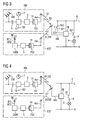
- Figure 4 represents a system similar to the system of Figure 3 , but wherein hardwired switching element SE2 has been eliminated, since this function has been taken over by wireless switch FSD.
- the embodiment of Figure 4 is particularly preferable for an installation in which a hardwired switching element SE2 would require considerable installation expense, since installation costs can thereby be saved without impairing the functionality of the overall system.
- FIG. 5 shows radio receiver FE and its subcomponents in a schematic representation.
- Radio receiver FE is coupled to energy source E directly, so that a power supply unit PU converts the electrical energy input via the connected alternating current into a DC voltage suitable for the electronic components of radio receiver FE. That is to say, a radio module F of the radio receiver, as well as a control unit STE and switching element SE1 are supplied with electrical energy by power supply unit PU.
- An antenna Ant with which the received radio signals are passed on to radio module F, is coupled to radio module F.
- Radio module F demodulates the radio signals, separates the carrier frequencies from the signals S1 or S2 that are actually to be transmitted, and relays signals S1 or S2 to control unit STE.
- Control unit STE evaluates the input signals S1 or S2 and transmits a switching signal to first switching element SE1.
- Switching element SE1 may be a reed contact or a relay contact.
- one side of the contact is coupled to the phase conductor of the power supply network, and the electrical load is connected to the other side of the contact. If the contact closes, the potential of the phase conductor is connected to the load.
- the electrical load which is connected at output A and is coupled to the neutral conductor of the power supply network, has the electrical energy provided by the power supply network available to it when the contact is closed.
- FIG. 6 shows an additional embodiment of the system with presence detector BM and radio receiver FE.
- radio receiver FE is connected to electrical energy source E.
- the electrical energy source E is formed in this embodiment and the subsequent ones as well by a power supply network from a 220-230 VAC network.
- a phase conductor L and a neutral conductor N are provided there. There is a potential difference between these two conductors.
- Electrical load V can be coupled to energy source E by means of terminal A, which can be connected by radio receiver FE to the potential of phase conductor L.
- This takes place by means of radio receiver FE and first switching element SE1 coupled to it, which is coupled to electrical energy source E.
- first switching element SE1 is connected to phase conductor L of electrical energy source E.
- First switching element SE1 is coupled to radio receiver FE in such a way that first switching element SE1 is opened or closed by radio receiver FE.
- the radio receiver has an antenna ANT, with which it receives radio signals and these are supplied to it.
- the radio receiver itself is likewise connected to energy source E between phase conductor and neutral conductors L and N, respectively.
- Radio receiver FE in this embodiment comprises a timing element, or is coupled to the timing element. The timing element determines the duration of time that has elapsed since the last reception, and transmits a switching signal after a predeterminable time period has passed.
- Presence detector BM is arranged at an installation site remote from the radio receiver. Presence detector BM is supplied with its own energy by means of a storage element 3. The presence detector is thus independent of a hardwired energy source. Storage element 3 is coupled to an energy converter that converts physical environmental conditions into electrical energy. Such an energy converter is formed in the illustration by the schematically represented solar module SM. These may be solar cells, for instance, which convert light into electrical energy. The electrical energy thereby obtained is supplied to storage element 3. The electrical energy of storage element 3 is available by means of an electrical connection between storage element 3 and detector circuit 12 to detector circuit 12 for its operation. Detector circuit 12 is constructed to supply the additional components of presence detector BM with energy. Thus, presence sensor BS, a control circuit and a first radio transmitter FS1 and a connected antenna are connected to the detector circuit. A transmission antenna Ant is connected to the first radio transmitter. The frequency-determining component of the radio transmitter is a surface wave resonator 14.
- Presence sensor BS is constructed as an infrared sensor, for example, so that the presence of a person inside the range of presence sensor BS is communicated by an electrical signal to the detector unit. With an appropriate adjustment and calibration of the infrared sensor, it is thus possible to sense the presence of a person even if he is moving only a little or not at all.
- Detector circuit 12 of presence detector BM evaluates this signal and passes it on to control circuit 5, which is supplied with energy by detector circuit 12 only if presence sensor BS has detected a presence.
- Control circuit 5 thus begins to convert the information of presence sensor BS into a signal that is emitted by radio transmitter FS1 via an antenna. If the presence detector senses a presence in the area, then a first predeterminable signal S1 is transmitted.
- an energy-autonomous presence detector BM which transmits the first predeterminable signal S1 depending on the presence of a person.
- the transmitted first predeterminable signal S1 is received by radio receiver FE by the latter's antenna ANT.
- Radio receiver FE evaluates the received signals and determines from them, or recognizes from them, that a signal S1 was received. If radio receiver FE receives first predeterminable signal S1, then switching element SE1 is closed by radio receiver FE and thus the potential of phase conductor L is connected to output A for connecting load V to energy source E.
- the load which is arranged between terminal A and neutral conductor N, then has electrical energy available.
- the timing element that is coupled to radio receiver FE is reset with each received first predeterminable signal S1 to the "starting value” and begins to run for determined time period t. This repeats with each received predeterminable signal S1. Only after the lapse of the entire predeterminable time period t up to a "final value” does the timing element issue a signal to radio receiver FE, which, by means of this information, performs a decoupling of electrical energy source E from terminal A and thus also from electrical load V.
- FIG. 6 The arrangement of individual subcomponents of the system with respect to one another is schematically shown in Figure 6 .
- An installation can be arranged as follows, for example.
- the radio receiver is arranged in a wall receptacle, in which there is a direct connection of phase and neutral lines.
- the electrical load a lighting unit, for example, is arranged on a room ceiling, and is connected to output A and the neutral conductor.
- the presence detector is arranged remotely therefrom, on a wall opposite one of the room doors, for instance, and covers the entire space with its range. If a person enters the room through the room doors, then the light on the room ceiling turns itself on according to the principle described above. After the person leaves the room, a presence can no longer be determined.
- the timing element begins to run over the predeterminable time period. If the time period has elapsed, the lighting unit is shut off.
- the selection of the installation site for the presence detector is ideally guided by its range and the space to be monitored. Due to the energy-autonomous design of the presence detector, it can be installed independently of an existing electrical installation.
- FIG 7 shows the system arrangement already described in Figure 6 , wherein, in contrast to the embodiment shown in Figure 1 , a possibility for turning the electrical load on and off and a second electromechanical switching element SE2 are provided as an alternative in the embodiment of Figure 7 .
- Switching element SE2 is connected in this embodiment to phase conductor L and is constructed as a normally open contact.
- the potential of phase conductor L is thus applied with the second electromechanical switch to the provided input E of the radio receiver.
- the radio receiver is constructed such that, with respect to output A, a phase potential present at the aforementioned input E is equated with a predeterminable signal S1.
- This incoming phase potential in the radio receiver leads to the same evaluation results as a received first predeterminable signal S1. This has the result, as already described above, that the radio receiver couples the load to the electrical energy source by means of first switching element SE1.
- the advantage is that the electrical load can be turned on when a room is entered and can be again turned off when the room is vacated. If the actuation of switching element SE2 is overlooked when the room is vacated, however, the timing element of the presence detector causes the light to be turned off automatically after the lapse of the predeterminable time period t. After the lapse of the predeterminable time period t, radio receiver FE decouples terminal A, and thus load V as well, from electrical energy source E.
- An alternative embodiment of the above-described embodiment of second electromechanical switching element SE2 is a momentary contact switch.
- input E receives the potential of phase conductor L only for the duration of the keypress for each switching process.
- This short switching pulse is evaluated at radio receiver FE as a function of the state at output A. That is to say, each switching pulse at input E brings about a change of state in output A. If output A is at zero potential, then a switching pulse at input E causes a connection of the potential of phase conductor L to electrical load V.
- FIG 8 shows an additional embodiment which is expanded with respect to the embodiment from Figure 6 , as well as the embodiment from Figure 7 , in that an energy-autonomous wireless switch FST is added.
- the energy-autonomous wireless switch FST is constructed such that when a force F is exerted on an actuating element BE, an electromechanical energy transformer EMW is likewise actuated.
- the input force F is converted at least to a predetermined extent into electrical energy by a mechanical coupling of actuating element BE to electromechanical energy transformer EMW.
- a first or a second predeterminable signal S1 or S2, respectively, is transmitted by means of this electrical energy.
- the wireless switch comprises at least one control circuit 5 for this purpose, which is likewise operated with this electrical energy.
- At least one first and one second actuation sensor BT1 and BT2 are connected to this control circuit 5.
- the first or the second actuation sensor BT1 or BT2 is excited, depending on the actuation direction of actuating element BE.
- the actuation direction is determined in this way. If first actuation sensor BT1 is excited, then first predeterminable signal S1 is transmitted. If second actuation sensor BT2 is excited, then second predeterminable signal S2 is transmitted.
- the wireless switch is similar to a toggle switch with a rocker.
- the rocker comprises a first switching direction for "on” and a second switching direction for "off.”
- the actuation sensors each detect the switching direction so that downstream control circuit 5 passes on this information by means of the actuation sensor to second radio transmitter FS2.
- Second radio transmitter FS2 transmits this information by means of a radio signal to an antenna ANT coupled to second radio transmitter FS2.
- Simple momentary contact switches which make the corresponding information available to the control circuit by means of a closed contact, are suitable as actuation sensors.
- the contact switches themselves are energy-free or potential-free switching elements.
- a surface wave resonator 14 is provided as a frequency-determining element in the second radio transmitter.
- the wireless switch offers the advantage of being arranged or installed at an arbitrary site in a space, independently of an existing electrical installation.
- Surface wave resonator 14 can be as the presence detector constructed in the same way. A distinction of the carrier frequencies at radio receiver FE to determine whether the received signal was transmitted from presence detector BM or wireless switch FST is not necessary.
- Figure 8 thus comprises a variety of possibilities for coupling a load to an energy source or for controlling the coupling of the energy source, and for decoupling the load from the energy source in case of a predeterminable time period without a presence.
- Figure 9 represents a system similar to the system of Figure 8 , but wherein hardwired switching element SE2 has been eliminated, since this function has been taken over by wireless switch FSD.
- the embodiment of Figure 9 is particularly preferable for an installation in which a hardwired switching element SE2 would require considerable installation expense, since installation costs can thereby be saved without impairing the functionality of the overall system.
- Radio receiver FE shows radio receiver FE and its subcomponents in a schematic representation.
- Radio receiver FE is coupled directly to energy source E, so that a power supply unit PU converts the electrical energy input via the connected alternating current into a DC voltage suitable for the electronic components of radio receiver FE. That is to say, a radio module F of the radio receiver, as well as a control unit STE, a timing element T and a switching element SE1 are supplied with electrical energy by power supply unit PU.
- An antenna Ant with which the received radio signals are passed on to radio module F, is coupled to radio module F.
- Radio module F demodulates the radio signals, separates the carrier frequencies from the signal S1 that is actually to be transmitted, and relays signal S1 to control unit STE.
- Control unit STE evaluates the input signal S1 and transmits a switching signal to first switching element SE1.
- Switching element SE1 may be a reed contact or a comparable relay contact.
- one side of the contact is coupled to the phase conductor of the power supply network, and the electrical load is connected to the other side of the contact. If the contact closes, the potential of the phase conductor is connected to the load.
- the electrical load which is connected at output A and is coupled to the neutral conductor of the power supply network, has the electrical energy provided by the power supply network available to it when the contact is closed.
- FIG 11 shows a schematic process sequence with the above-described embodiment, in which the timing element is coupled to the radio receiver.
- the process begins at an arbitrary time point, at which a presence 110 is sensed by means of the presence detector. This event triggers an internal process at the presence detector, at the end of which a first predeterminable radio signal S1 is transmitted.
- the radio signal is received by the radio receiver.
- Reception 130 of the radio signal triggers an internal process at the radio receiver, which essentially comprises the coupling 150 of output A to energy source E, and in parallel therewith, the resetting of the timing element to a "starting value" 140.
- the timing element now begins to run for a predeterminable time period, until either the time point "final value” is reached or the timing element is reset to the "starting value” by another reception 130 of the first predeterminable radio signal. If the time point "final value” is reached, an internal process begins at the radio receiver, at the end of which the electrical energy source is decoupled from terminal A, and thus also from electrical load V.
- FIG 12 shows a schematic process sequence with the above-described embodiment, in which the timing element is coupled to the presence detector.
- the process begins at an arbitrary time point, at which a presence 110 is sensed by means of presence detector BM. This event triggers an internal process at presence detector BM, at the end of which a first predeterminable radio signal S1 is transmitted on the one hand, and the timing element is reset to a "starting value" 140 on the other.
- the timing element now begins to run for a predeterminable time period, or to count the lapsed time, until either the time point "final value” is reached, or until a presence is again sensed and the timing element is reset repeatedly to the "starting value.”
- the radio signal is received by the radio receiver.
- the reception 130 of radio signal S1 triggers an internal process at the radio receiver that comprises the coupling 150 of output A to energy source E.
- the timing element continues to run at presence detector BM and reaches the "final value" 160.
Landscapes
- Engineering & Computer Science (AREA)
- Computer Networks & Wireless Communication (AREA)
- Physics & Mathematics (AREA)
- General Physics & Mathematics (AREA)
- Automation & Control Theory (AREA)
- Selective Calling Equipment (AREA)
- Keying Circuit Devices (AREA)
- Transmitters (AREA)
- Arrangements For Transmission Of Measured Signals (AREA)
- Geophysics And Detection Of Objects (AREA)
Description
- The invention relates to a system and a method with at least one presence detector, wherein the presence detector has a radio transmitter. The system further comprises at least one radio receiver, which is constructed to be able to receive and evaluate signals of the presence detector that are transmitted via radio. The radio receiver further comprises at least one device that acts on downstream devices as a function of the evaluation. For instance, a switching element turns an electrical load, such as a lighting unit, on and off, i.e., couples it to and decouples it from a source of power. The invention further relates to a presence detector that detects the presence of a person inside a space or an area, or senses and reports it. The invention further relates to a radio receiver that is constructed to couple an electrical terminal to a source of electrical energy, and thus supply an electrical load connected to the terminal with electrical energy.
- Electrical loads such as lighting units and other electrically operated apparatuses are connected to the public power supply network, for example, which can be a 50-60 Hz, 220-230 VAC network. The electrical loads are generally turned on and off by electromechanical switching elements or are completely coupled to or decoupled from the energy supply formed by the electric power network. The switching loads in these cases are frequently part of the electrical installations in the house. It is possible to perform the switching process with a wirelessly transmitted command by means of a radio receiver and the corresponding radio transmitter. It is additionally possible, as shown in the document
DE 10309334 , to provide an energy-autonomous movement detector. The latter is activated, for instance, by a movement of a person inside its area of effect and is supplied with energy. With this energy, the radio receiver transmits a radio signal. The transmitted radio signal can be received by all the radio receivers in the vicinity that are associated with the radio transmitter, and can be evaluated specifically at each receiver. After the evaluation, the radio receiver passes data signals to addressable receiver systems that are coupled to the radio receiver. These in turn perform an action such as switching on a lighting unit or an electrical load. Thus the lighting unit is turned on as a result of the detected motion and requires or uses electrical energy. Switching elements that allow a user to turn off the electrical load or decouple it from the source of electrical energy are provided for shutting off the lighting unit. The user may be distracted by other things, forget to separate the electrical load from the energy source by switching it off, and it will then unnecessarily consume electric power or electrical energy until another user notices it. - It is consequently the object of the invention to automatically decouple unneeded electrical loads from the power network and from the energy source.
- It is provided a System with a presence detector comprising a presence sensor, a timing element and a first radio transmitter, wherein presence detector is constructed to transmit at least first one predeterminable signal or one second predeterminable signal by means of first radio transmitter, and wherein presence sensor is coupled to first radio transmitter), and presence sensor triggers the sending of first signal after a sensed presence,and wherein, after the lapse of a predetermined time period after the time point of the last sensed presence, second predeterminable signal is transmitted, a terminal for an electrical load, a radio receiver, which is constructed to couple terminal by means of a switching element energy source if second predeterminable signal is received wherein energy for operating the presence detector and its components is supplied from the energy available from the environment, and wherein a wireless switch is provided that is constructed to transmit wirelessly and energy-autonomously at least one first predeterminable signal or one second predeterminable signal by means of a second radio transmitter.
- Furthermore it is provided that the energy for operating the presence detector and its components is supplied by a photoelectric energy converter, that a radio receiver is coupled to a hardwired electromechanical switching element in such a way that a first switch position of switching element at radio receiver generates an input signal that excites the radio receiver to couple electrical load to electrical energy source by means of switching element, and a second switch position (ST2) disconnects the input signal from the radio receiver, so that electrical load is decoupled from the electrical energy source. Furthermore it is provided that radio receiver is coupled to a hardwired electromechanical switching element, which is constructed as a momentary contact switch, in such a way that a first switching pulse of switching element at radio receiver generates an input signal that excites the radio receiver to couple electrical load to electrical energy source by means of switching element, and a second switching pulse excites the radio receiver to disconnect electrical load from electrical energy source, by means of switching element. Furthermore it is provided that a wireless switch is provided that is constructed to transmit wirelessly and energy-autonomously at least one first predeterminable signal or one second predeterminable signal by means of a second radio transmitter. Furthermore it is provided that a wireless switch comprises an actuating element which is coupled to an electromechanical energy converter in such a way that a mechanical force exerted on actuating element is converted at energy converter into electrical energy, wherein the electrical energy is conducted to second radio transmitter.
- Furthermore it provided that a wireless switch comprises a first actuation sensor that senses an actuation of actuating element in a first direction, and a second actuation sensor that senses an actuation of actuating element in a second direction.
- Furthermore it is provided that a first predeterminable signal is transmitted in case of a response of first actuation sensor, or a second predeterminable signal is transmitted in case of a response of second actuation sensor. Furthermore it is provided that a presence detector comprises at least a storage element for storing electrical energy, a control unit for encoding the detected presence, a detector circuit that activates control circuit in the presence of a predeterminable electrical signal at presence sensor and deactivates it after the decay of the electrical signal, a photovoltaic element to which storage element is connected for supplying power to presence detector.
- Furthermore it is provided that a detector circuit is operated in a pulsed mode, wherein an off-phase is longer than an on-phase, that a storage element is a capacitor and/or an electrochemical energy accumulator, that presence sensor is implemented as an infrared sensor, that the infrared sensor is equipped with a lens for concentrating the infrared radiation fields.
- It is provided a System with a presence detector comprising a presence sensor and a first radio transmitter, wherein presence detector is constructed to send at least one first predeterminable signal by means of first radio transmitter, and wherein presence sensor is coupled to first radio transmitter, and presence sensor triggers the transmitting of first signal after a sensed presence, a terminal for an electrical load, a radio receiver with a timing element, which is constructed to couple terminal by means of switching element to electrical energy source if first predeterminable signal is received, and which is constructed to decouple terminal by means of switching element from the electrical energy source after the lapse of a predeterminable time period after the time point of the last reception of first predeterminable signal, wherein energy for operating the presence detector and its components is supplied from the energy available from the environment, and wherein a wireless switch is provided that is constructed to transmit wirelessly and energy-autonomously at least one first predeterminable signal or one second predeterminable signal by means of a second radio transmitter.
- Furthermore it is provided that the energy for operating the presence detector and its components is supplied by a photoelectric energy converter, that a radio receiver is coupled to a hardwired electromechanical switching element in such a way that a first switch position of switching element at radio receiver generates an input signal that excites the radio receiver to couple electrical load by means of switching element to electrical energy source), and a second switch position disconnects the input signal from the radio receiver so that electrical load is decoupled from the electrical energy source.
- Furthermore it is provided that a radio receiver is coupled to a hardwired electromechanical switching element, which is constructed as a momentary contact switch, in such a way that a first switching pulse at radio receiver causes electrical load to be coupled to electrical energy source (E) by means of switching element and a second switching pulse causes electrical load to be decoupled from electrical energy source and that a wireless switch is provided that is constructed to transmit, wirelessly and energy-autonomously, at least one first predeterminable signal or one second predeterminable signal by means of a second radio transmitter.
Furthermore it is provided that a wireless switch comprises an actuating element that is coupled to an electromechanical energy converter in such a way that a mechanical force exerted on actuating element is converted at energy converter into electrical energy, wherein the electrical energy is conducted to second radio transmitter. - Furthermore it is provided that a wireless switch comprises a first actuation sensor that senses an actuation of actuating element in a first direction, and a second actuation sensor that senses an actuation of actuating element in a second direction, that a first predeterminable signal is transmitted in case of a response of first actuation sensor.
- Furthermore it is provided that a presence detector comprises at least a storage element restoring electrical energy, a control unit for encoding the detected presence, a detector circuit that activates control circuit in the presence of a predeterminable electrical signal at presence sensor and deactivates it after the decay of the electrical signal, a photovoltaic element to which storage element is connected for supplying energy to presence detector, that a detector circuit is operated in a pulsed mode, wherein an off-phase is longer than an on-phase and that a storage element is a capacitor and/or an electrochemical energy accumulator.
- Furthermore it is provided that a presence sensor is implemented as an infrared sensor, that the infrared sensor is equipped with a lens for concentrating the infrared radiation fields.
- It is provided a method with a presence detector in which a first predeterminable signal is transmitted after a sensed presence, wherein a terminal for an electrical load is coupled by a radio receiver (FE) to an electrical energy source by means of a switching element when the first predeterminable signal is received and wherein after the lapse of a predetermined time period following the time of the last reception of first predeterminable signal, terminal is decoupled by means of switching element from the electrical energy source wherein that energy for operating the presence detector and its components is supplied from the energy available from the environment, and wherein at least one first predeterminable signal or one second predeterminable signal is provided energy-autonomously by a wireless switch.
- It is provided a method with a presence detector in which a first predeterminable signal is transmitted after a sensed presence, and wherein a second predeterminable signal is transmitted after the lapse of a predetermined time period following the last sensed presence, a terminal for an electrical load is coupled by a radio receiver to an electrical energy source by means of a switching element when first predeterminable signal is received and wherein terminal is decoupled from the electrical energy source by means of switching element after reception of second predeterminable signal wherein that energy for operating the presence detector and its components is supplied from the energy available from the environment, and wherein at least one first predeterminable signal or one second predeterminable signal is provided energy-autonomously by a wireless switch.
- It is provided a presence detector comprising a presence sensor, a timing element and a first radio transmitter, wherein presence detector is constructed to transmit at least first one predeterminable signal or one second predeterminable signal by means of first radio transmitter, and wherein presence sensor is coupled to first radio transmitter, and presence sensor triggers the sending of first signal after a sensed presence, and wherein, after the lapse of a predeterminable time period after the time point of the last sensed presence, second predeterminable signal is transmitted.
- Furthermore it is provided that the presence detector comprises at least a storage element for storing electrical energy, a control unit for encoding the detected presence, a detector circuit that activates control circuit in the presence of a predeterminable electrical signal at presence sensor and deactivates it after the decay of the electrical signal, a photovoltaic element to which storage element is connected for supplying power to presence detector, wherein photovoltaic element is dimensioned smaller than is required for a direct operation of presence detector.
- Furthermore it is provided that the detector circuit is operated in a pulsed mode, wherein an off-phase is longer than an on-phase, that the storage element is a capacitor and/or an electrochemical energy accumulator, that a presence sensor is implemented as an infrared sensor, that the infrared sensor is equipped with a lens for concentrating the infrared radiation fields and that the first and/or second radio transmitter (FS1/FS2) has a very short settling time.
- Furthermore it is provided that
a surface wave resonator is the frequency-determining component of first radio transmitter and that a first radio transmitter transmits with a high bandwidth. - It is provided a radio receiver with a timing element, which receiver is constructed to couple terminal by means of a switching element to an electrical energy source if first predeterminable signal is received, and which is constructed to decouple terminal by means of switching element from the electrical energy source after the lapse of a predetermined time period following the last reception of first predeterminable signal.
- Furthermore it is provided that the radio receiver is coupled to a hardwired electromechanical switching element in such a way that a first switch position of switching element at radio receiver generates an input signal that excites the radio receiver to couple terminal to electrical energy source by means of switching element, and a second switch position disconnects the input signal from the radio receiver, so that terminal is decoupled from the electrical energy source.
- Furthermore it is provided that the radio receiver
is coupled to a hardwired electromechanical switching element, which is constructed as a momentary contact switch, in such a way that a first switching pulse of switching element generates an input signal at radio receiver that excites the radio receiver to couple terminal by means of switching element to electrical energy source, and a second switching pulse excites the radio receiver to disconnect terminal from the electrical energy source. - The system and the method will be described in detail below. The motion detector and the radio receiver will then be described in detail.
- Thus a system that comprises the components described in detail below is proposed. The system accordingly comprises at least one presence detector, at least one electrical terminal for an electrical load and at least one radio receiver. The presence detector is constructed to transmit at least first one predeterminable signal or at least one second predeterminable signal by means of the first radio transmitter. These signals can be predetermined by means of a device that allows a user or a skilled person to select various signals while setting up the presence detector, or during the initial installation of the system. It is thus possible to achieve an unambiguous association of presence detector and radio transmitter within radio range.
- A presence detector is a device that is constructed to determine the presence of persons in an observation area. This definition comprises not only a motion, but also can also comprise a nonmoving or very slowly moving person. The presence detector achieves this by means of a presence sensor, which is constructed for instance as an infrared sensor, in particular, a passive infrared sensor (PIR). An infrared sensor converts infrared radiation or heat radiation, into an electrical signal. Such a passive infrared sensor is particularly suited for detecting a moving person. A timing element is, for example, an electronic clock or an electrical capacitor that has a predeterminable discharge time when coupled to an electrical resistor. A radio transmitter is an electronic circuit arrangement or an electrical device that transmits analog or digital signals containing information or data by means of wireless transfer. For example, a radio transmitter modulates the signals to be transmitted onto a so-called carrier signal. The carrier signal, high-frequency electromagnetic waves for example, wirelessly transports the signal to be transferred to a remote location. At the remote location, there is a radio receiver that separates the signal to be transmitted from the carrier signal and supplies it for further processing.
- The presence sensor of the presence detector is connected to the first radio transmitter and, after presence has been sensed, initiates, by means of an initiation signal to the first radio transmitter, the transmission of the first signal. A sensed presence is understood to mean the presence of a person or a relatively large animal in the space to be monitored. Adjustment possibilities, with which the sensitivity and/or the response behavior of the presence sensor can be adjusted, are provided on the presence detector. The first signal is sent again at each response of the presence sensor. If there is not another response of the presence sensor over a predeterminable time period after the transmission of the first predeterminable signal, then there is a transmission of a second predeterminable signal. The predeterminable time period is adjustable even after installation of the system. An adjustment possibility, which is designed to be easily accessible, is provided for this purpose on the presence detector. It may be provided, for instance, by a rotary potentiometer. The first and the second predeterminable signals differ from one another. The signal can be provided, for example, by a short pulse of identical duration, which is transmitted at two different frequencies for differentiation. Or the two signals can be distinguished from one another by the signal duration or a pulse sequence.
- The radio receiver is constructed to couple an electrical energy source to or decouple it from an electrical load by means of a switching element. If the radio receiver receives the first predeterminable signal, the electrical load is coupled by means of the switching element to the electrical energy source, if the radio receiver receives the second predeterminable signal, the electrical load is decoupled from the electrical energy source.
- This solution combines more than one advantage. First, the electrical load is coupled to the energy source by a sensed presence, and is thus in operation or at least ready for operation, since it is coupled or connected to the energy source. Second, the electrical load is automatically disconnected from the energy supply if no presence can be determined over a predeterminable time.
- A possibility of turning the load on and off by means of a manually operated switch is provided in one refinement of the system as an additional possibility for turning the load on and off. A hardwired electromechanical switching element, having two switch positions, open or closed, is also provided. This can be a toggle switch, for example, the first switch position of which means "on" and the second switch position of which means "off." Such a toggle switch is thus formed by an electromechanical switching element with a make-and-break contact. This electromagnetic switching element is connected to the radio receiver and connects the line potential, 220-230 V, for example, to a specially provided voltage input on the radio receiver. The input is designed such that if a predetermined voltage level such as a line voltage of 230 VAC is present at this input, it is evaluated by the radio receiver the same as the reception of the first predeterminable signal. A decrease in the line voltage is then evaluated by the radio receiver like the reception of the second predeterminable signal. Thus the electrical load is connected to or disconnected from the electrical energy source by the hardwired switching element or the manually operated switch.
- The hardwired electromagnetic switching element can be used in principle in two different embodiments; as a momentary contact switch in one embodiment, or as a rocker switch in the other embodiment. Only short switching pulses are transmitted in the embodiment as a momentary contact switch. The input at the radio receiver is constructed, in comparison with the preceding example, such that a short switching pulse is interpreted as the first or the second radio signal. This depends on the momentary switch position of the switching element that couples the load to the electrical energy source. That is to say, each switching pulse at the input brings about a change of state at the output. If the output is at zero voltage, then a switching pulse at the input brings about a connection of the potential at the given phase conductor to the electrical load.
- Alternatively to being connected to the line voltage, the switch can also be set up to be potential-free, and merely coupled to the radio receiver that evaluates the switch position of the contact, open or closed. For instance, the closed switch position would be evaluated as a first predeterminable radio signal, and an open switch position as a second predeterminable signal.
- If the electrical load in the system is turned on by means of the switch and there is no determined presence in the area monitored by the presence detector after a relatively long time, or until the lapse of the predeterminable time period, then the presence detector transmits the second predeterminable signal to the radio receiver. At the radio receiver, this brings about a signal to the first switching element, whereupon the electrical load is decoupled from the electrical source. For this purpose, the presence detector always transmits the second predeterminable signal at a predetermined time interval following the last sensed presence, and thus effects a shutoff of the load whenever no presence in the area of the presence sensor was detectable over the duration of a predetermined time period. Independently of the manner in which the load was coupled to the energy source, it is thus decoupled from the energy source. It is advantageous in the embodiment with a hardwired switching element that, independently of how the electric power network or the energy source is coupled to the electrical load, whether this happened due to the presence detector or the switch, the presence detector causes the radio receiver to disconnect the load from the electrical energy source, the electric power network, after a predetermined time.
- Alternatively or in combination with the previous possibility of a hardwired switch, a refinement of the system provides the possibility of transmitting a first predeterminable signal to the radio receiver by means of a wireless switch as well, thus likewise bringing about a coupling of the energy source to the electrical load. A wireless switch offers the particular advantage of being placed at an arbitrary site without additional installation, easily and without the considerable expense of installation. One need only take into account the range of the radio signal transmitted by the wireless switch.
- For the above purpose, the wireless switch has an actuation element and an electromagnetic energy converter, the energy converter being coupled to the actuation element, and input mechanical force being converted into electrical energy. To carry out a switching process, an input of mechanical force onto the actuation element is necessary in any case. The electrical energy generated in this way is supplied to a second radio transmitter that is integrated into the wireless switch. The wireless switch thereby sends the first predeterminable signal. This signal is received and evaluated by the radio receiver.
- It is advantageous to construct the wireless switch such that it also comprises at least one actuation sensor. The wireless switch preferably comprises a first and a second actuation sensor with which a respective first or second actuation direction is detected. The respective first or second predeterminable signal is transmitted, depending on which actuation direction was detected. It is thus assured that at least two different signals can be sent to the radio receiver, with these again bringing about at the radio receiver either a coupling of the load to the energy source or a decoupling of the load. These signals correspond to the first or second predeterminable signal, respectively.
- It is advantageous to design the presence detector to be energy-autonomous, i.e., the presence detector is independent of a hardwired electrical energy supply. The energy for operating the presence detector and its components is supplied from the energy available from the environment, so that no battery is necessary for operation. The components of the presence detector include, for instance, a detector circuit, a presence sensor connected to it and the radio transmitter. The energy supply is formed, for instance, by a photoelectric energy converter such as one or more solar cells. In view of the savings of energy then available in the presence detector in this case, the detector circuit must be specially designed for extremely low-power operation. This is the only component of the presence detector that must always be supplied with energy. Even the timing element is not supplied with energy all the time, but only for the duration of the predeterminable time period until the second predeterminable signal is sent. With this signal, all unneeded components of the presence detector are shut off. The presence sensor, which must likewise be supplied with energy, is connected to the detector circuit. In order to save energy with the presence sensor, an operating mode of the detector circuit is proposed that provides on-phases and off-phases over time for the detector circuit, the off-phases being chosen with respect to the on-phases such that a high duty ratio between on-phases and off-phases results. Thereby optimally long operating periods of the presence detector can be realized even in dark phases, i.e., in phases in which no energy supply from light or other environmental energy is possible.
- An energy-autonomous motion detector is operated by electrical energy that is obtained by converting so-called environmental energy into electrical energy. Environmental energy is understood to mean forms of energy such as heat, motion or other forms of energy that can be converted by means of converter elements into electrical energy. These include, for example, thermoelectric elements, piezoelectric elements, photovoltaic elements, Seebeck elements, pyroelectric elements, or other elements that transform physical values into separated electrical charges.
- In order to increase transmission security, the radio signals of the presence detector or the wireless switch are transmitted with a large bandwidth and/or in a temporal sequence.
- The system described below differs from the aforementioned system in, among other things, the arrangement of the timing element on/in the radio receiver, whereas the timing element in the above-described system is arranged on/in the presence detector. Two additional distinguishing features result from this difference. The arrangement of the timing element on/in the radio receiver hence does not require any transmission of the second predeterminable signal from the presence detector to the radio receiver. This results from the fact that the decoupling of the electrical energy source from the terminal for the electrical load is initiated by the reaching of a temporal endpoint of the timing element.
- A system is additionally proposed which likewise solves the problem, but differs from those described above in regard to certain characteristics, and comprises characteristics that will be described below. The system thus likewise comprises at least one presence detector, at least one electrical terminal for an electrical load and at least one radio receiver. The presence detector itself comprises at least one presence sensor and at least one first radio transmitter, the presence detector being constructed to transmit at least one first predeterminable signal by means of the first radio transmitter. This signal can be predetermined by means of a device, whereby it is possible to select from various signals during the setup of the presence detector or the initial installation of the system. It is thus possible to produce a clear and unambiguous association of presence detector and radio receiver inside the radio range of the presence detector.
- The presence sensor of the presence detector is connected to the first radio transmitter, and, by means of an initiation signal to the first radio transmitter, effects the transmission of the first signal after a presence is sensed. A sensed presence is to be understood as the presence of a person or a relatively large animal in the space to be monitored. Adjustment possibilities, with which the sensitivity and/or the response behavior of the presence sensor is/are adjustable, are provided on the presence detector.
- The radio receiver is constructed to couple an electrical terminal for an electrical load to an electrical energy source by means of a switching element, or to decouple it. If the radio receiver receives the first predeterminable signal, the electrical load is coupled by means of a switching element to the electrical energy source. The radio receiver comprises a timing element. After the lapse of a predeterminable time period following the time of the last reception of the first predeterminable signal, the radio receiver decouples the electrical terminal from the electrical energy source.
- This solution combines more than one advantage. First, the electrical load is coupled to the energy source by a sensed presence, and is thus in operation or at least ready for operation since it is coupled or connected to the energy source. Second, the electrical load is disconnected from the energy supply if no presence can be detected over a predeterminable time. Energy savings for the position detector are also achievable, since the timing element in this system is arranged on the radio receiver. The timing element thus does not burden the scarce energy resources at the position detector. With respect to the above-described system, the motion detector is additionally relieved of the burden of transmitting the second predeterminable signal.
- The possibility of turning the load on and off by means of a manually operated switch is provided in a refinement of the system as an additional possibility for turning the load on and off. Here a hardwired electromechanical switching element is provided that has two switch positions, open or closed. This can be a toggle switch, for example, the first switch position of which is "on" and the second switch position of which is "off." Such a toggle switch is thus formed by an electromechanical switching element with a make-and-break contact. This electromagnetic switching element is connected to the radio receiver and switches, for instance, the line potential, 220-230 V for example, to a specially provided voltage input on the radio receiver. The input is designed such that if a predetermined voltage level such as a line voltage of 230 VAC is present at this input, it is evaluated by the radio receiver the same as the reception of the first predeterminable signal. Thus a predeterminable time begins to run at the timing element; after the lapse of the predeterminable time, the radio receiver decouples the electrical terminal from the electrical energy source. This process is interrupted by a reception of the first predeterminable signal and starts over.
- The hardwired electromagnetic switching element can be used in principle in two different embodiments: as a momentary contact switch in one embodiment, or as a rocker switch in the other embodiment. Only short switching pulses are transmitted in the embodiment as a momentary contact switch. The input at the radio receiver is constructed, in comparison with the preceding example, such that a short switching pulse is interpreted as the first or the second radio signal. This depends on the momentary switch position of the switching element that couples the load to the electrical energy source. Alternatively to being connected to the line voltage, the switch can also be set up to be potential-free, and merely coupled to the radio receiver that evaluates the switch position of the contact, open or closed.
- If the electrical load in the system is turned on by means of the switch and there is no reaction of the presence sensor in the area monitored by the presence detector after a relatively long time, or until the lapse of the predeterminable time period, then the radio receiver supplies a signal to the first switching element, whereupon the electrical load is decoupled from the electrical source. The radio receiver performs a disconnection of the electrical load from the electrical energy source at a predetermined time interval following the last sensed presence, i.e., after the last reception of the first predeterminable signal. The time sequence is interrupted by a new reception of the first predeterminable signal and starts over. It is advantageous in the embodiment of the hardwired switching element that, independently of how the electric power network or the energy source is coupled to the electrical load, whether this happened due to the presence detector or the switch, the presence detector has the effect that, after a predetermined time, the radio receiver disconnects the load from the electrical energy source, the electric power network.
- Alternatively or in combination with the possibility of a hardwired switch, a refinement of the system provides the possibility of transmitting a first predeterminable signal to the radio receiver by means of a wireless switch as well, thus likewise bringing about a coupling of the energy source to the electrical load. In particular, a wireless switch offers the advantage of being placed at an arbitrary site without additional installation, easily and without the considerable expense of installation. One need only take into account the range of the radio signal that is transmitted by the wireless switch.
- For the above purpose, the wireless switch has an actuation element and an electromagnetic energy converter, which is coupled to the actuation element, and when a mechanical force is applied to the actuation element, which is necessary in any case for a manually operated switching process, this input mechanical force is converted into electrical energy. The electrical energy thereby generated is supplied to a second radio transmitter that is integrated into the wireless switch. The wireless switch thereby sends the first predeterminable signal. This signal is received and evaluated by the radio receiver.
- It is advantageous to construct the wireless switch such that it also comprises at least one actuation sensor. The wireless switch preferably comprises a first and a second actuation sensor, with which a respective first or second actuation direction is detected. The respective first or second predeterminable signal is transmitted, depending on which actuation direction was detected. It is thus assured that at least two different signals can be sent to the radio receiver, with these again bringing about at the radio receiver either a coupling of the load to the energy source or a decoupling of the load.
- It is advantageous to design the presence detector to be energy-autonomous, i.e., the presence detector is independent of a hardwired electrical energy supply. The energy for operating the presence detector and its components is supplied from the energy available from the environment, so that no battery is necessary for operation. The components of the presence detector include, for instance, a detector circuit, a presence sensor connected to it and the radio transmitter. The energy supply is formed for instance by a photoelectric energy converter such as one or more solar cells. In view of the savings of energy then available at the presence detector in this case, the detector circuit must be specially designed for extremely low-power operation. This is the only component of the presence detector that must always be supplied with energy. Even the timing element is not supplied with energy all the time, but only for the duration of the predeterminable time period until the second predeterminable signal is sent. The presence sensor, which must likewise be supplied with energy, is connected to the detector circuit. In order to save energy with the presence sensor, an operating mode of the detector circuit is proposed that provides on-phases and off-phases of the detector circuit over time, the off-phases being chosen with respect to the on-phases such that a high duty ratio between on-phases and off-phases results. Optimally long operating periods of the presence detector can thereby be realized even in dark phases, i.e., in phases in which no energy supply from light or other environmental energy is possible.
- In order to increase the transmission security, the radio signals of the presence detector or the wireless switch are transmitted with a large bandwidth and/or in a temporal sequence.
- The problem is also solved by means of a presence detector. The presence detector comprises at least one presence sensor and at least one first radio transmitter, the presence detector being constructed to transmit at least one first predeterminable signal or at least one second predeterminable signal by means of the first radio transmitter. These signals can be predetermined by means of a device that allows a user or a skilled person to select various signals while setting up the presence detector, or during the initial installation of the system. It is thus possible to achieve a clear and unambiguous association of presence detector and radio receiver within the radio range of the presence detector.
- The problem is also solved by means of a radio receiver. The radio receiver is constructed to couple an electrical terminal for an electrical load to an electrical energy source by means of a switching element, or to decouple it. If the radio receiver receives a first predeterminable signal the electrical load is coupled by means of the switching element to the electrical energy source. The radio receiver comprises a timing element. After the lapse of a predeterminable time period following the time of the last reception of the first predeterminable signal, the radio receiver decouples the electrical terminal from the electrical energy source. With each newly received first predeterminable radio signal, the timing element is reset and the running of the predeterminable time starts over. That is to say, the electrical terminal is decoupled from the electrical energy source by means of the radio receiver only if no predeterminable radio signal was received past the predeterminable time period.
-
Figure 1 , a system with presence detector, radio receiver and load, -
Figure 2 , a system with presence detector, radio receiver, load and hardwired switch, -
Figure 3 , a system with presence detector, radio receiver, load, hardwired switch and wireless switch, -
Figure 4 , a system with presence detector, radio receiver, load and wireless switch, -
Figure 5 , a schematic representation of the radio receiver and its subcomponents, -
Figure 6 , a system with presence detector, radio receiver and load, -
Figure 7 , a system with presence detector, radio receiver, load and hardwired switch, -
Figure 8 , a system with presence detector, radio receiver, load, hardwired switch and wireless switch, -
Figure 9 , a system with presence detector, radio receiver, load and wireless switch, -
Figure 10 , a schematic representation of the radio receiver and its subcomponents, -
Figure 11 , a process sequence diagram, -
Figure 12 , a process sequence diagram. -
Figure 1 shows an embodiment of the system with a presence detector BM and a radio receiver FE, wherein radio receiver FE is connected to an electrical energy source E. Electrical energy source E in this and also in the additional embodiments is formed by a power supply network of a 220-230 VAC network. A phase conductor L and a neutral conductor N are provided there. There is a potential difference between these conductors L and N. An electrical load V is coupled to energy source E by means of a terminal A, which can be connected by radio receiver FE to the potential of phase line L. This takes place by means of radio receiver FE and a first switching element SE1, which is coupled to electrical energy source E. For this purpose, first switching element SE1 is connected to phase line L of electrical energy source E. First switching element SE1 closes the contact, then phase line L and thus the potential present there is connected to terminal point A and is available to electrical load V. In this switching state, electrical load V is supplied with electrical energy. First switching element SE1 is coupled to radio receiver FE in such a way that first switching element SE1 is opened or closed by radio receiver FE. The radio receiver has an antenna ANT with which radio signals can be received and supplied to the radio receiver. The radio receiver itself is likewise connected to energy source E between phase and neutral lines L and N. - Position detector BM is arranged at an installation site remote from the radio receiver. Position detector BM has its own energy supply by means of a
storage element 3. The position detector is thus independent of a hardwired energy source.Storage element 3 is connected to an energy converter that converts environmental energy into electrical energy. Such an energy converter is formed in the illustration by the schematically represented solar module SM, formed in this embodiment by solar cells, which convert light into electrical energy. The electrical energy thereby obtained is supplied tostorage element 3. By means of an electrical connection betweenstorage element 3 and adetector circuit 12, the electrical energy ofstorage element 3 is available todetector circuit 12 for its operation.Detector circuit 12 is constructed to supply the additional components of presence detector BM with energy. Thus, presence sensor BS, a control circuit and a first radio transmitter FS1 and a connected antenna, as well as a timing element T are connected to the detector circuit. A transmission antenna Ant is connected to the first radio transmitter. The frequency-determining component of the radio transmitter is asurface wave resonator 14. - Presence sensor BS is constructed as an infrared sensor for example, so that the presence of a person inside the range of presence sensor BS is transmitted by an electrical signal to the detection unit. With an appropriate adjustment and calibration of the infrared sensor it is thus possible to sense the presence of a person even if he is moving only a little or not at all.
Detector circuit 12 of presence detector BM evaluates this signal and passes it on to controlcircuit 5, which is supplied with energy bydetector circuit 12 only if presence sensor BS has detected a presence.Control circuit 5 thus begins to convert the information of presence sensor BS into a signal that is emitted by radio transmitter FS1 via an antenna. If the presence detector senses a presence in the area, then a first predeterminable signal S1 is transmitted. - The timing element that is coupled to
detector circuit 12 is additionally reset to "zero" at each detected presence, and restarts the running of the predetermined time period whenever a presence is detected by presence sensor BS. Timing element T runs over a predeterminable time period t, with a signal being transmitted todetector circuit 12 regarding the end of the predeterminable time period after the predeterminable time period t has expired. Triggered by this information,control circuit 5 and the downstream first radio transmitter FS1 withsurface wave resonator 14 and antenna ANT are activated bydetector circuit 12. From the information of the expired time period t,control circuit 5 forms a second predeterminable signal S2, which is emitted via radio transmitter FS1 and the connected antenna ANT. - Thus an energy-autonomous presence detector BM is created that transmits a first predeterminable signal S1 as a function of a presence, or a second predeterminable signal S2 as a function of a time period t in which no presence has taken place. The transmitted first or second predeterminable signal S1 or S2 is received by radio receiver FE via its antenna ANT. Radio receiver FE evaluates the received signals and determines whether a signal S1 or a signal S2 was received.
- If radio receiver FE receives first predeterminable signal S1, then switching element SE1 is closed via radio receiver FE and is thus connected to the output A for connecting load V to energy source E and thus to the potential of phase L. Thus the load, which is arranged between terminal A and neutral conductor N, has electrical energy available. If the radio receiver receives the predeterminable signal S2, then the radio receiver effects an opening of first switching element SE1 and thus a cutoff of electrical energy at terminal A, whereby there is a decoupling of electrical load V from electrical energy source E.
- The arrangement of the individual subcomponents of the system with respect to one another is schematically shown in
Figure 1 . For example, an installation can be arranged as follows. The radio receiver is arranged in a wall socket in which direct incoming phase and neutral lines are provided. The electrical load, a lighting unit, for example, is arranged on a room ceiling and is connected to output A and the neutral conductor. The presence detector is arranged remotely, on a wall opposite the room door, for example, and covers the entire space within its range. If a person enters this space through the room door, then the light on the room ceiling turns on according to the principle described above. After the person leaves the room, a presence can no longer be determined. After a presence has been sensed for the last time, the timing element begins to run for the predeterminable time period. When the time period has elapsed, the lighting unit is turned off. The selection of the installation site for the presence detector depends upon its range and the space to be monitored. Because of the energy-autonomous design of the presence detector, it can be mounted completely independently of any existing energy installation. -
Figure 2 shows the system arrangement already described inFigure 1 , wherein, in comparison with the embodiment described inFigure 1 , a second electromechanical switching element SE2 is additionally provided in the embodiment ofFigure 2 as an alternative possibility for switching the electrical load on and off. Switching element SE2 is connected in this embodiment to phase conductor L and is constructed as a normally open contact. Thus the potential of phase conductor L is applied with the second electromagnetic switching element to an input E of the radio receiver provided for it in the radio receiver. The radio receiver is constructed such that a phase potential present at the aforementioned input E relative to output A is equated with a predeterminable signal S1. This incoming phase potential thus leads to the same evaluation result in the radio receiver as a received first predeterminable signal S1. This has the effect, as already described above, that the radio receiver couples the load to the electrical energy source by means of first switching element SE1. - The advantage here is that the electrical load can be turned on when the space is entered and turned off when it is vacated. If the user forgets to actuate switching element SE2 when leaving the space, then the timing element of the presence detector has the effect that after the lapse of the predeterminable time period t, the light is automatically shut off by the presence detector. After the lapse of the predeterminable time period t, presence detector BM sends the second predeterminable signal S2 to the radio receiver.
- An alternative embodiment of the above-described embodiment of the second electromechanical switching element SE2 is a momentary contact switch. Input E in this embodiment receives the potential of phase conductor L only for the duration of the keypress for each switching process. This short switching pulse is evaluated at radio receiver FE as a function of the state at output A. That is to say, each switching pulse at input E brings about a change of state at output A. If output A is at zero potential, then a switching pulse at input E brings about a connection of the potential of phase conductor L to electrical load V.
-
Figure 3 shows another embodiment, which is expanded with respect to the embodiment fromFigure 1 and also the embodiment fromFigure 2 in that an energy-autonomous wireless switch FST has been added to the system. The energy-autonomous wireless switch FST is constructed in such a way that when a force F is exerted on actuation element BE, an electromechanical energy converter EMW is likewise actuated. Due to a mechanical coupling of actuating element BE to electromechanical energy converter EMW, the input force F is converted at least to a predetermined extent into electrical energy. A first or second predeterminable signal S1 or S2, respectively, is transmitted by means of this electrical energy. For this purpose, the wireless switch comprises at least onecontrol circuit 5, which is likewise operated with this electrical energy. At least one first and one second actuation sensor BT1 or BT2, respectively, is connected to thiscontrol circuit 5. Depending on the actuation direction of actuating element BE, the first or the second actuation sensor BT1 or BT2 is excited. The actuation direction can be determined in that way. If first actuation sensor BT1 is excited, first predeterminable signal S1 is transmitted. If second actuation sensor BT2 is excited, second predeterminable signal S2 is transmitted. Transferred to a practical example, the wireless switch is similar to a toggle switch with a rocker. The rocker comprises a first switching direction for "on" and a second switching direction for "off." The actuation sensors each detect the switching direction so thatdownstream control circuit 5 passes on this information by means of the actuation sensor to the second radio transmitter FS2. Second radio transmitter FS2 transmits this information by means of a radio signal to an antenna ANT coupled to second radio transmitter FS2. Simple momentary contact switches, which make the corresponding information available to the control circuit by means of a closed contact, are suitable as actuation sensors. The contact switches themselves are energy-free or potential-free switching elements. - A
surface wave resonator 14 is provided as a frequency-determining element in the second radio transmitter. The wireless switch offers the advantage of being arranged or installed at an arbitrary site in a space, independently of an existing electrical installation.Surface wave resonator 14 can be of the same construction as that of the presence detector. A distinction of the carrier frequencies at radio receiver FE to decide whether the received signal was transmitted from presence detector BM or wireless switch FST is not necessary. -
Figure 3 thus comprises a variety of possibilities for coupling a load to an energy source or for controlling the coupling of the energy source, and for decoupling the load from the energy source in case of a predeterminable time period without presence. -
Figure 4 represents a system similar to the system ofFigure 3 , but wherein hardwired switching element SE2 has been eliminated, since this function has been taken over by wireless switch FSD. The embodiment ofFigure 4 is particularly preferable for an installation in which a hardwired switching element SE2 would require considerable installation expense, since installation costs can thereby be saved without impairing the functionality of the overall system. -
Figure 5 shows radio receiver FE and its subcomponents in a schematic representation. Radio receiver FE is coupled to energy source E directly, so that a power supply unit PU converts the electrical energy input via the connected alternating current into a DC voltage suitable for the electronic components of radio receiver FE. That is to say, a radio module F of the radio receiver, as well as a control unit STE and switching element SE1 are supplied with electrical energy by power supply unit PU. An antenna Ant, with which the received radio signals are passed on to radio module F, is coupled to radio module F. Radio module F demodulates the radio signals, separates the carrier frequencies from the signals S1 or S2 that are actually to be transmitted, and relays signals S1 or S2 to control unit STE. Control unit STE evaluates the input signals S1 or S2 and transmits a switching signal to first switching element SE1. Switching element SE1 may be a reed contact or a relay contact. In this embodiment, one side of the contact is coupled to the phase conductor of the power supply network, and the electrical load is connected to the other side of the contact. If the contact closes, the potential of the phase conductor is connected to the load. The electrical load, which is connected at output A and is coupled to the neutral conductor of the power supply network, has the electrical energy provided by the power supply network available to it when the contact is closed. -
Figure 6 shows an additional embodiment of the system with presence detector BM and radio receiver FE. In this embodiment as well, radio receiver FE is connected to electrical energy source E. The electrical energy source E is formed in this embodiment and the subsequent ones as well by a power supply network from a 220-230 VAC network. A phase conductor L and a neutral conductor N are provided there. There is a potential difference between these two conductors. Electrical load V can be coupled to energy source E by means of terminal A, which can be connected by radio receiver FE to the potential of phase conductor L. This takes place by means of radio receiver FE and first switching element SE1 coupled to it, which is coupled to electrical energy source E. For this purpose, first switching element SE1 is connected to phase conductor L of electrical energy source E. If first switching element SE1 closes the contact, then phase conductor L and the potential present there is connected to terminal point A, and is available to electrical load V. In this switching state, electrical load V is supplied with electrical energy. First switching element SE1 is coupled to radio receiver FE in such a way that first switching element SE1 is opened or closed by radio receiver FE. The radio receiver has an antenna ANT, with which it receives radio signals and these are supplied to it. The radio receiver itself is likewise connected to energy source E between phase conductor and neutral conductors L and N, respectively. Radio receiver FE in this embodiment comprises a timing element, or is coupled to the timing element. The timing element determines the duration of time that has elapsed since the last reception, and transmits a switching signal after a predeterminable time period has passed. - Presence detector BM is arranged at an installation site remote from the radio receiver. Presence detector BM is supplied with its own energy by means of a
storage element 3. The presence detector is thus independent of a hardwired energy source.Storage element 3 is coupled to an energy converter that converts physical environmental conditions into electrical energy. Such an energy converter is formed in the illustration by the schematically represented solar module SM. These may be solar cells, for instance, which convert light into electrical energy. The electrical energy thereby obtained is supplied tostorage element 3. The electrical energy ofstorage element 3 is available by means of an electrical connection betweenstorage element 3 anddetector circuit 12 todetector circuit 12 for its operation.Detector circuit 12 is constructed to supply the additional components of presence detector BM with energy. Thus, presence sensor BS, a control circuit and a first radio transmitter FS1 and a connected antenna are connected to the detector circuit. A transmission antenna Ant is connected to the first radio transmitter. The frequency-determining component of the radio transmitter is asurface wave resonator 14. - Presence sensor BS is constructed as an infrared sensor, for example, so that the presence of a person inside the range of presence sensor BS is communicated by an electrical signal to the detector unit. With an appropriate adjustment and calibration of the infrared sensor, it is thus possible to sense the presence of a person even if he is moving only a little or not at all.
Detector circuit 12 of presence detector BM evaluates this signal and passes it on to controlcircuit 5, which is supplied with energy bydetector circuit 12 only if presence sensor BS has detected a presence.Control circuit 5 thus begins to convert the information of presence sensor BS into a signal that is emitted by radio transmitter FS1 via an antenna. If the presence detector senses a presence in the area, then a first predeterminable signal S1 is transmitted. - Thus an energy-autonomous presence detector BM is created, which transmits the first predeterminable signal S1 depending on the presence of a person. The transmitted first predeterminable signal S1 is received by radio receiver FE by the latter's antenna ANT. Radio receiver FE evaluates the received signals and determines from them, or recognizes from them, that a signal S1 was received. If radio receiver FE receives first predeterminable signal S1, then switching element SE1 is closed by radio receiver FE and thus the potential of phase conductor L is connected to output A for connecting load V to energy source E. The load, which is arranged between terminal A and neutral conductor N, then has electrical energy available.
- The timing element that is coupled to radio receiver FE is reset with each received first predeterminable signal S1 to the "starting value" and begins to run for determined time period t. This repeats with each received predeterminable signal S1. Only after the lapse of the entire predeterminable time period t up to a "final value" does the timing element issue a signal to radio receiver FE, which, by means of this information, performs a decoupling of electrical energy source E from terminal A and thus also from electrical load V.
- The arrangement of individual subcomponents of the system with respect to one another is schematically shown in
Figure 6 . An installation can be arranged as follows, for example. The radio receiver is arranged in a wall receptacle, in which there is a direct connection of phase and neutral lines. The electrical load, a lighting unit, for example, is arranged on a room ceiling, and is connected to output A and the neutral conductor. The presence detector is arranged remotely therefrom, on a wall opposite one of the room doors, for instance, and covers the entire space with its range. If a person enters the room through the room doors, then the light on the room ceiling turns itself on according to the principle described above. After the person leaves the room, a presence can no longer be determined. At the last sensed presence, the timing element begins to run over the predeterminable time period. If the time period has elapsed, the lighting unit is shut off. The selection of the installation site for the presence detector is ideally guided by its range and the space to be monitored. Due to the energy-autonomous design of the presence detector, it can be installed independently of an existing electrical installation. -
Figure 7 shows the system arrangement already described inFigure 6 , wherein, in contrast to the embodiment shown inFigure 1 , a possibility for turning the electrical load on and off and a second electromechanical switching element SE2 are provided as an alternative in the embodiment ofFigure 7 . Switching element SE2 is connected in this embodiment to phase conductor L and is constructed as a normally open contact. The potential of phase conductor L is thus applied with the second electromechanical switch to the provided input E of the radio receiver. The radio receiver is constructed such that, with respect to output A, a phase potential present at the aforementioned input E is equated with a predeterminable signal S1. This incoming phase potential in the radio receiver leads to the same evaluation results as a received first predeterminable signal S1. This has the result, as already described above, that the radio receiver couples the load to the electrical energy source by means of first switching element SE1. - The advantage is that the electrical load can be turned on when a room is entered and can be again turned off when the room is vacated. If the actuation of switching element SE2 is overlooked when the room is vacated, however, the timing element of the presence detector causes the light to be turned off automatically after the lapse of the predeterminable time period t. After the lapse of the predeterminable time period t, radio receiver FE decouples terminal A, and thus load V as well, from electrical energy source E.
- An alternative embodiment of the above-described embodiment of second electromechanical switching element SE2 is a momentary contact switch. In this embodiment, input E receives the potential of phase conductor L only for the duration of the keypress for each switching process. This short switching pulse is evaluated at radio receiver FE as a function of the state at output A. That is to say, each switching pulse at input E brings about a change of state in output A. If output A is at zero potential, then a switching pulse at input E causes a connection of the potential of phase conductor L to electrical load V.
-
Figure 8 shows an additional embodiment which is expanded with respect to the embodiment fromFigure 6 , as well as the embodiment fromFigure 7 , in that an energy-autonomous wireless switch FST is added. The energy-autonomous wireless switch FST is constructed such that when a force F is exerted on an actuating element BE, an electromechanical energy transformer EMW is likewise actuated. The input force F is converted at least to a predetermined extent into electrical energy by a mechanical coupling of actuating element BE to electromechanical energy transformer EMW. A first or a second predeterminable signal S1 or S2, respectively, is transmitted by means of this electrical energy. The wireless switch comprises at least onecontrol circuit 5 for this purpose, which is likewise operated with this electrical energy. At least one first and one second actuation sensor BT1 and BT2 are connected to thiscontrol circuit 5. The first or the second actuation sensor BT1 or BT2 is excited, depending on the actuation direction of actuating element BE. The actuation direction is determined in this way. If first actuation sensor BT1 is excited, then first predeterminable signal S1 is transmitted. If second actuation sensor BT2 is excited, then second predeterminable signal S2 is transmitted. Transferred to a practical example, the wireless switch is similar to a toggle switch with a rocker. The rocker comprises a first switching direction for "on" and a second switching direction for "off." The actuation sensors each detect the switching direction so thatdownstream control circuit 5 passes on this information by means of the actuation sensor to second radio transmitter FS2. Second radio transmitter FS2 transmits this information by means of a radio signal to an antenna ANT coupled to second radio transmitter FS2. Simple momentary contact switches, which make the corresponding information available to the control circuit by means of a closed contact, are suitable as actuation sensors. The contact switches themselves are energy-free or potential-free switching elements. - A
surface wave resonator 14 is provided as a frequency-determining element in the second radio transmitter. The wireless switch offers the advantage of being arranged or installed at an arbitrary site in a space, independently of an existing electrical installation.Surface wave resonator 14 can be as the presence detector constructed in the same way. A distinction of the carrier frequencies at radio receiver FE to determine whether the received signal was transmitted from presence detector BM or wireless switch FST is not necessary. -
Figure 8 thus comprises a variety of possibilities for coupling a load to an energy source or for controlling the coupling of the energy source, and for decoupling the load from the energy source in case of a predeterminable time period without a presence. -
Figure 9 represents a system similar to the system ofFigure 8 , but wherein hardwired switching element SE2 has been eliminated, since this function has been taken over by wireless switch FSD. The embodiment ofFigure 9 is particularly preferable for an installation in which a hardwired switching element SE2 would require considerable installation expense, since installation costs can thereby be saved without impairing the functionality of the overall system. -
Figure 10 shows radio receiver FE and its subcomponents in a schematic representation. Radio receiver FE is coupled directly to energy source E, so that a power supply unit PU converts the electrical energy input via the connected alternating current into a DC voltage suitable for the electronic components of radio receiver FE. That is to say, a radio module F of the radio receiver, as well as a control unit STE, a timing element T and a switching element SE1 are supplied with electrical energy by power supply unit PU. An antenna Ant, with which the received radio signals are passed on to radio module F, is coupled to radio module F. Radio module F demodulates the radio signals, separates the carrier frequencies from the signal S1 that is actually to be transmitted, and relays signal S1 to control unit STE. Control unit STE evaluates the input signal S1 and transmits a switching signal to first switching element SE1. Switching element SE1 may be a reed contact or a comparable relay contact. In this embodiment, one side of the contact is coupled to the phase conductor of the power supply network, and the electrical load is connected to the other side of the contact. If the contact closes, the potential of the phase conductor is connected to the load. The electrical load, which is connected at output A and is coupled to the neutral conductor of the power supply network, has the electrical energy provided by the power supply network available to it when the contact is closed. -
Figure 11 shows a schematic process sequence with the above-described embodiment, in which the timing element is coupled to the radio receiver. The process begins at an arbitrary time point, at which apresence 110 is sensed by means of the presence detector. This event triggers an internal process at the presence detector, at the end of which a first predeterminable radio signal S1 is transmitted. The radio signal is received by the radio receiver.Reception 130 of the radio signal triggers an internal process at the radio receiver, which essentially comprises thecoupling 150 of output A to energy source E, and in parallel therewith, the resetting of the timing element to a "starting value" 140. The timing element now begins to run for a predeterminable time period, until either the time point "final value" is reached or the timing element is reset to the "starting value" by anotherreception 130 of the first predeterminable radio signal. If the time point "final value" is reached, an internal process begins at the radio receiver, at the end of which the electrical energy source is decoupled from terminal A, and thus also from electrical load V. -
Figure 12 shows a schematic process sequence with the above-described embodiment, in which the timing element is coupled to the presence detector. - The process begins at an arbitrary time point, at which a
presence 110 is sensed by means of presence detector BM. This event triggers an internal process at presence detector BM, at the end of which a first predeterminable radio signal S1 is transmitted on the one hand, and the timing element is reset to a "starting value" 140 on the other. The timing element now begins to run for a predeterminable time period, or to count the lapsed time, until either the time point "final value" is reached, or until a presence is again sensed and the timing element is reset repeatedly to the "starting value." The radio signal is received by the radio receiver. Thereception 130 of radio signal S1 triggers an internal process at the radio receiver that comprises thecoupling 150 of output A to energy source E. In the interim, the timing element continues to run at presence detector BM and reaches the "final value" 160. This triggers an internal process in presence detector BM, at the end of which second predeterminable radio signal S2 is transmitted. If radio receiver FE receives the second predeterminable radio signal, an internal process begins at the radio receiver, at the end of which the electrical energy source is decoupled from terminal A, and thus from load V as well. With the transmission of second signal S2, all energy-intensive components of the presence detector become inactive or are de-energized. -
- BM
- Presence detector
- FE
- Radio receiver
- E
- Electrical energy source
- L
- Phase conductor
- N
- Neutral conductor
- V
- Electrical load
- A
- Terminal for electrical load
- BS
- Presence sensor
- SE1
- First switching element
- 3
- Storage element
- 12
- Detector circuit
- T
- Timing element
- FS1
- First radio transmitter
- FS2
- Second radio transmitter
- S1
- First predeterminable signal
- S2
- Second predeterminable signal
- T
- Predeterminable time period
- SE2
- Electromechanical switching element
- ST
- Switch position
- ST1
- First switch position
- ST2
- Second switch position
- FST
- Wireless switch
- BE
- Actuating element
- EMW
- Electromechanical energy converter
- BT1
- First actuation sensor
- BT2
- Second actuation sensor
- PU
- Power unit, power supply
- 5
- Control circuit
- 2
- Photovoltaic element
- 14
- Surface wave resonator
- STE
- Control electronics
- Ant
- Antenna
- 110
- Presence sensed
- 120
- Generates radio signal
- 130
- Reception radio signal
- 140
- Set t to start
- 150
- Couple A to E
- 160
- t to final value
- 170
- Decouple A from E
Claims (13)
- System with- a presence detector (BM) comprising a presence sensor (BS), a timing element (T) and a first radio transmitter (FS1), wherein presence detector (BM) is constructed to transmit at least first one predeterminable signal (S1) or one second predeterminable signal (S2) by means of first radio transmitter (FS1),
and wherein presence sensor (BS) is coupled to first radio transmitter (FS1), and presence sensor (BS) triggers the sending of first signal (S1) after a sensed presence,
and wherein, after the lapse of a predetermined time period (t) after the time point of the last sensed presence, second predeterminable signal (S2) is transmitted,- a terminal (A) for an electrical load (V),- a radio receiver (FE), which is constructed to couple terminal (A) by means of a switching element (SE1) to an electrical energy source (E) if first predeterminable signal (S1) is received, or to decouple it from the electrical energy source if second predeterminable signal (S2) is received characterized in that
energy for operating the presence detector and its components is supplied from the energy available from the environment, and wherein a wireless switch (FST) is provided that is constructed to transmit wirelessly and energy-autonomously at least one first predeterminable signal (S1) or one second predeterminable signal (S2) by means of a second radio transmitter (FS2). - System according to Claim 1,
characterized in that
the energy for operating the presence detector and its components is supplied by a photoelectric energy converter. - System according to one of Claims 1 - 2,
characterized in that
radio receiver (FE) is coupled to a hardwired electromechanical switching element in such a way that a first switch position (ST1) of switching element (SE2) at radio receiver (FE) generates an input signal that excites the radio receiver to couple electrical load (V) to electrical energy source (E) by means of switching element (SE1),
and a second switch position (ST2) disconnects the input signal from the radio receiver, so that electrical load (V) is decoupled from the electrical energy source. - System according to one of Claims 1-3,
characterized in that
radio receiver (FE) is coupled to a hardwired electromechanical switching element (SE2), which is constructed as a momentary contact switch, in such a way that a first switching pulse of switching element (SE2) at radio receiver (FE) generates an input signal that excites the radio receiver to couple electrical load (V) to electrical energy source (E) by means of switching element (SE1),
and a second switching pulse (ST2) excites the radio receiver to disconnect electrical load (V) from electrical energy source (E), by means of switching element (SE1). - System according to one of Claims 1-4,
characterized in that
a wireless switch (FST) is provided that is constructed to transmit wirelessly and energy-autonomously at least one first predeterminable signal (S1) or one second predeterminable signal (S2) by means of a second radio transmitter (FS2). - System according to Claim 5,
characterized in that
wireless switch (FST) comprises- an actuating element (BE) which is- coupled to an electromechanical energy converter (EMW) in such a way that a mechanical force exerted on actuating element (BE) is converted at energy converter (EMW) into electrical energy, wherein the electrical energy is conducted to second radio transmitter (FS2). - System according to Claim 6,
characterized in that
wireless switch (FST) comprises
a first actuation sensor (BT1) that senses an actuation of actuating element (BE) in a first direction, and a second actuation sensor (BT2) that senses an actuation of actuating element (BE) in a second direction. - System according to Claim 7,
characterized in that
first predeterminable signal (S1) is transmitted in case of a response of first actuation sensor (BT1), or
second predeterminable signal (S2) is transmitted in case of a response of second actuation sensor (BT2). - System according to one of the preceding claims, characterized in that
presence detector (BM) comprises at least- a storage element (3) for storing electrical energy,- a control unit (5) for encoding the detected presence,- a detector circuit (12) that activates control circuit (5) in the presence of a predeterminable electrical signal at presence sensor (BS) and deactivates it after the decay of the electrical signal,- a photovoltaic element (2) to which storage element (3) is connected for supplying power to presence detector (BM). - System according to Claim 9,
characterized in that
detector circuit (12) is operated in a pulsed mode, wherein an off-phase is longer than an on-phase. - System according to one of Claims 9-10
characterized in that
storage element (3) is a capacitor and/or an electrochemical energy accumulator. - System according to one of Claims 9-11,
characterized in that
presence sensor (BS) is implemented as an infrared sensor. - Method with a presence detector (BM)
in which a first predeterminable signal (S1) is transmitted after a sensed presence, wherein
a terminal (A) for an electrical load (V) is coupled by a radio receiver (FE) to an electrical energy source (E) by means of a switching element (SE1) when the first predeterminable signal (S1) is received and
wherein after the lapse of a predetermined time period (t) following the time of the last reception of first predeterminable signal (S1), terminal (A) is decoupled by means of switching element (SE1) from the electrical energy source characterized in
that energy for operating the presence detector and its components is supplied from the energy available from the environment, and
wherein at least one first predeterminable signal (S1) or one second predeterminable signal (S2) is provided energy-autonomously by a wireless switch (FST).
Applications Claiming Priority (2)
| Application Number | Priority Date | Filing Date | Title |
|---|---|---|---|
| DE102007037896A DE102007037896A1 (en) | 2007-08-10 | 2007-08-10 | System with presence detector, procedure with presence detector, presence detector, radio receiver |
| PCT/EP2008/059820 WO2009021828A1 (en) | 2007-08-10 | 2008-07-25 | System with presence detector, method with presence detector, presence detector, radio receiver |
Publications (2)
| Publication Number | Publication Date |
|---|---|
| EP2189043A1 EP2189043A1 (en) | 2010-05-26 |
| EP2189043B1 true EP2189043B1 (en) | 2013-01-16 |
Family
ID=39739643
Family Applications (1)
| Application Number | Title | Priority Date | Filing Date |
|---|---|---|---|
| EP08786475A Not-in-force EP2189043B1 (en) | 2007-08-10 | 2008-07-25 | System with presence detector, method with presence detector, presence detector, radio receiver |
Country Status (6)
| Country | Link |
|---|---|
| US (2) | US20100315196A1 (en) |
| EP (1) | EP2189043B1 (en) |
| JP (1) | JP5384499B2 (en) |
| CN (1) | CN101785366B (en) |
| DE (1) | DE102007037896A1 (en) |
| WO (1) | WO2009021828A1 (en) |
Families Citing this family (28)
| Publication number | Priority date | Publication date | Assignee | Title |
|---|---|---|---|---|
| CN101061759B (en) | 2004-07-21 | 2011-05-25 | 斯蒂尔瑞弗系统有限公司 | Programmable RF Waveform Generator for Synchrocyclotrons |
| US8581523B2 (en) | 2007-11-30 | 2013-11-12 | Mevion Medical Systems, Inc. | Interrupted particle source |
| US20100277306A1 (en) * | 2009-05-01 | 2010-11-04 | Leviton Manufacturing Co., Inc. | Wireless occupancy sensing with accessible location power switching |
| NL2002923C2 (en) * | 2009-05-25 | 2010-11-30 | Rohan Asanka Toledo | DEVICE FOR CENTRALLY CONTROLLING POWER CONNECTIONS. |
| US8258654B2 (en) * | 2009-07-15 | 2012-09-04 | Leviton Manufacturing Co., Inc. | Wireless occupancy sensing with portable power switching |
| US20110156911A1 (en) * | 2009-12-30 | 2011-06-30 | Leviton Manufacturing Co., Inc. | Occupancy-based control system |
| FR2961323B1 (en) | 2010-06-14 | 2012-07-13 | Schneider Electric Ind Sas | POWER SUPPLY DEVICE AND METHOD FOR WIRELESS COMMUNICATION SYSTEM AND SENSOR ASSEMBLY COMPRISING SUCH A DEVICE. |
| JP2014022197A (en) * | 2012-07-18 | 2014-02-03 | Nec Lighting Ltd | Remote lighting device |
| JP6523957B2 (en) | 2012-09-28 | 2019-06-05 | メビオン・メディカル・システムズ・インコーポレーテッド | Magnetic shim for changing the magnetic field |
| TW201422278A (en) | 2012-09-28 | 2014-06-16 | Mevion Medical Systems Inc | Control system for a particle accelerator |
| CN104813749B (en) | 2012-09-28 | 2019-07-02 | 梅维昂医疗系统股份有限公司 | Control the intensity of the particle beam |
| CN108770178B (en) | 2012-09-28 | 2021-04-16 | 迈胜医疗设备有限公司 | Magnetic Field Regenerator |
| ES2739634T3 (en) | 2012-09-28 | 2020-02-03 | Mevion Medical Systems Inc | Particle therapy control |
| US9459601B2 (en) | 2013-04-10 | 2016-10-04 | Starfield Lighting Automation Llc | Multi-sensor, event based occupancy determination and load management system |
| DE202013101796U1 (en) * | 2013-04-25 | 2014-07-29 | Zumtobel Lighting Gmbh | Energy-autonomous control element for a controllable device |
| ES2768659T3 (en) | 2013-09-27 | 2020-06-23 | Mevion Medical Systems Inc | Particle beam scanning |
| CN104062913A (en) * | 2013-11-25 | 2014-09-24 | 苏州天趣信息科技有限公司 | Wireless signal emitter using light energy, automatic power off socket device and combination thereof |
| US9962560B2 (en) | 2013-12-20 | 2018-05-08 | Mevion Medical Systems, Inc. | Collimator and energy degrader |
| US10675487B2 (en) | 2013-12-20 | 2020-06-09 | Mevion Medical Systems, Inc. | Energy degrader enabling high-speed energy switching |
| US9661736B2 (en) | 2014-02-20 | 2017-05-23 | Mevion Medical Systems, Inc. | Scanning system for a particle therapy system |
| US9950194B2 (en) | 2014-09-09 | 2018-04-24 | Mevion Medical Systems, Inc. | Patient positioning system |
| GB2542798B (en) * | 2015-09-29 | 2020-04-29 | Mogoza Ltd | Security system |
| US10786689B2 (en) | 2015-11-10 | 2020-09-29 | Mevion Medical Systems, Inc. | Adaptive aperture |
| WO2018009779A1 (en) | 2016-07-08 | 2018-01-11 | Mevion Medical Systems, Inc. | Treatment planning |
| US11103730B2 (en) | 2017-02-23 | 2021-08-31 | Mevion Medical Systems, Inc. | Automated treatment in particle therapy |
| WO2019006253A1 (en) | 2017-06-30 | 2019-01-03 | Mevion Medical Systems, Inc. | Configurable collimator controlled using linear motors |
| DE102019100105A1 (en) | 2019-01-04 | 2020-07-09 | Enocean Gmbh | Device for recording the activity of people or the state of infrastructures or objects influenced by people |
| EP3934752A1 (en) | 2019-03-08 | 2022-01-12 | Mevion Medical Systems, Inc. | Delivery of radiation by column and generating a treatment plan therefor |
Family Cites Families (75)
| Publication number | Priority date | Publication date | Assignee | Title |
|---|---|---|---|---|
| US3263141A (en) * | 1963-02-26 | 1966-07-26 | Kaman Aircraft Corp | Radio controlled plural motor crane control system |
| US4021679A (en) * | 1975-10-22 | 1977-05-03 | Fred Bolle | Method and apparatus for automatic switching |
| US4148020A (en) * | 1977-08-22 | 1979-04-03 | Siemer Dennis K | Fail-safe alarm system utilizing frequency modulated signal detection |
| US4191947A (en) * | 1978-09-06 | 1980-03-04 | Gte Sylvania Incorporated | Intrusion alarm system |
| US4311986A (en) * | 1978-09-13 | 1982-01-19 | The Bendix Corporation | Single line multiplexing system for sensors and actuators |
| JPS55139795A (en) * | 1979-04-19 | 1980-10-31 | Tokyo Shibaura Electric Co | Core disconnector detector for series firing circuit |
| US4356476A (en) * | 1980-09-15 | 1982-10-26 | W. E. Healey & Associates, Inc. | Multiple alarm detector monitoring and command system |
| EP0146814B1 (en) * | 1983-12-22 | 1992-03-04 | Texas Instruments Deutschland Gmbh | Cordless telephone |
| WO1986007449A1 (en) * | 1985-06-06 | 1986-12-18 | Nippon Ceramic Co., Ltd. | Pyroelectric infrared sensor |
| US5023597A (en) * | 1990-02-28 | 1991-06-11 | Richard Salisbury | Detection apparatus for safety eyewear |
| US5099177A (en) * | 1990-03-06 | 1992-03-24 | Kabushiki Kaisha Toshiba | Lamp circuit with disconnected lamp detecting device |
| US5450060A (en) * | 1993-02-05 | 1995-09-12 | Parkhurst; Neil E. | Motion detection |
| US5457442A (en) * | 1993-04-30 | 1995-10-10 | Lucero; William H. | Remote controlled intruder detetion and warning system |
| US5455487A (en) * | 1993-09-22 | 1995-10-03 | The Watt Stopper | Moveable desktop light controller |
| TW256966B (en) * | 1994-03-04 | 1995-09-11 | Murata Manufacturing Co | |
| JP3206285B2 (en) * | 1994-03-25 | 2001-09-10 | 株式会社村田製作所 | Edge reflection type surface acoustic wave resonator |
| US5793147A (en) * | 1994-05-30 | 1998-08-11 | Murata Manufacturing Co., Ltd. | Surface wave resonator having single component including a plurality of resonant units |
| US5475035A (en) | 1994-10-11 | 1995-12-12 | The Dow Chemical Company | Process and apparatus for making a thermoplstic foam structure employing downstream injection of water |
| JP3075124B2 (en) * | 1995-03-08 | 2000-08-07 | 株式会社村田製作所 | Surface wave resonator |
| US5818338A (en) * | 1995-09-29 | 1998-10-06 | Ferraro; Joseph C. | Flood light lamp removal alarm |
| JP2665204B2 (en) * | 1995-06-20 | 1997-10-22 | 静岡日本電気株式会社 | Radio selective call receiver |
| JP2739845B2 (en) * | 1995-07-21 | 1998-04-15 | 日本電気株式会社 | Wireless selective call receiver with power supply voltage detection function |
| JP3106924B2 (en) * | 1995-08-31 | 2000-11-06 | 株式会社村田製作所 | Surface wave resonator |
| US6064064A (en) * | 1996-03-01 | 2000-05-16 | Fire Sentry Corporation | Fire detector |
| DE19625235A1 (en) * | 1996-06-24 | 1998-01-02 | Abb Patent Gmbh | Motion detector for the detection of moving objects emitting heat radiation |
| US5745035A (en) * | 1997-02-20 | 1998-04-28 | Deyo; David W. | Motion detecting system |
| US5785243A (en) * | 1997-04-11 | 1998-07-28 | Cross; Andrew | Climate control sensor apparatus |
| US5815067A (en) * | 1997-05-19 | 1998-09-29 | Thomas Lighting | Single control wire device for HID dimming |
| DE19727945B4 (en) * | 1997-07-01 | 2011-06-16 | Robert Bosch Gmbh | Method and device for the controlled control of a proportionally operated solenoid valve |
| DE29712267U1 (en) * | 1997-07-11 | 1997-11-27 | Siemens AG, 80333 München | Detector body |
| US6237106B1 (en) * | 1997-11-06 | 2001-05-22 | Canon Kabushiki Kaisha | Communication apparatus and method, and program in computer readable medium |
| US6008756A (en) * | 1998-02-17 | 1999-12-28 | Rockwell Collins, Inc. | System approach to recording and mapping sensor/actuator data for use in filed map generation |
| US6265974B1 (en) * | 1998-06-19 | 2001-07-24 | Lexent Technologies, Inc. | Systems and methods for monitoring spatial relationship between mobile objects |
| US6356192B1 (en) * | 1998-10-23 | 2002-03-12 | Royal Thoughts L.L.C. | Bi-directional wireless detection system |
| US6147609A (en) * | 1998-12-31 | 2000-11-14 | Spies; Bill | Unobstructed fence security system |
| US6388573B1 (en) * | 1999-03-17 | 2002-05-14 | Jerry R. Smith | Motion detection system and methodology for accomplishing the same |
| US6320506B1 (en) * | 1999-10-02 | 2001-11-20 | Joseph C. Ferraro | Current detector flood light lamp removal alarm |
| US6359564B1 (en) * | 1999-10-28 | 2002-03-19 | Ralph W. Thacker | Occupancy status indicator |
| CA2432805C (en) * | 2000-12-07 | 2006-10-17 | Raymond Bellone | Multiple-triggering alarm system by transmitters and portable receiver-buzzer |
| DE10063305C1 (en) | 2000-12-19 | 2001-09-27 | Siemens Ag | Electronic light switch has piezoceramic flexure strip provided by flexure element applied to flexible electrically-insulating carrier |
| US20020173940A1 (en) * | 2001-05-18 | 2002-11-21 | Thacker Paul Thomas | Method and apparatus for a simulated stalking system |
| US6661343B1 (en) * | 2001-08-27 | 2003-12-09 | Steven J. Rocci | Adapter for motion detector |
| US6674403B2 (en) * | 2001-09-05 | 2004-01-06 | Newbury Networks, Inc. | Position detection and location tracking in a wireless network |
| US20030067399A1 (en) * | 2001-10-04 | 2003-04-10 | Wesley Brian V. | Smart traffic services platform |
| JP2003133081A (en) * | 2001-10-29 | 2003-05-09 | Matsushita Electric Works Ltd | Lighting control system |
| KR100703428B1 (en) * | 2002-04-26 | 2007-04-03 | 삼성전자주식회사 | Burst mode optical receiver and signal size detection device thereof |
| DE10309334B4 (en) | 2003-03-04 | 2006-12-07 | Enocean Gmbh | motion detector |
| US20040246122A1 (en) * | 2003-06-06 | 2004-12-09 | Bailey Robert T. | Detection system and signaling device |
| CA2536573A1 (en) * | 2003-08-25 | 2005-05-06 | Tele Filter Gmbh | Oscillator with an acoustic surface wave resonator |
| JP2007538301A (en) * | 2004-01-29 | 2007-12-27 | プレー・ゲゼルシャフト・ミト・ベシュレンクテル・ハフツング | Programmable rotational torque supply device using spring parts |
| US7819334B2 (en) * | 2004-03-25 | 2010-10-26 | Honeywell International Inc. | Multi-stage boiler staging and modulation control methods and controllers |
| US7079027B2 (en) * | 2004-04-09 | 2006-07-18 | Jamie Wojcik | Motion detector and illumination apparatus and method |
| US7346336B2 (en) * | 2004-08-10 | 2008-03-18 | Gerald Kampel | Personal activity sensor and locator device |
| KR20060028293A (en) * | 2004-09-24 | 2006-03-29 | 엘지전자 주식회사 | Intrusion Detection System and Method Using Robot Vacuum Cleaner |
| DE102004049819B3 (en) * | 2004-10-13 | 2006-05-24 | Abb Patent Gmbh | Lichtansteuervorrichtung |
| DE102004060901A1 (en) * | 2004-12-14 | 2006-07-13 | Leibnitz-Institut für Festkörper- und Werkstoffforschung Dresden e.V. | oscillator |
| JP4655625B2 (en) * | 2004-12-24 | 2011-03-23 | 株式会社デンソー | Position detection device |
| JP2007003305A (en) * | 2005-06-22 | 2007-01-11 | Matsushita Electric Ind Co Ltd | Spread spectrum radar equipment |
| US7492255B1 (en) * | 2005-10-26 | 2009-02-17 | Morris David E | Alarm and tracking system for mobile units |
| JP2007174095A (en) * | 2005-12-20 | 2007-07-05 | Matsushita Electric Works Ltd | Wireless wiring apparatus and load control system |
| US8491159B2 (en) * | 2006-03-28 | 2013-07-23 | Wireless Environment, Llc | Wireless emergency lighting system |
| US8994276B2 (en) * | 2006-03-28 | 2015-03-31 | Wireless Environment, Llc | Grid shifting system for a lighting circuit |
| US8519566B2 (en) * | 2006-03-28 | 2013-08-27 | Wireless Environment, Llc | Remote switch sensing in lighting devices |
| KR101076666B1 (en) * | 2006-05-25 | 2011-10-26 | 파나소닉 전공 주식회사 | Infrared sensor |
| DE102006027060B4 (en) * | 2006-06-08 | 2010-04-01 | Leibniz-Institut Für Festkörper- Und Werkstoffforschung Dresden E.V. | Oscillator circuit with single-port acoustic surface wave resonators |
| US7476006B2 (en) * | 2006-07-12 | 2009-01-13 | Hinds Kenneth A | Automated lighting system with extendable and retractable light units |
| US7786862B1 (en) * | 2006-09-11 | 2010-08-31 | Campbell Eugene L | Remote mail indicator |
| US7511615B2 (en) * | 2007-01-01 | 2009-03-31 | Intelguard Ltd. | Self-operated perimeter intrusion detection system |
| CA2692187A1 (en) * | 2007-06-29 | 2009-01-08 | Carmanah Technologies Corp. | Intelligent area lighting system |
| EP2026462B1 (en) * | 2007-08-06 | 2012-05-02 | STE s.a.s. di G. Moiraghi & C. | A surface acoustic wave driving circuit and oscillator therefor |
| US8031074B2 (en) * | 2007-12-21 | 2011-10-04 | Honeywell International Inc. | Personal emergency notification device with usage monitoring |
| US8169304B2 (en) * | 2008-02-22 | 2012-05-01 | Hill-Rom Services, Inc. | User station for healthcare communication system |
| CN201182027Y (en) * | 2008-04-02 | 2009-01-14 | 陈家德 | Two-stage type lighting control system with two light source loads |
| CA2957199C (en) * | 2008-11-26 | 2019-01-08 | Wireless Environment, Llc | Wireless lighting devices and applications |
| EP2454570B1 (en) * | 2009-07-10 | 2019-05-01 | Suren Systems, Ltd. | Infrared motion sensor system and method |
-
2007
- 2007-08-10 DE DE102007037896A patent/DE102007037896A1/en not_active Withdrawn
-
2008
- 2008-07-25 CN CN200880102617.7A patent/CN101785366B/en active Active
- 2008-07-25 WO PCT/EP2008/059820 patent/WO2009021828A1/en not_active Ceased
- 2008-07-25 EP EP08786475A patent/EP2189043B1/en not_active Not-in-force
- 2008-07-25 JP JP2010519423A patent/JP5384499B2/en not_active Expired - Fee Related
- 2008-07-25 US US12/670,985 patent/US20100315196A1/en not_active Abandoned
-
2013
- 2013-08-28 US US14/012,792 patent/US8970342B2/en active Active
Also Published As
| Publication number | Publication date |
|---|---|
| EP2189043A1 (en) | 2010-05-26 |
| CN101785366B (en) | 2015-09-23 |
| US8970342B2 (en) | 2015-03-03 |
| CN101785366A (en) | 2010-07-21 |
| US20100315196A1 (en) | 2010-12-16 |
| DE102007037896A1 (en) | 2009-02-26 |
| JP2010536130A (en) | 2010-11-25 |
| US20140091899A1 (en) | 2014-04-03 |
| WO2009021828A1 (en) | 2009-02-19 |
| JP5384499B2 (en) | 2014-01-08 |
Similar Documents
| Publication | Publication Date | Title |
|---|---|---|
| US8970342B2 (en) | System with presence detector, method with presence detector, presence detector, radio receiver | |
| JP4824277B2 (en) | Wireless sensor system | |
| US8793100B2 (en) | Sensor for the detection of the position of a mechanical force-transmitting device | |
| EP2097607B9 (en) | Building equipment control system | |
| EP2643841B1 (en) | A controller for use with a mechanical switch | |
| EP3047494B1 (en) | Easy-install home automation light switch | |
| US7609952B2 (en) | Apparatus and method for remote viewing system | |
| US9590455B2 (en) | Wireless charging system | |
| AU2013326240B2 (en) | Lighting control method | |
| US20100277306A1 (en) | Wireless occupancy sensing with accessible location power switching | |
| MX2007003134A (en) | Lighting control system & three way occupancy sensor. | |
| US7999689B1 (en) | Household appliance operation sensing and control having a remotely controlled AC power receptacle and AC current sensor | |
| EP2186072B1 (en) | Module with a radio transceiver device and an actuator, system and method with this module | |
| KR101117664B1 (en) | RF and touch type lamp switch device | |
| JP7007056B2 (en) | Installation free switch device |
Legal Events
| Date | Code | Title | Description |
|---|---|---|---|
| PUAI | Public reference made under article 153(3) epc to a published international application that has entered the european phase |
Free format text: ORIGINAL CODE: 0009012 |
|
| 17P | Request for examination filed |
Effective date: 20100310 |
|
| AK | Designated contracting states |
Kind code of ref document: A1 Designated state(s): AT BE BG CH CY CZ DE DK EE ES FI FR GB GR HR HU IE IS IT LI LT LU LV MC MT NL NO PL PT RO SE SI SK TR |
|
| AX | Request for extension of the european patent |
Extension state: AL BA MK RS |
|
| RIN1 | Information on inventor provided before grant (corrected) |
Inventor name: ANDERS, ARMIN Inventor name: BACH, CHRISTIAN Inventor name: SCHMIDT, FRANK |
|
| DAX | Request for extension of the european patent (deleted) | ||
| GRAP | Despatch of communication of intention to grant a patent |
Free format text: ORIGINAL CODE: EPIDOSNIGR1 |
|
| GRAS | Grant fee paid |
Free format text: ORIGINAL CODE: EPIDOSNIGR3 |
|
| GRAA | (expected) grant |
Free format text: ORIGINAL CODE: 0009210 |
|
| AK | Designated contracting states |
Kind code of ref document: B1 Designated state(s): AT BE BG CH CY CZ DE DK EE ES FI FR GB GR HR HU IE IS IT LI LT LU LV MC MT NL NO PL PT RO SE SI SK TR |
|
| REG | Reference to a national code |
Ref country code: GB Ref legal event code: FG4D |
|
| REG | Reference to a national code |
Ref country code: CH Ref legal event code: EP |
|
| REG | Reference to a national code |
Ref country code: IE Ref legal event code: FG4D |
|
| REG | Reference to a national code |
Ref country code: AT Ref legal event code: REF Ref document number: 594448 Country of ref document: AT Kind code of ref document: T Effective date: 20130215 Ref country code: CH Ref legal event code: EP |
|
| REG | Reference to a national code |
Ref country code: DE Ref legal event code: R096 Ref document number: 602008021733 Country of ref document: DE Effective date: 20130314 |
|
| REG | Reference to a national code |
Ref country code: AT Ref legal event code: MK05 Ref document number: 594448 Country of ref document: AT Kind code of ref document: T Effective date: 20130116 |
|
| REG | Reference to a national code |
Ref country code: NL Ref legal event code: VDEP Effective date: 20130116 |
|
| REG | Reference to a national code |
Ref country code: LT Ref legal event code: MG4D |
|
| PG25 | Lapsed in a contracting state [announced via postgrant information from national office to epo] |
Ref country code: LT Free format text: LAPSE BECAUSE OF FAILURE TO SUBMIT A TRANSLATION OF THE DESCRIPTION OR TO PAY THE FEE WITHIN THE PRESCRIBED TIME-LIMIT Effective date: 20130116 Ref country code: SE Free format text: LAPSE BECAUSE OF FAILURE TO SUBMIT A TRANSLATION OF THE DESCRIPTION OR TO PAY THE FEE WITHIN THE PRESCRIBED TIME-LIMIT Effective date: 20130116 Ref country code: NO Free format text: LAPSE BECAUSE OF FAILURE TO SUBMIT A TRANSLATION OF THE DESCRIPTION OR TO PAY THE FEE WITHIN THE PRESCRIBED TIME-LIMIT Effective date: 20130416 Ref country code: BG Free format text: LAPSE BECAUSE OF FAILURE TO SUBMIT A TRANSLATION OF THE DESCRIPTION OR TO PAY THE FEE WITHIN THE PRESCRIBED TIME-LIMIT Effective date: 20130416 Ref country code: IS Free format text: LAPSE BECAUSE OF FAILURE TO SUBMIT A TRANSLATION OF THE DESCRIPTION OR TO PAY THE FEE WITHIN THE PRESCRIBED TIME-LIMIT Effective date: 20130516 Ref country code: ES Free format text: LAPSE BECAUSE OF FAILURE TO SUBMIT A TRANSLATION OF THE DESCRIPTION OR TO PAY THE FEE WITHIN THE PRESCRIBED TIME-LIMIT Effective date: 20130427 Ref country code: BE Free format text: LAPSE BECAUSE OF FAILURE TO SUBMIT A TRANSLATION OF THE DESCRIPTION OR TO PAY THE FEE WITHIN THE PRESCRIBED TIME-LIMIT Effective date: 20130116 Ref country code: AT Free format text: LAPSE BECAUSE OF FAILURE TO SUBMIT A TRANSLATION OF THE DESCRIPTION OR TO PAY THE FEE WITHIN THE PRESCRIBED TIME-LIMIT Effective date: 20130116 |
|
| PG25 | Lapsed in a contracting state [announced via postgrant information from national office to epo] |
Ref country code: PT Free format text: LAPSE BECAUSE OF FAILURE TO SUBMIT A TRANSLATION OF THE DESCRIPTION OR TO PAY THE FEE WITHIN THE PRESCRIBED TIME-LIMIT Effective date: 20130516 Ref country code: NL Free format text: LAPSE BECAUSE OF FAILURE TO SUBMIT A TRANSLATION OF THE DESCRIPTION OR TO PAY THE FEE WITHIN THE PRESCRIBED TIME-LIMIT Effective date: 20130116 Ref country code: LV Free format text: LAPSE BECAUSE OF FAILURE TO SUBMIT A TRANSLATION OF THE DESCRIPTION OR TO PAY THE FEE WITHIN THE PRESCRIBED TIME-LIMIT Effective date: 20130116 Ref country code: SI Free format text: LAPSE BECAUSE OF FAILURE TO SUBMIT A TRANSLATION OF THE DESCRIPTION OR TO PAY THE FEE WITHIN THE PRESCRIBED TIME-LIMIT Effective date: 20130116 Ref country code: GR Free format text: LAPSE BECAUSE OF FAILURE TO SUBMIT A TRANSLATION OF THE DESCRIPTION OR TO PAY THE FEE WITHIN THE PRESCRIBED TIME-LIMIT Effective date: 20130417 Ref country code: FI Free format text: LAPSE BECAUSE OF FAILURE TO SUBMIT A TRANSLATION OF THE DESCRIPTION OR TO PAY THE FEE WITHIN THE PRESCRIBED TIME-LIMIT Effective date: 20130116 Ref country code: PL Free format text: LAPSE BECAUSE OF FAILURE TO SUBMIT A TRANSLATION OF THE DESCRIPTION OR TO PAY THE FEE WITHIN THE PRESCRIBED TIME-LIMIT Effective date: 20130116 |
|
| PG25 | Lapsed in a contracting state [announced via postgrant information from national office to epo] |
Ref country code: HR Free format text: LAPSE BECAUSE OF FAILURE TO SUBMIT A TRANSLATION OF THE DESCRIPTION OR TO PAY THE FEE WITHIN THE PRESCRIBED TIME-LIMIT Effective date: 20130116 |
|
| PG25 | Lapsed in a contracting state [announced via postgrant information from national office to epo] |
Ref country code: EE Free format text: LAPSE BECAUSE OF FAILURE TO SUBMIT A TRANSLATION OF THE DESCRIPTION OR TO PAY THE FEE WITHIN THE PRESCRIBED TIME-LIMIT Effective date: 20130116 Ref country code: DK Free format text: LAPSE BECAUSE OF FAILURE TO SUBMIT A TRANSLATION OF THE DESCRIPTION OR TO PAY THE FEE WITHIN THE PRESCRIBED TIME-LIMIT Effective date: 20130116 Ref country code: RO Free format text: LAPSE BECAUSE OF FAILURE TO SUBMIT A TRANSLATION OF THE DESCRIPTION OR TO PAY THE FEE WITHIN THE PRESCRIBED TIME-LIMIT Effective date: 20130116 Ref country code: SK Free format text: LAPSE BECAUSE OF FAILURE TO SUBMIT A TRANSLATION OF THE DESCRIPTION OR TO PAY THE FEE WITHIN THE PRESCRIBED TIME-LIMIT Effective date: 20130116 Ref country code: CZ Free format text: LAPSE BECAUSE OF FAILURE TO SUBMIT A TRANSLATION OF THE DESCRIPTION OR TO PAY THE FEE WITHIN THE PRESCRIBED TIME-LIMIT Effective date: 20130116 |
|
| PLBE | No opposition filed within time limit |
Free format text: ORIGINAL CODE: 0009261 |
|
| STAA | Information on the status of an ep patent application or granted ep patent |
Free format text: STATUS: NO OPPOSITION FILED WITHIN TIME LIMIT |
|
| PG25 | Lapsed in a contracting state [announced via postgrant information from national office to epo] |
Ref country code: CY Free format text: LAPSE BECAUSE OF FAILURE TO SUBMIT A TRANSLATION OF THE DESCRIPTION OR TO PAY THE FEE WITHIN THE PRESCRIBED TIME-LIMIT Effective date: 20130116 |
|
| 26N | No opposition filed |
Effective date: 20131017 |
|
| PG25 | Lapsed in a contracting state [announced via postgrant information from national office to epo] |
Ref country code: IT Free format text: LAPSE BECAUSE OF FAILURE TO SUBMIT A TRANSLATION OF THE DESCRIPTION OR TO PAY THE FEE WITHIN THE PRESCRIBED TIME-LIMIT Effective date: 20130116 |
|
| REG | Reference to a national code |
Ref country code: DE Ref legal event code: R097 Ref document number: 602008021733 Country of ref document: DE Effective date: 20131017 |
|
| PG25 | Lapsed in a contracting state [announced via postgrant information from national office to epo] |
Ref country code: MC Free format text: LAPSE BECAUSE OF FAILURE TO SUBMIT A TRANSLATION OF THE DESCRIPTION OR TO PAY THE FEE WITHIN THE PRESCRIBED TIME-LIMIT Effective date: 20130116 |
|
| REG | Reference to a national code |
Ref country code: CH Ref legal event code: PL |
|
| REG | Reference to a national code |
Ref country code: IE Ref legal event code: MM4A |
|
| PG25 | Lapsed in a contracting state [announced via postgrant information from national office to epo] |
Ref country code: CH Free format text: LAPSE BECAUSE OF NON-PAYMENT OF DUE FEES Effective date: 20130731 Ref country code: LI Free format text: LAPSE BECAUSE OF NON-PAYMENT OF DUE FEES Effective date: 20130731 |
|
| PG25 | Lapsed in a contracting state [announced via postgrant information from national office to epo] |
Ref country code: IE Free format text: LAPSE BECAUSE OF NON-PAYMENT OF DUE FEES Effective date: 20130725 |
|
| REG | Reference to a national code |
Ref country code: DE Ref legal event code: R084 Ref document number: 602008021733 Country of ref document: DE Effective date: 20140417 |
|
| PG25 | Lapsed in a contracting state [announced via postgrant information from national office to epo] |
Ref country code: TR Free format text: LAPSE BECAUSE OF FAILURE TO SUBMIT A TRANSLATION OF THE DESCRIPTION OR TO PAY THE FEE WITHIN THE PRESCRIBED TIME-LIMIT Effective date: 20130116 Ref country code: MT Free format text: LAPSE BECAUSE OF FAILURE TO SUBMIT A TRANSLATION OF THE DESCRIPTION OR TO PAY THE FEE WITHIN THE PRESCRIBED TIME-LIMIT Effective date: 20130116 |
|
| PG25 | Lapsed in a contracting state [announced via postgrant information from national office to epo] |
Ref country code: HU Free format text: LAPSE BECAUSE OF FAILURE TO SUBMIT A TRANSLATION OF THE DESCRIPTION OR TO PAY THE FEE WITHIN THE PRESCRIBED TIME-LIMIT; INVALID AB INITIO Effective date: 20080725 Ref country code: LU Free format text: LAPSE BECAUSE OF NON-PAYMENT OF DUE FEES Effective date: 20130725 |
|
| REG | Reference to a national code |
Ref country code: FR Ref legal event code: PLFP Year of fee payment: 9 |
|
| REG | Reference to a national code |
Ref country code: FR Ref legal event code: PLFP Year of fee payment: 10 |
|
| REG | Reference to a national code |
Ref country code: FR Ref legal event code: PLFP Year of fee payment: 11 |
|
| P01 | Opt-out of the competence of the unified patent court (upc) registered |
Effective date: 20230803 |
|
| PGFP | Annual fee paid to national office [announced via postgrant information from national office to epo] |
Ref country code: DE Payment date: 20240724 Year of fee payment: 17 |
|
| PGFP | Annual fee paid to national office [announced via postgrant information from national office to epo] |
Ref country code: GB Payment date: 20240723 Year of fee payment: 17 |
|
| PGFP | Annual fee paid to national office [announced via postgrant information from national office to epo] |
Ref country code: FR Payment date: 20240724 Year of fee payment: 17 |
|
| REG | Reference to a national code |
Ref country code: DE Ref legal event code: R119 Ref document number: 602008021733 Country of ref document: DE |
|
| GBPC | Gb: european patent ceased through non-payment of renewal fee |
Effective date: 20250725 |
|
| PG25 | Lapsed in a contracting state [announced via postgrant information from national office to epo] |
Ref country code: GB Free format text: LAPSE BECAUSE OF NON-PAYMENT OF DUE FEES Effective date: 20250725 |
|
| PG25 | Lapsed in a contracting state [announced via postgrant information from national office to epo] |
Ref country code: DE Free format text: LAPSE BECAUSE OF NON-PAYMENT OF DUE FEES Effective date: 20260203 |
|
| PG25 | Lapsed in a contracting state [announced via postgrant information from national office to epo] |
Ref country code: FR Free format text: LAPSE BECAUSE OF NON-PAYMENT OF DUE FEES Effective date: 20250731 |