EP2188813B1 - Apparatus and method for increasing filter capacity using ultrasonic regeneration - Google Patents
Apparatus and method for increasing filter capacity using ultrasonic regeneration Download PDFInfo
- Publication number
- EP2188813B1 EP2188813B1 EP08756577.6A EP08756577A EP2188813B1 EP 2188813 B1 EP2188813 B1 EP 2188813B1 EP 08756577 A EP08756577 A EP 08756577A EP 2188813 B1 EP2188813 B1 EP 2188813B1
- Authority
- EP
- European Patent Office
- Prior art keywords
- region
- regeneration
- filter assembly
- filter
- collection
- Prior art date
- Legal status (The legal status is an assumption and is not a legal conclusion. Google has not performed a legal analysis and makes no representation as to the accuracy of the status listed.)
- Active
Links
Images




Classifications
-
- B—PERFORMING OPERATIONS; TRANSPORTING
- B01—PHYSICAL OR CHEMICAL PROCESSES OR APPARATUS IN GENERAL
- B01D—SEPARATION
- B01D29/00—Filters with filtering elements stationary during filtration, e.g. pressure or suction filters, not covered by groups B01D24/00 - B01D27/00; Filtering elements therefor
- B01D29/11—Filters with filtering elements stationary during filtration, e.g. pressure or suction filters, not covered by groups B01D24/00 - B01D27/00; Filtering elements therefor with bag, cage, hose, tube, sleeve or like filtering elements
- B01D29/13—Supported filter elements
- B01D29/23—Supported filter elements arranged for outward flow filtration
-
- B—PERFORMING OPERATIONS; TRANSPORTING
- B01—PHYSICAL OR CHEMICAL PROCESSES OR APPARATUS IN GENERAL
- B01D—SEPARATION
- B01D29/00—Filters with filtering elements stationary during filtration, e.g. pressure or suction filters, not covered by groups B01D24/00 - B01D27/00; Filtering elements therefor
- B01D29/62—Regenerating the filter material in the filter
- B01D29/70—Regenerating the filter material in the filter by forces created by movement of the filter element
- B01D29/72—Regenerating the filter material in the filter by forces created by movement of the filter element involving vibrations
Definitions
- Radioactive particulate waste such as that generated during ultrasonic fuel cleaning of irradiated nuclear fuel assemblies, may be difficult and costly to dispose of.
- the radioactive aspect of such particulate waste presents unique filtration cost considerations relative to more conventional filtration applications as a result of the various rules and regulations governing handling, shipment, and disposal of the spent or loaded filters. Often, the cost of filtration is dominated by the disposal cost of the contaminated filters. Accordingly, increasing the particulate holding capacity of each filter will tend to reduce the total filtration cost.
- the particulate holding capacity of a membrane-type filter is dependent upon a number of factors including, for example, the available differential pressure across the media, the available area of filter media and the flow rate through the filter. Accordingly, the particulate holding capacity may be increased by using a variety of techniques including, for example, providing additional differential pressure, increasing the amount of media in the filter and/or by reducing the flow rate through the filter.
- WO 92/11923 A1 discloses a filtration system and method according to the preamble of the attached independent claims. A similar filtration system and method in disclosed in DE 33 35 127 A1 .
- Example embodiments of the new filter system and associated methods of filtering utilize a combination of ultrasonically enhanced backwashing and a modified filter media configuration for increasing the specific loading on a portion of the filter media, thereby tending to increase the total particulate holding capacity of the improved filter.
- the particulate size distribution and the available pressure drop that can be maintained across the filter it is expected that the particulate holding capacity can be more than doubled relative to a conventional filter having similarly configured filter media.
- the primary applications for the improved filter are expected to be in both boiling water reactor (BWR) and pressurized water reactor (PWR) fuel cleaning applications although those skilled in the will appreciate that increasing the effective filter capacity may be useful in a wide range of applications. It is expected that in the BWR and PWR applications, the filter assembly will be packaged or configured in a form compatible with a conventional fuel assembly location that can, in turn, be cleaned using an appropriate ultrasonic fuel cleaning fixture. For other applications, those skilled in the art will appreciate that a wide range of filter assemblies and ultrasonic fixtures may be adapted to achieve equipment configurations consistent with the disclosed embodiments and for practicing the disclosed methods.
- BWR boiling water reactor
- PWR pressurized water reactor
- Equipment and methods consistent with the disclosed embodiments are expected to provide one or more advantages over conventional filtration assemblies and methods. It is expected, for example, that equipment and methods consistent with the disclosed embodiments may include one or more advantages including reducing the cost of the filter media by reducing the volume of filter media required for capturing a given quantity of particulates, increasing the life of the filter assembly by reducing the effective filling rate, reducing the number of contaminated filters that will be stored onsite, reducing the number of filters for disposal and the associated costs and/or may allow for the use of existing ultrasonic cleaning equipment thereby reducing the associated equipment expenses and maintenance.
- filtration of the particulate waste generated during ultrasonic fuel cleaning waste is expected to be one of the more common uses of the disclosed methods and apparatus, those skilled in the art will appreciate that the disclosure and application are not so limited.
- the disclosed methods and apparatus may have particular utility in other applications including, but not limited to, local filtration of miscellaneous radioactive and non-radioactive waste in spent fuel pools, reactor cavities and other vessels or regions that tend to collect, or be particularly sensitive to, particular contamination.
- Example embodiments may include, without limitation, underwater vacuuming of swarf and/or other machining debris that could be generated and/or removed during plant maintenance activities or plant decommissioning.
- example embodiments may include, without limitation, underwater vacuuming as part of general pool/cavity cleanup, and local area filtration to improve water clarity and/or area dose rates, large scale filtration to reduce or eliminate number of filters used in fuel pool and reactor cavity filtration systems, any other filtration application where the required filter particulate holding capacity is beyond that which can be achieved using traditional membrane filters and/or those applications in which it is desirable to contain all of the captured material within the original filter for ultimate disposal.
- Even other example embodiments may include, without limitation, regeneration of filter pre-coat layers.
- some filtration applications include a pre-coat layer that is applied to the media before use in the primary filtration application.
- the apparatus and methods disclosed herein could be utilized for removing the spent/clogged pre-coat layer from the active filtration region, allowing the application of a new pre-coat on the cleaned filter layer without needing to dispose of the removed pre-coat media separately.
- Prior art methods include various sequences and configurations for cleaning and backwashing filter media including some in which backwashing, with or without the application of ultrasonics, is used in regenerating filtration media by removing the particulates from the media so that it can be disposed of elsewhere (e.g., discharged to a waste water system).
- the example apparatus and methods disclosed herein provide means for increasing filter capacity through periodic relocation of particulates within a filter assembly.
- the relocation of the particulates within the filter assembly onto/into a designated collection region allows another region of the filter assembly to be "regenerated” to provide a renewed filter region.
- the availability of this regeneration region allows the filter assembly to continue providing useful filtration function well beyond the point where conventionally arranged and operated filters would require replacement to maintain normal operation.
- FIG. 1 An example embodiment of an apparatus 100 for practicing the disclosed methods is illustrated in FIG. 1 and includes a filter housing 102 having a primary inlet 104 for introducing contaminated fluid in an inlet direction 108 into the filter assembly that, in turn, includes a regeneration region 106a and a collection region 106b. Fluid passing through the regeneration region and collection region of the filter assembly is then removed from the filter housing through associated conduits 110a, 110b.
- the filter assembly and/or the filter housing includes a flange 112 or equivalent structure for separating the flows and defining first and second flow paths. These flow paths include corresponding plenum regions 114a, 114b between external filter assembly surfaces and interior surfaces of the filter housing.
- additional structure may be provided in the plenum for supporting the filter assembly to allow for higher differential pressures to be maintained while reducing the risk of damage to the filter assembly.
- the filter assembly may comprise a unitary structure, i.e., one single filter element, or may comprise a plurality of filter elements that cooperate to form a complete assembly.
- embodiments including a plurality of filter elements may utilize a plurality of filter housing sub-units that cooperate to form a complete filter housing, thereby increasing the range of apparatus configurations that may be utilized to practice methods consistent with those detailed below.
- a parallel structure would allow for alternating filtration and regeneration operations between two or more corresponding flow paths to allow for off-line regeneration while maintaining the filtration function of the apparatus.
- a layer of particulates or "filter cake" 116 may be formed on the surfaces of the regeneration and collection regions of the filter assembly as a particulate containing fluid is fed into the filter assembly and passed through the filter assembly.
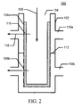
- the filtrate may then been removed from the filter housing through conduits 110a, 110b in a first flow direction 118 as illustrated in FIG. 2 .
- regeneration is desired including, for example, when the pressure drop across the filter assembly exceeds an upper pressure target or the filter cake in the regeneration region exceeds a target thickness, the regeneration process can be initiated. During the regeneration process, as illustrated in FIG.
- the portion of the filter cake in the regeneration region of the filter assembly is reduced or removed through a combination of a reversed fluid flow in a second flow direction 118a, e.g., a backwash flow and ultrasonic agitation provided by one or more ultrasonic transducers 120 that are configured for applying ultrasonic energy to at least a portion of the regeneration region.
- a reversed fluid flow in a second flow direction 118a e.g., a backwash flow and ultrasonic agitation provided by one or more ultrasonic transducers 120 that are configured for applying ultrasonic energy to at least a portion of the regeneration region.
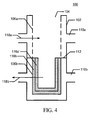
- the removed portions of the filter cake 116a are then drawn into the collection region of the filter assembly by fluid passing through the filter assembly in direction 118b to form an additional filter cake layer 116a' on the remaining portion of the initial filter cake 116b.
- the flow rate and inlet positions of the backwash flow during the regeneration process may be reduced relative to that utilized during the filtration process and configured to reduce the tendency of fines to be removed entirely from the filter assembly.
- the filter assembly may also be oriented in such a manner that the desired redistribution of the removed particulates is assisted by gravity, e.g., by arranging the regeneration region above the collection region within the filter assembly.
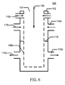
- additional flow paths 118c and/or mechanical baffle or barrier means may also be utilized for suppressing the migration of fines out of the filter assembly during the backwash operation.
- the low flow rate during the regeneration process allows for increased specific area loading on the collection region filter elements than would otherwise be possible at normal operating flow rates. It is anticipated that ultrasonic agitation during at least a portion of the regeneration process will improve the regeneration process and increase the portion of the filter cake that is removed from the regeneration region, particularly at lower flow rates.
- the regeneration region of the filter assembly will tend to be sufficiently unloaded to permit resumption of the filtration the higher flow rates desired during normal filtration operation. As illustrated in FIG. 5 , resumption of the filtration process will result in the formation of an additional layer of filter cake 116c at which point the regeneration process may be repeated.
- the example embodiments of the apparatus disclosed may be adapted to provide for the incremental backwashing of a number of separated filter elements and/or filter regions of the filter assembly during normal operation.
- the filter assembly and filter housing may be configured in a manner that allows a portion of the filtration system to be handled and stored using equipment and techniques adapted for the handling of a similarly configured nuclear fuel assembly in use at the intended site.
- the ultrasonic agitation utilized during the regeneration process may be provided by an ultrasonic fuel cleaning fixture including, for example, the cleaning fixtures disclosed in U.S. Patent No. 6,396,892 , previously adapted for fuel cleaning.
- another conventional or custom-designed ultrasonic agitator may be utilized for applying sufficient ultrasonic energy to the filter assembly to separate a portion of the accumulated particulates and/or filter cake from the regeneration region(s) of the filter assembly when no ultrasonic fuel cleaning system is readily available.
- Alternate embodiments of the filtration system and filter assembly include, but are not limited to, varying the relative areas of the regeneration region and the collection region, configuring the filter assembly to provide a plurality of regeneration regions and/or collection regions, providing a plurality of flow paths that allow for the selective configuration of one or more regions as either a regeneration region or a collection region, thereby allowing modifications of the relative areas of the regeneration region and collection region during service.
- Alternate embodiments of the filtration system and filter assembly also include, but are not limited to, configuring a plurality of filter elements in parallel, series or series/parallel configurations through the use of appropriate conduit arrangements and cooperating valve assemblies or equivalent devices.
- Example embodiments of such configurations include, but are not limited to, staged-filtration arrangements wherein successively smaller particles are captured by each stage of filtration, such as by using media with different effective "micron ratings," pore sizes and/or media depth in a plurality of filter stages.
- Alternate embodiments of the filtration system and filter assembly also include, but are not limited to, configurations that permit use of conventional filter packaging.
- the example embodiments of the methods and apparatus can be achieved using at least one of the conventional filter packages as the regeneration region and at least one of the filter packages as the collection region during backflush operations.
- Alternate embodiments of the filtration system and filter assembly also include, but are not limited to, variations wherein the effective length of the collection region is extended by combining a porous section of the collection region in series with a nonporous section (i.e. , solid tube) and constructing the collection region using media that is less suitable for backwashing (i.e. , a filter assembly construction configured for application of a pressure differential in only a preferred direction).
- a nonporous section i.e. , solid tube
- media that is less suitable for backwashing i.e. , a filter assembly construction configured for application of a pressure differential in only a preferred direction.
- Alternate embodiments of the filtration system and filter assembly also include, but are not limited to, utilizing materials exhibiting enhanced resistance to high radiation fields, utilizing packaging is designed to include a permanent or remotely-operable port, opening or penetration that can be used to drain fluid from the filter by the action of gravity when the filter is maintained in an appropriate position, e.g., an upright position, utilizing packaging that includes a check valve or equivalent structure configured for suppressing or preventing the migration of captured particulates from a filter assembly in the absence of a fluid flow and utilizing packaging designed for the remote operation of valves or equivalent structure that allow the flow path(s) to and from the various regions or sections of the filter assembly to be aligned with various flow sources, conduits and sinks.
- packaging is designed to include a permanent or remotely-operable port, opening or penetration that can be used to drain fluid from the filter by the action of gravity when the filter is maintained in an appropriate position, e.g., an upright position
- packaging that includes a check valve or equivalent structure configured for suppressing or preventing the migration
- Alternate embodiments of the filtration system and filter assembly also include, but are not limited to, utilizing packaging designed for integrating ultrasonic transducers with the remainder of the filter package and including means for monitoring various process parameters such as pressure and flow rate at one or more locations within the filter assembly, filter housing and/or conduits.
- a laboratory scale test was performed to determine the extent to which the life/capacity of a filter could be extended with a method and apparatus according to the example embodiments disclosed herein.
- the test fixture consisted of two 10 inch (25 cm) filter cartridges arranged as shown in FIG. 1 , with the upper cartridge configured as the regeneration region and the lower cartridge configured as the collection region.
- the filter cartridges were loaded with test dust as shown in FIG. 2 until the differential pressure across the filter assembly reached a prescribed end-of-life pressure limit of about 35 psi (0.24 MPa).
- the test fixture was then ultrasonically agitated and a portion of the filter cake was backwashed from the regeneration region into the collection region ( FIGS. 3 and 4 ).
- the filter system was then run in the normal loading configuration ( FIG. 5 ) and the post-regeneration filter differential pressure was recorded. This sequence of operations was then repeated (see FIG. 8 and steps S100 to S112) until the filter assembly became sufficiently loaded that regeneration was not sufficient to reduce the differential pressure sufficiently to reach a baseline value of about 20 psi (0.14 MPa) at which point the test was terminated.
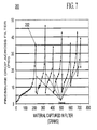
- the differential pressure data and particulate capture data are providing in graph 200 as illustrated in FIG. 7 .
- the backwashing process was found to have increased the particulate holding capacity of the filter cartridges by a factor of approximately 3.3. Upon disassembly of the test fixture, the lower filter cartridge was found to be packed solid with test dust. The test data suggests that the total particulate holding capacity could be increased further by increasing the percentage of filter area in the bottom region.
- the construction of the filter assemblies and, in particular, the filtration media must be configured to allow for the reverse flow associated with the backwashing process and to provide sufficient mechanical strength to withstand the ultrasonic agitation without damaging the media.
- the example embodiments of the filter assembly and methods of operating such filter assemblies may include one or more features including, but not limited to arranging the filter assembly so that a portion of the media is used both for primary filtration (when the filter assembly is new) and for capturing backwashed waste (during regeneration processing). Such a configuration would reduce or eliminate the need to use additional media, flow arrangements or structure to capture the backwashed waste without substantially degrading the performance of the filter assembly relative to a similar filter element not incorporating the internal backwash capture configuration.
- the filter regeneration process relocates waste within the filter to increase the capacity of a disposable filter element.
- Existing systems use ultrasound to remove waste from the media so that it can be flushed out of the filter element, with the waste stream either discharged directly or filtered onto a secondary disposal media.
- all or substantially all of the backwashed waste is maintained within the filter element so that there is no need for additional handling of the hazardous waste and the problems associated therein.
- Ultrasonic agitation facilitates low flow rate backflushing, which in turn permits internal capture of the backflushed waste on the highly loaded region of the filter. Without the ultrasonic agitation, it would be difficult, if not impossible, to generate a sufficiently high backflush flow rate through the regeneration region to dislodge particulate waste while simultaneously filtering that high flow of fluid through the more highly loaded collection region of the filter.
- the filter assembly can be packaged and configured to resemble a nuclear fuel assembly for ease of handling and storage, and for compatibility with an existing ultrasonic fuel cleaning system.
- the filter assemblies according to the example embodiments may be readily adapted to any conventional packaging format including, for example, configurations used by Westinghouse/ABB in the late 1990s in constructing a system (FILDEC) that utilized filters housed in a fuel assembly shaped structure.
Landscapes
- Chemical & Material Sciences (AREA)
- Chemical Kinetics & Catalysis (AREA)
- Filtration Of Liquid (AREA)
- Filtering Of Dispersed Particles In Gases (AREA)
- Separation Using Semi-Permeable Membranes (AREA)
Description
- This application claims priority under 35 U.S.C. § 119(e) from
U.S. Provisional Patent Appl. No. 60/940,928 - Radioactive particulate waste, such as that generated during ultrasonic fuel cleaning of irradiated nuclear fuel assemblies, may be difficult and costly to dispose of. The radioactive aspect of such particulate waste presents unique filtration cost considerations relative to more conventional filtration applications as a result of the various rules and regulations governing handling, shipment, and disposal of the spent or loaded filters. Often, the cost of filtration is dominated by the disposal cost of the contaminated filters.
Accordingly, increasing the particulate holding capacity of each filter will tend to reduce the total filtration cost. - The particulate holding capacity of a membrane-type filter is dependent upon a number of factors including, for example, the available differential pressure across the media, the available area of filter media and the flow rate through the filter. Accordingly, the particulate holding capacity may be increased by using a variety of techniques including, for example, providing additional differential pressure, increasing the amount of media in the filter and/or by reducing the flow rate through the filter.
WO 92/11923 A1 DE 33 35 127 A1 . - Example embodiments of the new filter system and associated methods of filtering utilize a combination of ultrasonically enhanced backwashing and a modified filter media configuration for increasing the specific loading on a portion of the filter media, thereby tending to increase the total particulate holding capacity of the improved filter. Depending on factors such as the filter configuration, the particulate size distribution and the available pressure drop that can be maintained across the filter, it is expected that the particulate holding capacity can be more than doubled relative to a conventional filter having similarly configured filter media.
- The primary applications for the improved filter are expected to be in both boiling water reactor (BWR) and pressurized water reactor (PWR) fuel cleaning applications although those skilled in the will appreciate that increasing the effective filter capacity may be useful in a wide range of applications. It is expected that in the BWR and PWR applications, the filter assembly will be packaged or configured in a form compatible with a conventional fuel assembly location that can, in turn, be cleaned using an appropriate ultrasonic fuel cleaning fixture. For other applications, those skilled in the art will appreciate that a wide range of filter assemblies and ultrasonic fixtures may be adapted to achieve equipment configurations consistent with the disclosed embodiments and for practicing the disclosed methods.
- Equipment and methods consistent with the disclosed embodiments are expected to provide one or more advantages over conventional filtration assemblies and methods. It is expected, for example, that equipment and methods consistent with the disclosed embodiments may include one or more advantages including reducing the cost of the filter media by reducing the volume of filter media required for capturing a given quantity of particulates, increasing the life of the filter assembly by reducing the effective filling rate, reducing the number of contaminated filters that will be stored onsite, reducing the number of filters for disposal and the associated costs and/or may allow for the use of existing ultrasonic cleaning equipment thereby reducing the associated equipment expenses and maintenance.
- While filtration of the particulate waste generated during ultrasonic fuel cleaning waste is expected to be one of the more common uses of the disclosed methods and apparatus, those skilled in the art will appreciate that the disclosure and application are not so limited. For example, it is expected that the disclosed methods and apparatus may have particular utility in other applications including, but not limited to, local filtration of miscellaneous radioactive and non-radioactive waste in spent fuel pools, reactor cavities and other vessels or regions that tend to collect, or be particularly sensitive to, particular contamination. Example embodiments may include, without limitation, underwater vacuuming of swarf and/or other machining debris that could be generated and/or removed during plant maintenance activities or plant decommissioning. Other example embodiments may include, without limitation, underwater vacuuming as part of general pool/cavity cleanup, and local area filtration to improve water clarity and/or area dose rates, large scale filtration to reduce or eliminate number of filters used in fuel pool and reactor cavity filtration systems, any other filtration application where the required filter particulate holding capacity is beyond that which can be achieved using traditional membrane filters and/or those applications in which it is desirable to contain all of the captured material within the original filter for ultimate disposal.
- Even other example embodiments may include, without limitation, regeneration of filter pre-coat layers. For example, some filtration applications include a pre-coat layer that is applied to the media before use in the primary filtration application. The apparatus and methods disclosed herein could be utilized for removing the spent/clogged pre-coat layer from the active filtration region, allowing the application of a new pre-coat on the cleaned filter layer without needing to dispose of the removed pre-coat media separately.
- Prior art methods include various sequences and configurations for cleaning and backwashing filter media including some in which backwashing, with or without the application of ultrasonics, is used in regenerating filtration media by removing the particulates from the media so that it can be disposed of elsewhere (e.g., discharged to a waste water system). The example apparatus and methods disclosed herein, however, provide means for increasing filter capacity through periodic relocation of particulates within a filter assembly. The relocation of the particulates within the filter assembly onto/into a designated collection region allows another region of the filter assembly to be "regenerated" to provide a renewed filter region. The availability of this regeneration region, in turn, allows the filter assembly to continue providing useful filtration function well beyond the point where conventionally arranged and operated filters would require replacement to maintain normal operation.
- Example embodiments described below will be more clearly understood when the detailed description is considered in conjunction with the accompanying drawings, in which:
-
FIG. 1 illustrates an example embodiment of an apparatus suitable for practicing the methods detailed in the detailed disclosure; -
FIGS. 2-5 illustrate an example embodiment of a filtration method as detailed in the disclosure below; -
FIG. 6 illustrates another example embodiment of an apparatus suitable for practicing the methods detailed in the detailed disclosure; -
FIG. 7 illustrates pressure and particulate capture data generated practicing an embodiment of the methods described on an example embodiment of a suitable apparatus for practicing the method; -
FIG. 8 illustrates an example embodiment of steps that could be utilized in practicing an example embodiment of the method as illustrated inFIGS. 2-5 ; and - It should be noted that these Figures are intended to illustrate the general characteristics of methods, structure and/or materials utilized in certain example embodiments and to supplement the written description provided below. These drawings are not, however, drawn to scale and do not precisely reflect the precise structural or performance characteristics of any given embodiment and should not, therefore, be interpreted as defining or limiting the range of values or properties encompassed by example embodiments.
Further, the drawings have been simplified by omitting peripheral structure including, for example, piping, valves, pumps, power supplies, cables, controllers and other equipment, with the understanding that those skilled in the art would be able to determine and construct the peripheral structure necessary for the full range of embodiments disclosed herein and obvious variations thereof. - An example embodiment of an
apparatus 100 for practicing the disclosed methods is illustrated inFIG. 1 and includes afilter housing 102 having aprimary inlet 104 for introducing contaminated fluid in aninlet direction 108 into the filter assembly that, in turn, includes aregeneration region 106a and acollection region 106b. Fluid passing through the regeneration region and collection region of the filter assembly is then removed from the filter housing through associatedconduits flange 112 or equivalent structure for separating the flows and defining first and second flow paths. These flow paths includecorresponding plenum regions - As will be appreciated by those skilled in the art, the filter assembly may comprise a unitary structure, i.e., one single filter element, or may comprise a plurality of filter elements that cooperate to form a complete assembly. As will also be appreciated by those skilled in the art, embodiments including a plurality of filter elements may utilize a plurality of filter housing sub-units that cooperate to form a complete filter housing, thereby increasing the range of apparatus configurations that may be utilized to practice methods consistent with those detailed below. For example, a parallel structure would allow for alternating filtration and regeneration operations between two or more corresponding flow paths to allow for off-line regeneration while maintaining the filtration function of the apparatus.
- As illustrated in
FIGS. 2-5 , during a filtration operation a layer of particulates or "filter cake" 116 may be formed on the surfaces of the regeneration and collection regions of the filter assembly as a particulate containing fluid is fed into the filter assembly and passed through the filter assembly. The filtrate may then been removed from the filter housing throughconduits first flow direction 118 as illustrated inFIG. 2 . When regeneration is desired including, for example, when the pressure drop across the filter assembly exceeds an upper pressure target or the filter cake in the regeneration region exceeds a target thickness, the regeneration process can be initiated. During the regeneration process, as illustrated inFIG. 3 , the portion of the filter cake in the regeneration region of the filter assembly is reduced or removed through a combination of a reversed fluid flow in asecond flow direction 118a, e.g., a backwash flow and ultrasonic agitation provided by one or moreultrasonic transducers 120 that are configured for applying ultrasonic energy to at least a portion of the regeneration region. - As illustrated in
FIG. 4 , the removed portions of thefilter cake 116a are then drawn into the collection region of the filter assembly by fluid passing through the filter assembly indirection 118b to form an additionalfilter cake layer 116a' on the remaining portion of theinitial filter cake 116b. The flow rate and inlet positions of the backwash flow during the regeneration process may be reduced relative to that utilized during the filtration process and configured to reduce the tendency of fines to be removed entirely from the filter assembly. The filter assembly may also be oriented in such a manner that the desired redistribution of the removed particulates is assisted by gravity, e.g., by arranging the regeneration region above the collection region within the filter assembly. As illustrated inFIG. 6 ,additional flow paths 118c and/or mechanical baffle or barrier means (not shown) may also be utilized for suppressing the migration of fines out of the filter assembly during the backwash operation. - It is believed that the low flow rate during the regeneration process allows for increased specific area loading on the collection region filter elements than would otherwise be possible at normal operating flow rates. It is anticipated that ultrasonic agitation during at least a portion of the regeneration process will improve the regeneration process and increase the portion of the filter cake that is removed from the regeneration region, particularly at lower flow rates.
- After regeneration, the regeneration region of the filter assembly will tend to be sufficiently unloaded to permit resumption of the filtration the higher flow rates desired during normal filtration operation. As illustrated in
FIG. 5 , resumption of the filtration process will result in the formation of an additional layer offilter cake 116c at which point the regeneration process may be repeated. As will be appreciated by those skilled in the art, the example embodiments of the apparatus disclosed may be adapted to provide for the incremental backwashing of a number of separated filter elements and/or filter regions of the filter assembly during normal operation. - For those filtration systems intended for use in conjunction with nuclear fuel cleaning applications, the filter assembly and filter housing may be configured in a manner that allows a portion of the filtration system to be handled and stored using equipment and techniques adapted for the handling of a similarly configured nuclear fuel assembly in use at the intended site. By utilizing a common configuration, the ultrasonic agitation utilized during the regeneration process may be provided by an ultrasonic fuel cleaning fixture including, for example, the cleaning fixtures disclosed in
U.S. Patent No. 6,396,892 , previously adapted for fuel cleaning. Alternatively, another conventional or custom-designed ultrasonic agitator may be utilized for applying sufficient ultrasonic energy to the filter assembly to separate a portion of the accumulated particulates and/or filter cake from the regeneration region(s) of the filter assembly when no ultrasonic fuel cleaning system is readily available. - Alternate embodiments of the filtration system and filter assembly, include, but are not limited to, varying the relative areas of the regeneration region and the collection region, configuring the filter assembly to provide a plurality of regeneration regions and/or collection regions, providing a plurality of flow paths that allow for the selective configuration of one or more regions as either a regeneration region or a collection region, thereby allowing modifications of the relative areas of the regeneration region and collection region during service.
- Alternate embodiments of the filtration system and filter assembly, also include, but are not limited to, configuring a plurality of filter elements in parallel, series or series/parallel configurations through the use of appropriate conduit arrangements and cooperating valve assemblies or equivalent devices. Example embodiments of such configurations include, but are not limited to, staged-filtration arrangements wherein successively smaller particles are captured by each stage of filtration, such as by using media with different effective "micron ratings," pore sizes and/or media depth in a plurality of filter stages.
- Alternate embodiments of the filtration system and filter assembly, also include, but are not limited to, configurations that permit use of conventional filter packaging. When using conventional filter packaging, the example embodiments of the methods and apparatus can be achieved using at least one of the conventional filter packages as the regeneration region and at least one of the filter packages as the collection region during backflush operations.
- Alternate embodiments of the filtration system and filter assembly, also include, but are not limited to, variations wherein the effective length of the collection region is extended by combining a porous section of the collection region in series with a nonporous section (i.e., solid tube) and constructing the collection region using media that is less suitable for backwashing (i.e., a filter assembly construction configured for application of a pressure differential in only a preferred direction).
- Alternate embodiments of the filtration system and filter assembly, also include, but are not limited to, utilizing materials exhibiting enhanced resistance to high radiation fields, utilizing packaging is designed to include a permanent or remotely-operable port, opening or penetration that can be used to drain fluid from the filter by the action of gravity when the filter is maintained in an appropriate position, e.g., an upright position, utilizing packaging that includes a check valve or equivalent structure configured for suppressing or preventing the migration of captured particulates from a filter assembly in the absence of a fluid flow and utilizing packaging designed for the remote operation of valves or equivalent structure that allow the flow path(s) to and from the various regions or sections of the filter assembly to be aligned with various flow sources, conduits and sinks.
- Alternate embodiments of the filtration system and filter assembly, also include, but are not limited to, utilizing packaging designed for integrating ultrasonic transducers with the remainder of the filter package and including means for monitoring various process parameters such as pressure and flow rate at one or more locations within the filter assembly, filter housing and/or conduits.
- As will be appreciated by those skilled in the art, the features and elements of the alternative example embodiments detailed above may be combined to produce additional embodiments that would be suitable for practicing methods in accord with the example embodiments disclosed.
- A laboratory scale test was performed to determine the extent to which the life/capacity of a filter could be extended with a method and apparatus according to the example embodiments disclosed herein. The test fixture consisted of two 10 inch (25 cm) filter cartridges arranged as shown in
FIG. 1 , with the upper cartridge configured as the regeneration region and the lower cartridge configured as the collection region. The filter cartridges were loaded with test dust as shown inFIG. 2 until the differential pressure across the filter assembly reached a prescribed end-of-life pressure limit of about 35 psi (0.24 MPa). - The test fixture was then ultrasonically agitated and a portion of the filter cake was backwashed from the regeneration region into the collection region (
FIGS. 3 and4 ). The filter system was then run in the normal loading configuration (FIG. 5 ) and the post-regeneration filter differential pressure was recorded. This sequence of operations was then repeated (seeFIG. 8 and steps S100 to S112) until the filter assembly became sufficiently loaded that regeneration was not sufficient to reduce the differential pressure sufficiently to reach a baseline value of about 20 psi (0.14 MPa) at which point the test was terminated. The differential pressure data and particulate capture data are providing ingraph 200 as illustrated inFIG. 7 . The backwashing process was found to have increased the particulate holding capacity of the filter cartridges by a factor of approximately 3.3. Upon disassembly of the test fixture, the lower filter cartridge was found to be packed solid with test dust. The test data suggests that the total particulate holding capacity could be increased further by increasing the percentage of filter area in the bottom region. - As will be appreciated by those skilled in the art, the construction of the filter assemblies and, in particular, the filtration media, must be configured to allow for the reverse flow associated with the backwashing process and to provide sufficient mechanical strength to withstand the ultrasonic agitation without damaging the media.
- The example embodiments of the filter assembly and methods of operating such filter assemblies may include one or more features including, but not limited to arranging the filter assembly so that a portion of the media is used both for primary filtration (when the filter assembly is new) and for capturing backwashed waste (during regeneration processing). Such a configuration would reduce or eliminate the need to use additional media, flow arrangements or structure to capture the backwashed waste without substantially degrading the performance of the filter assembly relative to a similar filter element not incorporating the internal backwash capture configuration.
- The filter regeneration process relocates waste within the filter to increase the capacity of a disposable filter element. Existing systems use ultrasound to remove waste from the media so that it can be flushed out of the filter element, with the waste stream either discharged directly or filtered onto a secondary disposal media. In a method according to an example embodiment, all or substantially all of the backwashed waste is maintained within the filter element so that there is no need for additional handling of the hazardous waste and the problems associated therein.
- The combination of ultrasonic agitation and low flow rate backwashing of clean region. Ultrasonic agitation facilitates low flow rate backflushing, which in turn permits internal capture of the backflushed waste on the highly loaded region of the filter. Without the ultrasonic agitation, it would be difficult, if not impossible, to generate a sufficiently high backflush flow rate through the regeneration region to dislodge particulate waste while simultaneously filtering that high flow of fluid through the more highly loaded collection region of the filter.
- In the example embodiments, the filter assembly can be packaged and configured to resemble a nuclear fuel assembly for ease of handling and storage, and for compatibility with an existing ultrasonic fuel cleaning system. As will be appreciated by those skilled in the art, the filter assemblies according to the example embodiments may be readily adapted to any conventional packaging format including, for example, configurations used by Westinghouse/ABB in the late 1990s in constructing a system (FILDEC) that utilized filters housed in a fuel assembly shaped structure.
- While the disclosed inventions have been particularly shown and described with reference to examples embodiments thereof, these inventions should not be construed as being limited to the particular embodiments set forth herein; rather, these example embodiments are provided to convey more fully the concept of the invention to those skilled in the art.
Claims (6)
- A filtration system (100) for filtering fluid containing radioactive particulate waste, the filtration system having a filtration mode and a regeneration mode, the filtration system comprising:a filter housing (102);a filter assembly arranged in the filter housing, the filter assembly comprising a regeneration region (106a) and a collection region (106b);a flange (112) or equivalent structure defming first and second plenum regions (114a, 114b) between external filter assembly surfaces and interior surfaces of the filter housing for providing differential flows through the regeneration region (106a) and the collection region (106b); andan ultrasonic transducer (120) configured for applying energy to the regeneration region of the filter assembly in the regeneration mode of said filtration system,said filter housing having:a primary inlet (104) for introducing a fluid containing radioactive particulate waste into the filtration system in the filtration mode of said filtration system;a regeneration region conduit (110a) fluidly connected with the first plenum region (114a) and the regeneration region (106a) of the filter assembly; anda collection region conduit (110b) fluidly connected with the second plenum region (114b) and the collection region (106b) of the filter assembly,wherein the filtration system is configured, in the filtration mode, to pass the fluid from the primary inlet (104) through the regeneration region (106a) as well as the collection region (106b) of the filter assembly to the regeneration region conduit (110a) and collection region conduit (110b) in a first flow direction (118), so as to form a layer (116) of radioactive particulates from said fluid on a surface of said regeneration and collection regions of the filter assembly while removing the filtrate from said filter housing through said regeneration region conduit (110a) as well as said collection region conduit (110b), andwherein the filtration system is configured, in the regeneration mode, to pass a reversed fluid flow from the regeneration region conduit (110a) through the regeneration region (106a) in a second flow direction (118a), opposite said first flow direction, while agitating said ultrasonic transducer (120), such that the reversed flow then continues through said collection region (106b) of the filter assembly in said first flow direction (118b) to said collection region conduit (110b), so as to cause relocation of at least portions of said layer of radioactive particulates from the surface of said regeneration region (106a) to the surface of said collection region (106b) of the filter assembly.
- The filtration system according to claim 1, wherein:the filter assembly utilizes a unitary construction.
- The filtration system according to claim 1, wherein:the filter assembly utilizes a modular multi-part construction.
- The filtration system according to claim 1, further comprising:a first pressure sensor and a second pressure sensor arranged for sensing a pressure drop across the filter assembly.
- The filtration system of claim 1, wherein:
the collection filter region (106b) is configured for collecting and retaining particulates released from the regeneration filter region (106a). - A method of filtering fluid containing radioactive particulate waste, the method involving:providing a filtration system being operable in a filtration mode and a regeneration mode, and comprising:a filter housing (102);a filter assembly arranged in the filter housing and having a regeneration region (106a) and a collection region (106b);a flange (112) or equivalent structure defining first and second plenum regions (114a, 114b) between external filter assembly surfaces and interior surfaces of the filter housing for providing differential flows through the regeneration region (106a) and the collection region (106b); andan ultrasonic transducer (120) configured for applying energy to the regeneration region of the filter assembly in the regeneration mode of said filtration system,wherein said filter housing has:a primary inlet (104);a regeneration region conduit (110a) fluidly connected with the first plenum region (114a) and the regeneration region (106a) of the filter assembly; anda collection region conduit (110b) fluidly connected with the second plenum region (114b) and the collection region (106b) of the filter assembly;introducing, in the filtration mode, a fluid containing radioactive particulate waste into the filtration system through the primary inlet (104);passing, in the filtration mode, the fluid from the primary inlet (104) through the regeneration region (106a) as well as the collection region (106b) of the filter assembly to the regeneration region conduit (110a) and collection region conduit (110b) in a first flow direction (118), so as to form a layer (116) of radioactive particulates from said fluid on a surface of said regeneration and collection regions of the filter assembly while removing the filtrate from said filter housing through said regeneration region conduit (110a) as well as said collection region conduit (110b); andpassing, in the regeneration mode, a reversed fluid flow from the regeneration region conduit (110a) through the regeneration region (106a) in a second flow direction (118a), opposite said first flow direction, while agitating said ultrasonic transducer (120), such that the reversed flow then continues through said collection region (106b) of the filter assembly in said first flow direction (118b) to said collection region conduit (110b), so as to cause relocation of at least portions of said layer of radioactive particulates from the surface of said regeneration region (106a) to the surface of said collection region (106b) of the filter assembly.
Applications Claiming Priority (2)
| Application Number | Priority Date | Filing Date | Title |
|---|---|---|---|
| US94092807P | 2007-05-30 | 2007-05-30 | |
| PCT/US2008/065433 WO2008151090A1 (en) | 2007-05-30 | 2008-05-30 | Apparatus and method for increasing filter capacity using ultrasonic regeneration |
Publications (4)
| Publication Number | Publication Date |
|---|---|
| EP2188813A1 EP2188813A1 (en) | 2010-05-26 |
| EP2188813A4 EP2188813A4 (en) | 2011-05-25 |
| EP2188813B1 true EP2188813B1 (en) | 2013-07-03 |
| EP2188813B9 EP2188813B9 (en) | 2013-10-23 |
Family
ID=40086929
Family Applications (1)
| Application Number | Title | Priority Date | Filing Date |
|---|---|---|---|
| EP08756577.6A Active EP2188813B9 (en) | 2007-05-30 | 2008-05-30 | Apparatus and method for increasing filter capacity using ultrasonic regeneration |
Country Status (7)
| Country | Link |
|---|---|
| US (1) | US8052879B2 (en) |
| EP (1) | EP2188813B9 (en) |
| JP (1) | JP5143226B2 (en) |
| KR (1) | KR101379207B1 (en) |
| CN (1) | CN101720487B (en) |
| ES (1) | ES2424440T3 (en) |
| WO (1) | WO2008151090A1 (en) |
Cited By (1)
| Publication number | Priority date | Publication date | Assignee | Title |
|---|---|---|---|---|
| CN107321065A (en) * | 2017-07-05 | 2017-11-07 | 浙江大学 | A kind of high efficiency composition ultrasonic filters that can be recycled |
Families Citing this family (17)
| Publication number | Priority date | Publication date | Assignee | Title |
|---|---|---|---|---|
| EP2188813B9 (en) * | 2007-05-30 | 2013-10-23 | Dominion Engineering, Inc. | Apparatus and method for increasing filter capacity using ultrasonic regeneration |
| US9193924B2 (en) * | 2011-06-16 | 2015-11-24 | Uop Llc | Methods and apparatuses for forming low-metal biomass-derived pyrolysis oil |
| US9767927B2 (en) | 2011-12-12 | 2017-09-19 | Dominion Engineering, Inc. | Particulate removal system |
| CN102989223A (en) * | 2012-12-04 | 2013-03-27 | 南通海利源船舶设备工程有限公司 | Automatic backwash filtering device |
| US9757675B2 (en) * | 2013-01-29 | 2017-09-12 | Corning Incorporated | Partial wall-flow filter and method |
| US20140238242A1 (en) * | 2013-02-28 | 2014-08-28 | Corning Incorporated | Ceramic partial wall-flow filter with low deep bed |
| US9707498B2 (en) * | 2013-03-14 | 2017-07-18 | Filtration Technology Corporation | Filtration system and method |
| AT513225B1 (en) * | 2013-11-29 | 2015-09-15 | Kurt Ing Gassner | Process for the filtration of liquids |
| EP3510601B1 (en) * | 2016-09-06 | 2021-05-12 | Westinghouse Electric Sweden AB | A fuel assembly |
| JP7101687B2 (en) * | 2017-04-20 | 2022-07-15 | ドミニオン エンジニアリング,インク. | Modular water purification system for nuclear plants |
| CN106984093A (en) * | 2017-06-02 | 2017-07-28 | 江苏元升厨卫电器有限公司 | Self-cleaning ultrasonic water purifier |
| AU2019284513A1 (en) * | 2018-06-13 | 2021-01-14 | Cargill, Incorporated | Liquid discharge filter and its use |
| US12377376B2 (en) | 2019-03-03 | 2025-08-05 | Vrd, Llc | Method and apparatus for enhanced separation and removal of contaminants and irradiated particulates from fluids |
| CA3136368A1 (en) | 2019-04-23 | 2020-10-29 | Vrd, Llc | Method and apparatus for improved removal and retention of radioactive particulates from fluids |
| CN111188383B (en) * | 2020-03-04 | 2021-06-25 | 刘举 | Stable filtering centralized water supply system and centralized water supply method |
| CN112742088A (en) * | 2021-01-05 | 2021-05-04 | 广州市智勋电子商务有限公司 | Sanitary towel is cooked and is used waste water filtration equipment |
| WO2024112658A1 (en) * | 2022-11-21 | 2024-05-30 | Basf Corporation | Filter cake sonication |
Citations (3)
| Publication number | Priority date | Publication date | Assignee | Title |
|---|---|---|---|---|
| US5171433A (en) * | 1990-01-24 | 1992-12-15 | Peretz Rosenberg | Back-flushable filter |
| WO2001038744A1 (en) * | 1999-11-20 | 2001-05-31 | Fsp-Holding Ag | Filter device of a hydraulic systems |
| EP1785178A1 (en) * | 2005-11-14 | 2007-05-16 | Odis Irrigation Equipment Limited | Method for cleaning a filtering system and a filtering system having cleaning capabilities. |
Family Cites Families (17)
| Publication number | Priority date | Publication date | Assignee | Title |
|---|---|---|---|---|
| US4482461A (en) * | 1982-12-20 | 1984-11-13 | French Systems, Inc. | Backwash control for constant volume-pressure filtration system |
| DE3335127A1 (en) | 1983-09-28 | 1985-04-11 | Wacker-Chemie GmbH, 8000 München | Process for removing mercury from aqueous liquids |
| JPS61249513A (en) * | 1985-04-30 | 1986-11-06 | Mitsuo Yanagisawa | Filter and filtering method |
| JPH0657288B2 (en) * | 1986-03-25 | 1994-08-03 | 旭硝子株式会社 | Patty Yule Trap |
| US5298161A (en) | 1991-01-07 | 1994-03-29 | Erosonic Ag | Apparatus for cleaning the working liquid of an EDM or ECM machine |
| GB9505038D0 (en) * | 1994-10-01 | 1995-05-03 | Imas Uk Ltd | A filter, apparatus including the filter and a method of use of the apparatus |
| DE4446261C2 (en) * | 1994-12-23 | 1996-10-31 | Mann & Hummel Filter | Gap filter for liquids or gases |
| US6251294B1 (en) * | 1997-12-22 | 2001-06-26 | Delaware Capital Formation, Inc. | Ultrasonic filter regenerating apparatus and method |
| US20010050095A1 (en) | 1998-04-21 | 2001-12-13 | Kubota Corporation | Method and apparatus of regenerating filtration membrane cartridge for activated sludge |
| US6395186B1 (en) * | 2000-06-20 | 2002-05-28 | Delaware Capital Formation, Inc. | Pressure liquid filtration with ultrasonic bridging prevention |
| JP2002336615A (en) * | 2001-05-14 | 2002-11-26 | Kiyo Kuroda | Filtration device |
| GB0314243D0 (en) * | 2003-06-18 | 2003-07-23 | Johnson Matthey Plc | Engine exhaust gas treatment |
| US7083735B2 (en) * | 2003-09-03 | 2006-08-01 | Laing David A | High debris content strainer |
| JP4425608B2 (en) * | 2003-11-13 | 2010-03-03 | 株式会社三鷹工業所 | Filtration method in filtration device and filtration device |
| CN1226069C (en) * | 2003-11-14 | 2005-11-09 | 安泰科技股份有限公司 | Indirect type gas assisting liquid reverse flushing filter apparatus and cleaning method thereof |
| US7445716B2 (en) * | 2004-01-05 | 2008-11-04 | Eaton Lp | Crossflow pressure liquid filtration with ultrasonic enhancement |
| EP2188813B9 (en) * | 2007-05-30 | 2013-10-23 | Dominion Engineering, Inc. | Apparatus and method for increasing filter capacity using ultrasonic regeneration |
-
2008
- 2008-05-30 EP EP08756577.6A patent/EP2188813B9/en active Active
- 2008-05-30 WO PCT/US2008/065433 patent/WO2008151090A1/en not_active Ceased
- 2008-05-30 CN CN200880022725.3A patent/CN101720487B/en active Active
- 2008-05-30 KR KR1020107001351A patent/KR101379207B1/en active Active
- 2008-05-30 JP JP2010510542A patent/JP5143226B2/en active Active
- 2008-05-30 ES ES08756577T patent/ES2424440T3/en active Active
- 2008-05-30 US US12/130,866 patent/US8052879B2/en active Active
Patent Citations (3)
| Publication number | Priority date | Publication date | Assignee | Title |
|---|---|---|---|---|
| US5171433A (en) * | 1990-01-24 | 1992-12-15 | Peretz Rosenberg | Back-flushable filter |
| WO2001038744A1 (en) * | 1999-11-20 | 2001-05-31 | Fsp-Holding Ag | Filter device of a hydraulic systems |
| EP1785178A1 (en) * | 2005-11-14 | 2007-05-16 | Odis Irrigation Equipment Limited | Method for cleaning a filtering system and a filtering system having cleaning capabilities. |
Cited By (1)
| Publication number | Priority date | Publication date | Assignee | Title |
|---|---|---|---|---|
| CN107321065A (en) * | 2017-07-05 | 2017-11-07 | 浙江大学 | A kind of high efficiency composition ultrasonic filters that can be recycled |
Also Published As
| Publication number | Publication date |
|---|---|
| EP2188813A1 (en) | 2010-05-26 |
| US8052879B2 (en) | 2011-11-08 |
| US20080296236A1 (en) | 2008-12-04 |
| CN101720487A (en) | 2010-06-02 |
| WO2008151090A1 (en) | 2008-12-11 |
| JP5143226B2 (en) | 2013-02-13 |
| JP2010528838A (en) | 2010-08-26 |
| KR101379207B1 (en) | 2014-03-31 |
| EP2188813A4 (en) | 2011-05-25 |
| KR20100030652A (en) | 2010-03-18 |
| ES2424440T3 (en) | 2013-10-02 |
| EP2188813B9 (en) | 2013-10-23 |
| CN101720487B (en) | 2014-03-05 |
Similar Documents
| Publication | Publication Date | Title |
|---|---|---|
| EP2188813B9 (en) | Apparatus and method for increasing filter capacity using ultrasonic regeneration | |
| CN110573464B (en) | Modular water purification system for nuclear power plants | |
| CN104918676B (en) | Liquid Filtration Device | |
| US8771509B2 (en) | Purifying device for sludge under water and method for operating the same | |
| US6197188B1 (en) | Filtration system for concentrating radioactive debris | |
| US20030164342A1 (en) | Dewatering method and device | |
| JPS589687B2 (en) | How to play the filter | |
| JPH11510095A (en) | Hybrid filter system and process fluid filtration method | |
| US6156194A (en) | Magnetic filtration system for minimizing radioactive waste during abrasive waterjet cutting | |
| US12548685B2 (en) | Method and apparatus for improved removal and retention of radioactive particulates from fluids | |
| CN204637788U (en) | Microporous medium purging system | |
| JP4919694B2 (en) | Radioactive waste recovery equipment | |
| CN211800065U (en) | Low-pressure cross-flow type filtering device and system | |
| CN217202269U (en) | Water purifier | |
| JP5885958B2 (en) | Radiation contaminant removal unit and decontamination method | |
| CN110357292A (en) | A kind of nuclear waste water processing system | |
| TWI482175B (en) | Underwater slag purification device and its operation method | |
| JP2723323B2 (en) | Ceramic filtration equipment | |
| WO1999063548A1 (en) | A cleaning device for a nuclear power plant | |
| JPH02284607A (en) | Filter device | |
| JPS6283003A (en) | Filtration desalination equipment | |
| JPH02180608A (en) | Apparatus for treating water produced in cask for use in transportation of used fuel | |
| JPH02139008A (en) | How to clean the filter | |
| JPH0740079B2 (en) | Combustible powder oxine charcoal filter used for purification of water containing radionuclide |
Legal Events
| Date | Code | Title | Description |
|---|---|---|---|
| PUAI | Public reference made under article 153(3) epc to a published international application that has entered the european phase |
Free format text: ORIGINAL CODE: 0009012 |
|
| 17P | Request for examination filed |
Effective date: 20091130 |
|
| AK | Designated contracting states |
Kind code of ref document: A1 Designated state(s): AT BE BG CH CY CZ DE DK EE ES FI FR GB GR HR HU IE IS IT LI LT LU LV MC MT NL NO PL PT RO SE SI SK TR |
|
| AX | Request for extension of the european patent |
Extension state: AL BA MK RS |
|
| DAX | Request for extension of the european patent (deleted) | ||
| A4 | Supplementary search report drawn up and despatched |
Effective date: 20110429 |
|
| 17Q | First examination report despatched |
Effective date: 20111230 |
|
| REG | Reference to a national code |
Ref country code: DE Ref legal event code: R079 Ref document number: 602008025765 Country of ref document: DE Free format text: PREVIOUS MAIN CLASS: G21C0015000000 Ipc: B01D0029230000 |
|
| RIC1 | Information provided on ipc code assigned before grant |
Ipc: B01D 29/72 20060101ALI20121121BHEP Ipc: B01D 29/23 20060101AFI20121121BHEP |
|
| GRAP | Despatch of communication of intention to grant a patent |
Free format text: ORIGINAL CODE: EPIDOSNIGR1 |
|
| GRAS | Grant fee paid |
Free format text: ORIGINAL CODE: EPIDOSNIGR3 |
|
| GRAA | (expected) grant |
Free format text: ORIGINAL CODE: 0009210 |
|
| AK | Designated contracting states |
Kind code of ref document: B1 Designated state(s): AT BE BG CH CY CZ DE DK EE ES FI FR GB GR HR HU IE IS IT LI LT LU LV MC MT NL NO PL PT RO SE SI SK TR |
|
| REG | Reference to a national code |
Ref country code: GB Ref legal event code: FG4D |
|
| REG | Reference to a national code |
Ref country code: CH Ref legal event code: EP Ref country code: AT Ref legal event code: REF Ref document number: 619364 Country of ref document: AT Kind code of ref document: T Effective date: 20130715 |
|
| REG | Reference to a national code |
Ref country code: IE Ref legal event code: FG4D |
|
| REG | Reference to a national code |
Ref country code: DE Ref legal event code: R096 Ref document number: 602008025765 Country of ref document: DE Effective date: 20130829 |
|
| REG | Reference to a national code |
Ref country code: ES Ref legal event code: FG2A Ref document number: 2424440 Country of ref document: ES Kind code of ref document: T3 Effective date: 20131002 |
|
| REG | Reference to a national code |
Ref country code: SE Ref legal event code: TRGR |
|
| PG25 | Lapsed in a contracting state [announced via postgrant information from national office to epo] |
Ref country code: SI Free format text: LAPSE BECAUSE OF FAILURE TO SUBMIT A TRANSLATION OF THE DESCRIPTION OR TO PAY THE FEE WITHIN THE PRESCRIBED TIME-LIMIT Effective date: 20130703 |
|
| REG | Reference to a national code |
Ref country code: AT Ref legal event code: MK05 Ref document number: 619364 Country of ref document: AT Kind code of ref document: T Effective date: 20130703 |
|
| REG | Reference to a national code |
Ref country code: NL Ref legal event code: VDEP Effective date: 20130703 |
|
| REG | Reference to a national code |
Ref country code: LT Ref legal event code: MG4D |
|
| PG25 | Lapsed in a contracting state [announced via postgrant information from national office to epo] |
Ref country code: PT Free format text: LAPSE BECAUSE OF FAILURE TO SUBMIT A TRANSLATION OF THE DESCRIPTION OR TO PAY THE FEE WITHIN THE PRESCRIBED TIME-LIMIT Effective date: 20131104 Ref country code: NO Free format text: LAPSE BECAUSE OF FAILURE TO SUBMIT A TRANSLATION OF THE DESCRIPTION OR TO PAY THE FEE WITHIN THE PRESCRIBED TIME-LIMIT Effective date: 20131003 Ref country code: IS Free format text: LAPSE BECAUSE OF FAILURE TO SUBMIT A TRANSLATION OF THE DESCRIPTION OR TO PAY THE FEE WITHIN THE PRESCRIBED TIME-LIMIT Effective date: 20131103 Ref country code: AT Free format text: LAPSE BECAUSE OF FAILURE TO SUBMIT A TRANSLATION OF THE DESCRIPTION OR TO PAY THE FEE WITHIN THE PRESCRIBED TIME-LIMIT Effective date: 20130703 Ref country code: CY Free format text: LAPSE BECAUSE OF FAILURE TO SUBMIT A TRANSLATION OF THE DESCRIPTION OR TO PAY THE FEE WITHIN THE PRESCRIBED TIME-LIMIT Effective date: 20130828 Ref country code: LT Free format text: LAPSE BECAUSE OF FAILURE TO SUBMIT A TRANSLATION OF THE DESCRIPTION OR TO PAY THE FEE WITHIN THE PRESCRIBED TIME-LIMIT Effective date: 20130703 Ref country code: HR Free format text: LAPSE BECAUSE OF FAILURE TO SUBMIT A TRANSLATION OF THE DESCRIPTION OR TO PAY THE FEE WITHIN THE PRESCRIBED TIME-LIMIT Effective date: 20130703 |
|
| PG25 | Lapsed in a contracting state [announced via postgrant information from national office to epo] |
Ref country code: FI Free format text: LAPSE BECAUSE OF FAILURE TO SUBMIT A TRANSLATION OF THE DESCRIPTION OR TO PAY THE FEE WITHIN THE PRESCRIBED TIME-LIMIT Effective date: 20130703 Ref country code: PL Free format text: LAPSE BECAUSE OF FAILURE TO SUBMIT A TRANSLATION OF THE DESCRIPTION OR TO PAY THE FEE WITHIN THE PRESCRIBED TIME-LIMIT Effective date: 20130703 Ref country code: LV Free format text: LAPSE BECAUSE OF FAILURE TO SUBMIT A TRANSLATION OF THE DESCRIPTION OR TO PAY THE FEE WITHIN THE PRESCRIBED TIME-LIMIT Effective date: 20130703 Ref country code: GR Free format text: LAPSE BECAUSE OF FAILURE TO SUBMIT A TRANSLATION OF THE DESCRIPTION OR TO PAY THE FEE WITHIN THE PRESCRIBED TIME-LIMIT Effective date: 20131004 Ref country code: NL Free format text: LAPSE BECAUSE OF FAILURE TO SUBMIT A TRANSLATION OF THE DESCRIPTION OR TO PAY THE FEE WITHIN THE PRESCRIBED TIME-LIMIT Effective date: 20130703 |
|
| PG25 | Lapsed in a contracting state [announced via postgrant information from national office to epo] |
Ref country code: CY Free format text: LAPSE BECAUSE OF FAILURE TO SUBMIT A TRANSLATION OF THE DESCRIPTION OR TO PAY THE FEE WITHIN THE PRESCRIBED TIME-LIMIT Effective date: 20130703 |
|
| PG25 | Lapsed in a contracting state [announced via postgrant information from national office to epo] |
Ref country code: DK Free format text: LAPSE BECAUSE OF FAILURE TO SUBMIT A TRANSLATION OF THE DESCRIPTION OR TO PAY THE FEE WITHIN THE PRESCRIBED TIME-LIMIT Effective date: 20130703 Ref country code: EE Free format text: LAPSE BECAUSE OF FAILURE TO SUBMIT A TRANSLATION OF THE DESCRIPTION OR TO PAY THE FEE WITHIN THE PRESCRIBED TIME-LIMIT Effective date: 20130703 Ref country code: SK Free format text: LAPSE BECAUSE OF FAILURE TO SUBMIT A TRANSLATION OF THE DESCRIPTION OR TO PAY THE FEE WITHIN THE PRESCRIBED TIME-LIMIT Effective date: 20130703 Ref country code: CZ Free format text: LAPSE BECAUSE OF FAILURE TO SUBMIT A TRANSLATION OF THE DESCRIPTION OR TO PAY THE FEE WITHIN THE PRESCRIBED TIME-LIMIT Effective date: 20130703 Ref country code: RO Free format text: LAPSE BECAUSE OF FAILURE TO SUBMIT A TRANSLATION OF THE DESCRIPTION OR TO PAY THE FEE WITHIN THE PRESCRIBED TIME-LIMIT Effective date: 20130703 |
|
| PLBE | No opposition filed within time limit |
Free format text: ORIGINAL CODE: 0009261 |
|
| STAA | Information on the status of an ep patent application or granted ep patent |
Free format text: STATUS: NO OPPOSITION FILED WITHIN TIME LIMIT |
|
| PG25 | Lapsed in a contracting state [announced via postgrant information from national office to epo] |
Ref country code: IT Free format text: LAPSE BECAUSE OF FAILURE TO SUBMIT A TRANSLATION OF THE DESCRIPTION OR TO PAY THE FEE WITHIN THE PRESCRIBED TIME-LIMIT Effective date: 20130703 |
|
| 26N | No opposition filed |
Effective date: 20140404 |
|
| REG | Reference to a national code |
Ref country code: DE Ref legal event code: R097 Ref document number: 602008025765 Country of ref document: DE Effective date: 20140404 |
|
| REG | Reference to a national code |
Ref country code: DE Ref legal event code: R119 Ref document number: 602008025765 Country of ref document: DE |
|
| PG25 | Lapsed in a contracting state [announced via postgrant information from national office to epo] |
Ref country code: LU Free format text: LAPSE BECAUSE OF FAILURE TO SUBMIT A TRANSLATION OF THE DESCRIPTION OR TO PAY THE FEE WITHIN THE PRESCRIBED TIME-LIMIT Effective date: 20140530 |
|
| REG | Reference to a national code |
Ref country code: CH Ref legal event code: PL |
|
| PG25 | Lapsed in a contracting state [announced via postgrant information from national office to epo] |
Ref country code: LI Free format text: LAPSE BECAUSE OF NON-PAYMENT OF DUE FEES Effective date: 20140531 Ref country code: MC Free format text: LAPSE BECAUSE OF FAILURE TO SUBMIT A TRANSLATION OF THE DESCRIPTION OR TO PAY THE FEE WITHIN THE PRESCRIBED TIME-LIMIT Effective date: 20130703 Ref country code: CH Free format text: LAPSE BECAUSE OF NON-PAYMENT OF DUE FEES Effective date: 20140531 |
|
| REG | Reference to a national code |
Ref country code: IE Ref legal event code: MM4A |
|
| REG | Reference to a national code |
Ref country code: DE Ref legal event code: R119 Ref document number: 602008025765 Country of ref document: DE Effective date: 20141202 |
|
| PG25 | Lapsed in a contracting state [announced via postgrant information from national office to epo] |
Ref country code: DE Free format text: LAPSE BECAUSE OF NON-PAYMENT OF DUE FEES Effective date: 20141202 Ref country code: IE Free format text: LAPSE BECAUSE OF NON-PAYMENT OF DUE FEES Effective date: 20140530 |
|
| PG25 | Lapsed in a contracting state [announced via postgrant information from national office to epo] |
Ref country code: MT Free format text: LAPSE BECAUSE OF FAILURE TO SUBMIT A TRANSLATION OF THE DESCRIPTION OR TO PAY THE FEE WITHIN THE PRESCRIBED TIME-LIMIT Effective date: 20130703 |
|
| REG | Reference to a national code |
Ref country code: FR Ref legal event code: PLFP Year of fee payment: 9 |
|
| PG25 | Lapsed in a contracting state [announced via postgrant information from national office to epo] |
Ref country code: BG Free format text: LAPSE BECAUSE OF FAILURE TO SUBMIT A TRANSLATION OF THE DESCRIPTION OR TO PAY THE FEE WITHIN THE PRESCRIBED TIME-LIMIT Effective date: 20130703 |
|
| PG25 | Lapsed in a contracting state [announced via postgrant information from national office to epo] |
Ref country code: HU Free format text: LAPSE BECAUSE OF FAILURE TO SUBMIT A TRANSLATION OF THE DESCRIPTION OR TO PAY THE FEE WITHIN THE PRESCRIBED TIME-LIMIT; INVALID AB INITIO Effective date: 20080530 Ref country code: TR Free format text: LAPSE BECAUSE OF FAILURE TO SUBMIT A TRANSLATION OF THE DESCRIPTION OR TO PAY THE FEE WITHIN THE PRESCRIBED TIME-LIMIT Effective date: 20130703 |
|
| REG | Reference to a national code |
Ref country code: FR Ref legal event code: PLFP Year of fee payment: 10 |
|
| REG | Reference to a national code |
Ref country code: FR Ref legal event code: PLFP Year of fee payment: 11 |
|
| REG | Reference to a national code |
Ref country code: FR Ref legal event code: PLFP Year of fee payment: 16 |
|
| PGFP | Annual fee paid to national office [announced via postgrant information from national office to epo] |
Ref country code: SE Payment date: 20250310 Year of fee payment: 18 |
|
| PGFP | Annual fee paid to national office [announced via postgrant information from national office to epo] |
Ref country code: ES Payment date: 20250605 Year of fee payment: 18 |
|
| PGFP | Annual fee paid to national office [announced via postgrant information from national office to epo] |
Ref country code: BE Payment date: 20250410 Year of fee payment: 18 |
|
| PGFP | Annual fee paid to national office [announced via postgrant information from national office to epo] |
Ref country code: FR Payment date: 20250401 Year of fee payment: 18 |
|
| PGFP | Annual fee paid to national office [announced via postgrant information from national office to epo] |
Ref country code: GB Payment date: 20260312 Year of fee payment: 19 |