EP2188652B1 - Scanning systems for security and medical scanners having means to control the radiation source - Google Patents
Scanning systems for security and medical scanners having means to control the radiation source Download PDFInfo
- Publication number
- EP2188652B1 EP2188652B1 EP08788456.5A EP08788456A EP2188652B1 EP 2188652 B1 EP2188652 B1 EP 2188652B1 EP 08788456 A EP08788456 A EP 08788456A EP 2188652 B1 EP2188652 B1 EP 2188652B1
- Authority
- EP
- European Patent Office
- Prior art keywords
- radiation
- pulses
- detector
- amplifiers
- vary
- Prior art date
- Legal status (The legal status is an assumption and is not a legal conclusion. Google has not performed a legal analysis and makes no representation as to the accuracy of the status listed.)
- Active
Links
- 230000005855 radiation Effects 0.000 title claims description 70
- 238000001514 detection method Methods 0.000 claims description 16
- 238000012545 processing Methods 0.000 claims description 13
- 238000000034 method Methods 0.000 claims description 6
- 230000035945 sensitivity Effects 0.000 claims description 6
- 238000012552 review Methods 0.000 claims description 3
- 239000002245 particle Substances 0.000 claims 1
- 238000003384 imaging method Methods 0.000 description 9
- 238000007689 inspection Methods 0.000 description 7
- 230000035515 penetration Effects 0.000 description 5
- 238000005259 measurement Methods 0.000 description 3
- 230000002285 radioactive effect Effects 0.000 description 3
- 238000001208 nuclear magnetic resonance pulse sequence Methods 0.000 description 2
- 238000002835 absorbance Methods 0.000 description 1
- 238000004458 analytical method Methods 0.000 description 1
- 230000005540 biological transmission Effects 0.000 description 1
- 238000004891 communication Methods 0.000 description 1
- 230000001010 compromised effect Effects 0.000 description 1
- 230000001419 dependent effect Effects 0.000 description 1
- 238000013461 design Methods 0.000 description 1
- 238000010894 electron beam technology Methods 0.000 description 1
- 238000010304 firing Methods 0.000 description 1
- 238000009532 heart rate measurement Methods 0.000 description 1
- 238000003709 image segmentation Methods 0.000 description 1
- 238000009434 installation Methods 0.000 description 1
- 230000010354 integration Effects 0.000 description 1
- 238000002372 labelling Methods 0.000 description 1
- 238000012986 modification Methods 0.000 description 1
- 230000004048 modification Effects 0.000 description 1
- 238000012216 screening Methods 0.000 description 1
Images


Classifications
-
- G01V5/22—
-
- G01V5/224—
-
- G01V5/232—
-
- H—ELECTRICITY
- H05—ELECTRIC TECHNIQUES NOT OTHERWISE PROVIDED FOR
- H05G—X-RAY TECHNIQUE
- H05G1/00—X-ray apparatus involving X-ray tubes; Circuits therefor
- H05G1/08—Electrical details
- H05G1/26—Measuring, controlling or protecting
- H05G1/30—Controlling
Definitions
- the present invention relates to scanning systems. It has particular application in scanning systems for cargo, but can also be used in scanners for other applications such as security and medical scanners.
- Conventional cargo inspection systems comprise a radiation source that irradiates with X-rays or gamma-rays through the object under inspection to a sensor array that may be in an arc shape or configured into an "L"-shaped array.
- sensor array may be in an arc shape or configured into an "L"-shaped array.
- Other forms of sensor array will be apparent to the skilled person.
- Linear accelerators are typically operated with beam energies of 2MV to 9MV where a 2MV beam is one that is generated by firing a 2 MeV electron beam at a target, producing a broad spectrum of X-ray energies up to a maximum of 2 MeV but with a typical 1/3 of peak energy. This high-energy X-ray beam can penetrate large objects such as full containers or complete trucks.
- Radioactive sources are often used in lower cost installations with a lower radiation penetration requirement. For example, they might be used for screening cars or smaller air-cargo type containers.
- 137 Cs provides gamma rays at an energy of 662 keV (more or less equivalent to a 2 MV linear accelerator source) while 60 Co produces gamma rays at an energy of around 1.2 MeV (more or less equivalent to a 4 MV linear accelerator source).
- linear accelerators have often been fabricated using low frequency S-band microwave energy sources.
- the waveguide used in the linear accelerator defines the overall size of the finished radiation source. Therefore, such sources are typically bulky and heavy since thick radiation shielding must be installed around the whole accelerating structure.
- US6713773 B1 is an example of a prior art scanning system which controls the pulses of radiation based on a level of detected radiation which has passed through an object being scanned.
- US5909478 discloses a portable imaging system, wherein a user has the possibility to control the x-ray image acquisition duration, in order to improve the generated image.
- the present invention provides a scanning system comprising a radiation source arranged to direct pulses of radiation towards an object, detection means arranged to detect the radiation, wherein the detection means includes a plurality of detector banks arranged to produce a detector signal in response to detection of the radiation, acquisition means comprising a plurality of programmable gain integrating amplifiers each connected to a bank of detectors arranged to generate a data signal from the detector signal, image processing means arranged to generate image data which defines images of the object from digital signals from the acquisition means, a decision processing means arranged to receive and review the image data and determine whether the detector signals are outside the dynamic range of the amplifiers, instruct the source to fire more pulses and control the acquisition means so as to vary the number of pulses over which the amplifiers integrate the detector signal until the dynamic range required is achieved thereby to vary the sensitivity of the system.
- the present invention also provides a method of scanning an object comprising directing pulses of radiation from a radiation source towards an object, detecting the radiation using radiation detection means comprising a plurality of detector banks, producing a detector signal in response to detection of the radiation, generating a data signal from the detector signal using acquisition means which comprises a plurality of programmable gain integrating amplifiers each connected to a bank of detectors, generating image data which defines images of the object using image processing means receiving digital data from the acquisition means, reviewing the image data and determining whether the detector signals are outside the dynamic range of the amplifiers, instructing the source to fire more pulses and controlling the acquisition means so as to vary the number of pulses over which the amplifiers integrate the detector signal until the dynamic range required is achieved thereby to vary the sensitivity of the system.
- the present invention is directed in part at the use of compact imaging sources for imaging of cargo items from small containers up to large trucks.
- a radioactive source is naturally compact and therefore of smallest possible weight given that the radiation shield must be located all around the radiation source.
- the radiation source may not be switched on and off, requiring a manual shutter for this purpose. Such a shutter may become stuck so posing a potential safety hazard.
- the transportation of such sources can be problematic, particularly across national borders.
- Linear accelerators are convenient but complex radiation sources in that they may be turned on and off simply using electronic means. When the power supply is disconnected, no radiation can be emitted at all. Transportation becomes more straightforward and they are intrinsically safer to operate.
- a compact imaging source is built around a linear accelerator that operates at high frequency. High frequency results in low wavelength and so a more compact linear accelerator design is the result.
- an X-band linear accelerator may be used, or alternatively one with similarly high operating frequency.
- the compact radiation source may be capable of operating in a number of modes.
- a scanning system 10 comprises a radiation source 12 arranged to direct radiation towards an object 14 to be scanned.
- the system 10 also includes a detection means 16 arranged to detect the radiation.
- the radiation source comprises a linear accelerator of the type previously described or may be any other suitable source (for example, a different type of previously described radiation source).
- the detector means 16 comprises an L-shaped sensor array, which comprises a plurality of banks of detectors. In this example the object 14 being scanned is a lorry.
- the system 10 also comprises a controller 18 which is arranged to control the radiation source 12 such that the source 12 produces radiation in pulses.
- the controller 18 is also arranged to define a check condition and to process signals from the detection means 16 in order to determine whether they meet the check condition.
- the controller 18 varies the pulses of the radiation source 12 dependent upon whether or not the signals from the detection means meet the check condition.
- a scanning system 20 comprises a radiation source 22 arranged to direct radiation towards an object 24.
- the system 20 also includes detection means 26 in the form of a detector which produces a detector signal in response to detection of radiation in a similar manner to the embodiment of Figure 1 .
- the system 20 also includes acquisition means 30 comprising an integrator which is arranged to generate a data signal from the signal which is received from the detector (the detector signal).
- the system 20 also includes control means 28 in communication with both the source 22 and the acquisition means 30. The control means 28 is arranged to control the source 20 and the acquisition means 30 to vary the number of pulses over which the integrator integrates the detector signal - thus allowing variation of the sensitivity of the system 20.
- the integrator can be used to generate a data signal which comprises a detector signal relating to more than one pulse of radiation. This may be particularly useful in situations where enough radiation is not detected from a single pulse.
- the control means 28 controls the source 22 to vary the frequency of the pulses in order to vary the number of pulses in which the integrator integrates the detector signal, or the number of pulses over which the integrator integrates the detector signal is varied by varying the time over which the integrator integrates the detector signal.
- the control means 18 is arranged to generate image data which defines images of the object 14 from some signals from the detection means.
- Figure 5 shows a system 51 configured with an "L"-shaped sensor array 52 with a compact radiation source 53 to the left while figure 5 (b) shows an arc-shaped sensor array 54 with the compact source 53 to the left.
- a compact linear-accelerator source will typically run with a pulse configuration as shown in figure 6 .
- each pulse will typically have a pulse width of a few microseconds (1 - 10 ⁇ s is typical) with a pulse repetition frequency that is often in the range 50 to 200 Hz.
- the compact radiation source is capable of pulse frequency modulation such that the timing of each pulse from the linear accelerator is timed to match the velocity of the object under inspection as it passes through the slice-like radiation beam.
- a suitable pulse frequency modulation example is shown in figure 7.
- Figure 7(a) represents the object velocity, whilst Figure 7(b) shows the pulse timing.
- the pulse frequency increases as the object velocity increases.
- An object of the imaging system is to identify threat materials within the object under inspection.
- variable energy radiation beam As shown in figure 8 , it is possible to pulse the energy of the linear accelerator source to alternate energies, for example a high energy of 6MV and a low energy of 2 MV. In this case, the radiation energy transmitted by the object will be different for the high and low energy pulses (since each material in the beam has a characteristic and energy-varying radiation absorbance). Such variation in energy of the pulses is incorporated with pulse frequency modulation to provide high quality scanning of the object under inspection.
- An objective of the compact cargo inspection system is to minimise the size and weight of the radiation source.
- the energy of the radiation source is too low to provide effective penetration through the object under inspection. In this case, the cargo item can be treated as not being properly inspected. Therefore, to address this problem, a pulse sequence as shown in figure 9 is adopted.
- the majority of pulses are emitted at low energy (say 2 MV).
- the detector signals are recorded and checked to see if sufficient object penetration has been measured. If not, the radiation source is instructed to emit a high energy pulse at say 6MV (marked (a) in figure 9 ) in order to provide a set of data with the required penetration.
- the high energy pulse will contain more X-ray photons than a low energy pulse. This can place severe demands on the dynamic range and noise of the front-end readout electronics.
- a switching gain front end integrator circuit is provided whose operation is linked to the pulse generator for the linear accelerator.
- Figure 11 shows how the integrator may be held in integrating mode over several radiation pulses. Now, it is possible to acquire a burst containing multiple radiation pulses so that regions in which previously there was a dark alarm can now be resolved with measurable signal. Ideally, the base pulse frequency of the imaging system will be maintained (at say 50 Hz) with the additional pulses being fired within the normal beam off time (say at 400 Hz pulse repetition frequency). In this way, the normal imaging quality is not compromised by the additional measurement.
- Figure 11 shows the Gain switch being turned to low gain mode during the extra pulse measurement period although it would also be possible to operate in the standard high gain mode for extra sensitivity.
- Figure 12 s hows that the gain switch may be operated differently on different detector banks or groups (or different detector portions provided on the same detector) in order to optimise the dynamic range of the X-ray detector system.
- six detector banks are shown labelled 1-6.
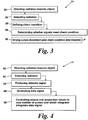
- FIG. 13 shows an embodiment of the invention, in which there is provided a system for generating an optimal pulse sequence and gain selection by analysis of the image data itself.
- programmable gain integrating amplifiers 130 are connected to each bank of detectors. Data from these detectors pass to a data acquisition unit 131 which outputs digital signals to an Image Processing Unit 132 which appends the new data to the image data to be displayed as an image on a monitor 133.
- a Decision Processing Unit reviews the new image and determines whether the new data is outside of the dynamic range of the integrating amplifier. If it is, the Decision Processing Unit 134 will cause the amplifier to continue to integrate and will instruct the radiation source to fire more pulses until the dynamic range required of the measurement has been achieved.
- the Decision Processing Unit may use a range of algorithms, but a simple threshold algorithm such as that shown in figure 14 is typically sufficient. If a signal is received below threshold 140, the Decision Processor will instruct the source to provide further pulses. More sophisticated algorithms will use methods such as image segmentation and connected component labelling to identify from one or more 2D image scans the extent of a volume projected into one or more subsequent 2D detected images and to automatically predict when the multiple pulse stream will be required.
- the radiation shielding can be designed around the low energy pulse requirements since for a very large fraction of time it is this radiation beam that is generated. For the small fraction of time that a high energy beam is required, the instantaneous dose will be somewhat higher. However, dose is calculated in a time averaged fashion and hence if the Decision Processor is restricted in the number of high energy pulses that it can emit (for example, no more than 5% of the time), then radiation dose can be kept to an acceptable level with very moderate radiation shielding requirements.
Description
- The present invention relates to scanning systems. It has particular application in scanning systems for cargo, but can also be used in scanners for other applications such as security and medical scanners.
- Conventional cargo inspection systems comprise a radiation source that irradiates with X-rays or gamma-rays through the object under inspection to a sensor array that may be in an arc shape or configured into an "L"-shaped array. Other forms of sensor array will be apparent to the skilled person.
- Often, such systems use a linear accelerator to produce X-rays or a radioactive source such as 137Cs or 60Co to produce gamma-rays.
- Linear accelerators are typically operated with beam energies of 2MV to 9MV where a 2MV beam is one that is generated by firing a 2 MeV electron beam at a target, producing a broad spectrum of X-ray energies up to a maximum of 2 MeV but with a typical 1/3 of peak energy. This high-energy X-ray beam can penetrate large objects such as full containers or complete trucks.
- Radioactive sources are often used in lower cost installations with a lower radiation penetration requirement. For example, they might be used for screening cars or smaller air-cargo type containers. 137Cs provides gamma rays at an energy of 662 keV (more or less equivalent to a 2 MV linear accelerator source) while 60Co produces gamma rays at an energy of around 1.2 MeV (more or less equivalent to a 4 MV linear accelerator source).
- Previously, linear accelerators have often been fabricated using low frequency S-band microwave energy sources. The waveguide used in the linear accelerator defines the overall size of the finished radiation source. Therefore, such sources are typically bulky and heavy since thick radiation shielding must be installed around the whole accelerating structure.
US6713773 B1 is an example of a prior art scanning system which controls the pulses of radiation based on a level of detected radiation which has passed through an object being scanned. -
US5909478 discloses a portable imaging system, wherein a user has the possibility to control the x-ray image acquisition duration, in order to improve the generated image. - The present invention provides a scanning system comprising a radiation source arranged to direct pulses of radiation towards an object, detection means arranged to detect the radiation, wherein the detection means includes a plurality of detector banks arranged to produce a detector signal in response to detection of the radiation, acquisition means comprising a plurality of programmable gain integrating amplifiers each connected to a bank of detectors arranged to generate a data signal from the detector signal, image processing means arranged to generate image data which defines images of the object from digital signals from the acquisition means, a decision processing means arranged to receive and review the image data and determine whether the detector signals are outside the dynamic range of the amplifiers, instruct the source to fire more pulses and control the acquisition means so as to vary the number of pulses over which the amplifiers integrate the detector signal until the dynamic range required is achieved thereby to vary the sensitivity of the system.
- The present invention also provides a method of scanning an object comprising directing pulses of radiation from a radiation source towards an object, detecting the radiation using radiation detection means comprising a plurality of detector banks, producing a detector signal in response to detection of the radiation, generating a data signal from the detector signal using acquisition means which comprises a plurality of programmable gain integrating amplifiers each connected to a bank of detectors, generating image data which defines images of the object using image processing means receiving digital data from the acquisition means, reviewing the image data and determining whether the detector signals are outside the dynamic range of the amplifiers, instructing the source to fire more pulses and controlling the acquisition means so as to vary the number of pulses over which the amplifiers integrate the detector signal until the dynamic range required is achieved thereby to vary the sensitivity of the system.
- The present invention is directed in part at the use of compact imaging sources for imaging of cargo items from small containers up to large trucks.
- A radioactive source is naturally compact and therefore of smallest possible weight given that the radiation shield must be located all around the radiation source. However, the radiation source may not be switched on and off, requiring a manual shutter for this purpose. Such a shutter may become stuck so posing a potential safety hazard. Further, the transportation of such sources can be problematic, particularly across national borders.
Linear accelerators are convenient but complex radiation sources in that they may be turned on and off simply using electronic means. When the power supply is disconnected, no radiation can be emitted at all. Transportation becomes more straightforward and they are intrinsically safer to operate.
In some embodiments of the present invention, a compact imaging source is built around a linear accelerator that operates at high frequency. High frequency results in low wavelength and so a more compact linear accelerator design is the result. Advantageously, an X-band linear accelerator may be used, or alternatively one with similarly high operating frequency. - To provide best imaging capability, the compact radiation source may be capable of operating in a number of modes.
- Embodiments of the present invention will now be described by way of example only with reference to the accompanying drawings, in which:
-
Figure 1 schematically shows a scanning system setup; -
Figure 2 schematically shows a scanning system according to another example; -
Figure 3 is a flowchart showing a method of scanning an object not within the scope of this invention; -
Figure 4 is a flowchart showing a method of scanning an object not comprising all steps of the invention; -
Figure 5 schematically shows two typical scanning system geometries; -
Figure 6 graphically represents the timing of pulses of radiation from a radiation source; -
Figure 7 graphically represents variation of pulse frequency with object velocity; -
Figure 8 graphically represents variable energy pulsed radiation; -
Figure 9 graphically represents different variable energy pulsed radiation; -
Figure 10 schematically shows a switching gain integrator circuit for processing detector signals; -
Figure 11 graphically represents collection and integration of detector data over several radiation pulses; -
Figure 12 schematically shows part of a scanning system; -
Figure 13 schematically shows part of a scanning system according to an embodiment of the invention; and -
Figure 14 graphically represents operation of a threshold check level within said embodiment of the invention. - Referring to
Figure 1 , ascanning system 10 comprises aradiation source 12 arranged to direct radiation towards anobject 14 to be scanned. Thesystem 10 also includes a detection means 16 arranged to detect the radiation. The radiation source comprises a linear accelerator of the type previously described or may be any other suitable source (for example, a different type of previously described radiation source). The detector means 16 comprises an L-shaped sensor array, which comprises a plurality of banks of detectors. In this example theobject 14 being scanned is a lorry. Thesystem 10 also comprises acontroller 18 which is arranged to control theradiation source 12 such that thesource 12 produces radiation in pulses. Thecontroller 18 is also arranged to define a check condition and to process signals from the detection means 16 in order to determine whether they meet the check condition. Thecontroller 18 varies the pulses of theradiation source 12 dependent upon whether or not the signals from the detection means meet the check condition. - Referring to
Figure 2 , ascanning system 20 comprises aradiation source 22 arranged to direct radiation towards anobject 24. Thesystem 20 also includes detection means 26 in the form of a detector which produces a detector signal in response to detection of radiation in a similar manner to the embodiment ofFigure 1 . Thesystem 20 also includes acquisition means 30 comprising an integrator which is arranged to generate a data signal from the signal which is received from the detector (the detector signal). Thesystem 20 also includes control means 28 in communication with both thesource 22 and the acquisition means 30. The control means 28 is arranged to control thesource 20 and the acquisition means 30 to vary the number of pulses over which the integrator integrates the detector signal - thus allowing variation of the sensitivity of thesystem 20. Advantageously, if it is deemed necessary by thecontroller 28, the integrator can be used to generate a data signal which comprises a detector signal relating to more than one pulse of radiation. This may be particularly useful in situations where enough radiation is not detected from a single pulse. The control means 28 controls thesource 22 to vary the frequency of the pulses in order to vary the number of pulses in which the integrator integrates the detector signal, or the number of pulses over which the integrator integrates the detector signal is varied by varying the time over which the integrator integrates the detector signal. The control means 18 is arranged to generate image data which defines images of theobject 14 from some signals from the detection means. - Two typical imaging geometries are shown in
figure 5. Figure 5 (a) shows asystem 51 configured with an "L"-shapedsensor array 52 with acompact radiation source 53 to the left whilefigure 5 (b) shows an arc-shapedsensor array 54 with thecompact source 53 to the left. - A compact linear-accelerator source will typically run with a pulse configuration as shown in
figure 6 . Here, each pulse will typically have a pulse width of a few microseconds (1 - 10 µs is typical) with a pulse repetition frequency that is often in therange 50 to 200 Hz. The compact radiation source is capable of pulse frequency modulation such that the timing of each pulse from the linear accelerator is timed to match the velocity of the object under inspection as it passes through the slice-like radiation beam. A suitable pulse frequency modulation example is shown infigure 7. Figure 7(a) represents the object velocity, whilstFigure 7(b) shows the pulse timing. The pulse frequency increases as the object velocity increases. An object of the imaging system is to identify threat materials within the object under inspection. This may be achieved using an operator (such as a human operator) to look for objects within this image. However, it is also possible to provide some materials discrimination by using a variable energy radiation beam. As shown infigure 8 , it is possible to pulse the energy of the linear accelerator source to alternate energies, for example a high energy of 6MV and a low energy of 2 MV. In this case, the radiation energy transmitted by the object will be different for the high and low energy pulses (since each material in the beam has a characteristic and energy-varying radiation absorbance). Such variation in energy of the pulses is incorporated with pulse frequency modulation to provide high quality scanning of the object under inspection. An objective of the compact cargo inspection system is to minimise the size and weight of the radiation source. The higher the energy of operation of the radiation source, the larger and heavier the source becomes. It can therefore be advantageous to operate the radiation source at the lowest possible energy. However, in some situations, the energy of the radiation source is too low to provide effective penetration through the object under inspection. In this case, the cargo item can be treated as not being properly inspected. Therefore, to address this problem, a pulse sequence as shown infigure 9 is adopted. Here, the majority of pulses are emitted at low energy (say 2 MV). The detector signals are recorded and checked to see if sufficient object penetration has been measured. If not, the radiation source is instructed to emit a high energy pulse at say 6MV (marked (a) infigure 9 ) in order to provide a set of data with the required penetration. Now, it is possible to resolve the majority of dark alarms (a dark alarm is defined as occurring where insufficient penetration was recorded by the low energy pulse) without providing excessive dose at the external surface of the unit. In some situations (marked (b) infigure 9 ), it may be necessary to provide several consecutive high energy pulses to get sufficient signal for the transmission measurement. - Typically, the high energy pulse will contain more X-ray photons than a low energy pulse. This can place severe demands on the dynamic range and noise of the front-end readout electronics. As shown in
figure 10 , a switching gain front end integrator circuit is provided whose operation is linked to the pulse generator for the linear accelerator. In normal operation with low energy pulses from the radiation source, the Gain switch is open and the value of C1 alone determines the gain. For example, if C1 = 3pF, then the output of the integrator with be 1V for a 3pC input charge from the front end photodiode. In high-energy mode the Gain switch is closed and now the total capacitance is equal to C1 + C2. For example, if C2 = 9pF, then the output of the integrator will be 0.25V for a 3pC input charge from the front-end photodiode.Figure 11 shows how the integrator may be held in integrating mode over several radiation pulses. Now, it is possible to acquire a burst containing multiple radiation pulses so that regions in which previously there was a dark alarm can now be resolved with measurable signal. Ideally, the base pulse frequency of the imaging system will be maintained (at say 50 Hz) with the additional pulses being fired within the normal beam off time (say at 400 Hz pulse repetition frequency). In this way, the normal imaging quality is not compromised by the additional measurement.Figure 11 shows the Gain switch being turned to low gain mode during the extra pulse measurement period although it would also be possible to operate in the standard high gain mode for extra sensitivity. -
Figure 12 s hows that the gain switch may be operated differently on different detector banks or groups (or different detector portions provided on the same detector) in order to optimise the dynamic range of the X-ray detector system. In this case six detector banks are shown labelled 1-6. -
Figure 13 shows an embodiment of the invention, in which there is provided a system for generating an optimal pulse sequence and gain selection by analysis of the image data itself. Here, programmablegain integrating amplifiers 130 are connected to each bank of detectors. Data from these detectors pass to adata acquisition unit 131 which outputs digital signals to anImage Processing Unit 132 which appends the new data to the image data to be displayed as an image on amonitor 133. A Decision Processing Unit reviews the new image and determines whether the new data is outside of the dynamic range of the integrating amplifier. If it is, theDecision Processing Unit 134 will cause the amplifier to continue to integrate and will instruct the radiation source to fire more pulses until the dynamic range required of the measurement has been achieved. - The Decision Processing Unit may use a range of algorithms, but a simple threshold algorithm such as that shown in
figure 14 is typically sufficient. If a signal is received belowthreshold 140, the Decision Processor will instruct the source to provide further pulses. More sophisticated algorithms will use methods such as image segmentation and connected component labelling to identify from one or more 2D image scans the extent of a volume projected into one or more subsequent 2D detected images and to automatically predict when the multiple pulse stream will be required. - It is noted that the radiation shielding can be designed around the low energy pulse requirements since for a very large fraction of time it is this radiation beam that is generated. For the small fraction of time that a high energy beam is required, the instantaneous dose will be somewhat higher. However, dose is calculated in a time averaged fashion and hence if the Decision Processor is restricted in the number of high energy pulses that it can emit (for example, no more than 5% of the time), then radiation dose can be kept to an acceptable level with very moderate radiation shielding requirements.
- Various modifications may be made to the present invention without departing from its scope.
Claims (5)
- A scanning system (10, 20, 51) comprising a radiation source (12, 22, 53) arranged to direct pulses of radiation towards an object (14, 24), detection means (16, 26, 52, 54) arranged to detect the radiation, wherein the detection means includes a plurality of detector banks (1-6) arranged to produce a detector signal in response to detection of the radiation, acquisition means (131) comprising a plurality of programmable gain integrating amplifiers (130) each connected to a bank of detectors arranged to generate a data signal from the detector signal, image processing means (132) arranged to generate image data which defines images of the object (14, 24) from digital signals from the acquisition means (131), a decision processing means (134) arranged to receive and review the image data and determine whether the detector signals are outside the dynamic range of the amplifiers (130), instruct the source (12, 22, 53) to fire more pulses and control the acquisition means (131) so as to vary the number of pulses over which the amplifiers (130) integrate the detector signal until the dynamic range required is achieved thereby to vary the sensitivity of the system.
- A system according to claim 1 wherein the decision processing means (134) is arranged to vary said number of pulses by varying the frequency of the pulses.
- A system according to claim 1 wherein the decision processing means (134) is arranged to vary said number of pulses by varying the time over which the amplifiers (130) integrate the detector signal.
- A system according to any foregoing claim wherein the radiation source (12, 22, 53) comprises an accelerator arranged to accelerate particles towards a target to generate the radiation.
- A method of scanning an object comprising directing pulses of radiation from a radiation source (12, 22, 53) towards an object (14, 24), detecting the radiation using radiation detection means (16, 26, 52, 54) comprising a plurality of detector banks (1-6), producing a detector signal in response to detection of the radiation, generating a data signal from the detector signal using acquisition means (131) which comprises a plurality of programmable gain integrating amplifiers (130) each connected to a bank of detectors, generating image data which defines images of the object using image processing means (132) receiving digital signals from said acquisition means (131), reviewing the image data and determining whether the detector signals are outside the dynamic range (140) of the amplifiers (130), instructing the source (12, 22, 53) to fire more pulses and controlling the acquisition means (131) so as to vary the number of pulses over which the amplifiers (130) integrate the detector signal until the dynamic range (140) required is achieved thereby to vary the sensitivity of the system.
Priority Applications (2)
| Application Number | Priority Date | Filing Date | Title |
|---|---|---|---|
| EP18165979.8A EP3364219A3 (en) | 2007-08-31 | 2008-08-29 | Scanning systems |
| PL08788456T PL2188652T3 (en) | 2007-08-31 | 2008-08-29 | Scanning systems for security and medical scanners having means to control the radiation source |
Applications Claiming Priority (3)
| Application Number | Priority Date | Filing Date | Title |
|---|---|---|---|
| US96953507P | 2007-08-31 | 2007-08-31 | |
| GBGB0803646.9A GB0803646D0 (en) | 2008-02-28 | 2008-02-28 | Scanning systems |
| PCT/GB2008/002897 WO2009027667A2 (en) | 2007-08-31 | 2008-08-29 | Scanning systems for security and medical scanners having means to control the radiation source |
Related Child Applications (2)
| Application Number | Title | Priority Date | Filing Date |
|---|---|---|---|
| EP18165979.8A Division EP3364219A3 (en) | 2007-08-31 | 2008-08-29 | Scanning systems |
| EP18165979.8A Division-Into EP3364219A3 (en) | 2007-08-31 | 2008-08-29 | Scanning systems |
Publications (2)
| Publication Number | Publication Date |
|---|---|
| EP2188652A2 EP2188652A2 (en) | 2010-05-26 |
| EP2188652B1 true EP2188652B1 (en) | 2018-05-16 |
Family
ID=39284707
Family Applications (2)
| Application Number | Title | Priority Date | Filing Date |
|---|---|---|---|
| EP18165979.8A Withdrawn EP3364219A3 (en) | 2007-08-31 | 2008-08-29 | Scanning systems |
| EP08788456.5A Active EP2188652B1 (en) | 2007-08-31 | 2008-08-29 | Scanning systems for security and medical scanners having means to control the radiation source |
Family Applications Before (1)
| Application Number | Title | Priority Date | Filing Date |
|---|---|---|---|
| EP18165979.8A Withdrawn EP3364219A3 (en) | 2007-08-31 | 2008-08-29 | Scanning systems |
Country Status (5)
| Country | Link |
|---|---|
| EP (2) | EP3364219A3 (en) |
| CN (1) | CN101971055B (en) |
| GB (1) | GB0803646D0 (en) |
| PL (1) | PL2188652T3 (en) |
| WO (1) | WO2009027667A2 (en) |
Families Citing this family (29)
| Publication number | Priority date | Publication date | Assignee | Title |
|---|---|---|---|---|
| US7963695B2 (en) | 2002-07-23 | 2011-06-21 | Rapiscan Systems, Inc. | Rotatable boom cargo scanning system |
| US9958569B2 (en) | 2002-07-23 | 2018-05-01 | Rapiscan Systems, Inc. | Mobile imaging system and method for detection of contraband |
| US8503605B2 (en) | 2002-07-23 | 2013-08-06 | Rapiscan Systems, Inc. | Four sided imaging system and method for detection of contraband |
| US8275091B2 (en) | 2002-07-23 | 2012-09-25 | Rapiscan Systems, Inc. | Compact mobile cargo scanning system |
| US6928141B2 (en) | 2003-06-20 | 2005-08-09 | Rapiscan, Inc. | Relocatable X-ray imaging system and method for inspecting commercial vehicles and cargo containers |
| US7471764B2 (en) | 2005-04-15 | 2008-12-30 | Rapiscan Security Products, Inc. | X-ray imaging system having improved weather resistance |
| US7526064B2 (en) | 2006-05-05 | 2009-04-28 | Rapiscan Security Products, Inc. | Multiple pass cargo inspection system |
| GB0803641D0 (en) | 2008-02-28 | 2008-04-02 | Rapiscan Security Products Inc | Scanning systems |
| GB0803642D0 (en) | 2008-02-28 | 2008-04-02 | Rapiscan Security Products Inc | Drive-through scanning systems |
| GB0809110D0 (en) | 2008-05-20 | 2008-06-25 | Rapiscan Security Products Inc | Gantry scanner systems |
| EP3287773B1 (en) | 2008-08-11 | 2021-03-03 | Rapiscan Laboratories, Inc. | Systems and methods for using an intensity -modulated x-ray source |
| GB201001738D0 (en) | 2010-02-03 | 2010-03-24 | Rapiscan Lab Inc | Scanning systems |
| GB201001736D0 (en) | 2010-02-03 | 2010-03-24 | Rapiscan Security Products Inc | Scanning systems |
| PL2673660T3 (en) | 2011-02-08 | 2018-01-31 | Rapiscan Systems Inc | Covert surveillance using multi-modality sensing |
| US9218933B2 (en) | 2011-06-09 | 2015-12-22 | Rapidscan Systems, Inc. | Low-dose radiographic imaging system |
| US9224573B2 (en) | 2011-06-09 | 2015-12-29 | Rapiscan Systems, Inc. | System and method for X-ray source weight reduction |
| CN104170051B (en) | 2012-02-03 | 2017-05-31 | 拉皮斯坎系统股份有限公司 | Combination scattering and the imaging multiple views system of transmission |
| US9274065B2 (en) | 2012-02-08 | 2016-03-01 | Rapiscan Systems, Inc. | High-speed security inspection system |
| US10670740B2 (en) | 2012-02-14 | 2020-06-02 | American Science And Engineering, Inc. | Spectral discrimination using wavelength-shifting fiber-coupled scintillation detectors |
| KR102167245B1 (en) | 2013-01-31 | 2020-10-19 | 라피스캔 시스템스, 인코포레이티드 | Portable security inspection system |
| US9622333B2 (en) | 2014-02-27 | 2017-04-11 | Etm Electromatic, Inc | Linear accelerator system with stable interleaved and intermittent pulsing |
| GB2554566B (en) | 2015-03-20 | 2021-06-02 | Rapiscan Systems Inc | Hand-held portable backscatter inspection system |
| GB2558505B (en) * | 2015-10-21 | 2021-05-12 | Rapiscan Systems Inc | High dynamic range radiographic imaging system |
| GB2567115B (en) | 2016-07-14 | 2022-08-10 | Rapiscan Systems Inc | Systems and methods for improving penetration of radiographic scanners |
| WO2019245636A1 (en) | 2018-06-20 | 2019-12-26 | American Science And Engineering, Inc. | Wavelength-shifting sheet-coupled scintillation detectors |
| GB2594449B (en) * | 2020-04-20 | 2023-07-19 | Smiths Detection France S A S | Pulse frequency adjustment |
| US11175245B1 (en) | 2020-06-15 | 2021-11-16 | American Science And Engineering, Inc. | Scatter X-ray imaging with adaptive scanning beam intensity |
| US11340361B1 (en) | 2020-11-23 | 2022-05-24 | American Science And Engineering, Inc. | Wireless transmission detector panel for an X-ray scanner |
| CN113281821B (en) * | 2021-07-09 | 2023-10-13 | 同方威视技术股份有限公司 | Inspection system and method |
Family Cites Families (8)
| Publication number | Priority date | Publication date | Assignee | Title |
|---|---|---|---|---|
| US4703496A (en) * | 1985-12-30 | 1987-10-27 | General Electric Company | Automatic x-ray image brightness control |
| US5119409A (en) * | 1990-12-28 | 1992-06-02 | Fischer Imaging Corporation | Dynamic pulse control for fluoroscopy |
| US5608774A (en) * | 1995-06-23 | 1997-03-04 | Science Applications International Corporation | Portable, digital X-ray apparatus for producing, storing, and displaying electronic radioscopic images |
| US6713773B1 (en) * | 1999-10-07 | 2004-03-30 | Mitec, Inc. | Irradiation system and method |
| US20050117683A1 (en) * | 2000-02-10 | 2005-06-02 | Andrey Mishin | Multiple energy x-ray source for security applications |
| US6954515B2 (en) * | 2003-04-25 | 2005-10-11 | Varian Medical Systems, Inc., | Radiation sources and radiation scanning systems with improved uniformity of radiation intensity |
| WO2006053279A2 (en) * | 2004-11-12 | 2006-05-18 | Scantech Holdings, Llc | Non-intrusive container inspection system using forward-scattered radiation |
| DE102005006895B4 (en) * | 2005-02-15 | 2010-11-18 | Siemens Ag | X-ray diagnostic device and method for its regulation |
-
2008
- 2008-02-28 GB GBGB0803646.9A patent/GB0803646D0/en not_active Ceased
- 2008-08-29 EP EP18165979.8A patent/EP3364219A3/en not_active Withdrawn
- 2008-08-29 CN CN200880114130.0A patent/CN101971055B/en active Active
- 2008-08-29 WO PCT/GB2008/002897 patent/WO2009027667A2/en active Application Filing
- 2008-08-29 PL PL08788456T patent/PL2188652T3/en unknown
- 2008-08-29 EP EP08788456.5A patent/EP2188652B1/en active Active
Non-Patent Citations (1)
| Title |
|---|
| None * |
Also Published As
| Publication number | Publication date |
|---|---|
| WO2009027667A2 (en) | 2009-03-05 |
| EP3364219A2 (en) | 2018-08-22 |
| WO2009027667A3 (en) | 2009-06-25 |
| GB0803646D0 (en) | 2008-04-02 |
| EP2188652A2 (en) | 2010-05-26 |
| CN101971055B (en) | 2015-02-04 |
| CN101971055A (en) | 2011-02-09 |
| EP3364219A3 (en) | 2019-01-30 |
| PL2188652T3 (en) | 2018-09-28 |
Similar Documents
| Publication | Publication Date | Title |
|---|---|---|
| EP2188652B1 (en) | Scanning systems for security and medical scanners having means to control the radiation source | |
| US20240118449A1 (en) | Covert Surveillance Using Multi-Modality Sensing | |
| US8457274B2 (en) | System and methods for intrapulse multi-energy and adaptive multi-energy X-ray cargo inspection | |
| CA2301160C (en) | Material discrimination using single-energy x-ray imaging system | |
| US3808444A (en) | X-ray contrast detection system | |
| US9348040B2 (en) | Adaptive scanning in an imaging system | |
| US5838758A (en) | Device and method for inspection of baggage and other objects | |
| US5022062A (en) | Automatic threat detection based on illumination by penetrating radiant energy using histogram processing | |
| US8993970B2 (en) | Photomultiplier and detection systems | |
| US7453987B1 (en) | Method and system for high energy, low radiation power X-ray imaging of the contents of a target | |
| EP1882929B1 (en) | A detection system and detection method based on pulsed energetic particles | |
| US20030147484A1 (en) | Method for detecting an explosive in an object under investigation | |
| US20110243382A1 (en) | X-Ray Inspection System and Method | |
| JP2008164429A (en) | X-ray sensor for x-ray inspection apparatus | |
| US10197700B2 (en) | Method for autonomous self-blanking by radiation portal monitors to minimize the interference from pulsed X-rays radiation | |
| RU2095795C1 (en) | X-ray method for detection of material using its atomic number | |
| GB2242520A (en) | Explosives detector | |
| Arodzero et al. | MEBCIS: Multi-energy betatron-based cargo inspection system | |
| Lee et al. | Development of Dual Energy Container Inspection System for Harbor Security in KAERI | |
| Chalmers | Radioactive threat detection using scintillant-based detectors | |
| IL116600A (en) | Energy dispersive system for detecting specific atomic elements |
Legal Events
| Date | Code | Title | Description |
|---|---|---|---|
| PUAI | Public reference made under article 153(3) epc to a published international application that has entered the european phase |
Free format text: ORIGINAL CODE: 0009012 |
|
| 17P | Request for examination filed |
Effective date: 20100317 |
|
| AK | Designated contracting states |
Kind code of ref document: A2 Designated state(s): AT BE BG CH CY CZ DE DK EE ES FI FR GB GR HR HU IE IS IT LI LT LU LV MC MT NL NO PL PT RO SE SI SK TR |
|
| AX | Request for extension of the european patent |
Extension state: AL BA MK RS |
|
| RAP1 | Party data changed (applicant data changed or rights of an application transferred) |
Owner name: RAPISCAN SYSTEMS, INC. |
|
| DAX | Request for extension of the european patent (deleted) | ||
| 17Q | First examination report despatched |
Effective date: 20140725 |
|
| GRAP | Despatch of communication of intention to grant a patent |
Free format text: ORIGINAL CODE: EPIDOSNIGR1 |
|
| STAA | Information on the status of an ep patent application or granted ep patent |
Free format text: STATUS: GRANT OF PATENT IS INTENDED |
|
| INTG | Intention to grant announced |
Effective date: 20171124 |
|
| GRAS | Grant fee paid |
Free format text: ORIGINAL CODE: EPIDOSNIGR3 |
|
| GRAA | (expected) grant |
Free format text: ORIGINAL CODE: 0009210 |
|
| STAA | Information on the status of an ep patent application or granted ep patent |
Free format text: STATUS: THE PATENT HAS BEEN GRANTED |
|
| RAP1 | Party data changed (applicant data changed or rights of an application transferred) |
Owner name: RAPISCAN SYSTEMS, INC. |
|
| AK | Designated contracting states |
Kind code of ref document: B1 Designated state(s): AT BE BG CH CY CZ DE DK EE ES FI FR GB GR HR HU IE IS IT LI LT LU LV MC MT NL NO PL PT RO SE SI SK TR |
|
| REG | Reference to a national code |
Ref country code: GB Ref legal event code: FG4D |
|
| REG | Reference to a national code |
Ref country code: CH Ref legal event code: EP |
|
| REG | Reference to a national code |
Ref country code: IE Ref legal event code: FG4D |
|
| REG | Reference to a national code |
Ref country code: DE Ref legal event code: R096 Ref document number: 602008055282 Country of ref document: DE |
|
| REG | Reference to a national code |
Ref country code: AT Ref legal event code: REF Ref document number: 1000074 Country of ref document: AT Kind code of ref document: T Effective date: 20180615 |
|
| REG | Reference to a national code |
Ref country code: FR Ref legal event code: PLFP Year of fee payment: 11 |
|
| REG | Reference to a national code |
Ref country code: NL Ref legal event code: MP Effective date: 20180516 |
|
| REG | Reference to a national code |
Ref country code: LT Ref legal event code: MG4D |
|
| PG25 | Lapsed in a contracting state [announced via postgrant information from national office to epo] |
Ref country code: BG Free format text: LAPSE BECAUSE OF FAILURE TO SUBMIT A TRANSLATION OF THE DESCRIPTION OR TO PAY THE FEE WITHIN THE PRESCRIBED TIME-LIMIT Effective date: 20180816 Ref country code: FI Free format text: LAPSE BECAUSE OF FAILURE TO SUBMIT A TRANSLATION OF THE DESCRIPTION OR TO PAY THE FEE WITHIN THE PRESCRIBED TIME-LIMIT Effective date: 20180516 Ref country code: NO Free format text: LAPSE BECAUSE OF FAILURE TO SUBMIT A TRANSLATION OF THE DESCRIPTION OR TO PAY THE FEE WITHIN THE PRESCRIBED TIME-LIMIT Effective date: 20180816 Ref country code: SE Free format text: LAPSE BECAUSE OF FAILURE TO SUBMIT A TRANSLATION OF THE DESCRIPTION OR TO PAY THE FEE WITHIN THE PRESCRIBED TIME-LIMIT Effective date: 20180516 Ref country code: LT Free format text: LAPSE BECAUSE OF FAILURE TO SUBMIT A TRANSLATION OF THE DESCRIPTION OR TO PAY THE FEE WITHIN THE PRESCRIBED TIME-LIMIT Effective date: 20180516 Ref country code: ES Free format text: LAPSE BECAUSE OF FAILURE TO SUBMIT A TRANSLATION OF THE DESCRIPTION OR TO PAY THE FEE WITHIN THE PRESCRIBED TIME-LIMIT Effective date: 20180516 |
|
| PG25 | Lapsed in a contracting state [announced via postgrant information from national office to epo] |
Ref country code: HR Free format text: LAPSE BECAUSE OF FAILURE TO SUBMIT A TRANSLATION OF THE DESCRIPTION OR TO PAY THE FEE WITHIN THE PRESCRIBED TIME-LIMIT Effective date: 20180516 Ref country code: NL Free format text: LAPSE BECAUSE OF FAILURE TO SUBMIT A TRANSLATION OF THE DESCRIPTION OR TO PAY THE FEE WITHIN THE PRESCRIBED TIME-LIMIT Effective date: 20180516 Ref country code: GR Free format text: LAPSE BECAUSE OF FAILURE TO SUBMIT A TRANSLATION OF THE DESCRIPTION OR TO PAY THE FEE WITHIN THE PRESCRIBED TIME-LIMIT Effective date: 20180817 Ref country code: LV Free format text: LAPSE BECAUSE OF FAILURE TO SUBMIT A TRANSLATION OF THE DESCRIPTION OR TO PAY THE FEE WITHIN THE PRESCRIBED TIME-LIMIT Effective date: 20180516 |
|
| REG | Reference to a national code |
Ref country code: AT Ref legal event code: MK05 Ref document number: 1000074 Country of ref document: AT Kind code of ref document: T Effective date: 20180516 |
|
| PG25 | Lapsed in a contracting state [announced via postgrant information from national office to epo] |
Ref country code: RO Free format text: LAPSE BECAUSE OF FAILURE TO SUBMIT A TRANSLATION OF THE DESCRIPTION OR TO PAY THE FEE WITHIN THE PRESCRIBED TIME-LIMIT Effective date: 20180516 Ref country code: SK Free format text: LAPSE BECAUSE OF FAILURE TO SUBMIT A TRANSLATION OF THE DESCRIPTION OR TO PAY THE FEE WITHIN THE PRESCRIBED TIME-LIMIT Effective date: 20180516 Ref country code: EE Free format text: LAPSE BECAUSE OF FAILURE TO SUBMIT A TRANSLATION OF THE DESCRIPTION OR TO PAY THE FEE WITHIN THE PRESCRIBED TIME-LIMIT Effective date: 20180516 Ref country code: AT Free format text: LAPSE BECAUSE OF FAILURE TO SUBMIT A TRANSLATION OF THE DESCRIPTION OR TO PAY THE FEE WITHIN THE PRESCRIBED TIME-LIMIT Effective date: 20180516 Ref country code: DK Free format text: LAPSE BECAUSE OF FAILURE TO SUBMIT A TRANSLATION OF THE DESCRIPTION OR TO PAY THE FEE WITHIN THE PRESCRIBED TIME-LIMIT Effective date: 20180516 Ref country code: CZ Free format text: LAPSE BECAUSE OF FAILURE TO SUBMIT A TRANSLATION OF THE DESCRIPTION OR TO PAY THE FEE WITHIN THE PRESCRIBED TIME-LIMIT Effective date: 20180516 |
|
| REG | Reference to a national code |
Ref country code: DE Ref legal event code: R097 Ref document number: 602008055282 Country of ref document: DE |
|
| PG25 | Lapsed in a contracting state [announced via postgrant information from national office to epo] |
Ref country code: IT Free format text: LAPSE BECAUSE OF FAILURE TO SUBMIT A TRANSLATION OF THE DESCRIPTION OR TO PAY THE FEE WITHIN THE PRESCRIBED TIME-LIMIT Effective date: 20180516 |
|
| PLBE | No opposition filed within time limit |
Free format text: ORIGINAL CODE: 0009261 |
|
| STAA | Information on the status of an ep patent application or granted ep patent |
Free format text: STATUS: NO OPPOSITION FILED WITHIN TIME LIMIT |
|
| PG25 | Lapsed in a contracting state [announced via postgrant information from national office to epo] |
Ref country code: MC Free format text: LAPSE BECAUSE OF FAILURE TO SUBMIT A TRANSLATION OF THE DESCRIPTION OR TO PAY THE FEE WITHIN THE PRESCRIBED TIME-LIMIT Effective date: 20180516 |
|
| REG | Reference to a national code |
Ref country code: CH Ref legal event code: PL |
|
| 26N | No opposition filed |
Effective date: 20190219 |
|
| PG25 | Lapsed in a contracting state [announced via postgrant information from national office to epo] |
Ref country code: LU Free format text: LAPSE BECAUSE OF NON-PAYMENT OF DUE FEES Effective date: 20180829 Ref country code: LI Free format text: LAPSE BECAUSE OF NON-PAYMENT OF DUE FEES Effective date: 20180831 Ref country code: CH Free format text: LAPSE BECAUSE OF NON-PAYMENT OF DUE FEES Effective date: 20180831 |
|
| REG | Reference to a national code |
Ref country code: BE Ref legal event code: MM Effective date: 20180831 |
|
| PG25 | Lapsed in a contracting state [announced via postgrant information from national office to epo] |
Ref country code: SI Free format text: LAPSE BECAUSE OF FAILURE TO SUBMIT A TRANSLATION OF THE DESCRIPTION OR TO PAY THE FEE WITHIN THE PRESCRIBED TIME-LIMIT Effective date: 20180516 |
|
| PG25 | Lapsed in a contracting state [announced via postgrant information from national office to epo] |
Ref country code: BE Free format text: LAPSE BECAUSE OF NON-PAYMENT OF DUE FEES Effective date: 20180831 |
|
| PG25 | Lapsed in a contracting state [announced via postgrant information from national office to epo] |
Ref country code: MT Free format text: LAPSE BECAUSE OF NON-PAYMENT OF DUE FEES Effective date: 20180829 |
|
| PG25 | Lapsed in a contracting state [announced via postgrant information from national office to epo] |
Ref country code: TR Free format text: LAPSE BECAUSE OF FAILURE TO SUBMIT A TRANSLATION OF THE DESCRIPTION OR TO PAY THE FEE WITHIN THE PRESCRIBED TIME-LIMIT Effective date: 20180516 |
|
| PG25 | Lapsed in a contracting state [announced via postgrant information from national office to epo] |
Ref country code: PT Free format text: LAPSE BECAUSE OF FAILURE TO SUBMIT A TRANSLATION OF THE DESCRIPTION OR TO PAY THE FEE WITHIN THE PRESCRIBED TIME-LIMIT Effective date: 20180516 Ref country code: HU Free format text: LAPSE BECAUSE OF FAILURE TO SUBMIT A TRANSLATION OF THE DESCRIPTION OR TO PAY THE FEE WITHIN THE PRESCRIBED TIME-LIMIT; INVALID AB INITIO Effective date: 20080829 |
|
| PG25 | Lapsed in a contracting state [announced via postgrant information from national office to epo] |
Ref country code: CY Free format text: LAPSE BECAUSE OF FAILURE TO SUBMIT A TRANSLATION OF THE DESCRIPTION OR TO PAY THE FEE WITHIN THE PRESCRIBED TIME-LIMIT Effective date: 20180516 Ref country code: IE Free format text: LAPSE BECAUSE OF NON-PAYMENT OF DUE FEES Effective date: 20180829 |
|
| PG25 | Lapsed in a contracting state [announced via postgrant information from national office to epo] |
Ref country code: IS Free format text: LAPSE BECAUSE OF FAILURE TO SUBMIT A TRANSLATION OF THE DESCRIPTION OR TO PAY THE FEE WITHIN THE PRESCRIBED TIME-LIMIT Effective date: 20180916 |
|
| PGFP | Annual fee paid to national office [announced via postgrant information from national office to epo] |
Ref country code: GB Payment date: 20230830 Year of fee payment: 16 |
|
| PGFP | Annual fee paid to national office [announced via postgrant information from national office to epo] |
Ref country code: PL Payment date: 20230828 Year of fee payment: 16 Ref country code: FR Payment date: 20230829 Year of fee payment: 16 Ref country code: DE Payment date: 20230829 Year of fee payment: 16 |