EP2187619A1 - Improved method, system and apparatus for synchronizing signals - Google Patents
Improved method, system and apparatus for synchronizing signals Download PDFInfo
- Publication number
- EP2187619A1 EP2187619A1 EP08019378A EP08019378A EP2187619A1 EP 2187619 A1 EP2187619 A1 EP 2187619A1 EP 08019378 A EP08019378 A EP 08019378A EP 08019378 A EP08019378 A EP 08019378A EP 2187619 A1 EP2187619 A1 EP 2187619A1
- Authority
- EP
- European Patent Office
- Prior art keywords
- time
- network
- slave
- information
- master
- Prior art date
- Legal status (The legal status is an assumption and is not a legal conclusion. Google has not performed a legal analysis and makes no representation as to the accuracy of the status listed.)
- Ceased
Links
Images
Classifications
-
- H—ELECTRICITY
- H04—ELECTRIC COMMUNICATION TECHNIQUE
- H04N—PICTORIAL COMMUNICATION, e.g. TELEVISION
- H04N5/00—Details of television systems
- H04N5/04—Synchronising
-
- H—ELECTRICITY
- H04—ELECTRIC COMMUNICATION TECHNIQUE
- H04N—PICTORIAL COMMUNICATION, e.g. TELEVISION
- H04N5/00—Details of television systems
- H04N5/04—Synchronising
- H04N5/06—Generation of synchronising signals
- H04N5/067—Arrangements or circuits at the transmitter end
- H04N5/073—Arrangements or circuits at the transmitter end for mutually locking plural sources of synchronising signals, e.g. studios or relay stations
-
- G—PHYSICS
- G06—COMPUTING OR CALCULATING; COUNTING
- G06F—ELECTRIC DIGITAL DATA PROCESSING
- G06F1/00—Details not covered by groups G06F3/00 - G06F13/00 and G06F21/00
- G06F1/04—Generating or distributing clock signals or signals derived directly therefrom
-
- G—PHYSICS
- G06—COMPUTING OR CALCULATING; COUNTING
- G06F—ELECTRIC DIGITAL DATA PROCESSING
- G06F1/00—Details not covered by groups G06F3/00 - G06F13/00 and G06F21/00
- G06F1/04—Generating or distributing clock signals or signals derived directly therefrom
- G06F1/12—Synchronisation of different clock signals provided by a plurality of clock generators
-
- H—ELECTRICITY
- H04—ELECTRIC COMMUNICATION TECHNIQUE
- H04J—MULTIPLEX COMMUNICATION
- H04J3/00—Time-division multiplex systems
- H04J3/02—Details
- H04J3/06—Synchronising arrangements
-
- H—ELECTRICITY
- H04—ELECTRIC COMMUNICATION TECHNIQUE
- H04J—MULTIPLEX COMMUNICATION
- H04J3/00—Time-division multiplex systems
- H04J3/02—Details
- H04J3/06—Synchronising arrangements
- H04J3/0635—Clock or time synchronisation in a network
- H04J3/0682—Clock or time synchronisation in a network by delay compensation, e.g. by compensation of propagation delay or variations thereof, by ranging
Definitions
- the method, system and apparatus described herein relate to the processing of signals.
- they relate to synchronizing unrelated reference signals associated with information signals (e.g. video or audio signals) originating from two or more sources, possibly at geographically different locations and/or in different formats.
- information signals e.g. video or audio signals
- US Patent 6,191,821 Korean Patent 6,191,821 (Kupnicki ).
- FR 2007/050918 refers to transmitting a synchronizing signal in a packet network having two or more station.
- Image cues are extracted from a synchronizing signal.
- a first counter is initialized based on the image cues.
- a program clock reference counter is initialized every second or higher zero crossing of the first counter.
- the program clock reference counter samples all the Tech periods. Tech is derived from a time base synchronized on all the network stations. Packets containing the samples are transmitted in the network.
- the synchronizing signal is a Genlock signal.
- the time base synchronized on all the network stations is an IEC 1588 time base.
- FR 2007/050919 refers to a secure mechanism for transmission of a synchronizing signal in a packet network.
- a device transmits packets in a packet communication network comprising two or more stations.
- the device has a signal receiver and can control a counter using the received signal.
- the counter samples every Tech periods. Tech is derived from a time base synchronized on all the stations of the network.
- An incremental value predicting at least a next sampled value of the counter is calculated. Sampled values and associated incremental values are transmitted in packets.
- the time base synchronized on all the network stations is an IEC 1588 time base.
- the received signal is a Genlock (synchronization lock) signal.
- the communication network is an IP (Internet Protocol) network.
- FR 2007/050914 refers to generating and operating a double temporal descriptor for transmitting a synchronizing signal in a packet network.
- Packets are transmitted in a packet communication network comprising two or more stations.
- a signal receiver is adapted to derive a frequency and a phase from a received signal.
- a master counter is provided and initialized by the derived frequency and phase.
- a sampling device samples the value of the master counter at regular intervals. From a sampled value of the master counter, a first temporal descriptor is generated.
- a second counter is synchronized on all network stations at the same instant when the sampling of the master counter occurs.
- a second temporal descriptor is generated from a sampled value of the second counter.
- the two temporal descriptors are jointly transmitted in the network.
- the packet communication network is an IP network.
- the second counter is synchronized on all the network stations by means of the IEC 1588 standard.
- the received signal is a Genlock signal.
- the present method and apparatus allows the synchronization of two or more video / audio / multimedia sources, such as, but not limited to video cameras, television cameras and videotape machines. Without this synchronization, switching between the sources will e.g. result in a momentary loss of image stability while the monitor or other equipment tries to lock itself to the new signal.
- a familiar example of this is the momentary breakup of a TV image when switching from one station to another, as opposed to the smooth transitions between scenes on a TV show.
- a video signal and its associated audio signal where for example an video signal received from a satellite feed or microwave repeater relay network may have its associated audio signal transmitted to the broadcast facility over (telephone) land lines.
- a remote video feed may be integrated with a local video signal, for example in a news broadcast or a live interview between the broadcast facility and a remote location.
- Genlock In general, video and audio or multimedia equipment uses an external "Genlock" reference signal for synchronization.
- Genlock is commonly used in video (post-)production, nonlinear editing, and broadcast studios, etc. Its use ensures that a video and audio or multimedia equipment's information output is locked (LOCK) to an externally generated (GEN) signal, guaranteeing that the studio's devices (cameras, videotape recorders, character or title generators, and so on) work together correctly.
- LOCK locked
- GEN externally generated
- the genlock reference signal generally takes the form of a normal video / audio information signal, but without any program content.
- a genlock reference signal is produced by a sync generator that generates a signal of the same frequency as an information signal, but with precise timing signals that are not subject to frequency drift or time base errors which might affect the information signal.
- the sync generator In an analog color video signal, for example, the sync generator generates horizontal sync, vertical sync, color reference, burst flag and blanking pulses, typically as a color black reference signal, at precise intervals corresponding to the nominal specifications for the format of the particular signal being processed.
- Video signals originating from and within a broadcast facility are genlocked to the reference signal generated by a master generator, which provides a common timing reference for aligning the various signals.
- the phasing of two information signals of the video type involves multiple levels of alignment. First, the vertical alignment to the nearest vertical sync pulse is required. Then, the correct horizontal line must be aligned. On the next level, each picture is synchronized spatially (horizontal and vertical). In an analog composite system, additional phasing of the subcarrier is finally carried out to achieve the correct color reproduction.
- the lengths of the signal paths may differ, for example where a video signal is relayed via satellite and its associated audio signal is transmitted over land lines, which causes a delay differential between the signals, or independent video signals containing information relating to a common event, for example a local interviewer interviewing a person at remote location, or a panel discussion between panelists in different cities, will arrive at the broadcast facility at different times if the signal paths differ.
- Each remote signal source may be locked to an independent reference signal, which may not be in precise alignment with other unrelated reference signals or the reference signal used by the broadcast facility.
- Audio over IP (Internet Protocol) terminals are increasingly being used in radio operations for streaming of radio programs over IP networks from remote sites or local offices into main studio centers.
- the Internet is increasingly also used for various scenarios of video / audio / multimedia contribution, especially over longer distances.
- News correspondents will have the choice in their equipment to use either ISDN or the Internet via ADSL or other available IP networks to deliver their reports. With very few exceptions, IP equipment from one manufacturer has until now not been compatible, let alone synchronizable, with another manufacturer's unit. In view of the envisioned increase of choices for the mode of video / audio / multimedia signal transport, there is a need to maintain or improve the functionality and capabilities of broadcasting / multimedia equipment.
- a system as disclosed herein is suited for synchronizing unrelated information and/or reference signals originating from two or more broadcasting / multimedia equipment sources wherein the signals may be in different signal formats and/or subject to different delays at a receiving device.
- the system comprises a data network containing one or more network time service(s).
- a plurality of slave information and/or reference signal generators are provided, wherein at least one of said plurality of slave information and/or reference signal generators being adapted to accept the timekeeping data from said network time service as an input in order to generate an information and/or reference signal.
- the phase of the information and/or reference signal is calculated based on the time elapsed since an initial time point.
- One of said plurality of slave information and/or reference signal generators comprises a reference time counter to generate time data elapsed from said initial time point.
- the reference time counter is connected to a source of network distributed time data.
- At least one of said reference time counter is clocked by a local time base, and/or said reference time counter is part of a phase locked loop circuit locking the said reference time counter using the incoming network time and the locally running slave time data.
- a master reference time generator can be for transmitting signals for synchronizing unrelated information signals originating from two or more broadcasting / multimedia equipment sources wherein said signals may be in different signal formats and/or subject to different delays at a receiving device.
- the data network distributed timekeeping service is provided by the master generator which is assigned to be the master reference time generator.
- a slave information signal generator can be connected to a data network for receiving said network distributed timekeeping service, said time being transmitted by the master reference time generator.
- the slave information signal generator is adapted to regenerate the counting of the master reference generator time counter, preferably by means of a phase locked loop.
- the slave information signal generator is adapted to calculate a phase of an information reference signal based on the time elapsed since an initial time point.
- the time network distributed timekeeping is provided by an instance of IEEE1588 / ISO/IEC 61588 on an IP network.
- the method can further comprise the steps of
- the method can further comprise the step of
- the method can further comprise the step of
- the method can also comprising the step of
- the slave reference time counter is processed further to deterministically generate any epoch-aligned signal.
- a network distributed timekeeping service is provided to the master reference time generator and the slave reference signal generators on the network.
- the master reference time generator is adapted to accept an absolute time reference as an input which is either an externally provided time, or an optional time base to load and clock the counter of the master reference time generator, or the time and time base are local to the master reference time generator.
- a precision time counter can be locked to an external source of time such as GPS.
- the master generator delivers this precision time counter's timekeeping information to a plurality of slave devices which can then lock their counters to the master as described herein.
- the master and slaves all contain time counters running in synchronism. These time counters are-used to synthesize any (information) signal of the broadcasting / multimedia equipment sources. This is accomplished using a network timekeeping service, such as IEEE1588 / ISO/IEC61588.
- phase of all reference signals of interest are defined at some prior point in time (“epoch"), therefore the phase of any reference signal can be calculated at any subsequent point in time.
- the slave generators generate any desired reference signal with a known relationship to absolute time, and thus multiple slave generators can independently generate synchronous copies of the same signal. These aligned reference signals are then used to align independent information signals. This approach provides for time being derived from an external global source and being instantiated in the master generator.
- Reference signals such as genlock signals traditionally take the form of an information signal.
- Slave devices can be of two types which use a genlock reference - one type produces legacy reference genlock signals in the form of information signals, the other type is an actual content (media) processing device which directly generates information signals. In the past, this device would be locked to the reference genlock signal.
- the apparatus / method described herein can be used to generate reference signals (as information signals in a slave generator) that are in turn used to lock other equipment (which handles the content, also as information signals). The output of that equipment is in the form of information signals. This method can also be used to directly allow the content handling devices to directly generate the output information signals without the use of an intermediate reference signal.
- Distributing a genlock reference signal over a (non-deterministic) IP network allows for synchronization of the broadcasting / multimedia equipment.
- Using a(n IP) network time distribution system provides synchronized time in each receiving (slave) device to be genlocked. There is no direct transfer of a time base (frequency) from master to slave, only the transfer of precise (absolute) time.
- the slave time base frequency can be locked to that of the master using a PLL or other technique.
- the technical problem that is resolved with the present system / method is the deterministic generation of one or more related or unrelated reference signals across a packet-switched network with non-constant transmission time. While the prior art concepts like FR 2007/050918 extract 'image cues' from video and operate a program clock reference (PCR) counter at a certain frequency (i.e. 27 MHz), the present system / method uses high precision time distributed via a non-deterministic packet oriented network, and operates a time counter at whatever frequency is desired in order to synchronize slaves to a master. The present system / method relies on the use of an IP network for distribution of precise time in packets in order to provide genlock synchronization data / signals.
- PCR program clock reference
- a Precision Time Protocol like IEEE 1588 allows for a very precise time synchronization via a(n IP) network or another non-deterministic packet oriented network like Ethernet). This protocol allows to synchronize, in the sub-microsecond range, the broadcasting / multimedia devices using the same (Ethernet) network that also transports the TV / radio / multimedia data. Similar time synchronization protocols such as NTP and SNTP are not as well suited as they do not achieve the required synchronization accuracy or the convergence speed.
- the timekeeping service such as IEEE 1588, which provides a distributed time service using private traffic on an IP network, is optimized through the use of specialized switches.
- a global source such as GPS
- a network distributed timekeeping service provides the 'master' functionality.
- an absolute time reference can be accepted as an input which is either an externally provided time, or an optional time base to load and clock the counter of the master reference time generator, or the time and time base are local to said master reference time generator.
- At least one of the slave reference signal generators can clock a reference time counter by a local time base.
- a phase locked loop can be implemented to lock the slave reference time counter using the incoming master reference time and the locally running slave reference time data.
- the counter at the slave reference signal generator can be loaded with the most recently received reference time count.
- the slaves receive the network distributed time. By comparing their internal time count with the incoming time, their time base is adjusted to achieve synchronous operation with the master time count.
- the following procedure can be used; it is however, only an exemplary mode of action. Numerous different modes are also suited for the present system / method.
- the running time count in the slave is then used to derive information and/or reference signals.
- the master device periodically launch an exchange of messages with slave devices to allow each slave clock re-compute the offset between its clock and the master's clock.
- Each message exchange begins with a SYNC message sent by the master clock to all the slaves listening.
- the master time stamps the time T1 measured on its clock when it sends this message.
- the master sends a multicast TIME T1 message to notify the slaves of which time the master measured when it sent the SYNC message.
- Each slave now knows T1 and T2.
- Each slave now sends a RESPONSE message back to the master.
- the slave measures the time T3 that the slave sends this RESPONSE message, and the master measures the time T4 that the master receives this RESPONSE message.
- the slave now knows times T1, T2, T3, and T4.
- the slave now knows the offset ⁇ during this transaction.
- the master reference generator having an absolute time input from a highly stable time source, for example an atomic clock or the Global Positioning System (GPS), generates a master reference signal.
- a time counter which may be resolved to the order of picoseconds, is implemented from the initial time point and the time elapsed from the initial time point is periodically encoded into the master reference signal as time code data, for example multiple bit words consisting of an integer part that denotes the number of seconds and a fractional part that denotes the number of fractional seconds that have elapsed since the initial time point.
- the slave generator associated with each information signal is genlocked to the master reference signal, and the various information signals are locked to their respective slave reference outputs.
- Each synchronizing event is associated with time code data specifying the absolute time (relative to the initial time point) of the synchronizing event. Two signals can thus be aligned by delaying one of the signals according to a delay constant representing the phase offset of the signal as encoded into the previous frame of its associated slave reference signal. Thus, signal timings are detected in advance of the synchronizing event.
- This approach can be applied to synchronize reference signals in numerous formats, including but not limited to NTSC, PAL, AES, MPEG-2, Timecode, Time of Day, ATSC, and HDTV.
- Two TV studios could be precisely synchronized via the Internet using a GPS system or another precise time source, so that transmission from one to the other would be synchronous and signal timings would be known in advance.
- Fig. 1 illustrates an apparatus for providing synchronization of signals at multiple slave devices.
- a master network time generator provides distributed precision network time service to the master and all slave generator devices using a service such as IEEE 1588.
- the slave devices receive the network distributed time and use this information to deterministically generate video and audio information and/or reference signals.
- the independent slave generators will all produce signals which are time-aligned and synchronous with each other.
- the master generator preferably accepts an input from a time source, for example a highly stable reference such as an atomic clock or the Global Positioning System (GPS).
- GPS Global Positioning System
- the master generator can run on its own internal oscillator using last known time information. This generator may be specific to the implementation of a broadcast system, or may simply be the local 'house time' on the managed network infrastructure.
- a mechanism suited for enabling the present concept is a network timekeeping service such as IEEE 1588, IEC/ISO 61588 which provides a distributed time service using private traffic on an IP network, and may be optimized through the use of specialized switches.
- the reason for the specialized switches is that the precision of the protocol also depends on the latency jitter of the underlying network topology. Point to point connections provide the highest precision, with hubs imposing very little network jitter.
- ISO Layer 2 switches Under very low or no network load, ISO Layer 2 switches have a very low processing time, typically 2 ⁇ s to 10 ⁇ s plus packet reception time. Switches with about 0.4 ⁇ s latency jitter are also available.
- switches are working with queues and store and forward, so only one queued maximum length packet imposes a delay for the following packet in the 100 ⁇ s range, and under high load conditions, more than one packet will be in the queue.
- Another factor for the precision of the protocol is that latency is entirely symmetric for both directions: from the master to the slave and visa versa.
- Reference signals are synchronized to align information signals associated with the reference signals.
- the information signals may be in different formats and/or may originate from different locations.
- an "information signal” or “information data” includes any signal which contains information in analog or digital form, for example currently standard video signals such as NTSC, PAL, SDI, MPEG-2, MPEG-4, and ATSC, and/or audio signals such as AES digital audio, MP3, MP4, etc.
- the present approach can be applied to information signals are to be aligned for superimposition, combination, integration, etc. by a broadcasting facility, editing facility or the like.
- the master generator reads time information from the absolute time input and synchronizes its IEEE 1588 generator to it.
- the IEEE 1588 master generator can provide extremely accurate time distribution to slave devices.
- the genlock time data will be used to calculate the position of each information signal at any later point in time at which the information signals are to be integrated or combined, and thus to calculate the phase offset of each signal relative to the other(s) so that compensating delays can be applied.
- the slave generators are each locked to the IEEE 1588 network time. Compensation procedures within the IEEE 1588 protocol provide for delay compensation between the master and each slave, and thus ensure that each slave contains the same absolute time data at any instant in time. Using the time data, the slave is able to synthesize output signals and their time bases. For any signal previously defined in phase at some prior point in time, it is possible to calculate by software means the phase of that signal at any other point in time. The slave employs the necessary calculations to derive the required phase for its output signals from the ongoing timekeeping data.
- the slave reference generator device illustrated in Fig. 2 receives the network distributed time service, for example IEEE 1588 which provides an ongoing time count.
- a reference time counter is implemented, clocked with a local time base. This time is compared with the received network time and an error value is produced. This error represents the time difference between the local reference time counter and the network distributed time. This error value is used to steer the frequency of the local time base such that if the local counter is at an earlier count value than the master counter at the time of comparison, the time base frequency is raised to increase the count rate of the local counter. Conversely, if the local counter has a greater count value than the master, the time base frequency is reduced.
- the frequency error of the local time base in the slave can be measured as error in timekeeping and this information can be used to steer to local time base to the correct frequency over time, using loop filtering techniques.
- the slave genlock time counter will be synchronous to the genlock time counter in the master and signals derived from each slave will be synchronous to each other.
- the slave genlock counter can differ significantly from the master count such that in inordinate time would be required to synchronize counts by offsetting the local time base due to limits in the time base offset allowed by certain reference signal standards.
- a loop management algorithm would initiate loading the local genlock counter with the master sampled value to achieve fast lock. Phase locking would commence thereafter.
- the slave counter can be used to synthesize genlock reference signals.
- the architecture of the master generator is based on the concept to separate the time-critical part which is implemented in hardware and the protocol itself and is decoupled from hard real-time conditions - the software part.
- the protocol can be executed in a low priority process and/or on a processor with low performance requirements.
- the master generator has a highly precise real-time clock and a time stamp unit (TSU) to generate the time stamp.
- TSU time stamp unit
- the software part implements the actual IEEE 1588 protocol with an interface to the real-time clock and the hardware time stamp unit.
- Fig. 3a illustrates a co-operating of the hardware and software components of a IEEE 1588 synchronization element.
- the intention of this architecture supports an almost Operating System (OS) independent modeling of the software component.
- OS Operating System
- Three layers with different abstraction level are provided.
- the Protocol Layer implements the operating system independent Precision Time Protocol (PTP).
- the OS Abstraction Layer forms the interface between PTP and the selected operating system.
- the functions made available by the operating system - tasks/processes, semaphores, timers, sockets, etc. - are merged over the OS Layer.
- Fig. 3b illustrates the interaction of the individual layers.
- the Protocol Layer which is OS independent implements PTP for the synchronization of the devices in the IP network in a network.
- the actual processing for synchronizing the individual communication elements is located here.
- the protocol dispatcher ensures the atomic execution of functions during an individual process.
- the Communication between the protocol and the OS Abstraction Layer is implemented by a queue and three interfaces.
- the middle layer i.e. the OS abstraction Layer encases operating system dependent functions, which are to be adapted to the devices actually present in the network.
- the Timestamp Interface provides the Precision Time Protocol with the seized time stamps of the Sync and Delay-Request messages. However, depending upon the stage of the precision requirement, either a Hardware unit, i.e. the TSU, or the software generates the time stamps.
- a Hardware unit i.e. the TSU
- the software generates the time stamps.
- One possibility to generate "software time stamps" is in the operating system dependent NIC drivers (RX- ISR, sends process) - as near as possible at the transportation medium.
- the local clock is read and modified via the Clock Interface.
- Implementations which do not have a hardware real-time clock can use the system clock of the operating system or optimized solutions as for example the nano-kernel under UNIX derivatives. Apart from setting the local clock, this interface contains the control algorithms which are responsible for the quality of time synchronization [accuracy, stability, transient behavior, etc.].
- the Port Interface is used to dispatch and/or receive PTP messages.
- the IEEE 1588 telegrams use excluding UDP/IP multicast packets and thus make it possible to send and receive them over the socket interface of the IP protocol stack.
- a clock or timer is a device providing a measurement of the passage of time since a defined epoch.
- a boundary clock is a clock with more than a single PTP port, with each PTP port providing access to a separate PTP communication path.
- Boundary clocks are used to eliminate fluctuations produced by routers and similar network elements. The point in the outbound and inbound protocol stacks where this timestamp is generated is called the clock timestamp point.
- the communication of PTP information between two PTP clocks with no intervening boundary clock is a direct communication. It is often desirable to synchronize a single clock to an external source of time, for example to a GPS system to establish a UTC time base. This synchronization is referred to as external synchronization.
- the reference time defining the origin of a time scale is termed the epoch.
- the grandmaster clock Within a collection of clocks one clock, the grandmaster clock, will serve as the primary source of time to which all others are ultimately synchronized.
- the master clock serving as the primary source of time.
- the master clocks will in turn synchronize to other master clocks and ultimately to the grandmaster clock.
- Sync and Delay_Req messages contain a distinguished feature, the message timestamp point, serving as a reference point in these messages.
- the message timestamp point passes the clock timestamp point, a timestamp is generated and used to compute the necessary corrections to the local clock.
- An ordinary clock is a clock with a single PTP port.
- PTP Precision Time Protocol
- a PTP domain is a collection of one or more PTP subdomains. There are five designated message types: Sync, Delay_Req, Follow-up, Delay_Resp, and Management.
- PTP messages can be communicated via a multicast. In this style of communication any node may post a message and all nodes will receive this message.
- a PTP port is the logical access point for communications to the clock containing the port.
- Two clocks are synchronized to a specified uncertainty if they have the same epoch and measurements of any time interval by both clocks differ by no more than the specified uncertainty.
- the timestamps generated by two synchronized clocks for the same event will differ by no more than the specified uncertainty.
Landscapes
- Engineering & Computer Science (AREA)
- Signal Processing (AREA)
- Theoretical Computer Science (AREA)
- Multimedia (AREA)
- Computer Networks & Wireless Communication (AREA)
- Physics & Mathematics (AREA)
- General Engineering & Computer Science (AREA)
- General Physics & Mathematics (AREA)
- Synchronisation In Digital Transmission Systems (AREA)
- Electric Clocks (AREA)
- Two-Way Televisions, Distribution Of Moving Picture Or The Like (AREA)
Abstract
Description
- The method, system and apparatus described herein relate to the processing of signals. In particular, they relate to synchronizing unrelated reference signals associated with information signals (e.g. video or audio signals) originating from two or more sources, possibly at geographically different locations and/or in different formats. A known approach for this problem is outlined in
US Patent 6,191,821 (Kupnicki ). -
FR 2007/050918 -
FR 2007/050919 -
FR 2007/050914 - The present method and apparatus allows the synchronization of two or more video / audio / multimedia sources, such as, but not limited to video cameras, television cameras and videotape machines. Without this synchronization, switching between the sources will e.g. result in a momentary loss of image stability while the monitor or other equipment tries to lock itself to the new signal. A familiar example of this is the momentary breakup of a TV image when switching from one station to another, as opposed to the smooth transitions between scenes on a TV show.
- There are many situations in which signals from sources at different locations must be integrated or combined, for example a video signal and its associated audio signal, where for example an video signal received from a satellite feed or microwave repeater relay network may have its associated audio signal transmitted to the broadcast facility over (telephone) land lines. In other cases a remote video feed may be integrated with a local video signal, for example in a news broadcast or a live interview between the broadcast facility and a remote location.
- In general, video and audio or multimedia equipment uses an external "Genlock" reference signal for synchronization. Genlock is commonly used in video (post-)production, nonlinear editing, and broadcast studios, etc. Its use ensures that a video and audio or multimedia equipment's information output is locked (LOCK) to an externally generated (GEN) signal, guaranteeing that the studio's devices (cameras, videotape recorders, character or title generators, and so on) work together correctly. Through genlock, the information output can be synchronized to an external source. The genlock reference signal generally takes the form of a normal video / audio information signal, but without any program content.
- A genlock reference signal is produced by a sync generator that generates a signal of the same frequency as an information signal, but with precise timing signals that are not subject to frequency drift or time base errors which might affect the information signal. In an analog color video signal, for example, the sync generator generates horizontal sync, vertical sync, color reference, burst flag and blanking pulses, typically as a color black reference signal, at precise intervals corresponding to the nominal specifications for the format of the particular signal being processed.
- While signals conform to the NTSC standard or conform to the PAL standard are still used today and for a foreseeable future, the advent of digital technologies has enabled the widespread use of Standard Definition and High Definition television, both in the baseband and compressed (MPEG-2, -4, etc.) domains. All of these new digital TV standards utilize digital broadcasting / multimedia equipment that needs to be synchronized.
- Video signals originating from and within a broadcast facility are genlocked to the reference signal generated by a master generator, which provides a common timing reference for aligning the various signals.
- The phasing of two information signals of the video type involves multiple levels of alignment. First, the vertical alignment to the nearest vertical sync pulse is required. Then, the correct horizontal line must be aligned. On the next level, each picture is synchronized spatially (horizontal and vertical). In an analog composite system, additional phasing of the subcarrier is finally carried out to achieve the correct color reproduction.
- In modern digital systems, the concept of subcarrier no longer exists and only horizontal and vertical phasing is required. Two signals which exhibit vertical and horizontal (and subcarrier, if applicable) alignment are said to be synchronous, and can be used together without further timing adjustment in a production process such as switching, mixing, superimposition, etc.
- A problem arises when it becomes necessary to combine information signals originating from sources at different locations. The lengths of the signal paths may differ, for example where a video signal is relayed via satellite and its associated audio signal is transmitted over land lines, which causes a delay differential between the signals, or independent video signals containing information relating to a common event, for example a local interviewer interviewing a person at remote location, or a panel discussion between panelists in different cities, will arrive at the broadcast facility at different times if the signal paths differ. Each remote signal source may be locked to an independent reference signal, which may not be in precise alignment with other unrelated reference signals or the reference signal used by the broadcast facility.
- The Society of Motion Picture and Television Engineers (SMPTE) and the European Broadcasting Union (EBU) are looking into developments in the broadcast infrastructure synchronization (see, e.g. www.ebu-acip.org). Audio over IP (Internet Protocol) terminals are increasingly being used in radio operations for streaming of radio programs over IP networks from remote sites or local offices into main studio centers. The Internet is increasingly also used for various scenarios of video / audio / multimedia contribution, especially over longer distances. News correspondents will have the choice in their equipment to use either ISDN or the Internet via ADSL or other available IP networks to deliver their reports. With very few exceptions, IP equipment from one manufacturer has until now not been compatible, let alone synchronizable, with another manufacturer's unit. In view of the envisioned increase of choices for the mode of video / audio / multimedia signal transport, there is a need to maintain or improve the functionality and capabilities of broadcasting / multimedia equipment.
- A system as disclosed herein is suited for synchronizing unrelated information and/or reference signals originating from two or more broadcasting / multimedia equipment sources wherein the signals may be in different signal formats and/or subject to different delays at a receiving device. The system comprises a data network containing one or more network time service(s). A plurality of slave information and/or reference signal generators are provided, wherein at least one of said plurality of slave information and/or reference signal generators being adapted to accept the timekeeping data from said network time service as an input in order to generate an information and/or reference signal. The phase of the information and/or reference signal is calculated based on the time elapsed since an initial time point. One of said plurality of slave information and/or reference signal generators comprises a reference time counter to generate time data elapsed from said initial time point. The reference time counter is connected to a source of network distributed time data.
- At least one of said reference time counter is clocked by a local time base, and/or said reference time counter is part of a phase locked loop circuit locking the said reference time counter using the incoming network time and the locally running slave time data.
- A master reference time generator can be for transmitting signals for synchronizing unrelated information signals originating from two or more broadcasting / multimedia equipment sources wherein said signals may be in different signal formats and/or subject to different delays at a receiving device. The data network distributed timekeeping service is provided by the master generator which is assigned to be the master reference time generator.
- A slave information signal generator can be connected to a data network for receiving said network distributed timekeeping service, said time being transmitted by the master reference time generator. The slave information signal generator is adapted to regenerate the counting of the master reference generator time counter, preferably by means of a phase locked loop. The slave information signal generator is adapted to calculate a phase of an information reference signal based on the time elapsed since an initial time point.
- The time network distributed timekeeping is provided by an instance of IEEE1588 / ISO/IEC 61588 on an IP network.
- A method is suggested for synchronizing unrelated information and/or reference signals originating from two or more broadcasting / multimedia equipment sources wherein said signals may be in different signal formats and/or subject to different delays at a receiving device, comprising the steps of
- providing a data network containing one or more network time service(s),
- a plurality of slave information and/or reference signal generators, wherein
- at least one of said plurality of slave information and/or reference signal generators being adapted to accept the timekeeping data from said network time service as an input in order to generate an information and/or reference signal,
- generating time data elapsed from said initial time point by one of said plurality of slave information and/or reference signal generators which comprises a reference time counter, and wherein
- connecting said reference time counter to a source of network distributed time data.
- Calculating the phase of any reference and/or information signal based on its phase at an initial time point
- The method can further comprise the steps of
- connecting one or more master reference time generators to said data network, wherein said master reference time generators provide one or more distributed time services to all devices on the network, and;
- connecting one or more of a plurality of slave devices to the data network, wherein each of said slave devices being capable of accepting the distributed time data as an input in order to generate a reference signal, the phase of which is calculated based on the time elapsed since an initial time point.
- The method can further comprise the step of
- accepting, at said master reference time generator, an absolute time reference as an input which is either an externally provided time, or an optional time base to load and clock the time of the master reference time generator, or the time and time base are local to said master reference time generator, and
- The method can further comprise the step of
- clocking, in at least one of said slave reference signal generators, a reference time counter by a local time base, and/or
- implementing a phase locked loop to lock the slave reference time counter using the incoming network distributed time and the locally running slave reference time data, and/or
- loading, at device startup said counter at said slave reference signal generator with the most recently received reference time count.
- The method can also comprising the step of
- distributing a time reference signal over an IP network to synchronize, in the sub-microsecond range, broadcasting / multimedia devices using the same network that also transports the TV / radio / multimedia information data.
- An arbitrary point in time is selected as the initial time point (t=0) (epoch), at which initial time point all unrelated information and/or reference signals, their clock edges and their phase relationships are deemed to be in alignment. The slave reference time counter is processed further to deterministically generate any epoch-aligned signal. A network distributed timekeeping service is provided to the master reference time generator and the slave reference signal generators on the network. The master reference time generator is adapted to accept an absolute time reference as an input which is either an externally provided time, or an optional time base to load and clock the counter of the master reference time generator, or the time and time base are local to the master reference time generator.
- A precision time counter can be locked to an external source of time such as GPS. The master generator delivers this precision time counter's timekeeping information to a plurality of slave devices which can then lock their counters to the master as described herein. Thus, the master and slaves all contain time counters running in synchronism. These time counters are-used to synthesize any (information) signal of the broadcasting / multimedia equipment sources. This is accomplished using a network timekeeping service, such as IEEE1588 / ISO/IEC61588.
- The phase of all reference signals of interest are defined at some prior point in time ("epoch"), therefore the phase of any reference signal can be calculated at any subsequent point in time. The slave generators generate any desired reference signal with a known relationship to absolute time, and thus multiple slave generators can independently generate synchronous copies of the same signal. These aligned reference signals are then used to align independent information signals. This approach provides for time being derived from an external global source and being instantiated in the master generator.
- Reference signals such as genlock signals traditionally take the form of an information signal. Slave devices can be of two types which use a genlock reference - one type produces legacy reference genlock signals in the form of information signals, the other type is an actual content (media) processing device which directly generates information signals. In the past, this device would be locked to the reference genlock signal. The apparatus / method described herein can be used to generate reference signals (as information signals in a slave generator) that are in turn used to lock other equipment (which handles the content, also as information signals). The output of that equipment is in the form of information signals. This method can also be used to directly allow the content handling devices to directly generate the output information signals without the use of an intermediate reference signal.
- Distributing a genlock reference signal over a (non-deterministic) IP network allows for synchronization of the broadcasting / multimedia equipment. Using a(n IP) network time distribution system provides synchronized time in each receiving (slave) device to be genlocked. There is no direct transfer of a time base (frequency) from master to slave, only the transfer of precise (absolute) time. Through the precise timekeeping counter operating in the slave device and the slave device being 'fed' as proposed herein, the slave time base frequency can be locked to that of the master using a PLL or other technique.
- The technical problem that is resolved with the present system / method is the deterministic generation of one or more related or unrelated reference signals across a packet-switched network with non-constant transmission time. While the prior art concepts like
FR 2007/050918 - A Precision Time Protocol (PTP) like
IEEE 1588 allows for a very precise time synchronization via a(n IP) network or another non-deterministic packet oriented network like Ethernet). This protocol allows to synchronize, in the sub-microsecond range, the broadcasting / multimedia devices using the same (Ethernet) network that also transports the TV / radio / multimedia data. Similar time synchronization protocols such as NTP and SNTP are not as well suited as they do not achieve the required synchronization accuracy or the convergence speed. - The timekeeping service such as
IEEE 1588, which provides a distributed time service using private traffic on an IP network, is optimized through the use of specialized switches. - In the present method / system the time count and time base can be derived from a global source (such as GPS) or any other precise electronic clock that creates its own timing signals for synchronization and measurement purposes downstream (=time base). According to the present method / system any signal phase is declared at some epoch (t = 0), and any such signal can be deterministically regenerated by any one or more slaves, such that the output signals of those slaves (which are independent if each other) will be synchronous.
- An arbitrary point in time is selected as the initial time point (t=0), epoch at which initial time point all unrelated information and/or reference signals, their clock edges and their phase relationships are deemed to be in alignment. A network distributed timekeeping service provides the 'master' functionality. At said master reference time generator, an absolute time reference can be accepted as an input which is either an externally provided time, or an optional time base to load and clock the counter of the master reference time generator, or the time and time base are local to said master reference time generator.
- At least one of the slave reference signal generators can clock a reference time counter by a local time base. A phase locked loop can be implemented to lock the slave reference time counter using the incoming master reference time and the locally running slave reference time data. At device startup the counter at the slave reference signal generator can be loaded with the most recently received reference time count.
- On an ongoing basis, the slaves receive the network distributed time. By comparing their internal time count with the incoming time, their time base is adjusted to achieve synchronous operation with the master time count.
- In order to have a set of slave devices determine the offset between time measurements on their clocks and time measurements on a master device, the following procedure can be used; it is however, only an exemplary mode of action. Numerous different modes are also suited for the present system / method.
The running time count in the slave is then used to derive information and/or reference signals. - Let the variable t represent physical time. For a given slave device, the offset o(t) at time t is defined by: o(t) = s(t) - m(t), where s(t) represents the time measured on the slave device's clock at physical time t, and m(t) represents the time measured on the master device's clock at physical time t. Let the master device periodically launch an exchange of messages with slave devices to allow each slave clock re-compute the offset between its clock and the master's clock.
- Assuming that the exchange of messages happens over a period of time so small that this offset can safely be considered constant. Another assumption is that the transit time of a message going from the master to a slave is equal to the transit time of a message going from the slave to the master. It is further assumed that both the master and slave can measure the time they send or receive a message. The degree to which these assumptions are enforced regulates the accuracy of the offset measured at a slave device.
- Each message exchange begins with a SYNC message sent by the master clock to all the slaves listening. The master time stamps the time T1 measured on its clock when it sends this message.
- A slave receiving this SYNC message takes note of the time T2 measured on its clock when it receives this SYNC message. If d is the transit time of this SYNC message, and õ is the constant offset during this transaction, then

- Next, the master sends a multicast TIME T1 message to notify the slaves of which time the master measured when it sent the SYNC message. Each slave now knows T1 and T2.
- Each slave now sends a RESPONSE message back to the master. The slave measures the time T3 that the slave sends this RESPONSE message, and the master measures the time T4 that the master receives this RESPONSE message.
- The master then sends a directed multicast TIME T4 message back to the slave to notify the slave what time the master received the RESPONSE message; here,

- The slave now knows times T1, T2, T3, and T4. Combining the above two equations (1) and (2), the offset during this transaction

- The slave now knows the offset õ during this transaction.
- While this offset may drift with time, it will be corrected the next time this exchange of transactions is carried out.
- The master reference generator having an absolute time input from a highly stable time source, for example an atomic clock or the Global Positioning System (GPS), generates a master reference signal. A time counter, which may be resolved to the order of picoseconds, is implemented from the initial time point and the time elapsed from the initial time point is periodically encoded into the master reference signal as time code data, for example multiple bit words consisting of an integer part that denotes the number of seconds and a fractional part that denotes the number of fractional seconds that have elapsed since the initial time point.
- The slave generator associated with each information signal is genlocked to the master reference signal, and the various information signals are locked to their respective slave reference outputs. Each synchronizing event is associated with time code data specifying the absolute time (relative to the initial time point) of the synchronizing event. Two signals can thus be aligned by delaying one of the signals according to a delay constant representing the phase offset of the signal as encoded into the previous frame of its associated slave reference signal. Thus, signal timings are detected in advance of the synchronizing event. This approach can be applied to synchronize reference signals in numerous formats, including but not limited to NTSC, PAL, AES, MPEG-2, Timecode, Time of Day, ATSC, and HDTV.
- Two TV studios, possibly in geographically different locations, could be precisely synchronized via the Internet using a GPS system or another precise time source, so that transmission from one to the other would be synchronous and signal timings would be known in advance.
-
-
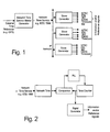
Fig. 1 illustrates a mode for synchronization of signals at multiple slave devices with a master generator that provides distributed precision network time service to slave reference signal generator devices. -
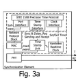
Fig. 2 illustrates a slave reference and/or information signal generating device -
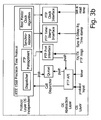
Fig. 3a shows hardware and software components of a synchronization element. -
Fig. 3b shows the interaction of the individual layers. -
Fig. 1 illustrates an apparatus for providing synchronization of signals at multiple slave devices. In this system, by way of example, a master network time generator provides distributed precision network time service to the master and all slave generator devices using a service such asIEEE 1588. The slave devices receive the network distributed time and use this information to deterministically generate video and audio information and/or reference signals. The independent slave generators will all produce signals which are time-aligned and synchronous with each other. The master generator preferably accepts an input from a time source, for example a highly stable reference such as an atomic clock or the Global Positioning System (GPS). Alternatively, the master generator can run on its own internal oscillator using last known time information. This generator may be specific to the implementation of a broadcast system, or may simply be the local 'house time' on the managed network infrastructure. - A mechanism suited for enabling the present concept is a network timekeeping service such as
IEEE 1588, IEC/ISO 61588 which provides a distributed time service using private traffic on an IP network, and may be optimized through the use of specialized switches. The reason for the specialized switches is that the precision of the protocol also depends on the latency jitter of the underlying network topology. Point to point connections provide the highest precision, with hubs imposing very little network jitter. Under very low or no network load, ISO Layer 2 switches have a very low processing time, typically 2 µs to 10µs plus packet reception time. Switches with about 0.4 µs latency jitter are also available. However, switches are working with queues and store and forward, so only one queued maximum length packet imposes a delay for the following packet in the 100 µs range, and under high load conditions, more than one packet will be in the queue. Another factor for the precision of the protocol is that latency is entirely symmetric for both directions: from the master to the slave and visa versa. - Reference signals are synchronized to align information signals associated with the reference signals. The information signals may be in different formats and/or may originate from different locations. As used herein an "information signal" or "information data" includes any signal which contains information in analog or digital form, for example currently standard video signals such as NTSC, PAL, SDI, MPEG-2, MPEG-4, and ATSC, and/or audio signals such as AES digital audio, MP3, MP4, etc. The present approach can be applied to information signals are to be aligned for superimposition, combination, integration, etc. by a broadcasting facility, editing facility or the like.
- The master generator reads time information from the absolute time input and synchronizes its
IEEE 1588 generator to it. By use of the associated external time base (for example from GPS), theIEEE 1588 master generator can provide extremely accurate time distribution to slave devices. - An arbitrary point in time is selected as an initial reference point (t=0), and all unrelated timing signals, clock edges and phase relationships are deemed to be in line at the initial reference point. The genlock time data will be used to calculate the position of each information signal at any later point in time at which the information signals are to be integrated or combined, and thus to calculate the phase offset of each signal relative to the other(s) so that compensating delays can be applied.
- The slave generators are each locked to the
IEEE 1588 network time. Compensation procedures within theIEEE 1588 protocol provide for delay compensation between the master and each slave, and thus ensure that each slave contains the same absolute time data at any instant in time. Using the time data, the slave is able to synthesize output signals and their time bases. For any signal previously defined in phase at some prior point in time, it is possible to calculate by software means the phase of that signal at any other point in time. The slave employs the necessary calculations to derive the required phase for its output signals from the ongoing timekeeping data. - The slave reference generator device illustrated in
Fig. 2 receives the network distributed time service, forexample IEEE 1588 which provides an ongoing time count. In addition, a reference time counter is implemented, clocked with a local time base. This time is compared with the received network time and an error value is produced. This error represents the time difference between the local reference time counter and the network distributed time. This error value is used to steer the frequency of the local time base such that if the local counter is at an earlier count value than the master counter at the time of comparison, the time base frequency is raised to increase the count rate of the local counter. Conversely, if the local counter has a greater count value than the master, the time base frequency is reduced. - From comparison to comparison, the frequency error of the local time base in the slave can be measured as error in timekeeping and this information can be used to steer to local time base to the correct frequency over time, using loop filtering techniques.
- As a result the slave genlock time counter will be synchronous to the genlock time counter in the master and signals derived from each slave will be synchronous to each other.
- At startup or reconnection to the network after some time of standalone operation, the slave genlock counter can differ significantly from the master count such that in inordinate time would be required to synchronize counts by offsetting the local time base due to limits in the time base offset allowed by certain reference signal standards. In this event, a loop management algorithm would initiate loading the local genlock counter with the master sampled value to achieve fast lock. Phase locking would commence thereafter.
- Now running in sync with the master counter, the slave counter can be used to synthesize genlock reference signals.
- The architecture of the master generator is based on the concept to separate the time-critical part which is implemented in hardware and the protocol itself and is decoupled from hard real-time conditions - the software part. Thus the protocol can be executed in a low priority process and/or on a processor with low performance requirements. The master generator has a highly precise real-time clock and a time stamp unit (TSU) to generate the time stamp. The software part implements the
actual IEEE 1588 protocol with an interface to the real-time clock and the hardware time stamp unit.Fig. 3a illustrates a co-operating of the hardware and software components of aIEEE 1588 synchronization element. - The intention of this architecture supports an almost Operating System (OS) independent modeling of the software component. Three layers with different abstraction level are provided. The Protocol Layer implements the operating system independent Precision Time Protocol (PTP). The OS Abstraction Layer forms the interface between PTP and the selected operating system. The functions made available by the operating system - tasks/processes, semaphores, timers, sockets, etc. - are merged over the OS Layer.
Fig. 3b illustrates the interaction of the individual layers. - The Protocol Layer, which is OS independent implements PTP for the synchronization of the devices in the IP network in a network. The actual processing for synchronizing the individual communication elements is located here. Within the Protocol Layer, the protocol dispatcher ensures the atomic execution of functions during an individual process. The Communication between the protocol and the OS Abstraction Layer is implemented by a queue and three interfaces.
- The middle layer, i.e. the OS abstraction Layer encases operating system dependent functions, which are to be adapted to the devices actually present in the network. The Timestamp Interface provides the Precision Time Protocol with the seized time stamps of the Sync and Delay-Request messages. However, depending upon the stage of the precision requirement, either a Hardware unit, i.e. the TSU, or the software generates the time stamps. One possibility to generate "software time stamps" is in the operating system dependent NIC drivers (RX- ISR, sends process) - as near as possible at the transportation medium. The local clock is read and modified via the Clock Interface.
- Implementations which do not have a hardware real-time clock can use the system clock of the operating system or optimized solutions as for example the nano-kernel under UNIX derivatives. Apart from setting the local clock, this interface contains the control algorithms which are responsible for the quality of time synchronization [accuracy, stability, transient behavior, etc.]. The Port Interface is used to dispatch and/or receive PTP messages. The
IEEE 1588 telegrams use excluding UDP/IP multicast packets and thus make it possible to send and receive them over the socket interface of the IP protocol stack. - A clock or timer is a device providing a measurement of the passage of time since a defined epoch. There may be two types of clocks: boundary clocks and ordinary clocks. A boundary clock is a clock with more than a single PTP port, with each PTP port providing access to a separate PTP communication path. Boundary clocks are used to eliminate fluctuations produced by routers and similar network elements. The point in the outbound and inbound protocol stacks where this timestamp is generated is called the clock timestamp point.
- The communication of PTP information between two PTP clocks with no intervening boundary clock is a direct communication. It is often desirable to synchronize a single clock to an external source of time, for example to a GPS system to establish a UTC time base. This synchronization is referred to as external synchronization. The reference time defining the origin of a time scale is termed the epoch. Within a collection of clocks one clock, the grandmaster clock, will serve as the primary source of time to which all others are ultimately synchronized. Within each region there will be a single clock, the master clock, serving as the primary source of time. The master clocks will in turn synchronize to other master clocks and ultimately to the grandmaster clock. Sync and Delay_Req messages contain a distinguished feature, the message timestamp point, serving as a reference point in these messages. When the message timestamp point passes the clock timestamp point, a timestamp is generated and used to compute the necessary corrections to the local clock. An ordinary clock is a clock with a single PTP port.
- PTP is an acronym for Precision Time Protocol. A PTP domain is a collection of one or more PTP subdomains. There are five designated message types: Sync, Delay_Req, Follow-up, Delay_Resp, and Management. PTP messages can be communicated via a multicast. In this style of communication any node may post a message and all nodes will receive this message.
- A PTP port is the logical access point for communications to the clock containing the port. Two clocks are synchronized to a specified uncertainty if they have the same epoch and measurements of any time interval by both clocks differ by no more than the specified uncertainty. The timestamps generated by two synchronized clocks for the same event will differ by no more than the specified uncertainty.
- While preferred apparatuses and methodologies having been thus described by way of example only, it will be apparent to those skilled in the art that certain modifications and adaptations may be made without departing from the scope of the appended claims.
Claims (10)
- A system for synchronizing unrelated information and/or reference signals originating from two or more broadcasting / multimedia equipment sources wherein said signals may be in different signal formats and/or subject to different delays at a receiving device, comprising• a data network containing one or more network time service(s),• a plurality of slave information and/or reference signal generators, wherein• at least one of said plurality of slave information and/or reference signal generators being adapted to accept the timekeeping data from said network time service as an input in order to generate an information and/or reference signal, the phase of which is calculated based on the time elapsed since an initial time point,• said one of said plurality of slave information and/or reference signal generators comprises a reference time counter to generate time data elapsed from said initial time point, and wherein• said reference time counter is connected to a source of network distributed time data.
- The system of any of claim 1, wherein• at least one of said reference time counters is clocked by a local time base, and/or• said reference time counter is part of a phase locked loop circuit locking the said reference time counter using the incoming network time and the locally running slave time data.
- A master reference time generator for transmitting signals for synchronizing unrelated information signals originating from two or more broadcasting / multimedia equipment sources wherein said signals may be in different signal formats and/or subject to different delays at a receiving device, comprising• a data network distributed timekeeping service, the master generator of which is assigned to be the master reference time generator.
- A slave information signal generator connected to a data network for receiving said network distributed timekeeping service, said time being transmitted by a master reference time generator according to claim 3, wherein• said slave information signal generator is adapted to regenerate the counting of the master reference generator time counter, preferably by means of a phase locked loop; and• said slave information signal generator is adapted to calculate a phase of one or more information and/or reference signal(s) based on the time elapsed since an initial time point.
- The system of any of claims 1 - 4, wherein said time network distributed timekeeping is provided by an instance of IEEE1588 / ISO/IEC61588 operating an IP network.
- A method for synchronizing unrelated information and/or reference signals originating from two or more broadcasting / multimedia equipment sources wherein said signals may be in different signal formats and/or subject to different delays at a receiving device, comprising the steps of• providing a data network containing one or more network time service(s),• providing a plurality of slave information and/or reference signal generators, wherein• at least one of said plurality of slave information and/or reference signal generators being adapted to accept the timekeeping data from said network time service as an input in order to generate an information and/or reference signal,• calculating the phase of one or more information and/or reference signals based on the time elapsed since an initial time point,• generating information and/or reference signals from the calculated phase information.
- The method of claim 6, further comprising the steps of• connecting one or more master reference time generators to said data network, wherein said master reference time generators provide distributed time services to devices on the network, and;• connecting one or more of a plurality of slave devices to the data network, wherein each of said slave devices being capable of accepting the distributed time data as an input.
- The method of claim 6, further comprising the step of• accepting, at said master reference time generator, an absolute time reference as an input which is either an externally provided time, or an optional time base to load and clock the time of the master reference time generator, or the time and time base are local to said master reference time generator, and• distributing the time network time service.
- The method as defined in any of claims 6 - 8, comprising the step of• clocking, in at least one of said slave reference signal generators, a reference time counter by a local time base, and/or• implementing a phase locked loop to lock the slave reference time counter using the incoming network distributed time and the locally running slave reference time data, and/or• loading, at device startup said counter at said slave reference signal generator with the most recently received reference time count.
- The method as defined in any of the previous claims, comprising the step of• distributing a time reference signal over an IP network to synchronize, in the sub-microsecond range, broadcasting / multimedia devices using the same network that also transports the TV / radio / multimedia information data.
Priority Applications (6)
| Application Number | Priority Date | Filing Date | Title |
|---|---|---|---|
| EP08019378A EP2187619A1 (en) | 2008-11-05 | 2008-11-05 | Improved method, system and apparatus for synchronizing signals |
| CA2684227A CA2684227C (en) | 2008-11-05 | 2009-10-30 | Improved method, system and apparatus for synchronizing signals |
| KR1020117012155A KR101261123B1 (en) | 2008-11-05 | 2009-11-05 | Improved method, system and apparatus for synchronizing signals |
| US12/612,786 US8095615B2 (en) | 2008-11-05 | 2009-11-05 | System for synchronizing signals including a slave signal generator generating elapsed time data with respect to an initial time point and related methods |
| JP2011534911A JP5497051B2 (en) | 2008-11-05 | 2009-11-05 | Improved method, system and apparatus for signal synchronization |
| PCT/US2009/063326 WO2010054030A1 (en) | 2008-11-05 | 2009-11-05 | Improved method, system and apparatus for synchronizing signals |
Applications Claiming Priority (1)
| Application Number | Priority Date | Filing Date | Title |
|---|---|---|---|
| EP08019378A EP2187619A1 (en) | 2008-11-05 | 2008-11-05 | Improved method, system and apparatus for synchronizing signals |
Publications (1)
| Publication Number | Publication Date |
|---|---|
| EP2187619A1 true EP2187619A1 (en) | 2010-05-19 |
Family
ID=40535526
Family Applications (1)
| Application Number | Title | Priority Date | Filing Date |
|---|---|---|---|
| EP08019378A Ceased EP2187619A1 (en) | 2008-11-05 | 2008-11-05 | Improved method, system and apparatus for synchronizing signals |
Country Status (6)
| Country | Link |
|---|---|
| US (1) | US8095615B2 (en) |
| EP (1) | EP2187619A1 (en) |
| JP (1) | JP5497051B2 (en) |
| KR (1) | KR101261123B1 (en) |
| CA (1) | CA2684227C (en) |
| WO (1) | WO2010054030A1 (en) |
Cited By (4)
| Publication number | Priority date | Publication date | Assignee | Title |
|---|---|---|---|---|
| FR2960666A1 (en) * | 2010-05-27 | 2011-12-02 | Airbus Operations Sas | METHOD AND DEVICE FOR SYNCHRONIZATION AND DATATION FOR EQUIPMENT OF AN AFDX COMMUNICATION NETWORK |
| CN103281171A (en) * | 2013-05-10 | 2013-09-04 | 国家电网公司 | Multi-clock synchronization method of distributed type sampling value network |
| FR3051929A1 (en) * | 2016-05-31 | 2017-12-01 | Gorgy Timing | TEMPORAL ARBITRATION CIRCUIT |
| EP4033746A1 (en) * | 2021-01-22 | 2022-07-27 | Canon Kabushiki Kaisha | Method for generating control signals for an image capture device |
Families Citing this family (38)
| Publication number | Priority date | Publication date | Assignee | Title |
|---|---|---|---|---|
| US8170012B2 (en) * | 2007-06-12 | 2012-05-01 | Thomson Licensing | Phase control of a synchronization signal in a packet switching network |
| FR2920928A1 (en) * | 2007-09-07 | 2009-03-13 | Thomson Licensing Sas | REDUCING THE DURATION OF HANGING OF A PHASE LOCKED LOOP THAT REASSIGNS A SYNCHRONIZATION SIGNAL TRANSMITTED OVER AN IP NETWORK. |
| FR2920943A1 (en) * | 2007-09-07 | 2009-03-13 | Thomson Licensing Sas | METHOD AND DEVICE FOR AUTOMATIC COMPSENSATION OF A PHASE DIFFERENCE ON A SYNCHRONIZATION SIGNAL RECEIVED BY REMOTE EQUIPMENT |
| EP2150062B1 (en) * | 2008-07-28 | 2022-10-26 | Imagine Communications Corp. | Improved method, system and apparatus for synchronizing signals |
| US8718482B1 (en) * | 2009-11-10 | 2014-05-06 | Calix, Inc. | Transparent clock for precision timing distribution |
| EP2330824A1 (en) * | 2009-11-27 | 2011-06-08 | Thomson Licensing | Local statistical multiplexing of video streams over internet protocol |
| US8327029B1 (en) * | 2010-03-12 | 2012-12-04 | The Mathworks, Inc. | Unified software construct representing multiple synchronized hardware systems |
| US8775849B2 (en) | 2010-05-10 | 2014-07-08 | Ikanos Communications, Inc. | Systems and methods for transporting time-of-day information in a communication system |
| CN102244925B (en) * | 2010-05-14 | 2014-05-07 | 华为技术有限公司 | Clock synchronization method, client equipment and clock synchronization system |
| US8670439B2 (en) * | 2010-07-02 | 2014-03-11 | Futurewei Technologies, Inc. | Method for accurate distribution of time to a receiver node in an access network |
| US8625640B2 (en) * | 2010-08-02 | 2014-01-07 | Futurewei Technologies, Inc. | Transparent clocks in access networks |
| US8346860B2 (en) | 2010-10-08 | 2013-01-01 | Lumi Technologies Limited | Multi-phased and partitioned content preparation and delivery |
| CN102006159B (en) * | 2010-12-08 | 2013-06-12 | 江苏方天电力技术有限公司 | Multi-slave clock sampling value multi-interface synchronizing system based on IEEE1588 |
| CN102098154A (en) * | 2011-01-29 | 2011-06-15 | 华为技术有限公司 | Method for transmitting precision clock synchronization protocol messages, apparatus and system thereof |
| JP5811794B2 (en) * | 2011-11-16 | 2015-11-11 | 富士通株式会社 | Communication device |
| US20170039867A1 (en) | 2013-03-15 | 2017-02-09 | Study Social, Inc. | Mobile video presentation, digital compositing, and streaming techniques implemented via a computer network |
| US9541947B2 (en) | 2013-08-07 | 2017-01-10 | General Electric Company | Time protocol based timing system for time-of-flight instruments |
| CN103929294B (en) * | 2014-05-05 | 2017-09-12 | 浙江大学 | A kind of clock system and synchronous method |
| KR101596756B1 (en) * | 2014-11-03 | 2016-03-07 | 현대자동차주식회사 | Method and apparatus for providing in-vehicle network time synchronization using redundant GrandMaster |
| CA2912461C (en) | 2014-11-17 | 2020-11-24 | Skotel Corporation | Method and apparatus for deterministic date and time alignment of media signals and generation of time-related labels |
| US10462818B2 (en) * | 2014-12-16 | 2019-10-29 | Robert Bosch Gmbh | Method of transmitting data between network devices over a non-deterministic network |
| RU2660458C1 (en) * | 2014-12-16 | 2018-07-06 | Роберт Бош Гмбх | Method for synchronization of clock generators of network devices |
| KR101682978B1 (en) * | 2016-07-26 | 2016-12-07 | 쿨사인 주식회사 | Precision Time Protocol . |
| EP3382918B1 (en) * | 2017-03-30 | 2022-09-28 | ADVA Optical Networking SE | System and method of clock management in a packet data network |
| WO2019023515A1 (en) | 2017-07-26 | 2019-01-31 | Aviat Networks, Inc. | Distributed radio transparent clock over a wireless network |
| SG11202000761VA (en) * | 2017-07-26 | 2020-02-27 | Aviat Networks Inc | Airframe timestamping technique for point-to-point radio links |
| TW201931863A (en) * | 2018-01-12 | 2019-08-01 | 圓剛科技股份有限公司 | Multimedia signal synchronization apparatus and synchronization method thereof |
| WO2020075235A1 (en) * | 2018-10-10 | 2020-04-16 | 株式会社メディアリンクス エルエスアイラボ | Clock generation device and clock generation method |
| CN110362628A (en) * | 2019-06-20 | 2019-10-22 | 视联动力信息技术股份有限公司 | A kind of synchronous method and device cascading file |
| US11876609B2 (en) * | 2019-07-18 | 2024-01-16 | Nippon Telegraph And Telephone Corporation | Time sync device, time sync method, and program |
| US11683092B2 (en) | 2020-02-24 | 2023-06-20 | Ciena Corporation | Loss-based wavelength meter |
| US11381787B2 (en) * | 2020-03-09 | 2022-07-05 | Canon Kabushiki Kaisha | Image capturing apparatus, method for controlling same, and non-transitory computer-readable storage medium |
| US11768391B2 (en) | 2021-02-05 | 2023-09-26 | Ciena Corporation | Carrier depletion-based silicon photonic modulator using capacitive coupling |
| US12278694B2 (en) | 2022-02-25 | 2025-04-15 | Electronics And Telecommunications Research Institute | Method and apparatus for synchronizing signals of signal measuring devices |
| US12149291B2 (en) | 2022-03-17 | 2024-11-19 | Ciena Corporation | Coherent receiver having low VOA-induced phase changes |
| US12546706B2 (en) | 2022-03-31 | 2026-02-10 | Ciena Corporation | Optical referencing from optical references with variable perturbative drift rates |
| EP4584761A4 (en) | 2022-09-09 | 2026-05-20 | Tesla Inc | METHOD FOR MODELING ARTIFICIAL INTELLIGENCE FOR VISUALLY BASED OCCUPANCY DETERMINATION |
| WO2024237939A2 (en) * | 2022-09-30 | 2024-11-21 | Tesla, Inc. | Artificial intelligence modeling techniques for vision-based surface determination |
Citations (4)
| Publication number | Priority date | Publication date | Assignee | Title |
|---|---|---|---|---|
| EP1513044A1 (en) | 2003-09-04 | 2005-03-09 | Broadcom Corporation | Clock drift compensation using network time protocol |
| US20050207387A1 (en) * | 2004-02-09 | 2005-09-22 | Semtech Corporation | Method and apparatus for aligning time references when separated by an unreliable data packet network |
| WO2006110960A1 (en) * | 2005-04-22 | 2006-10-26 | National Ict Australia Limited | Method for transporting digital media |
| US20080122986A1 (en) | 2006-09-19 | 2008-05-29 | Florian Diederichsen | Method and system for live video production over a packeted network |
Family Cites Families (11)
| Publication number | Priority date | Publication date | Assignee | Title |
|---|---|---|---|---|
| JP2000332802A (en) * | 1999-05-24 | 2000-11-30 | Sony Corp | Communication method, communication system, communication terminal, and relay device |
| US6823031B1 (en) * | 2000-01-20 | 2004-11-23 | Wavtrace, Inc. | Automated frequency compensation for remote synchronization |
| DE102004055105A1 (en) * | 2004-11-15 | 2006-05-24 | Bosch Rexroth Aktiengesellschaft | Method for time synchronization in a cyclic communication system |
| US7639311B2 (en) | 2006-01-24 | 2009-12-29 | Montage Technology Group Limited | CMOS integrated super-heterodyne television receiver with multiple signal paths |
| US7589595B2 (en) * | 2006-08-18 | 2009-09-15 | Agilent Technologies, Inc. | Distributing frequency references |
| KR100895175B1 (en) * | 2007-04-04 | 2009-05-04 | 삼성전자주식회사 | Method and apparatus for synchronizing time using GPS information in communication system |
| KR100876776B1 (en) * | 2007-04-17 | 2009-01-09 | 삼성전자주식회사 | Method and apparatus for synchronizing time using GPS information in communication system |
| US20090113183A1 (en) * | 2007-10-31 | 2009-04-30 | Agilent Technologies, Inc. | Method of controlling a device and a device controlled thereby |
| US8018950B2 (en) * | 2008-03-17 | 2011-09-13 | Wi-Lan, Inc. | Systems and methods for distributing GPS clock to communications devices |
| EP2150062B1 (en) * | 2008-07-28 | 2022-10-26 | Imagine Communications Corp. | Improved method, system and apparatus for synchronizing signals |
| US8416812B2 (en) * | 2008-09-22 | 2013-04-09 | Codrut Radu Radulescu | Network timing synchronization systems |
-
2008
- 2008-11-05 EP EP08019378A patent/EP2187619A1/en not_active Ceased
-
2009
- 2009-10-30 CA CA2684227A patent/CA2684227C/en active Active
- 2009-11-05 US US12/612,786 patent/US8095615B2/en active Active
- 2009-11-05 WO PCT/US2009/063326 patent/WO2010054030A1/en not_active Ceased
- 2009-11-05 JP JP2011534911A patent/JP5497051B2/en active Active
- 2009-11-05 KR KR1020117012155A patent/KR101261123B1/en active Active
Patent Citations (4)
| Publication number | Priority date | Publication date | Assignee | Title |
|---|---|---|---|---|
| EP1513044A1 (en) | 2003-09-04 | 2005-03-09 | Broadcom Corporation | Clock drift compensation using network time protocol |
| US20050207387A1 (en) * | 2004-02-09 | 2005-09-22 | Semtech Corporation | Method and apparatus for aligning time references when separated by an unreliable data packet network |
| WO2006110960A1 (en) * | 2005-04-22 | 2006-10-26 | National Ict Australia Limited | Method for transporting digital media |
| US20080122986A1 (en) | 2006-09-19 | 2008-05-29 | Florian Diederichsen | Method and system for live video production over a packeted network |
Non-Patent Citations (2)
| Title |
|---|
| "IEEE1588 and Switches", INTERNET CITATION, pages 1 - http://ww, XP002572809 * |
| ANONYMOUS: "Phase-locked loop", WIKIPEDIA, 27 October 2008 (2008-10-27), XP002524983, Retrieved from the Internet <URL:http://en.wikipedia.org/w/index.php?title=Phase-locked_loop&oldid=247981307> [retrieved on 20090422] * |
Cited By (9)
| Publication number | Priority date | Publication date | Assignee | Title |
|---|---|---|---|---|
| FR2960666A1 (en) * | 2010-05-27 | 2011-12-02 | Airbus Operations Sas | METHOD AND DEVICE FOR SYNCHRONIZATION AND DATATION FOR EQUIPMENT OF AN AFDX COMMUNICATION NETWORK |
| US8649303B2 (en) | 2010-05-27 | 2014-02-11 | Airbus Operations S.A.S. | Method and device for synchronizing and time-stamping for equipment items of a communication network of AFDX type |
| CN103281171A (en) * | 2013-05-10 | 2013-09-04 | 国家电网公司 | Multi-clock synchronization method of distributed type sampling value network |
| CN103281171B (en) * | 2013-05-10 | 2016-05-04 | 国家电网公司 | The multi-clock synchronization method of distributed sample value networking |
| FR3051929A1 (en) * | 2016-05-31 | 2017-12-01 | Gorgy Timing | TEMPORAL ARBITRATION CIRCUIT |
| WO2017207932A1 (en) * | 2016-05-31 | 2017-12-07 | Gorgy Timing | Time arbitration circuit |
| US10901455B2 (en) | 2016-05-31 | 2021-01-26 | Scptime | Time arbitration circuit |
| EP4033746A1 (en) * | 2021-01-22 | 2022-07-27 | Canon Kabushiki Kaisha | Method for generating control signals for an image capture device |
| US11985295B2 (en) | 2021-01-22 | 2024-05-14 | Canon Kabushiki Kaisha | Method for generating control signals for an image capture device |
Also Published As
| Publication number | Publication date |
|---|---|
| KR20110082588A (en) | 2011-07-19 |
| CA2684227A1 (en) | 2010-05-05 |
| JP5497051B2 (en) | 2014-05-21 |
| US8095615B2 (en) | 2012-01-10 |
| JP2012511267A (en) | 2012-05-17 |
| WO2010054030A1 (en) | 2010-05-14 |
| KR101261123B1 (en) | 2013-05-06 |
| US20100115047A1 (en) | 2010-05-06 |
| CA2684227C (en) | 2017-06-06 |
Similar Documents
| Publication | Publication Date | Title |
|---|---|---|
| CA2684227C (en) | Improved method, system and apparatus for synchronizing signals | |
| EP2150062B1 (en) | Improved method, system and apparatus for synchronizing signals | |
| US8964790B2 (en) | Communication apparatus | |
| US8073060B2 (en) | Video synchronization | |
| EP1222759B1 (en) | Method and apparatus for upstream burst transmission synchronization in cable modems | |
| EP1256197B1 (en) | Reference time distribution over a network | |
| US7630407B2 (en) | Frequency synchronisation of clocks | |
| US9277256B2 (en) | Node and system for a synchronous network | |
| US20120099521A1 (en) | Center district dual mode network synchronization acquisition method and apparatus for satellite communication system | |
| CN102577194A (en) | Measurement and adjustment based on real-time values of dwell time in network equipment without access to real-time | |
| US10595075B2 (en) | Automatic timing of production devices in an internet protocol environment | |
| US11012171B2 (en) | Deterministic re-multiplexing for DVB SFN networks | |
| US8170012B2 (en) | Phase control of a synchronization signal in a packet switching network | |
| WO2026028820A1 (en) | Auxiliary data inserter and program related to smpte st2110 | |
| WO2020075235A1 (en) | Clock generation device and clock generation method |
Legal Events
| Date | Code | Title | Description |
|---|---|---|---|
| PUAI | Public reference made under article 153(3) epc to a published international application that has entered the european phase |
Free format text: ORIGINAL CODE: 0009012 |
|
| AK | Designated contracting states |
Kind code of ref document: A1 Designated state(s): AT BE BG CH CY CZ DE DK EE ES FI FR GB GR HR HU IE IS IT LI LT LU LV MC MT NL NO PL PT RO SE SI SK TR |
|
| AX | Request for extension of the european patent |
Extension state: AL BA MK RS |
|
| 17P | Request for examination filed |
Effective date: 20100623 |
|
| 17Q | First examination report despatched |
Effective date: 20100812 |
|
| AKX | Designation fees paid |
Designated state(s): AT BE BG CH CY CZ DE DK EE ES FI FR GB GR HR HU IE IS IT LI LT LU LV MC MT NL NO PL PT RO SE SI SK TR |
|
| STAA | Information on the status of an ep patent application or granted ep patent |
Free format text: STATUS: THE APPLICATION HAS BEEN REFUSED |
|
| 18R | Application refused |
Effective date: 20120214 |