EP2187382A2 - Video apparatus and method of controlling the video apparatus - Google Patents
Video apparatus and method of controlling the video apparatus Download PDFInfo
- Publication number
- EP2187382A2 EP2187382A2 EP09173279A EP09173279A EP2187382A2 EP 2187382 A2 EP2187382 A2 EP 2187382A2 EP 09173279 A EP09173279 A EP 09173279A EP 09173279 A EP09173279 A EP 09173279A EP 2187382 A2 EP2187382 A2 EP 2187382A2
- Authority
- EP
- European Patent Office
- Prior art keywords
- information
- function
- video apparatus
- video
- player
- Prior art date
- Legal status (The legal status is an assumption and is not a legal conclusion. Google has not performed a legal analysis and makes no representation as to the accuracy of the status listed.)
- Withdrawn
Links
Images


Classifications
-
- G—PHYSICS
- G09—EDUCATION; CRYPTOGRAPHY; DISPLAY; ADVERTISING; SEALS
- G09G—ARRANGEMENTS OR CIRCUITS FOR CONTROL OF INDICATING DEVICES USING STATIC MEANS TO PRESENT VARIABLE INFORMATION
- G09G5/00—Control arrangements or circuits for visual indicators common to cathode-ray tube indicators and other visual indicators
- G09G5/003—Details of a display terminal, the details relating to the control arrangement of the display terminal and to the interfaces thereto
- G09G5/006—Details of the interface to the display terminal
-
- G—PHYSICS
- G09—EDUCATION; CRYPTOGRAPHY; DISPLAY; ADVERTISING; SEALS
- G09G—ARRANGEMENTS OR CIRCUITS FOR CONTROL OF INDICATING DEVICES USING STATIC MEANS TO PRESENT VARIABLE INFORMATION
- G09G2370/00—Aspects of data communication
- G09G2370/04—Exchange of auxiliary data, i.e. other than image data, between monitor and graphics controller
- G09G2370/045—Exchange of auxiliary data, i.e. other than image data, between monitor and graphics controller using multiple communication channels, e.g. parallel and serial
- G09G2370/047—Exchange of auxiliary data, i.e. other than image data, between monitor and graphics controller using multiple communication channels, e.g. parallel and serial using display data channel standard [DDC] communication
-
- G—PHYSICS
- G09—EDUCATION; CRYPTOGRAPHY; DISPLAY; ADVERTISING; SEALS
- G09G—ARRANGEMENTS OR CIRCUITS FOR CONTROL OF INDICATING DEVICES USING STATIC MEANS TO PRESENT VARIABLE INFORMATION
- G09G2370/00—Aspects of data communication
- G09G2370/10—Use of a protocol of communication by packets in interfaces along the display data pipeline
-
- G—PHYSICS
- G09—EDUCATION; CRYPTOGRAPHY; DISPLAY; ADVERTISING; SEALS
- G09G—ARRANGEMENTS OR CIRCUITS FOR CONTROL OF INDICATING DEVICES USING STATIC MEANS TO PRESENT VARIABLE INFORMATION
- G09G2370/00—Aspects of data communication
- G09G2370/12—Use of DVI or HDMI protocol in interfaces along the display data pipeline
Definitions
- the present general inventive concept relates to a video apparatus and a method to control the video apparatus, and more particularly, to a video apparatus to control functions using an A/V interface capable of two-way communication and a method for controlling the video apparatus thereof.
- AV audio/visual
- a user can watch an image with higher image quality and higher quality than ever before.
- a user can use a home theater system to enjoy a theater-like atmosphere at home.
- a user desires to watch high-quality images, and therefore a method to automatically select appropriate functions for televisions and external AV devices is needed.
- the present general inventive concept provides a video apparatus to receive information regarding an external device and external device function from the external device via an interface, and transmit information regarding the video apparatus and video apparatus function to the external device and a method to control the video apparatus thereof.
- the present general inventive concept also provides a video apparatus to transmit information regarding video apparatus and video apparatus functions to an external device via an image signal channel and to receive information regarding the external devices and external device functions from the external device via a data channel of interface and a method to control the video apparatus thereof.
- a video apparatus connectable to an external apparatus which includes an interface connectable to the external apparatus and a control unit to transmit apparatus and function information of the video apparatus to the external apparatus and to receive device and function information of the external apparatus from the external apparatus, wherein the function information of the video apparatus includes information regarding whether the video apparatus supports a certain function, wherein the function information of the external apparatus includes information regarding whether the external apparatus supports a certain function, and wherein the control unit executes the certain function if the external apparatus and the video apparatus supports the certain function.
- the certain function may include functions regarding an image quality mode of an image.
- the video apparatus may receive data of which an image quality is not adjusted from the external apparatus and may adjust an image quality of the image.
- At least one of resolution, sharpness, brightness, noise reduction, hue, and saturation may be adjusted.
- the interface may be high definition multimedia interface (HDMI) interface.
- HDMI high definition multimedia interface
- the external apparatus may be received in a source product description (SPD) InfoFrame format, and the function information of the external apparatus may be included in at least one data byte included in the SPD InfoFrame.
- SPD source product description
- the control unit may transmit the information of the video apparatus to the external apparatus in an enhanced display identification data (EDID) format, and may record and transmit the function information of the video apparatus in at least one byte included in the EDID.
- EDID enhanced display identification data
- a method to control a video system in which a video apparatus is connectable to an external apparatus via an interface which includes transmitting apparatus and function information of the video apparatus to the external apparatus, receiving apparatus and function information of the external apparatus, and executing a certain function if the external apparatus and the video apparatus support the certain function, wherein the function information of the video apparatus includes information regarding whether the video apparatus supports the certain function and wherein the function information of the external apparatus includes information regarding whether the external apparatus supports the certain function.
- the certain function may include a function related to an image quality mode of an image.
- the video apparatus may receive data of which an image quality mode is not adjusted from the external apparatus and may adjust the image quality mode of the image.
- the image quality mode may adjust at least one of resolution, sharpness, brightness, noise reduction, hue, and saturation.
- the receiving may receive the information regarding device and function of the external apparatus via an image signal channel of the interface, and the transmitting may transmit information regarding device and function of the video apparatus to the external apparatus via a data channel of the interface.
- the interface may be high definition multimedia interface (HDMI).
- HDMI high definition multimedia interface
- the image signal channel may be a transition minimized differential signaling (TMDS) of the HDMI interface and the data channel may be a display data channel (DDC) of the HDMI interface.
- TMDS transition minimized differential signaling
- DDC display data channel
- an external apparatus connectable to a video apparatus which includes an interface connectable to the video apparatus and a control unit to transmit information regarding apparatus and function of the external apparatus to the video apparatus and to receive apparatus and function information of the video apparatus from the video apparatus, wherein the function information of the external apparatus includes information regarding whether the external apparatus supports a certain function and the function information of the video apparatus includes information regarding whether the video apparatus supports the certain function, and wherein the control unit executes the certain function if the external apparatus and the video apparatus support the certain function.
- the certain function may include a function related to an image quality mode of an image.
- the external apparatus data of which an image quality is not adjusted may be transmitted to the video apparatus so that the video apparatus may adjust the image quality mode of the image.
- the image quality mode may adjust at least one of resolution, sharpness, brightness, noise reduction, hue, and saturation.
- an external apparatus is connectable to a video apparatus via an interface which includes transmitting apparatus and function information of the external apparatus to the video apparatus, receiving apparatus and function information of the video apparatus from the video apparatus and executing a certain function if the function information of the video apparatus indicates that the video apparatus supports the certain function and the external apparatus also supports the certain function, wherein the function information of the external apparatus includes information regarding whether the external apparatus supports the certain function, and wherein the function information of the video apparatus includes information regarding whether the video apparatus supports the certain function.
- a video apparatus which includes an interface to communicate with an external apparatus, and a control unit to transmit a first information of the video apparatus to the external apparatus and to receive a second information of the external apparatus, wherein the control unit executes a certain function if the first information corresponds to the second information.
- the first information may include a first device information and a first function information of the video apparatus.
- the second information may include a second device information and a second function information of the external apparatus.
- the control unit may execute the certain function if the first and second function information support the certain function.
- the interface may receive and transmit information signals and image data signals through HDMI interface channels, the information signals may include the first information and the second information, and the information signals may be transmitted between the image data signals.
- a computer readable storage medium containing a method of controlling a video apparatus connectable to an external device, the method including receiving first device information and first function information of the external device, comparing the first device information and the first function information with a second device information and a second function information of the video apparatus, and transmitting a signal to the video apparatus to execute a certain function when the first function information and the second function information support the certain function.
- FIG. 1 is a schematic view of a video system according to an exemplary embodiment of the present general inventive concept.
- the video system includes a television apparatus (TV) 200 and a data storing and reproducing apparatus, such as a Blue-ray Disk (BD) player 300 connectable to each other through an interface capable of two-way communication.
- TV television apparatus
- BD Blue-ray Disk
- FIG. 1 illustrates the BD player 300 as the data storing and reproducing apparatus, the present general inventive concept is not limited thereto.
- the interface connecting the TV 200 with the BD player 300 may be a high definition multimedia interface (HDMI), since HDMI includes a channel capable of two-way communication.
- HDMI high definition multimedia interface
- any A/V interface capable of two-way communication may be applied.
- the BD player 300 reads out image and sound signals recorded on the BD and transmits the image and sound signals to the TV 200.
- a device which provides image and sound signals is referred to as a source device based on HDMI standards.
- the BD player 300 regularly transmits information regarding the device (such as, the name of manufacturer, model, and etc.) and certain functions (such as, whether an image quality mode is supported) to the TV 200 through an image receiving channel to inform the TV 200 of information regarding the BD player 300 and certain functions that the BD player 300 supports.
- information regarding the device such as, the name of manufacturer, model, and etc.
- certain functions such as, whether an image quality mode is supported
- the certain functions include at least one of a function regarding image quality mode of an image or a type of the image source.
- the examples of functions regarding image quality mode include screen ratio adjustment, brightness adjustment, and scaling.
- the examples of functions regarding image source include movie mode, news mode, drama mode, and etc.
- the present general inventive concept is not limited thereto.
- the TV 200 receives an image signal and a sound signal from the BD player 300 and displays these signals on a display screen.
- the apparatus which receives image signals and sound signals and displays them on the display screen is called a sink device, based on HDMI standards.
- the TV 200 regularly transmits information regarding the device (i.e., device information) such as, the name of manufacturer, model, and etc. and certain functions (such as, whether image quality mode is supported) to the BD player 300 through a data channel to inform the BD player 300 of information regarding the TV 200 and which functions the TV 200 supports.
- device information i.e., device information
- certain functions such as, whether image quality mode is supported
- the present general inventive concept is not limited thereto.
- the TV 200 and the BD player 300 can confirm with each other whether to support a function to provide optimum image quality.
- the TV 200 and the BD player 300 can identify whether certain functions are supported based on function information received from each other, and therefore can execute optimum functions for each device.
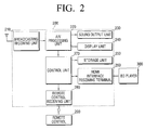
- the structure of the TV 200 will be explained in detail with reference to FIG. 2 .
- the TV 200 includes a broadcasting receiving unit 210, an A/V processing unit 220, a sound output unit 230, a display unit 240, a storage unit 250, a HDMI interface receiving terminal 260, a control unit 270, and a remote control receiving unit 280.
- the broadcasting receiving unit 210 receives wired or wireless broadcasting from a broadcasting station or a satellite and demodulates the broadcasting.
- the present general inventive concept is not limited thereto.
- the A/V processing unit 220 performs a signal processing such as a video decoding, video scaling, or audio decoding on the image signal and sound signal input from the broadcasting receiving unit 210 and the control unit 270.
- the A/V processing unit 220 output the image signal to the display unit 240, and the sound signal to the sound output unit 230.
- the sound output unit 230 outputs the sound output from the A/V processing unit 220 through a speaker (not illustrated).
- the display unit 240 displays the image output from the A/V processing unit 220.
- the display unit 240 displays an image showing a process of booting the TV 200 on a screen.
- the storage unit 250 stores the recorded image.
- the storage unit 250 may include a hard-disk, non-volatile memory, and flash memory.
- the present general inventive concept is not limited thereto.
- the HDMI interface receiving terminal 260 receives an image signal and a sound signal from the BD player 300 connected via a HDMI cable.
- the structure of the HDMI interface receiving terminal 260 will be explained in detail with reference to FIG. 5 .
- the remote control receiving unit 280 receives a command by a user and transmits the command to the control unit 270.
- the control unit 270 identifies the user's command based on the manipulation received from the remote control 290, and controls comprehensive operation of the TV 200 according to the identified command.
- the control unit 270 receives device information and function information of the BD player 300 from the BD player 300 via the HDMI interface receiving terminal 260.
- the control unit 270 transmits the device information and function information of the TV 200 to the BD player 300 via the HDMI interface receiving terminal 260.
- the control unit 260 transmits the device information and function information of the TV 200 through the data channel of the HDMI interface receiving terminal 260. More specifically, the control unit 260 transmits the device information and function information of the TV 200 through a HDMI interface display data channel (DDC) of the HDMI interface receiving channel 260.
- DDC HDMI interface display data channel
- the control unit 270 transmits device information of the TV 200 to the BD player 300 in an enhanced display identification data (EDID) format.
- the control unit 270 records function information of the TV 200 in at least one byte included in the EDID. Accordingly, the control unit 270 transmits device information and function information of the TV 200 in the EDID format to the BD player 300.
- EDID enhanced display identification data
- the device information of the TV 200 is system information of the TV 200 or information regarding specification, and includes information such as the name of manufacturer and the name of model of the TV 200.
- the device information of the TV 200 may be "SAMSUNG”, which is a manufacturer name, and "L3", which is a model name.
- the present general inventive concept is not limited thereto.
- the function information of the TV 200 represents information regarding whether certain functions are supported by the TV 200.
- the certain functions are functions regarding image quality of an image or the type of image source.
- the examples of functions regarding image quality mode include screen ratio adjustment, brightness adjustment, and scaling.
- examples of functions regarding image source include movie mode, news mode, drama mode, and etc.
- the present general inventive concept is not limited thereto.
- the function information of the TV 200 may be recorded in bytes, of which the address is 0Bh in the EDID. If the byte of address 0Bh is 1, that means the TV 200 supports certain functions, and if the byte of address 0Bh is 0, that means the TV 200 does not support certain functions.
- the EDID format including function information will be explained with reference to FIGS. 8 and 9 .
- the control unit 270 receives device information and function information of the BD player 300 from the BD player 300 through an image signal channel of the HDMI interface receiving terminal 260.
- the image signal channel may be a transition minimized differential signaling (TMDS) signal of the HDMI interface.
- TMDS transition minimized differential signaling
- the control unit 270 receives device information of the BD player 300 in a source product description (SPD) InfoFrame format.
- the function information of the BD player 300 is recorded in at least one byte included in the SPD InfoFrame. Accordingly, the control unit 270 determines whether certain functions are supported by the BD player 300.
- the device information of the BD player 300 is system information of the BD player 300 or information regarding specification, and includes information such as the name of manufacturer and name of model of the BD player 300.
- the device information of the BD player 300 may be "SAMSUNG”, which is a manufacturer name, and "BD-1600", which is a model name.
- the function information of the BD player 300 represents information regarding whether certain functions are supported by the BD player 300.
- the certain functions are functions regarding image quality of an image or the type of image source.
- the examples of functions regarding image quality mode include screen ratio adjustment, brightness adjustment, and scaling.
- examples of functions regarding image source include movie mode, news mode, drama mode, and etc.
- the present general inventive concept is not limited thereto.
- function information of the BD player 300 may be recorded in the 24 th byte of the SPD InfoFrame. If the 24 th byte is 1, that means the BD player 300 supports certain functions, but if the 24 th byte is 0, that means the BD player 300 does not support certain functions.
- the SPID InfoFrame format including function information will be explained with reference to FIGS. 6 and 7 .
- the control unit 270 executes the certain functions. For instance, if both the TV 200 and the BD player 300 support a wide screen mode, the TV 200 checks function information of the BD player 300 received when the BD player 300 is connected to the TV 200 and executes the wide screen mode.
- the TV 200 By receiving function information from the BD player 300, the TV 200 is able to execute optimum functions in combination with the BD player 300. By receiving function information as well as device information of the BD player 300, the TV 200 is able to execute functions appropriate to the BD player 300. As the TV 200 transmits the device information and function information of the TV 200, the BD player 300 is also able to execute functions appropriate to the TV 200.
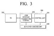
- FIG. 3 is a block diagram illustrating a structure of the BD player 300 according to an exemplary embodiment of the present general inventive concept.
- the BD player 300 includes a HDMI interface transmitting terminal 310, a control unit 320, and a BD player function unit 330.
- the BD player function unit 330 executes usual functions as a BD player. For instance, the BD player function unit 330 reads out an image and sound signal of an inserted BD and transmits the signals to the TV 200, which is connected to the BD player.
- the HDMI interface transmitting terminal 310 is connected to the TV 200 through a HDMI cable.
- the HDMI interface transmitting terminal 310 transmits the image and sound signals read out from the BD to the TV 200.
- the HDMI interface transmitting terminal 310 will be explained in detail with reference to FIG. 5 .
- the control unit 320 transmits device information and function information of the BD player 300 to the TV 200 through an image signal channel of the HDMI interface transmitting terminal 310.
- the control unit 320 receives device information and function information of the TV 200 from the TV 200 through a data channel of the HDMI interface transmitting terminal 310.
- the image signal channel may be a TMDS signal channel of the HDMI interface and the data channel may be a DDC of the HDMI interface.
- the function information of the BD player 300 includes information regarding whether the BD player 300 supports certain functions.
- the function information of the TV 200 includes information regarding whether the TV 200 supports certain functions.
- the control unit 320 receives device information of the TV 200 from the TV 200 in the EDID format.
- the function information of the TV 200 is recorded at least one byte included in the EDID. Accordingly, the control unit 270 receives both device information and function information of the TV 200 from the TV 200 in the EDID format.
- the device information of the TV 200 is system information of the TV 200 or information regarding specification, and includes information such as the name of manufacturer and name of model of the TV 200.
- the device information of the TV 200 may be "SAMSUNG”, which is a manufacturer name, and "BD-1600", which is a model name.
- the function information of the TV 200 represents information regarding whether certain functions are supported by the TV 200.
- the certain functions are functions regarding image quality of an image or the type of image source of the TV 200.
- the examples of functions regarding image quality mode include screen ratio adjustment, brightness adjustment, and scaling.
- the examples of functions regarding image source include movie mode, news mode, drama mode, and etc.
- the present general inventive concept is not limited thereto.
- the function information of the TV 200 may be recorded in bytes, of which the address is 0Bh in the EDID. If the byte of address 0Bh is 1, that means the TV 200 supports certain functions, and if the byte of address 0Bh is 0, that means the TV 200 does not support certain functions.
- the EDID format including function information will be explained with reference to FIGS. 8 and 9 .
- the control unit 320 transmits device information and function information of the BD player 300 to the TV 200 through an image signal channel of the HDMI interface transmitting terminal 310.
- the image signal channel may be a transition minimized differential signaling (TMDS) signal of the HDMI interface.
- TMDS transition minimized differential signaling
- the control unit 320 transmits device information of the BD player 300 in a source product description (SPD) InfoFrame format.
- the function information of the BD player 300 is recorded in at least one byte included in the SPD InfoFrame. Accordingly, the control unit 320 may transmit function information of the BD player 300 along with device information of the BD player 300 to the TV 200.
- SPD source product description
- the device information of the BD player 300 is system information of the BD player 300 or information regarding specification, and includes information such as the name of manufacturer and the name of model of the BD player 300.
- the device information of the BD player 300 may be "SAMSUNG”, which is a manufacturer name, and "L3", which is a model name.
- the function information of the BD player 300 is information regarding whether certain functions are supported by the BD player 300.
- the certain functions include functions regarding image quality mode of an image or the type of image source of the BD player 300.
- the examples of functions regarding image quality mode include screen ratio adjustment, brightness adjustment, and scaling.
- the examples of functions regarding image source include movie mode, news mode, drama mode, and etc.
- the function information of the BD player 300 may be recorded in the 24 th byte of the SPD InfoFrame. If the 24 th byte is 1, that means the BD player 300 supports certain functions, but if the 24 th byte is 0, that means the BD player 300 does not support certain functions.
- the SPID InfoFrame format including function information will be explained with reference to FIGS. 6 and 7 .
- the control unit 320 executes the certain functions. For instance, if both the TV 200 and the BD player 300 support a wide screen mode, the BD player 300 checks function information of the TV 200 received when the TV 200 is connected to the BD player 300 and executes the wide screen mode on the TV 200.
- the BD player 300 By receiving function information from the TV 200, the BD player 300 is able to execute optimum functions in combination with the TV 200. By receiving function information as well as device information of the TV 200, the BD player 300 is able to execute functions appropriate to the type of the TV 200. As the BD player 300 transmits its own device information and function information to the TV 200, the TV 200 is also able to execute functions appropriate to the BD player 300.
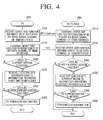
- FIG. 4 is a flow chart provided illustrating a method to control a video apparatus according to an exemplary embodiment of the present general inventive concept.
- the operation of the TV 200 is illustrated on the left side and the operation of the BD player 300 is illustrated on the right hand side of FIG. 4 .
- the TV 200 receives device information and information regarding functions of the BD player 300 from the BD player 300 via an image signal channel of a HDMI interface (S420).
- the image signal channel may be a TMDS signal channel of the HDMI standards, and device information and information regarding functions of the BD player 300 may be received in a SPD InfoFrame format.
- the TV 200 transmits device information and information regarding functions of the TV 200 to the BD player 300 via a data channel of the HDMI interface (S430).
- the data channel is a DDC of the HDMI standards, and device information and information regarding functions of the TV 200 is transmitted in a EDID format.
- the TV 200 determines whether the TV 200 supports certain functions (S450).
- the TV 200 If the TV 200 supports certain functions (S450-Y), the TV 200 reads out relevant bytes corresponding to the function information of the BD player 300 from the received SPD InfoFrame (S453). If the function information of the BD player 300 indicates that the BD player 300 supports the certain functions (S456-Y), the TV 200 performs the certain functions (S459).
- the BD player 300 transmits device information and information regarding functions of the BD player 300 to the TV 200 via an image signal channel of the HDMI interface (S410).
- the image signal channel may be a TMDS signal channel of the HDMI standards, and device information and function information of the BD player 300 may be transmitted in a SPD InfoFrame format.
- the BD player 300 receives device information and function information of the TV 200 from the TV 200 via a data channel of the HDMI interface (S440).
- the data channel may be a DDC of the HDMI standards, and device information and function information of the TV 200 may be received in the EDID format.
- the BD player 300 determines whether the BD player 300 supports certain functions (S460). If the BD player 300 supports certain functions (S460-Y), the BD player 300 reads out relevant bytes corresponding to the function information of the TV 200 from the received EDID (S463). If the function information of the TV 200 indicates that the TV 200 supports the certain functions (S466-Y), the BD player 300 performs the certain functions (S469).
- the TV 200 and the BD player 300 can identify whether certain functions are supported with each other, the TV 200 and the BD player 300 can execute optimum performance together.
- FIG. 5 is a schematic view illustrating HDMI interface channels in detail according to an exemplary embodiment of the present general inventive concept.
- the HDMI interface transmitting terminal 310 and the HDMI interface receiving terminal 260 communicates with each other via an HDMI cable.
- the HDMI interface includes a TMDS signal channel 262, DDC 264, consumer electronics control (CEC) 266 channel, and a hot plug detect (HPD) channel and power channel 268.
- CEC consumer electronics control
- HPD hot plug detect
- the transition minimized differential signaling (TMDS) signal channel 262 transmits a video signal, an audio signal, and an InfoFrame from the HDMI interface transmitting terminal 310 to the HDMI interface receiving terminal 260.
- the InfoFrame includes device information and function information of a device (i.e., the BD player 300) having the HDMI interface transmitting terminal 310.
- the display data channel is a channel to transmit data regarding encryption and enhanced display identification data (EDID).
- EDID enhanced display identification data
- the present general inventive concept is not limited thereto.
- the CEC 266 channel is a channel to transmit a control signal to control connected devices.
- the HPD channel 268 is a channel to detect a hot plug.
- the power channel 268 is a channel to supply power.
- HDMI channels TMDS signal channel 262 is a one-way communication channel, and DDC, CEC, and HPD channels are two-way communication channels.
- TMDS signal channel is used to transmit device information and function information of the BD player 300 to the TV 200
- DDC is used to transmit device information and function information of the TV 200 to the BD player 300.
- FIG. 6 is a table illustrating information on data bytes of SPD InfoFrame according to an exemplary embodiment of the present general inventive concept.
- SPD InfoFrame includes a total of 25 bytes, and a vendor name, a model name, and the product group of a device can be recorded in SPD InfoFrame.
- the 24 th data byte can indicate function information.
- FIG. 7 is a schematic view illustrating an example of SPD InfoFrame with information regarding BD player functions according to an exemplary embodiment of the present general inventive concept.
- a manufacturer name (a vendor name), "SAMSUNG” and a model name, "BD-P1600”, are recoded in SPD InfoFrame.
- the product group “0Ah” is "Blu-Ray Disc (BD)”
- the 24 th byte 700 indicates function information.
- the 24 th byte 700 may be "0" or “1”, and if it is “0”, that means a certain function is not supported, and if it is "1", that means a certain function is supported.
- the present general inventive concept is not limited thereto.
- device information and function information of the BD player 300 can be recorded using SPD InfoFrame.
- FIG. 8 is a table illustrating information corresponding to EDID bytes according to an exemplary embodiment of the present general inventive concept.
- a manufacturer name is recorded in 2 bytes, of which the address is 08h
- a model name is recorded in 2 bytes, of which the address is 0Ah. That is, the byte addresses for a model name are 0Ah and 0Bh.
- the function information of the TV 200 can be recorded in the address byte of 0Bh. This can be explained with reference to FIG. 9 .
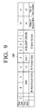
- FIG. 9 is a schematic view illustrating an example of an EDID having information on television functions.
- the model name "L3" is recorded in data byte A (that is, address 0Ah) of ID product code for the model name.
- "0" or “1” is recorded as function information of the TV 200 in data byte B 900 (that is, address 0Bh). If data byte B 900 is "0", that means the TV 200 does not support a certain function, and if data byte B 900 is "1", that means the TV 200 supports a certain function.
- device information and function information of the TV 200 can be recorded using EDID.
- the TV 200 and the BD player 300 may support a BD wise image quality mode as a certain function.
- the BD player 300 transmits an original image data to the TV 200 and the TV performs image processing on the received image.
- the BD player 300 If the BD player 300 is set to the BD wise mode, the BD player 300 transmits image data of which image quality is not adjusted to the TV 200 so that the TV 200 may adjust the quality of the image. If the TV 200 is set to the BD wise mode, the TV 200 receives image data of which image quality is not adjusted from the BD player 300 and adjusts the quality of the image. Adjusting image quality means performing image processing. Image mode adjustment includes deinterlacing, upscaling, back light adjustment, contrast, hue, saturation, noise reduction, cadence detection, white balance, resolution, and brightness. However the present general inventive concept is not limited thereto.
- a video processing apparatus mounted on the BD player 300 may have less performance than that of the A/V processing unit 220 of the TV 200.
- the A/V processing unit 220 of the TV 200 which have better performance performs image data processing, and as a result, a viewer may watch an image with better image quality.
- the TV 200 and the BD player 300 may determine whether the BD wise mode is supported with each other by going through the process illustrated above with reference to FIG. 4 . If both the TV 200 and the BD player 300 support the BD wise mode, the TV 200 and the BD player 300 may execute the BD wise mode. Accordingly, the TV 200 and the BD player 300 can automatically provide an image with better quality.
- FIG. 10 is a table illustrating whether a BD wise mode is executed depending on whether a BD wise mode of TV and BD is on or off.
- both the BD player 300 and the TV 200 execute the BD wise mode.
- the BD wise mode of the BD player 300 is off, the BD player 300 does not execute the BD wise mode and the TV 200 executes the BD wise mode only when the BD wise mode of the TV 200 is on.
- the TV 200 and the BD player 3300 may execute the BD wise mode in various ways, and accordingly a user may view an image with optimum quality.
- the TV 200 and the BD player 300 checks whether the BD wise mode is supported with each other, the TV 200 and the BD player 300 may execute the BD wise mode appropriately without separate manipulation by a user.
- a video apparatus is the TV 200, but any other video apparatus capable of receiving a HDMI interface, such as a monitor and notebook computer, can also be used.
- Video apparatus information is information regarding a video apparatus
- function information of a video apparatus is information regarding functions of a video apparatus.
- the apparatus connected to the video apparatus is the BD player 300, but any other AV apparatuses can also be connected.
- the apparatus connected to the video apparatus is the BD player 300, but any other AV apparatuses can also be connected.
- a set-top box, blue-ray player, or video player can be connected to the video apparatus.
- External apparatus information is information regarding apparatuses connected to the video apparatus
- function information of an external apparatus is information regarding functions of external apparatuses connected to the video apparatus.
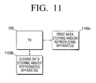
- FIG. 11 is a schematic view of a video system according to another exemplary embodiment of the present general inventive concept.
- the video system includes a television apparatus (TV) 200, a first data storing and/or reproducing apparatus 1110a, such as a Blue-ray Disk (BD) player 300 of FIG. 1 , and a second data storing and/or reproducing apparatus 1110b, such as another BD player 300 of FIG. 1 or data player.
- the TV 200 may select at least one of the first data storing and/or reproducing apparatus 1110a or the second data storing and/or reproducing apparatus 1110b to generate image and sound according to signals (data) received from the corresponding data storing and/or reproducing apparatus 1110a and 1110b by using the interface to communicate with the TV 200 as described above.
- the present general inventive concept can also be embodied as computer-readable codes on a computer-readable medium.
- the computer-readable medium can include a computer-readable recording medium and a computer-readable transmission medium.
- the computer-readable recording medium is any data storage device that can store data which can be thereafter read by a computer system. Examples of the computer-readable recording medium include read-only memory (ROM), random-access memory (RAM), CD-ROMs, magnetic tapes, floppy disks, and optical data storage devices.
- the computer-readable recording medium can also be distributed over network coupled computer systems so that the computer-readable code is stored and executed in a distributed fashion.
- the computer-readable transmission medium can transmit carrier waves or signals (e.g., wired or wireless data transmission through the Internet). Also, functional programs, codes, and code segments to accomplish the present general inventive concept can be easily construed by programmers skilled in the art to which the present general inventive concept pertains.
Landscapes
- Engineering & Computer Science (AREA)
- Physics & Mathematics (AREA)
- Computer Hardware Design (AREA)
- General Physics & Mathematics (AREA)
- Theoretical Computer Science (AREA)
- Two-Way Televisions, Distribution Of Moving Picture Or The Like (AREA)
Abstract
Description
- This application claims priority under 35 U.S.C. § 119(a) from Korean Patent Application No.
2008-109520, filed on November 5, 2008 2009-40777, filed on May 11, 2009 - The present general inventive concept relates to a video apparatus and a method to control the video apparatus, and more particularly, to a video apparatus to control functions using an A/V interface capable of two-way communication and a method for controlling the video apparatus thereof.
- With the development of technology regarding a video apparatus, televisions and audio/visual (AV) devices connected to televisions have become increasingly diverse. In particular, a size of a television screen has become larger and more diverse, and different image quality modes may be provided according to different contents such as a movie or a broadcasting program.
- As the functions of television have become diverse, and the functions of AV devices connected to televisions have improved, a user can watch an image with higher image quality and higher quality than ever before. In addition, a user can use a home theater system to enjoy a theater-like atmosphere at home.
- However, diverse televisions and diverse AV devices connected to televisions have made it more difficult for a user to identify a function of each device and to identify which function provides optimum image quality between the television and the AV device.
- A user desires to watch high-quality images, and therefore a method to automatically select appropriate functions for televisions and external AV devices is needed.
- The present general inventive concept provides a video apparatus to receive information regarding an external device and external device function from the external device via an interface, and transmit information regarding the video apparatus and video apparatus function to the external device and a method to control the video apparatus thereof.
- The present general inventive concept also provides a video apparatus to transmit information regarding video apparatus and video apparatus functions to an external device via an image signal channel and to receive information regarding the external devices and external device functions from the external device via a data channel of interface and a method to control the video apparatus thereof.
- Additional features and/or utilities of the present general inventive concept will be set forth in part in the description which follows and, in part, will be obvious from the description, or may be learned by practice of the general inventive concept.
- The foregoing and/or other features and utilities of the present general inventive concept may be achieved by providing a video apparatus connectable to an external apparatus which includes an interface connectable to the external apparatus and a control unit to transmit apparatus and function information of the video apparatus to the external apparatus and to receive device and function information of the external apparatus from the external apparatus, wherein the function information of the video apparatus includes information regarding whether the video apparatus supports a certain function, wherein the function information of the external apparatus includes information regarding whether the external apparatus supports a certain function, and wherein the control unit executes the certain function if the external apparatus and the video apparatus supports the certain function.
- The certain function may include functions regarding an image quality mode of an image.
- According to the certain function, the video apparatus may receive data of which an image quality is not adjusted from the external apparatus and may adjust an image quality of the image.
- In the image quality mode, at least one of resolution, sharpness, brightness, noise reduction, hue, and saturation may be adjusted.
- The interface may be high definition multimedia interface (HDMI) interface.
- The external apparatus may be received in a source product description (SPD) InfoFrame format, and the function information of the external apparatus may be included in at least one data byte included in the SPD InfoFrame.
- The control unit may transmit the information of the video apparatus to the external apparatus in an enhanced display identification data (EDID) format, and may record and transmit the function information of the video apparatus in at least one byte included in the EDID.
- The foregoing and/or other features and utilities of the present general inventive concept may also be achieved by providing a method to control a video system in which a video apparatus is connectable to an external apparatus via an interface which includes transmitting apparatus and function information of the video apparatus to the external apparatus, receiving apparatus and function information of the external apparatus, and executing a certain function if the external apparatus and the video apparatus support the certain function, wherein the function information of the video apparatus includes information regarding whether the video apparatus supports the certain function and wherein the function information of the external apparatus includes information regarding whether the external apparatus supports the certain function.
- The certain function may include a function related to an image quality mode of an image.
- In the executing the certain function, the video apparatus may receive data of which an image quality mode is not adjusted from the external apparatus and may adjust the image quality mode of the image.
- The image quality mode may adjust at least one of resolution, sharpness, brightness, noise reduction, hue, and saturation.
- The receiving may receive the information regarding device and function of the external apparatus via an image signal channel of the interface, and the transmitting may transmit information regarding device and function of the video apparatus to the external apparatus via a data channel of the interface.
- The interface may be high definition multimedia interface (HDMI).
- The image signal channel may be a transition minimized differential signaling (TMDS) of the HDMI interface and the data channel may be a display data channel (DDC) of the HDMI interface.
- The foregoing and/or other features and utilities of the present general inventive concept may also be achieved by providing an external apparatus connectable to a video apparatus which includes an interface connectable to the video apparatus and a control unit to transmit information regarding apparatus and function of the external apparatus to the video apparatus and to receive apparatus and function information of the video apparatus from the video apparatus, wherein the function information of the external apparatus includes information regarding whether the external apparatus supports a certain function and the function information of the video apparatus includes information regarding whether the video apparatus supports the certain function, and wherein the control unit executes the certain function if the external apparatus and the video apparatus support the certain function.
- The certain function may include a function related to an image quality mode of an image.
- According to the certain function, the external apparatus data of which an image quality is not adjusted may be transmitted to the video apparatus so that the video apparatus may adjust the image quality mode of the image.
- The image quality mode may adjust at least one of resolution, sharpness, brightness, noise reduction, hue, and saturation.
- The foregoing and/or other features and utilities of the present general inventive concept may also be achieved by providing a method to control a video system in which an external apparatus is connectable to a video apparatus via an interface which includes transmitting apparatus and function information of the external apparatus to the video apparatus, receiving apparatus and function information of the video apparatus from the video apparatus and executing a certain function if the function information of the video apparatus indicates that the video apparatus supports the certain function and the external apparatus also supports the certain function, wherein the function information of the external apparatus includes information regarding whether the external apparatus supports the certain function, and wherein the function information of the video apparatus includes information regarding whether the video apparatus supports the certain function.
- The foregoing and/or other features and utilities of the present general inventive concept may also be achieved by providing a video apparatus which includes an interface to communicate with an external apparatus, and a control unit to transmit a first information of the video apparatus to the external apparatus and to receive a second information of the external apparatus, wherein the control unit executes a certain function if the first information corresponds to the second information.
- The first information may include a first device information and a first function information of the video apparatus.
- The second information may include a second device information and a second function information of the external apparatus.
- The control unit may execute the certain function if the first and second function information support the certain function.
- The interface may receive and transmit information signals and image data signals through HDMI interface channels, the information signals may include the first information and the second information, and the information signals may be transmitted between the image data signals.
- The foregoing and/or other features and utilities of the present general inventive concept may also be achieved by providing a computer readable storage medium containing a method of controlling a video apparatus connectable to an external device, the method including receiving first device information and first function information of the external device, comparing the first device information and the first function information with a second device information and a second function information of the video apparatus, and transmitting a signal to the video apparatus to execute a certain function when the first function information and the second function information support the certain function.
- These and/or other features and utilities of the present general inventive concept will become apparent and more readily appreciated from the following description of the exemplary embodiments, taken in conjunction with the accompanying drawings of which:
-
FIG. 1 is a schematic view of a video system according to an exemplary embodiment of the present general inventive concept; -
FIG. 2 is a block diagram illustrating a detailed structure of a television according to an exemplary embodiment of the present general inventive concept; -
FIG. 3 is a block diagram illustrating a structure of a BD player according to an exemplary embodiment of the present general inventive concept; -
FIG. 4 is a flow chart illustrating a method to control a video apparatus according to an exemplary embodiment of the present general inventive concept; -
FIG. 5 is a schematic view illustrating HDMI interface channels in detail according to an exemplary embodiment of the present general inventive concept; -
FIG. 6 is a table illustrating information corresponding to data bytes of SPD InfoFrame according to an exemplary embodiment of the present general inventive concept; -
FIG. 7 is a schematic view illustrating an example of SPD InfoFrame having information regarding BD player functions according to an exemplary embodiment of the present general inventive concept; -
FIG. 8 is a table illustrating information corresponding to EDID bytes in detail according to an exemplary embodiment of the present general inventive concept; -
FIG. 9 is a schematic view illustrating an example of an EDID having information regarding television functions; -
FIG. 10 is a table illustrating whether a BD wise mode is on or off depending on whether a BD wise mode of TV and BD is on or off; and -
FIG. 11 is a schematic view of a video system according to another exemplary embodiment of the present general inventive concept. - Reference will now be made in detail to the exemplary embodiments of the present general inventive concept, examples of which are illustrated in the accompanying drawings, wherein like reference numerals refer to the like elements throughout. The exemplary embodiments are described below in order to explain the present general inventive concept by referring to the figures.
-
FIG. 1 is a schematic view of a video system according to an exemplary embodiment of the present general inventive concept. - As illustrated in
FIG. 1 , the video system includes a television apparatus (TV) 200 and a data storing and reproducing apparatus, such as a Blue-ray Disk (BD)player 300 connectable to each other through an interface capable of two-way communication. AlthoughFIG. 1 illustrates theBD player 300 as the data storing and reproducing apparatus, the present general inventive concept is not limited thereto. - The interface connecting the TV 200 with the
BD player 300 may be a high definition multimedia interface (HDMI), since HDMI includes a channel capable of two-way communication. - However, the present general inventive concept is not limited thereto. That is, in alternative exemplary embodiments, any A/V interface capable of two-way communication may be applied.
- The
BD player 300 reads out image and sound signals recorded on the BD and transmits the image and sound signals to theTV 200. Such a device which provides image and sound signals is referred to as a source device based on HDMI standards. - The
BD player 300 regularly transmits information regarding the device (such as, the name of manufacturer, model, and etc.) and certain functions (such as, whether an image quality mode is supported) to theTV 200 through an image receiving channel to inform theTV 200 of information regarding theBD player 300 and certain functions that theBD player 300 supports. - In exemplary embodiments, the certain functions include at least one of a function regarding image quality mode of an image or a type of the image source. The examples of functions regarding image quality mode include screen ratio adjustment, brightness adjustment, and scaling. The examples of functions regarding image source include movie mode, news mode, drama mode, and etc. However, the present general inventive concept is not limited thereto.
- The
TV 200 receives an image signal and a sound signal from theBD player 300 and displays these signals on a display screen. The apparatus which receives image signals and sound signals and displays them on the display screen is called a sink device, based on HDMI standards. - The
TV 200 regularly transmits information regarding the device (i.e., device information) such as, the name of manufacturer, model, and etc. and certain functions (such as, whether image quality mode is supported) to theBD player 300 through a data channel to inform theBD player 300 of information regarding theTV 200 and which functions theTV 200 supports. However, the present general inventive concept is not limited thereto. - By sending and receiving their own device information and information regarding certain functions, the
TV 200 and theBD player 300 can confirm with each other whether to support a function to provide optimum image quality. In particular, theTV 200 and theBD player 300 can identify whether certain functions are supported based on function information received from each other, and therefore can execute optimum functions for each device. - The structure of the
TV 200 will be explained in detail with reference toFIG. 2 . - As illustrated in
FIG. 2 , theTV 200 includes abroadcasting receiving unit 210, an A/V processing unit 220, asound output unit 230, adisplay unit 240, astorage unit 250, a HDMIinterface receiving terminal 260, acontrol unit 270, and a remotecontrol receiving unit 280. - In exemplary embodiments, the
broadcasting receiving unit 210 receives wired or wireless broadcasting from a broadcasting station or a satellite and demodulates the broadcasting. However, the present general inventive concept is not limited thereto. - The A/
V processing unit 220 performs a signal processing such as a video decoding, video scaling, or audio decoding on the image signal and sound signal input from thebroadcasting receiving unit 210 and thecontrol unit 270. The A/V processing unit 220 output the image signal to thedisplay unit 240, and the sound signal to thesound output unit 230. - The
sound output unit 230 outputs the sound output from the A/V processing unit 220 through a speaker (not illustrated). - The
display unit 240 displays the image output from the A/V processing unit 220. In particular, thedisplay unit 240 displays an image showing a process of booting theTV 200 on a screen. - The
storage unit 250 stores the recorded image. Thestorage unit 250 may include a hard-disk, non-volatile memory, and flash memory. However, the present general inventive concept is not limited thereto. - The HDMI
interface receiving terminal 260 receives an image signal and a sound signal from theBD player 300 connected via a HDMI cable. The structure of the HDMIinterface receiving terminal 260 will be explained in detail with reference toFIG. 5 . - The remote
control receiving unit 280 receives a command by a user and transmits the command to thecontrol unit 270. - The
control unit 270 identifies the user's command based on the manipulation received from theremote control 290, and controls comprehensive operation of theTV 200 according to the identified command. - The
control unit 270 receives device information and function information of theBD player 300 from theBD player 300 via the HDMIinterface receiving terminal 260. Thecontrol unit 270 transmits the device information and function information of theTV 200 to theBD player 300 via the HDMIinterface receiving terminal 260. - Since the data channel of the HDMI interface is capable of two-way communication, the
control unit 260 transmits the device information and function information of theTV 200 through the data channel of the HDMIinterface receiving terminal 260. More specifically, thecontrol unit 260 transmits the device information and function information of theTV 200 through a HDMI interface display data channel (DDC) of the HDMIinterface receiving channel 260. - The
control unit 270 transmits device information of theTV 200 to theBD player 300 in an enhanced display identification data (EDID) format. Thecontrol unit 270 records function information of theTV 200 in at least one byte included in the EDID. Accordingly, thecontrol unit 270 transmits device information and function information of theTV 200 in the EDID format to theBD player 300. - The device information of the
TV 200 is system information of theTV 200 or information regarding specification, and includes information such as the name of manufacturer and the name of model of theTV 200. For example, the device information of theTV 200 may be "SAMSUNG", which is a manufacturer name, and "L3", which is a model name. However, the present general inventive concept is not limited thereto. - The function information of the
TV 200 represents information regarding whether certain functions are supported by theTV 200. The certain functions are functions regarding image quality of an image or the type of image source. In exemplary embodiments, the examples of functions regarding image quality mode include screen ratio adjustment, brightness adjustment, and scaling. In exemplary embodiments, examples of functions regarding image source include movie mode, news mode, drama mode, and etc. However, the present general inventive concept is not limited thereto. - More specifically, the function information of the
TV 200 may be recorded in bytes, of which the address is 0Bh in the EDID. If the byte of address 0Bh is 1, that means theTV 200 supports certain functions, and if the byte of address 0Bh is 0, that means theTV 200 does not support certain functions. - The EDID format including function information will be explained with reference to
FIGS. 8 and9 . - The
control unit 270 receives device information and function information of theBD player 300 from theBD player 300 through an image signal channel of the HDMIinterface receiving terminal 260. The image signal channel may be a transition minimized differential signaling (TMDS) signal of the HDMI interface. However, the present general inventive concept is not limited thereto. - The
control unit 270 receives device information of theBD player 300 in a source product description (SPD) InfoFrame format. The function information of theBD player 300 is recorded in at least one byte included in the SPD InfoFrame. Accordingly, thecontrol unit 270 determines whether certain functions are supported by theBD player 300. - The device information of the
BD player 300 is system information of theBD player 300 or information regarding specification, and includes information such as the name of manufacturer and name of model of theBD player 300. For example, the device information of theBD player 300 may be "SAMSUNG", which is a manufacturer name, and "BD-1600", which is a model name. - The function information of the
BD player 300 represents information regarding whether certain functions are supported by theBD player 300. The certain functions are functions regarding image quality of an image or the type of image source. In exemplary embodiments, the examples of functions regarding image quality mode include screen ratio adjustment, brightness adjustment, and scaling. In exemplary embodiments, examples of functions regarding image source include movie mode, news mode, drama mode, and etc. However, the present general inventive concept is not limited thereto. - More specifically, function information of the
BD player 300 may be recorded in the 24th byte of the SPD InfoFrame. If the 24th byte is 1, that means theBD player 300 supports certain functions, but if the 24th byte is 0, that means theBD player 300 does not support certain functions. - The SPID InfoFrame format including function information will be explained with reference to
FIGS. 6 and7 . - If the function information indicates that the
BD player 300 supports certain functions and theTV 200 also supports the same certain functions, thecontrol unit 270 executes the certain functions. For instance, if both theTV 200 and theBD player 300 support a wide screen mode, theTV 200 checks function information of theBD player 300 received when theBD player 300 is connected to theTV 200 and executes the wide screen mode. - By receiving function information from the
BD player 300, theTV 200 is able to execute optimum functions in combination with theBD player 300. By receiving function information as well as device information of theBD player 300, theTV 200 is able to execute functions appropriate to theBD player 300. As theTV 200 transmits the device information and function information of theTV 200, theBD player 300 is also able to execute functions appropriate to theTV 200. - The structure of the
BD player 300 will be explained in detail with reference toFIG. 3 FIG. 3 , is a block diagram illustrating a structure of theBD player 300 according to an exemplary embodiment of the present general inventive concept. As illustrated inFIG. 3 , theBD player 300 includes a HDMIinterface transmitting terminal 310, acontrol unit 320, and a BDplayer function unit 330. - The BD
player function unit 330 executes usual functions as a BD player. For instance, the BDplayer function unit 330 reads out an image and sound signal of an inserted BD and transmits the signals to theTV 200, which is connected to the BD player. - The HDMI
interface transmitting terminal 310 is connected to theTV 200 through a HDMI cable. The HDMI interface transmitting terminal 310 transmits the image and sound signals read out from the BD to theTV 200. The HDMIinterface transmitting terminal 310 will be explained in detail with reference toFIG. 5 . - The
control unit 320 transmits device information and function information of theBD player 300 to theTV 200 through an image signal channel of the HDMIinterface transmitting terminal 310. Thecontrol unit 320 receives device information and function information of theTV 200 from theTV 200 through a data channel of the HDMIinterface transmitting terminal 310. - The image signal channel may be a TMDS signal channel of the HDMI interface and the data channel may be a DDC of the HDMI interface. However, the present general inventive concept is not limited thereto. The function information of the
BD player 300 includes information regarding whether theBD player 300 supports certain functions. The function information of theTV 200 includes information regarding whether theTV 200 supports certain functions. - The
control unit 320 receives device information of theTV 200 from theTV 200 in the EDID format. The function information of theTV 200 is recorded at least one byte included in the EDID. Accordingly, thecontrol unit 270 receives both device information and function information of theTV 200 from theTV 200 in the EDID format. - The device information of the
TV 200 is system information of theTV 200 or information regarding specification, and includes information such as the name of manufacturer and name of model of theTV 200. For example, the device information of theTV 200 may be "SAMSUNG", which is a manufacturer name, and "BD-1600", which is a model name. - The function information of the
TV 200 represents information regarding whether certain functions are supported by theTV 200. The certain functions are functions regarding image quality of an image or the type of image source of theTV 200. In exemplary embodiments, the examples of functions regarding image quality mode include screen ratio adjustment, brightness adjustment, and scaling. In further exemplary embodiments, the examples of functions regarding image source include movie mode, news mode, drama mode, and etc. However, the present general inventive concept is not limited thereto. - More specifically, the function information of the
TV 200 may be recorded in bytes, of which the address is 0Bh in the EDID. If the byte of address 0Bh is 1, that means theTV 200 supports certain functions, and if the byte of address 0Bh is 0, that means theTV 200 does not support certain functions. - The EDID format including function information will be explained with reference to
FIGS. 8 and9 . - The
control unit 320 transmits device information and function information of theBD player 300 to theTV 200 through an image signal channel of the HDMIinterface transmitting terminal 310. The image signal channel may be a transition minimized differential signaling (TMDS) signal of the HDMI interface. - The
control unit 320 transmits device information of theBD player 300 in a source product description (SPD) InfoFrame format. The function information of theBD player 300 is recorded in at least one byte included in the SPD InfoFrame. Accordingly, thecontrol unit 320 may transmit function information of theBD player 300 along with device information of theBD player 300 to theTV 200. - The device information of the
BD player 300 is system information of theBD player 300 or information regarding specification, and includes information such as the name of manufacturer and the name of model of theBD player 300. For example, the device information of theBD player 300 may be "SAMSUNG", which is a manufacturer name, and "L3", which is a model name. - The function information of the
BD player 300 is information regarding whether certain functions are supported by theBD player 300. The certain functions include functions regarding image quality mode of an image or the type of image source of theBD player 300. In exemplary embodiments, the examples of functions regarding image quality mode include screen ratio adjustment, brightness adjustment, and scaling. In exemplary embodiments, the examples of functions regarding image source include movie mode, news mode, drama mode, and etc. - More specifically, the function information of the
BD player 300 may be recorded in the 24th byte of the SPD InfoFrame. If the 24th byte is 1, that means theBD player 300 supports certain functions, but if the 24th byte is 0, that means theBD player 300 does not support certain functions. - The SPID InfoFrame format including function information will be explained with reference to
FIGS. 6 and7 . - If the function information indicates that the
TV 200 supports certain functions and theBD player 300 also supports certain functions, thecontrol unit 320 executes the certain functions. For instance, if both theTV 200 and theBD player 300 support a wide screen mode, theBD player 300 checks function information of theTV 200 received when theTV 200 is connected to theBD player 300 and executes the wide screen mode on theTV 200. - By receiving function information from the
TV 200, theBD player 300 is able to execute optimum functions in combination with theTV 200. By receiving function information as well as device information of theTV 200, theBD player 300 is able to execute functions appropriate to the type of theTV 200. As theBD player 300 transmits its own device information and function information to theTV 200, theTV 200 is also able to execute functions appropriate to theBD player 300. - The method of controlling the
TV 200 and theBD player 300, which are connectable to each other via the HDMI interface, will be explained with reference toFIG. 4. FIG. 4 is a flow chart provided illustrating a method to control a video apparatus according to an exemplary embodiment of the present general inventive concept. - The operation of the
TV 200 is illustrated on the left side and the operation of theBD player 300 is illustrated on the right hand side ofFIG. 4 . - As for the operation of the
TV 200, theTV 200 receives device information and information regarding functions of theBD player 300 from theBD player 300 via an image signal channel of a HDMI interface (S420). The image signal channel may be a TMDS signal channel of the HDMI standards, and device information and information regarding functions of theBD player 300 may be received in a SPD InfoFrame format. - The
TV 200 transmits device information and information regarding functions of theTV 200 to theBD player 300 via a data channel of the HDMI interface (S430). The data channel is a DDC of the HDMI standards, and device information and information regarding functions of theTV 200 is transmitted in a EDID format. - The
TV 200 determines whether theTV 200 supports certain functions (S450). - If the
TV 200 supports certain functions (S450-Y), theTV 200 reads out relevant bytes corresponding to the function information of theBD player 300 from the received SPD InfoFrame (S453). If the function information of theBD player 300 indicates that theBD player 300 supports the certain functions (S456-Y), theTV 200 performs the certain functions (S459). - As for the operation of the
BD player 300, theBD player 300 transmits device information and information regarding functions of theBD player 300 to theTV 200 via an image signal channel of the HDMI interface (S410). The image signal channel may be a TMDS signal channel of the HDMI standards, and device information and function information of theBD player 300 may be transmitted in a SPD InfoFrame format. - The
BD player 300 receives device information and function information of theTV 200 from theTV 200 via a data channel of the HDMI interface (S440). The data channel may be a DDC of the HDMI standards, and device information and function information of theTV 200 may be received in the EDID format. - The
BD player 300 determines whether theBD player 300 supports certain functions (S460). If theBD player 300 supports certain functions (S460-Y), theBD player 300 reads out relevant bytes corresponding to the function information of theTV 200 from the received EDID (S463). If the function information of theTV 200 indicates that theTV 200 supports the certain functions (S466-Y), theBD player 300 performs the certain functions (S469). - Since the
TV 200 and theBD player 300 can identify whether certain functions are supported with each other, theTV 200 and theBD player 300 can execute optimum performance together. - The channel of the HDMI interface will be explained with reference to
FIG. 5. FIG. 5 is a schematic view illustrating HDMI interface channels in detail according to an exemplary embodiment of the present general inventive concept. - The HDMI
interface transmitting terminal 310 and the HDMIinterface receiving terminal 260 communicates with each other via an HDMI cable. As illustrated inFIG. 5 , the HDMI interface includes aTMDS signal channel 262,DDC 264, consumer electronics control (CEC) 266 channel, and a hot plug detect (HPD) channel andpower channel 268. - The transition minimized differential signaling (TMDS)
signal channel 262 transmits a video signal, an audio signal, and an InfoFrame from the HDMI interface transmitting terminal 310 to the HDMIinterface receiving terminal 260. The InfoFrame includes device information and function information of a device (i.e., the BD player 300) having the HDMIinterface transmitting terminal 310. - The display data channel (DDC) is a channel to transmit data regarding encryption and enhanced display identification data (EDID). However the present general inventive concept is not limited thereto.
- The
CEC 266 channel is a channel to transmit a control signal to control connected devices. TheHPD channel 268 is a channel to detect a hot plug. Thepower channel 268 is a channel to supply power. Among HDMI channels,TMDS signal channel 262 is a one-way communication channel, and DDC, CEC, and HPD channels are two-way communication channels. - Among HDMI interface channels, TMDS signal channel is used to transmit device information and function information of the
BD player 300 to theTV 200, and DDC is used to transmit device information and function information of theTV 200 to theBD player 300. - The specification of SPD InforFrame and the location of bytes where function information is recorded will be explained with reference to
FIGS. 6 and7 .FIG. 6 is a table illustrating information on data bytes of SPD InfoFrame according to an exemplary embodiment of the present general inventive concept. - As illustrated in
FIG. 6 , SPD InfoFrame includes a total of 25 bytes, and a vendor name, a model name, and the product group of a device can be recorded in SPD InfoFrame. The 24th data byte can indicate function information. -
FIG. 7 is a schematic view illustrating an example of SPD InfoFrame with information regarding BD player functions according to an exemplary embodiment of the present general inventive concept. - As illustrated in
FIG. 7 , a manufacturer name (a vendor name), "SAMSUNG" and a model name, "BD-P1600", are recoded in SPD InfoFrame. According to the table inFIG. 6 , the product group "0Ah" is "Blu-Ray Disc (BD)", and the 24thbyte 700 indicates function information. The 24thbyte 700 may be "0" or "1", and if it is "0", that means a certain function is not supported, and if it is "1", that means a certain function is supported. However the present general inventive concept is not limited thereto. - Other values in addition to "0" and "1" can be used to indicate whether a certain function is supported. One of many values for various functions other than information indicating whether a certain function is supported can be recorded in a byte for function information. The function information can be recorded in other bytes as well as in the 24th
byte 700. - As such, device information and function information of the
BD player 300 can be recorded using SPD InfoFrame. - The location where information regarding the specification of EDID and function is recorded will be explained with reference to
FIGS. 8 and9 .FIG. 8 is a table illustrating information corresponding to EDID bytes according to an exemplary embodiment of the present general inventive concept. As illustrated inFIG. 8 , in EDID, a manufacturer name is recorded in 2 bytes, of which the address is 08h, and a model name is recorded in 2 bytes, of which the address is 0Ah. That is, the byte addresses for a model name are 0Ah and 0Bh. The function information of theTV 200 can be recorded in the address byte of 0Bh. This can be explained with reference toFIG. 9 . -
FIG. 9 is a schematic view illustrating an example of an EDID having information on television functions. - As illustrated in
FIG. 9 , the model name "L3" is recorded in data byte A (that is, address 0Ah) of ID product code for the model name. In exemplary embodiments, "0" or "1" is recorded as function information of theTV 200 in data byte B 900 (that is, address 0Bh). Ifdata byte B 900 is "0", that means theTV 200 does not support a certain function, and ifdata byte B 900 is "1", that means theTV 200 supports a certain function. - Other values in addition to "0" and "1" can be used to indicate whether a certain function is supported. One of many values for various functions other than information indicating whether a certain function is supported can be recorded in a byte for function information. The function information can be recorded in other bytes as well as in
data byte B 900. - As such, in exemplary embodiments, device information and function information of the
TV 200 can be recorded using EDID. - An example of certain functions supported by the
TV 200 and theBD player 300 together will be explained. TheTV 200 and theBD player 300 may support a BD wise image quality mode as a certain function. In the BD wise image quality mode, theBD player 300 transmits an original image data to theTV 200 and the TV performs image processing on the received image. - If the
BD player 300 is set to the BD wise mode, theBD player 300 transmits image data of which image quality is not adjusted to theTV 200 so that theTV 200 may adjust the quality of the image. If theTV 200 is set to the BD wise mode, theTV 200 receives image data of which image quality is not adjusted from theBD player 300 and adjusts the quality of the image. Adjusting image quality means performing image processing. Image mode adjustment includes deinterlacing, upscaling, back light adjustment, contrast, hue, saturation, noise reduction, cadence detection, white balance, resolution, and brightness. However the present general inventive concept is not limited thereto. - A video processing apparatus mounted on the
BD player 300 may have less performance than that of the A/V processing unit 220 of theTV 200. In this case, if theBD player 300 and theTV 200 execute the BD wise mode, the A/V processing unit 220 of theTV 200 which have better performance performs image data processing, and as a result, a viewer may watch an image with better image quality. - The
TV 200 and theBD player 300 may determine whether the BD wise mode is supported with each other by going through the process illustrated above with reference toFIG. 4 . If both theTV 200 and theBD player 300 support the BD wise mode, theTV 200 and theBD player 300 may execute the BD wise mode. Accordingly, theTV 200 and theBD player 300 can automatically provide an image with better quality. - Even if the
TV 200 and theBD player 300 support the BD wise mode, whether to execute the BD wise mode may be determined depending on whether the function is on or off. - This will be explained with reference to
FIG. 10. FIG. 10 is a table illustrating whether a BD wise mode is executed depending on whether a BD wise mode of TV and BD is on or off. - As illustrated in
FIG. 10 , when the BD wise mode of theBD player 300 is on, both theBD player 300 and theTV 200 execute the BD wise mode. However, if the BD wise mode of theBD player 300 is off, theBD player 300 does not execute the BD wise mode and theTV 200 executes the BD wise mode only when the BD wise mode of theTV 200 is on. - As such, the
TV 200 and the BD player 3300 may execute the BD wise mode in various ways, and accordingly a user may view an image with optimum quality. In addition, since theTV 200 and theBD player 300 checks whether the BD wise mode is supported with each other, theTV 200 and theBD player 300 may execute the BD wise mode appropriately without separate manipulation by a user. - In the exemplary embodiment of the present general inventive concept, a video apparatus is the
TV 200, but any other video apparatus capable of receiving a HDMI interface, such as a monitor and notebook computer, can also be used. - Video apparatus information is information regarding a video apparatus, and function information of a video apparatus is information regarding functions of a video apparatus.
- In exemplary embodiments of the present general inventive concept, the apparatus connected to the video apparatus is the
BD player 300, but any other AV apparatuses can also be connected. For instance, other than theBD player 300, a set-top box, blue-ray player, or video player can be connected to the video apparatus. External apparatus information is information regarding apparatuses connected to the video apparatus, and function information of an external apparatus is information regarding functions of external apparatuses connected to the video apparatus. -
FIG. 11 is a schematic view of a video system according to another exemplary embodiment of the present general inventive concept. - As illustrated shown in
FIG. 11 , the video system includes a television apparatus (TV) 200, a first data storing and/or reproducing apparatus 1110a, such as a Blue-ray Disk (BD)player 300 ofFIG. 1 , and a second data storing and/or reproducing apparatus 1110b, such as anotherBD player 300 ofFIG. 1 or data player. In exemplary embodiments, theTV 200 may select at least one of the first data storing and/or reproducing apparatus 1110a or the second data storing and/or reproducing apparatus 1110b to generate image and sound according to signals (data) received from the corresponding data storing and/or reproducing apparatus 1110a and 1110b by using the interface to communicate with theTV 200 as described above. - The present general inventive concept can also be embodied as computer-readable codes on a computer-readable medium. The computer-readable medium can include a computer-readable recording medium and a computer-readable transmission medium. The computer-readable recording medium is any data storage device that can store data which can be thereafter read by a computer system. Examples of the computer-readable recording medium include read-only memory (ROM), random-access memory (RAM), CD-ROMs, magnetic tapes, floppy disks, and optical data storage devices. The computer-readable recording medium can also be distributed over network coupled computer systems so that the computer-readable code is stored and executed in a distributed fashion. The computer-readable transmission medium can transmit carrier waves or signals (e.g., wired or wireless data transmission through the Internet). Also, functional programs, codes, and code segments to accomplish the present general inventive concept can be easily construed by programmers skilled in the art to which the present general inventive concept pertains.
- Although a few exemplary embodiments of the present general inventive concept have been shown and described, it will be appreciated by those skilled in the art that changes may be made in these exemplary embodiments without departing from the principles and spirit of the general inventive concept, the scope of which is defined in the appended claims and their equivalents.
Claims (15)
- A video apparatus connectable to an external apparatus, comprising:an interface connectable to the external apparatus; anda control unit to transmit apparatus and function information of the video apparatus to the external apparatus and to receive device and function information of the external apparatus,wherein the function information of the video apparatus includes information regarding whether the video apparatus supports a certain function,wherein the function information of the external apparatus includes information regarding whether the external apparatus supports a certain function, andwherein the control unit executes the certain function if the external apparatus and the video apparatus supports the certain function.
- The video apparatus of claim 1, wherein the certain function includes functions regarding an image quality mode of an image.
- The video apparatus of claim 1 or 2, wherein, according to the certain function, the video apparatus receives data of which an image quality is not adjusted from the external apparatus and adjusts image quality of the image.
- The video apparatus of claim 2, wherein in the image quality mode, at least one of resolution, sharpness, brightness, noise reduction, hue, and saturation is adjusted.
- The video apparatus of any one of claims 1 to 4, wherein the interface is high definition multimedia interface (HDMI) interface.
- The video apparatus of any one of claims 1 to 5, wherein the external apparatus is received in a source product description (SPD) InfoFrame format, and the function information of the external apparatus is included in at least one data byte included in the SPD InfoFrame.
- The video apparatus of any one of claims 1 to 6, wherein the control unit transmits the information of the video apparatus to the external apparatus in a enhanced display identification data (EDID) format and records and transmits the function information of the video apparatus in at least one byte included in the EDID.
- A method to control a video system in which a video apparatus is connectable to an external apparatus via an interface, the method comprising:transmitting apparatus and function information of the video apparatus to the external apparatus;receiving apparatus and function information of the external apparatus; andexecuting a certain function if the external apparatus and the video apparatus support the certain function,wherein the function information of the video apparatus includes information regarding whether the video apparatus supports the certain function, andwherein the function information of the external apparatus includes information regarding whether the external apparatus supports the certain function.
- The method of claim 8, wherein the certain function includes a function related to an image quality mode of an image.
- The method of claim 8 or 9, wherein in the executing the certain function, the video apparatus receives data of which image quality mode is not adjusted from the external apparatus and adjusts the image quality mode of the image.
- The method of claim 9, wherein the image quality mode adjusts at least one of resolution, sharpness, brightness, noise reduction, hue and saturation.
- The method of any one of claims 8 to 11, wherein the receiving receives the information regarding device and function of the external apparatus via an image signal channel of the interface, and
the transmitting transmits information regarding device and function of the video apparatus to the external apparatus via a data channel of the interface. - The method of claim 12, wherein the interface is high definition multimedia interface (HDMI).
- The method of claim 12 or 13, wherein the image signal channel is a transition minimized differential signaling (TMDS) of the HDMI interface and the data channel is a display data channel (DDC) of the HDMI interface.
- A computer readable storage medium containing a method of controlling a video apparatus connectable to an external device, the method comprising:receiving first device information and first function information of the external device;comparing the first device information and the first function information with a second device information and a second function information of the video apparatus; andtransmitting a signal to the video apparatus to execute a certain function when the first function information and the second function information support the certain function.
Applications Claiming Priority (2)
| Application Number | Priority Date | Filing Date | Title |
|---|---|---|---|
| KR20080109520 | 2008-11-05 | ||
| KR1020090040777A KR20100050373A (en) | 2008-11-05 | 2009-05-11 | Video apparatus and method for controlling video apparatus |
Publications (2)
| Publication Number | Publication Date |
|---|---|
| EP2187382A2 true EP2187382A2 (en) | 2010-05-19 |
| EP2187382A3 EP2187382A3 (en) | 2010-12-15 |
Family
ID=41571310
Family Applications (1)
| Application Number | Title | Priority Date | Filing Date |
|---|---|---|---|
| EP09173279A Withdrawn EP2187382A3 (en) | 2008-11-05 | 2009-10-16 | Video apparatus and method of controlling the video apparatus |
Country Status (2)
| Country | Link |
|---|---|
| US (1) | US20100110292A1 (en) |
| EP (1) | EP2187382A3 (en) |
Cited By (2)
| Publication number | Priority date | Publication date | Assignee | Title |
|---|---|---|---|---|
| WO2015008448A1 (en) * | 2013-07-16 | 2015-01-22 | Sony Corporation | Information processing apparatus, information recording medium, information processing method, and program |
| EP3089464A1 (en) * | 2015-04-29 | 2016-11-02 | Samsung Electronics Co., Ltd. | Source device and control method thereof, and sink device and image quality improvement processing method thereof |
Families Citing this family (2)
| Publication number | Priority date | Publication date | Assignee | Title |
|---|---|---|---|---|
| JP2010193247A (en) * | 2009-02-19 | 2010-09-02 | Sanyo Electric Co Ltd | Hdmi apparatus |
| WO2020171245A1 (en) * | 2019-02-18 | 2020-08-27 | 엘지전자 주식회사 | Display device and method for operating same |
Citations (2)
| Publication number | Priority date | Publication date | Assignee | Title |
|---|---|---|---|---|
| KR20080109520A (en) | 2007-06-13 | 2008-12-17 | 삼성전자주식회사 | Terminal and method for playing music thereof |
| KR20090040777A (en) | 2007-10-22 | 2009-04-27 | 손형모 | Filling up equipments for reinforcing the ground of dipping work |
Family Cites Families (8)
| Publication number | Priority date | Publication date | Assignee | Title |
|---|---|---|---|---|
| KR100565058B1 (en) * | 2003-08-22 | 2006-03-30 | 삼성전자주식회사 | Digital versatile disc player for setting optimum display environment and method for operating digital versatile disc player of the same |
| JP2007150853A (en) * | 2005-11-29 | 2007-06-14 | Toshiba Corp | Feeder, processor, and instruction method |
| EP1995952A4 (en) * | 2006-03-03 | 2010-05-19 | Panasonic Corp | Transmitting device, receiving device and transmitting/receiving device |
| CN101331771B (en) * | 2006-05-16 | 2010-07-28 | 索尼株式会社 | Communication system, transmission device, reception device, communication method |
| JP2008005168A (en) * | 2006-06-21 | 2008-01-10 | Toshiba Corp | Information processor and display control method |
| US20080133249A1 (en) * | 2006-11-30 | 2008-06-05 | Hashiguchi Kohei | Audio data transmitting device and audio data receiving device |
| US8392958B2 (en) * | 2007-03-13 | 2013-03-05 | Sony Corporation | Communication system, transmission apparatus, transmission method, reception apparatus and reception method |
| JP4479776B2 (en) * | 2007-10-05 | 2010-06-09 | ソニー株式会社 | Display device and transmission device |
-
2009
- 2009-10-16 EP EP09173279A patent/EP2187382A3/en not_active Withdrawn
- 2009-10-30 US US12/609,291 patent/US20100110292A1/en not_active Abandoned
Patent Citations (2)
| Publication number | Priority date | Publication date | Assignee | Title |
|---|---|---|---|---|
| KR20080109520A (en) | 2007-06-13 | 2008-12-17 | 삼성전자주식회사 | Terminal and method for playing music thereof |
| KR20090040777A (en) | 2007-10-22 | 2009-04-27 | 손형모 | Filling up equipments for reinforcing the ground of dipping work |
Cited By (8)
| Publication number | Priority date | Publication date | Assignee | Title |
|---|---|---|---|---|
| WO2015008448A1 (en) * | 2013-07-16 | 2015-01-22 | Sony Corporation | Information processing apparatus, information recording medium, information processing method, and program |
| CN105359543A (en) * | 2013-07-16 | 2016-02-24 | 索尼公司 | Information processing apparatus, information recording medium, information processing method, and program |
| CN105359543B (en) * | 2013-07-16 | 2019-10-25 | 索尼公司 | Information processing equipment, information recording carrier, information processing method and program |
| EP3089464A1 (en) * | 2015-04-29 | 2016-11-02 | Samsung Electronics Co., Ltd. | Source device and control method thereof, and sink device and image quality improvement processing method thereof |
| CN107548558A (en) * | 2015-04-29 | 2018-01-05 | 三星电子株式会社 | Source device and its control method and place device and its image quality improvement processing method |
| US10574957B2 (en) | 2015-04-29 | 2020-02-25 | Samsung Electronics Co., Ltd. | Source device and control method thereof, and sink device and image quality improvement processing method thereof |
| CN107548558B (en) * | 2015-04-29 | 2022-03-08 | 三星电子株式会社 | Source apparatus, control method thereof, sink apparatus, and image quality improvement processing method thereof |
| US11350069B2 (en) | 2015-04-29 | 2022-05-31 | Samsung Electronics Co., Ltd. | Source device and control method thereof, and sink device and image quality improvement processing method thereof |
Also Published As
| Publication number | Publication date |
|---|---|
| US20100110292A1 (en) | 2010-05-06 |
| EP2187382A3 (en) | 2010-12-15 |
Similar Documents
| Publication | Publication Date | Title |
|---|---|---|
| US8199161B2 (en) | Image processing device and image processing method | |
| US9179087B2 (en) | AV device | |
| US8340499B2 (en) | Recording control apparatus and control method for the same | |
| CN107256702B (en) | Video transmitter, video receiver and television | |
| US8966566B2 (en) | Communication device, communication control method, and program | |
| US8717503B2 (en) | Audio output device connectable with plurality of devices and method of controlling the same | |
| US20060168131A1 (en) | Electronic device and method for supporting different display modes | |
| US20110043707A1 (en) | Content transmitting device | |
| JP4468142B2 (en) | Data relay device, data relay method, and data transmission system | |
| US20080098318A1 (en) | Method for providing menu screen suitable for menus provided by external device and imaging device using the same | |
| JP2009027601A (en) | Display system | |
| EP2187382A2 (en) | Video apparatus and method of controlling the video apparatus | |
| US20110128437A1 (en) | Image signal processing apparatus for detaching a plurality of modules and control method thereof | |
| JP2007214830A (en) | Video output device | |
| JP2008028950A (en) | Display apparatus, acoustic apparatus, av system, and sound reproducing method | |
| JP2008028947A (en) | Display apparatus and display system | |
| JP2010114895A (en) | Video equipment, control method of video equipment, and recording medium | |
| KR101437694B1 (en) | Display apparatus and control method thereof | |
| KR20100089328A (en) | A display device | |
| US20100046910A1 (en) | Media signal sink and method for playing image thereof | |
| KR101660730B1 (en) | Method for displaying of image and system for displaying of image thereof | |
| KR100850964B1 (en) | Display system including a display device and one or more devices to be connected the display device, and method for controlling the display system | |
| JP5689938B2 (en) | Video transmission equipment | |
| JP2008167367A (en) | Transmission device | |
| JP2009044491A (en) | Image reproducer |
Legal Events
| Date | Code | Title | Description |
|---|---|---|---|
| PUAI | Public reference made under article 153(3) epc to a published international application that has entered the european phase |
Free format text: ORIGINAL CODE: 0009012 |
|
| AK | Designated contracting states |
Kind code of ref document: A2 Designated state(s): AT BE BG CH CY CZ DE DK EE ES FI FR GB GR HR HU IE IS IT LI LT LU LV MC MK MT NL NO PL PT RO SE SI SK SM TR |
|
| AX | Request for extension of the european patent |
Extension state: AL BA RS |
|
| PUAL | Search report despatched |
Free format text: ORIGINAL CODE: 0009013 |
|
| AK | Designated contracting states |
Kind code of ref document: A3 Designated state(s): AT BE BG CH CY CZ DE DK EE ES FI FR GB GR HR HU IE IS IT LI LT LU LV MC MK MT NL NO PL PT RO SE SI SK SM TR |
|
| AX | Request for extension of the european patent |
Extension state: AL BA RS |
|
| 17P | Request for examination filed |
Effective date: 20110615 |
|
| 17Q | First examination report despatched |
Effective date: 20110915 |
|
| RAP1 | Party data changed (applicant data changed or rights of an application transferred) |
Owner name: SAMSUNG ELECTRONICS CO., LTD. |
|
| STAA | Information on the status of an ep patent application or granted ep patent |
Free format text: STATUS: THE APPLICATION IS DEEMED TO BE WITHDRAWN |
|
| 18D | Application deemed to be withdrawn |
Effective date: 20130502 |