EP2186622A1 - Method for joining composite structural members and structural members made thereby - Google Patents
Method for joining composite structural members and structural members made thereby Download PDFInfo
- Publication number
- EP2186622A1 EP2186622A1 EP09176006A EP09176006A EP2186622A1 EP 2186622 A1 EP2186622 A1 EP 2186622A1 EP 09176006 A EP09176006 A EP 09176006A EP 09176006 A EP09176006 A EP 09176006A EP 2186622 A1 EP2186622 A1 EP 2186622A1
- Authority
- EP
- European Patent Office
- Prior art keywords
- composite
- joint
- sections
- splice member
- forming
- Prior art date
- Legal status (The legal status is an assumption and is not a legal conclusion. Google has not performed a legal analysis and makes no representation as to the accuracy of the status listed.)
- Withdrawn
Links
Images









Classifications
-
- B—PERFORMING OPERATIONS; TRANSPORTING
- B29—WORKING OF PLASTICS; WORKING OF SUBSTANCES IN A PLASTIC STATE IN GENERAL
- B29C—SHAPING OR JOINING OF PLASTICS; SHAPING OF MATERIAL IN A PLASTIC STATE, NOT OTHERWISE PROVIDED FOR; AFTER-TREATMENT OF THE SHAPED PRODUCTS, e.g. REPAIRING
- B29C70/00—Shaping composites, i.e. plastics material comprising reinforcements, fillers or preformed parts, e.g. inserts
- B29C70/04—Shaping composites, i.e. plastics material comprising reinforcements, fillers or preformed parts, e.g. inserts comprising reinforcements only, e.g. self-reinforcing plastics
- B29C70/28—Shaping operations therefor
- B29C70/40—Shaping or impregnating by compression not applied
- B29C70/42—Shaping or impregnating by compression not applied for producing articles of definite length, i.e. discrete articles
- B29C70/44—Shaping or impregnating by compression not applied for producing articles of definite length, i.e. discrete articles using isostatic pressure, e.g. pressure difference-moulding, vacuum bag-moulding, autoclave-moulding or expanding rubber-moulding
-
- B—PERFORMING OPERATIONS; TRANSPORTING
- B64—AIRCRAFT; AVIATION; COSMONAUTICS
- B64C—AEROPLANES; HELICOPTERS
- B64C1/00—Fuselages; Constructional features common to fuselages, wings, stabilising surfaces or the like
- B64C1/06—Frames; Stringers; Longerons ; Fuselage sections
-
- B—PERFORMING OPERATIONS; TRANSPORTING
- B23—MACHINE TOOLS; METAL-WORKING NOT OTHERWISE PROVIDED FOR
- B23K—SOLDERING OR UNSOLDERING; WELDING; CLADDING OR PLATING BY SOLDERING OR WELDING; CUTTING BY APPLYING HEAT LOCALLY, e.g. FLAME CUTTING; WORKING BY LASER BEAM
- B23K31/00—Processes relevant to this subclass, specially adapted for particular articles or purposes, but not covered by any single one of main groups B23K1/00 - B23K28/00
- B23K31/02—Processes relevant to this subclass, specially adapted for particular articles or purposes, but not covered by any single one of main groups B23K1/00 - B23K28/00 relating to soldering or welding
-
- B—PERFORMING OPERATIONS; TRANSPORTING
- B29—WORKING OF PLASTICS; WORKING OF SUBSTANCES IN A PLASTIC STATE IN GENERAL
- B29C—SHAPING OR JOINING OF PLASTICS; SHAPING OF MATERIAL IN A PLASTIC STATE, NOT OTHERWISE PROVIDED FOR; AFTER-TREATMENT OF THE SHAPED PRODUCTS, e.g. REPAIRING
- B29C65/00—Joining or sealing of preformed parts, e.g. welding of plastics materials; Apparatus therefor
- B29C65/02—Joining or sealing of preformed parts, e.g. welding of plastics materials; Apparatus therefor by heating, with or without pressure
- B29C65/18—Joining or sealing of preformed parts, e.g. welding of plastics materials; Apparatus therefor by heating, with or without pressure using heated tools
-
- B—PERFORMING OPERATIONS; TRANSPORTING
- B29—WORKING OF PLASTICS; WORKING OF SUBSTANCES IN A PLASTIC STATE IN GENERAL
- B29C—SHAPING OR JOINING OF PLASTICS; SHAPING OF MATERIAL IN A PLASTIC STATE, NOT OTHERWISE PROVIDED FOR; AFTER-TREATMENT OF THE SHAPED PRODUCTS, e.g. REPAIRING
- B29C65/00—Joining or sealing of preformed parts, e.g. welding of plastics materials; Apparatus therefor
- B29C65/02—Joining or sealing of preformed parts, e.g. welding of plastics materials; Apparatus therefor by heating, with or without pressure
- B29C65/18—Joining or sealing of preformed parts, e.g. welding of plastics materials; Apparatus therefor by heating, with or without pressure using heated tools
- B29C65/24—Joining or sealing of preformed parts, e.g. welding of plastics materials; Apparatus therefor by heating, with or without pressure using heated tools characterised by the means for heating the tool
- B29C65/26—Hot fluid
-
- B—PERFORMING OPERATIONS; TRANSPORTING
- B29—WORKING OF PLASTICS; WORKING OF SUBSTANCES IN A PLASTIC STATE IN GENERAL
- B29C—SHAPING OR JOINING OF PLASTICS; SHAPING OF MATERIAL IN A PLASTIC STATE, NOT OTHERWISE PROVIDED FOR; AFTER-TREATMENT OF THE SHAPED PRODUCTS, e.g. REPAIRING
- B29C65/00—Joining or sealing of preformed parts, e.g. welding of plastics materials; Apparatus therefor
- B29C65/48—Joining or sealing of preformed parts, e.g. welding of plastics materials; Apparatus therefor using adhesives, i.e. using supplementary joining material; solvent bonding
- B29C65/4805—Joining or sealing of preformed parts, e.g. welding of plastics materials; Apparatus therefor using adhesives, i.e. using supplementary joining material; solvent bonding characterised by the type of adhesives
- B29C65/483—Reactive adhesives, e.g. chemically curing adhesives
- B29C65/4835—Heat curing adhesives
-
- B—PERFORMING OPERATIONS; TRANSPORTING
- B29—WORKING OF PLASTICS; WORKING OF SUBSTANCES IN A PLASTIC STATE IN GENERAL
- B29C—SHAPING OR JOINING OF PLASTICS; SHAPING OF MATERIAL IN A PLASTIC STATE, NOT OTHERWISE PROVIDED FOR; AFTER-TREATMENT OF THE SHAPED PRODUCTS, e.g. REPAIRING
- B29C65/00—Joining or sealing of preformed parts, e.g. welding of plastics materials; Apparatus therefor
- B29C65/48—Joining or sealing of preformed parts, e.g. welding of plastics materials; Apparatus therefor using adhesives, i.e. using supplementary joining material; solvent bonding
- B29C65/50—Joining or sealing of preformed parts, e.g. welding of plastics materials; Apparatus therefor using adhesives, i.e. using supplementary joining material; solvent bonding using adhesive tape, e.g. thermoplastic tape; using threads or the like
- B29C65/5042—Joining or sealing of preformed parts, e.g. welding of plastics materials; Apparatus therefor using adhesives, i.e. using supplementary joining material; solvent bonding using adhesive tape, e.g. thermoplastic tape; using threads or the like covering both elements to be joined
-
- B—PERFORMING OPERATIONS; TRANSPORTING
- B29—WORKING OF PLASTICS; WORKING OF SUBSTANCES IN A PLASTIC STATE IN GENERAL
- B29C—SHAPING OR JOINING OF PLASTICS; SHAPING OF MATERIAL IN A PLASTIC STATE, NOT OTHERWISE PROVIDED FOR; AFTER-TREATMENT OF THE SHAPED PRODUCTS, e.g. REPAIRING
- B29C65/00—Joining or sealing of preformed parts, e.g. welding of plastics materials; Apparatus therefor
- B29C65/48—Joining or sealing of preformed parts, e.g. welding of plastics materials; Apparatus therefor using adhesives, i.e. using supplementary joining material; solvent bonding
- B29C65/50—Joining or sealing of preformed parts, e.g. welding of plastics materials; Apparatus therefor using adhesives, i.e. using supplementary joining material; solvent bonding using adhesive tape, e.g. thermoplastic tape; using threads or the like
- B29C65/5042—Joining or sealing of preformed parts, e.g. welding of plastics materials; Apparatus therefor using adhesives, i.e. using supplementary joining material; solvent bonding using adhesive tape, e.g. thermoplastic tape; using threads or the like covering both elements to be joined
- B29C65/505—Joining or sealing of preformed parts, e.g. welding of plastics materials; Apparatus therefor using adhesives, i.e. using supplementary joining material; solvent bonding using adhesive tape, e.g. thermoplastic tape; using threads or the like covering both elements to be joined and placed in a recess formed in the parts to be joined, e.g. in order to obtain a continuous surface
-
- B—PERFORMING OPERATIONS; TRANSPORTING
- B29—WORKING OF PLASTICS; WORKING OF SUBSTANCES IN A PLASTIC STATE IN GENERAL
- B29C—SHAPING OR JOINING OF PLASTICS; SHAPING OF MATERIAL IN A PLASTIC STATE, NOT OTHERWISE PROVIDED FOR; AFTER-TREATMENT OF THE SHAPED PRODUCTS, e.g. REPAIRING
- B29C65/00—Joining or sealing of preformed parts, e.g. welding of plastics materials; Apparatus therefor
- B29C65/48—Joining or sealing of preformed parts, e.g. welding of plastics materials; Apparatus therefor using adhesives, i.e. using supplementary joining material; solvent bonding
- B29C65/50—Joining or sealing of preformed parts, e.g. welding of plastics materials; Apparatus therefor using adhesives, i.e. using supplementary joining material; solvent bonding using adhesive tape, e.g. thermoplastic tape; using threads or the like
- B29C65/5064—Joining or sealing of preformed parts, e.g. welding of plastics materials; Apparatus therefor using adhesives, i.e. using supplementary joining material; solvent bonding using adhesive tape, e.g. thermoplastic tape; using threads or the like of particular form, e.g. being C-shaped, T-shaped
- B29C65/5071—Joining or sealing of preformed parts, e.g. welding of plastics materials; Apparatus therefor using adhesives, i.e. using supplementary joining material; solvent bonding using adhesive tape, e.g. thermoplastic tape; using threads or the like of particular form, e.g. being C-shaped, T-shaped and being composed by one single element
-
- B—PERFORMING OPERATIONS; TRANSPORTING
- B29—WORKING OF PLASTICS; WORKING OF SUBSTANCES IN A PLASTIC STATE IN GENERAL
- B29C—SHAPING OR JOINING OF PLASTICS; SHAPING OF MATERIAL IN A PLASTIC STATE, NOT OTHERWISE PROVIDED FOR; AFTER-TREATMENT OF THE SHAPED PRODUCTS, e.g. REPAIRING
- B29C65/00—Joining or sealing of preformed parts, e.g. welding of plastics materials; Apparatus therefor
- B29C65/48—Joining or sealing of preformed parts, e.g. welding of plastics materials; Apparatus therefor using adhesives, i.e. using supplementary joining material; solvent bonding
- B29C65/50—Joining or sealing of preformed parts, e.g. welding of plastics materials; Apparatus therefor using adhesives, i.e. using supplementary joining material; solvent bonding using adhesive tape, e.g. thermoplastic tape; using threads or the like
- B29C65/5064—Joining or sealing of preformed parts, e.g. welding of plastics materials; Apparatus therefor using adhesives, i.e. using supplementary joining material; solvent bonding using adhesive tape, e.g. thermoplastic tape; using threads or the like of particular form, e.g. being C-shaped, T-shaped
- B29C65/5085—Joining or sealing of preformed parts, e.g. welding of plastics materials; Apparatus therefor using adhesives, i.e. using supplementary joining material; solvent bonding using adhesive tape, e.g. thermoplastic tape; using threads or the like of particular form, e.g. being C-shaped, T-shaped and comprising grooves, e.g. being E-shaped, H-shaped
-
- B—PERFORMING OPERATIONS; TRANSPORTING
- B29—WORKING OF PLASTICS; WORKING OF SUBSTANCES IN A PLASTIC STATE IN GENERAL
- B29C—SHAPING OR JOINING OF PLASTICS; SHAPING OF MATERIAL IN A PLASTIC STATE, NOT OTHERWISE PROVIDED FOR; AFTER-TREATMENT OF THE SHAPED PRODUCTS, e.g. REPAIRING
- B29C66/00—General aspects of processes or apparatus for joining preformed parts
- B29C66/01—General aspects dealing with the joint area or with the area to be joined
- B29C66/05—Particular design of joint configurations
- B29C66/10—Particular design of joint configurations particular design of the joint cross-sections
- B29C66/11—Joint cross-sections comprising a single joint-segment, i.e. one of the parts to be joined comprising a single joint-segment in the joint cross-section
- B29C66/114—Single butt joints
- B29C66/1142—Single butt to butt joints
-
- B—PERFORMING OPERATIONS; TRANSPORTING
- B29—WORKING OF PLASTICS; WORKING OF SUBSTANCES IN A PLASTIC STATE IN GENERAL
- B29C—SHAPING OR JOINING OF PLASTICS; SHAPING OF MATERIAL IN A PLASTIC STATE, NOT OTHERWISE PROVIDED FOR; AFTER-TREATMENT OF THE SHAPED PRODUCTS, e.g. REPAIRING
- B29C66/00—General aspects of processes or apparatus for joining preformed parts
- B29C66/01—General aspects dealing with the joint area or with the area to be joined
- B29C66/05—Particular design of joint configurations
- B29C66/10—Particular design of joint configurations particular design of the joint cross-sections
- B29C66/11—Joint cross-sections comprising a single joint-segment, i.e. one of the parts to be joined comprising a single joint-segment in the joint cross-section
- B29C66/116—Single bevelled joints, i.e. one of the parts to be joined being bevelled in the joint area
- B29C66/1162—Single bevel to bevel joints, e.g. mitre joints
-
- B—PERFORMING OPERATIONS; TRANSPORTING
- B29—WORKING OF PLASTICS; WORKING OF SUBSTANCES IN A PLASTIC STATE IN GENERAL
- B29C—SHAPING OR JOINING OF PLASTICS; SHAPING OF MATERIAL IN A PLASTIC STATE, NOT OTHERWISE PROVIDED FOR; AFTER-TREATMENT OF THE SHAPED PRODUCTS, e.g. REPAIRING
- B29C66/00—General aspects of processes or apparatus for joining preformed parts
- B29C66/50—General aspects of joining tubular articles; General aspects of joining long products, i.e. bars or profiled elements; General aspects of joining single elements to tubular articles, hollow articles or bars; General aspects of joining several hollow-preforms to form hollow or tubular articles
- B29C66/51—Joining tubular articles, profiled elements or bars; Joining single elements to tubular articles, hollow articles or bars; Joining several hollow-preforms to form hollow or tubular articles
- B29C66/52—Joining tubular articles, bars or profiled elements
- B29C66/524—Joining profiled elements
- B29C66/5241—Joining profiled elements for forming coaxial connections, i.e. the profiled elements to be joined forming a zero angle relative to each other
-
- B—PERFORMING OPERATIONS; TRANSPORTING
- B29—WORKING OF PLASTICS; WORKING OF SUBSTANCES IN A PLASTIC STATE IN GENERAL
- B29C—SHAPING OR JOINING OF PLASTICS; SHAPING OF MATERIAL IN A PLASTIC STATE, NOT OTHERWISE PROVIDED FOR; AFTER-TREATMENT OF THE SHAPED PRODUCTS, e.g. REPAIRING
- B29C66/00—General aspects of processes or apparatus for joining preformed parts
- B29C66/50—General aspects of joining tubular articles; General aspects of joining long products, i.e. bars or profiled elements; General aspects of joining single elements to tubular articles, hollow articles or bars; General aspects of joining several hollow-preforms to form hollow or tubular articles
- B29C66/63—Internally supporting the article during joining
-
- B—PERFORMING OPERATIONS; TRANSPORTING
- B29—WORKING OF PLASTICS; WORKING OF SUBSTANCES IN A PLASTIC STATE IN GENERAL
- B29C—SHAPING OR JOINING OF PLASTICS; SHAPING OF MATERIAL IN A PLASTIC STATE, NOT OTHERWISE PROVIDED FOR; AFTER-TREATMENT OF THE SHAPED PRODUCTS, e.g. REPAIRING
- B29C66/00—General aspects of processes or apparatus for joining preformed parts
- B29C66/70—General aspects of processes or apparatus for joining preformed parts characterised by the composition, physical properties or the structure of the material of the parts to be joined; Joining with non-plastics material
- B29C66/72—General aspects of processes or apparatus for joining preformed parts characterised by the composition, physical properties or the structure of the material of the parts to be joined; Joining with non-plastics material characterised by the structure of the material of the parts to be joined
- B29C66/721—Fibre-reinforced materials
-
- B—PERFORMING OPERATIONS; TRANSPORTING
- B29—WORKING OF PLASTICS; WORKING OF SUBSTANCES IN A PLASTIC STATE IN GENERAL
- B29C—SHAPING OR JOINING OF PLASTICS; SHAPING OF MATERIAL IN A PLASTIC STATE, NOT OTHERWISE PROVIDED FOR; AFTER-TREATMENT OF THE SHAPED PRODUCTS, e.g. REPAIRING
- B29C66/00—General aspects of processes or apparatus for joining preformed parts
- B29C66/80—General aspects of machine operations or constructions and parts thereof
- B29C66/81—General aspects of the pressing elements, i.e. the elements applying pressure on the parts to be joined in the area to be joined, e.g. the welding jaws or clamps
- B29C66/814—General aspects of the pressing elements, i.e. the elements applying pressure on the parts to be joined in the area to be joined, e.g. the welding jaws or clamps characterised by the design of the pressing elements, e.g. of the welding jaws or clamps
- B29C66/8145—General aspects of the pressing elements, i.e. the elements applying pressure on the parts to be joined in the area to be joined, e.g. the welding jaws or clamps characterised by the design of the pressing elements, e.g. of the welding jaws or clamps characterised by the constructional aspects of the pressing elements, e.g. of the welding jaws or clamps
- B29C66/81455—General aspects of the pressing elements, i.e. the elements applying pressure on the parts to be joined in the area to be joined, e.g. the welding jaws or clamps characterised by the design of the pressing elements, e.g. of the welding jaws or clamps characterised by the constructional aspects of the pressing elements, e.g. of the welding jaws or clamps being a fluid inflatable bag or bladder, a diaphragm or a vacuum bag for applying isostatic pressure
-
- B—PERFORMING OPERATIONS; TRANSPORTING
- B29—WORKING OF PLASTICS; WORKING OF SUBSTANCES IN A PLASTIC STATE IN GENERAL
- B29C—SHAPING OR JOINING OF PLASTICS; SHAPING OF MATERIAL IN A PLASTIC STATE, NOT OTHERWISE PROVIDED FOR; AFTER-TREATMENT OF THE SHAPED PRODUCTS, e.g. REPAIRING
- B29C66/00—General aspects of processes or apparatus for joining preformed parts
- B29C66/80—General aspects of machine operations or constructions and parts thereof
- B29C66/81—General aspects of the pressing elements, i.e. the elements applying pressure on the parts to be joined in the area to be joined, e.g. the welding jaws or clamps
- B29C66/818—General aspects of the pressing elements, i.e. the elements applying pressure on the parts to be joined in the area to be joined, e.g. the welding jaws or clamps characterised by the cooling constructional aspects, or by the thermal or electrical insulating or conducting constructional aspects of the welding jaws or of the clamps ; comprising means for compensating for the thermal expansion of the welding jaws or of the clamps
- B29C66/8181—General aspects of the pressing elements, i.e. the elements applying pressure on the parts to be joined in the area to be joined, e.g. the welding jaws or clamps characterised by the cooling constructional aspects, or by the thermal or electrical insulating or conducting constructional aspects of the welding jaws or of the clamps ; comprising means for compensating for the thermal expansion of the welding jaws or of the clamps characterised by the cooling constructional aspects
- B29C66/81811—General aspects of the pressing elements, i.e. the elements applying pressure on the parts to be joined in the area to be joined, e.g. the welding jaws or clamps characterised by the cooling constructional aspects, or by the thermal or electrical insulating or conducting constructional aspects of the welding jaws or of the clamps ; comprising means for compensating for the thermal expansion of the welding jaws or of the clamps characterised by the cooling constructional aspects of the welding jaws
-
- B—PERFORMING OPERATIONS; TRANSPORTING
- B29—WORKING OF PLASTICS; WORKING OF SUBSTANCES IN A PLASTIC STATE IN GENERAL
- B29C—SHAPING OR JOINING OF PLASTICS; SHAPING OF MATERIAL IN A PLASTIC STATE, NOT OTHERWISE PROVIDED FOR; AFTER-TREATMENT OF THE SHAPED PRODUCTS, e.g. REPAIRING
- B29C66/00—General aspects of processes or apparatus for joining preformed parts
- B29C66/80—General aspects of machine operations or constructions and parts thereof
- B29C66/84—Specific machine types or machines suitable for specific applications
- B29C66/843—Machines for making separate joints at the same time in different planes; Machines for making separate joints at the same time mounted in parallel or in series
- B29C66/8432—Machines for making separate joints at the same time mounted in parallel or in series
-
- B—PERFORMING OPERATIONS; TRANSPORTING
- B29—WORKING OF PLASTICS; WORKING OF SUBSTANCES IN A PLASTIC STATE IN GENERAL
- B29C—SHAPING OR JOINING OF PLASTICS; SHAPING OF MATERIAL IN A PLASTIC STATE, NOT OTHERWISE PROVIDED FOR; AFTER-TREATMENT OF THE SHAPED PRODUCTS, e.g. REPAIRING
- B29C66/00—General aspects of processes or apparatus for joining preformed parts
- B29C66/90—Measuring or controlling the joining process
- B29C66/91—Measuring or controlling the joining process by measuring or controlling the temperature, the heat or the thermal flux
- B29C66/912—Measuring or controlling the joining process by measuring or controlling the temperature, the heat or the thermal flux by measuring the temperature, the heat or the thermal flux
- B29C66/9121—Measuring or controlling the joining process by measuring or controlling the temperature, the heat or the thermal flux by measuring the temperature, the heat or the thermal flux by measuring the temperature
-
- B—PERFORMING OPERATIONS; TRANSPORTING
- B29—WORKING OF PLASTICS; WORKING OF SUBSTANCES IN A PLASTIC STATE IN GENERAL
- B29C—SHAPING OR JOINING OF PLASTICS; SHAPING OF MATERIAL IN A PLASTIC STATE, NOT OTHERWISE PROVIDED FOR; AFTER-TREATMENT OF THE SHAPED PRODUCTS, e.g. REPAIRING
- B29C66/00—General aspects of processes or apparatus for joining preformed parts
- B29C66/90—Measuring or controlling the joining process
- B29C66/91—Measuring or controlling the joining process by measuring or controlling the temperature, the heat or the thermal flux
- B29C66/914—Measuring or controlling the joining process by measuring or controlling the temperature, the heat or the thermal flux by controlling or regulating the temperature, the heat or the thermal flux
- B29C66/9141—Measuring or controlling the joining process by measuring or controlling the temperature, the heat or the thermal flux by controlling or regulating the temperature, the heat or the thermal flux by controlling or regulating the temperature
- B29C66/91411—Measuring or controlling the joining process by measuring or controlling the temperature, the heat or the thermal flux by controlling or regulating the temperature, the heat or the thermal flux by controlling or regulating the temperature of the parts to be joined, e.g. the joining process taking the temperature of the parts to be joined into account
-
- B—PERFORMING OPERATIONS; TRANSPORTING
- B29—WORKING OF PLASTICS; WORKING OF SUBSTANCES IN A PLASTIC STATE IN GENERAL
- B29C—SHAPING OR JOINING OF PLASTICS; SHAPING OF MATERIAL IN A PLASTIC STATE, NOT OTHERWISE PROVIDED FOR; AFTER-TREATMENT OF THE SHAPED PRODUCTS, e.g. REPAIRING
- B29C66/00—General aspects of processes or apparatus for joining preformed parts
- B29C66/90—Measuring or controlling the joining process
- B29C66/91—Measuring or controlling the joining process by measuring or controlling the temperature, the heat or the thermal flux
- B29C66/914—Measuring or controlling the joining process by measuring or controlling the temperature, the heat or the thermal flux by controlling or regulating the temperature, the heat or the thermal flux
- B29C66/9161—Measuring or controlling the joining process by measuring or controlling the temperature, the heat or the thermal flux by controlling or regulating the temperature, the heat or the thermal flux by controlling or regulating the heat or the thermal flux, i.e. the heat flux
- B29C66/91641—Measuring or controlling the joining process by measuring or controlling the temperature, the heat or the thermal flux by controlling or regulating the temperature, the heat or the thermal flux by controlling or regulating the heat or the thermal flux, i.e. the heat flux the heat or the thermal flux being non-constant over time
- B29C66/91643—Measuring or controlling the joining process by measuring or controlling the temperature, the heat or the thermal flux by controlling or regulating the temperature, the heat or the thermal flux by controlling or regulating the heat or the thermal flux, i.e. the heat flux the heat or the thermal flux being non-constant over time following a heat-time profile
- B29C66/91645—Measuring or controlling the joining process by measuring or controlling the temperature, the heat or the thermal flux by controlling or regulating the temperature, the heat or the thermal flux by controlling or regulating the heat or the thermal flux, i.e. the heat flux the heat or the thermal flux being non-constant over time following a heat-time profile by steps
-
- B—PERFORMING OPERATIONS; TRANSPORTING
- B29—WORKING OF PLASTICS; WORKING OF SUBSTANCES IN A PLASTIC STATE IN GENERAL
- B29C—SHAPING OR JOINING OF PLASTICS; SHAPING OF MATERIAL IN A PLASTIC STATE, NOT OTHERWISE PROVIDED FOR; AFTER-TREATMENT OF THE SHAPED PRODUCTS, e.g. REPAIRING
- B29C66/00—General aspects of processes or apparatus for joining preformed parts
- B29C66/90—Measuring or controlling the joining process
- B29C66/92—Measuring or controlling the joining process by measuring or controlling the pressure, the force, the mechanical power or the displacement of the joining tools
- B29C66/924—Measuring or controlling the joining process by measuring or controlling the pressure, the force, the mechanical power or the displacement of the joining tools by controlling or regulating the pressure, the force, the mechanical power or the displacement of the joining tools
- B29C66/9241—Measuring or controlling the joining process by measuring or controlling the pressure, the force, the mechanical power or the displacement of the joining tools by controlling or regulating the pressure, the force, the mechanical power or the displacement of the joining tools by controlling or regulating the pressure, the force or the mechanical power
-
- B—PERFORMING OPERATIONS; TRANSPORTING
- B29—WORKING OF PLASTICS; WORKING OF SUBSTANCES IN A PLASTIC STATE IN GENERAL
- B29C—SHAPING OR JOINING OF PLASTICS; SHAPING OF MATERIAL IN A PLASTIC STATE, NOT OTHERWISE PROVIDED FOR; AFTER-TREATMENT OF THE SHAPED PRODUCTS, e.g. REPAIRING
- B29C70/00—Shaping composites, i.e. plastics material comprising reinforcements, fillers or preformed parts, e.g. inserts
- B29C70/04—Shaping composites, i.e. plastics material comprising reinforcements, fillers or preformed parts, e.g. inserts comprising reinforcements only, e.g. self-reinforcing plastics
- B29C70/28—Shaping operations therefor
- B29C70/54—Component parts, details or accessories; Auxiliary operations, e.g. feeding or storage of prepregs or SMC after impregnation or during ageing
- B29C70/544—Details of vacuum bags, e.g. materials or shape
-
- E—FIXED CONSTRUCTIONS
- E04—BUILDING
- E04B—GENERAL BUILDING CONSTRUCTIONS; WALLS, e.g. PARTITIONS; ROOFS; FLOORS; CEILINGS; INSULATION OR OTHER PROTECTION OF BUILDINGS
- E04B1/00—Constructions in general; Structures which are not restricted either to walls, e.g. partitions, or floors or ceilings or roofs
- E04B1/18—Structures comprising elongated load-supporting parts, e.g. columns, girders, skeletons
-
- B—PERFORMING OPERATIONS; TRANSPORTING
- B29—WORKING OF PLASTICS; WORKING OF SUBSTANCES IN A PLASTIC STATE IN GENERAL
- B29C—SHAPING OR JOINING OF PLASTICS; SHAPING OF MATERIAL IN A PLASTIC STATE, NOT OTHERWISE PROVIDED FOR; AFTER-TREATMENT OF THE SHAPED PRODUCTS, e.g. REPAIRING
- B29C66/00—General aspects of processes or apparatus for joining preformed parts
- B29C66/01—General aspects dealing with the joint area or with the area to be joined
- B29C66/05—Particular design of joint configurations
- B29C66/10—Particular design of joint configurations particular design of the joint cross-sections
- B29C66/11—Joint cross-sections comprising a single joint-segment, i.e. one of the parts to be joined comprising a single joint-segment in the joint cross-section
- B29C66/112—Single lapped joints
- B29C66/1122—Single lap to lap joints, i.e. overlap joints
-
- B—PERFORMING OPERATIONS; TRANSPORTING
- B29—WORKING OF PLASTICS; WORKING OF SUBSTANCES IN A PLASTIC STATE IN GENERAL
- B29C—SHAPING OR JOINING OF PLASTICS; SHAPING OF MATERIAL IN A PLASTIC STATE, NOT OTHERWISE PROVIDED FOR; AFTER-TREATMENT OF THE SHAPED PRODUCTS, e.g. REPAIRING
- B29C66/00—General aspects of processes or apparatus for joining preformed parts
- B29C66/01—General aspects dealing with the joint area or with the area to be joined
- B29C66/05—Particular design of joint configurations
- B29C66/10—Particular design of joint configurations particular design of the joint cross-sections
- B29C66/12—Joint cross-sections combining only two joint-segments; Tongue and groove joints; Tenon and mortise joints; Stepped joint cross-sections
- B29C66/128—Stepped joint cross-sections
-
- B—PERFORMING OPERATIONS; TRANSPORTING
- B29—WORKING OF PLASTICS; WORKING OF SUBSTANCES IN A PLASTIC STATE IN GENERAL
- B29C—SHAPING OR JOINING OF PLASTICS; SHAPING OF MATERIAL IN A PLASTIC STATE, NOT OTHERWISE PROVIDED FOR; AFTER-TREATMENT OF THE SHAPED PRODUCTS, e.g. REPAIRING
- B29C66/00—General aspects of processes or apparatus for joining preformed parts
- B29C66/01—General aspects dealing with the joint area or with the area to be joined
- B29C66/05—Particular design of joint configurations
- B29C66/10—Particular design of joint configurations particular design of the joint cross-sections
- B29C66/14—Particular design of joint configurations particular design of the joint cross-sections the joint having the same thickness as the thickness of the parts to be joined
-
- B—PERFORMING OPERATIONS; TRANSPORTING
- B29—WORKING OF PLASTICS; WORKING OF SUBSTANCES IN A PLASTIC STATE IN GENERAL
- B29C—SHAPING OR JOINING OF PLASTICS; SHAPING OF MATERIAL IN A PLASTIC STATE, NOT OTHERWISE PROVIDED FOR; AFTER-TREATMENT OF THE SHAPED PRODUCTS, e.g. REPAIRING
- B29C66/00—General aspects of processes or apparatus for joining preformed parts
- B29C66/50—General aspects of joining tubular articles; General aspects of joining long products, i.e. bars or profiled elements; General aspects of joining single elements to tubular articles, hollow articles or bars; General aspects of joining several hollow-preforms to form hollow or tubular articles
- B29C66/51—Joining tubular articles, profiled elements or bars; Joining single elements to tubular articles, hollow articles or bars; Joining several hollow-preforms to form hollow or tubular articles
- B29C66/52—Joining tubular articles, bars or profiled elements
- B29C66/524—Joining profiled elements
- B29C66/5243—Joining profiled elements for forming corner connections, e.g. for making window frames or V-shaped pieces
-
- B—PERFORMING OPERATIONS; TRANSPORTING
- B29—WORKING OF PLASTICS; WORKING OF SUBSTANCES IN A PLASTIC STATE IN GENERAL
- B29C—SHAPING OR JOINING OF PLASTICS; SHAPING OF MATERIAL IN A PLASTIC STATE, NOT OTHERWISE PROVIDED FOR; AFTER-TREATMENT OF THE SHAPED PRODUCTS, e.g. REPAIRING
- B29C66/00—General aspects of processes or apparatus for joining preformed parts
- B29C66/70—General aspects of processes or apparatus for joining preformed parts characterised by the composition, physical properties or the structure of the material of the parts to be joined; Joining with non-plastics material
- B29C66/71—General aspects of processes or apparatus for joining preformed parts characterised by the composition, physical properties or the structure of the material of the parts to be joined; Joining with non-plastics material characterised by the composition of the plastics material of the parts to be joined
-
- B—PERFORMING OPERATIONS; TRANSPORTING
- B29—WORKING OF PLASTICS; WORKING OF SUBSTANCES IN A PLASTIC STATE IN GENERAL
- B29C—SHAPING OR JOINING OF PLASTICS; SHAPING OF MATERIAL IN A PLASTIC STATE, NOT OTHERWISE PROVIDED FOR; AFTER-TREATMENT OF THE SHAPED PRODUCTS, e.g. REPAIRING
- B29C66/00—General aspects of processes or apparatus for joining preformed parts
- B29C66/70—General aspects of processes or apparatus for joining preformed parts characterised by the composition, physical properties or the structure of the material of the parts to be joined; Joining with non-plastics material
- B29C66/72—General aspects of processes or apparatus for joining preformed parts characterised by the composition, physical properties or the structure of the material of the parts to be joined; Joining with non-plastics material characterised by the structure of the material of the parts to be joined
- B29C66/721—Fibre-reinforced materials
- B29C66/7212—Fibre-reinforced materials characterised by the composition of the fibres
-
- B—PERFORMING OPERATIONS; TRANSPORTING
- B29—WORKING OF PLASTICS; WORKING OF SUBSTANCES IN A PLASTIC STATE IN GENERAL
- B29C—SHAPING OR JOINING OF PLASTICS; SHAPING OF MATERIAL IN A PLASTIC STATE, NOT OTHERWISE PROVIDED FOR; AFTER-TREATMENT OF THE SHAPED PRODUCTS, e.g. REPAIRING
- B29C66/00—General aspects of processes or apparatus for joining preformed parts
- B29C66/70—General aspects of processes or apparatus for joining preformed parts characterised by the composition, physical properties or the structure of the material of the parts to be joined; Joining with non-plastics material
- B29C66/72—General aspects of processes or apparatus for joining preformed parts characterised by the composition, physical properties or the structure of the material of the parts to be joined; Joining with non-plastics material characterised by the structure of the material of the parts to be joined
- B29C66/723—General aspects of processes or apparatus for joining preformed parts characterised by the composition, physical properties or the structure of the material of the parts to be joined; Joining with non-plastics material characterised by the structure of the material of the parts to be joined being multi-layered
-
- B—PERFORMING OPERATIONS; TRANSPORTING
- B29—WORKING OF PLASTICS; WORKING OF SUBSTANCES IN A PLASTIC STATE IN GENERAL
- B29C—SHAPING OR JOINING OF PLASTICS; SHAPING OF MATERIAL IN A PLASTIC STATE, NOT OTHERWISE PROVIDED FOR; AFTER-TREATMENT OF THE SHAPED PRODUCTS, e.g. REPAIRING
- B29C66/00—General aspects of processes or apparatus for joining preformed parts
- B29C66/80—General aspects of machine operations or constructions and parts thereof
- B29C66/81—General aspects of the pressing elements, i.e. the elements applying pressure on the parts to be joined in the area to be joined, e.g. the welding jaws or clamps
- B29C66/818—General aspects of the pressing elements, i.e. the elements applying pressure on the parts to be joined in the area to be joined, e.g. the welding jaws or clamps characterised by the cooling constructional aspects, or by the thermal or electrical insulating or conducting constructional aspects of the welding jaws or of the clamps ; comprising means for compensating for the thermal expansion of the welding jaws or of the clamps
- B29C66/8182—General aspects of the pressing elements, i.e. the elements applying pressure on the parts to be joined in the area to be joined, e.g. the welding jaws or clamps characterised by the cooling constructional aspects, or by the thermal or electrical insulating or conducting constructional aspects of the welding jaws or of the clamps ; comprising means for compensating for the thermal expansion of the welding jaws or of the clamps characterised by the thermal insulating constructional aspects
- B29C66/81821—General aspects of the pressing elements, i.e. the elements applying pressure on the parts to be joined in the area to be joined, e.g. the welding jaws or clamps characterised by the cooling constructional aspects, or by the thermal or electrical insulating or conducting constructional aspects of the welding jaws or of the clamps ; comprising means for compensating for the thermal expansion of the welding jaws or of the clamps characterised by the thermal insulating constructional aspects of the welding jaws
-
- B—PERFORMING OPERATIONS; TRANSPORTING
- B29—WORKING OF PLASTICS; WORKING OF SUBSTANCES IN A PLASTIC STATE IN GENERAL
- B29C—SHAPING OR JOINING OF PLASTICS; SHAPING OF MATERIAL IN A PLASTIC STATE, NOT OTHERWISE PROVIDED FOR; AFTER-TREATMENT OF THE SHAPED PRODUCTS, e.g. REPAIRING
- B29C66/00—General aspects of processes or apparatus for joining preformed parts
- B29C66/90—Measuring or controlling the joining process
- B29C66/96—Measuring or controlling the joining process characterised by the method for implementing the controlling of the joining process
- B29C66/961—Measuring or controlling the joining process characterised by the method for implementing the controlling of the joining process involving a feedback loop mechanism, e.g. comparison with a desired value
-
- B—PERFORMING OPERATIONS; TRANSPORTING
- B29—WORKING OF PLASTICS; WORKING OF SUBSTANCES IN A PLASTIC STATE IN GENERAL
- B29K—INDEXING SCHEME ASSOCIATED WITH SUBCLASSES B29B, B29C OR B29D, RELATING TO MOULDING MATERIALS OR TO MATERIALS FOR MOULDS, REINFORCEMENTS, FILLERS OR PREFORMED PARTS, e.g. INSERTS
- B29K2105/00—Condition, form or state of moulded material or of the material to be shaped
- B29K2105/06—Condition, form or state of moulded material or of the material to be shaped containing reinforcements, fillers or inserts
-
- Y—GENERAL TAGGING OF NEW TECHNOLOGICAL DEVELOPMENTS; GENERAL TAGGING OF CROSS-SECTIONAL TECHNOLOGIES SPANNING OVER SEVERAL SECTIONS OF THE IPC; TECHNICAL SUBJECTS COVERED BY FORMER USPC CROSS-REFERENCE ART COLLECTIONS [XRACs] AND DIGESTS
- Y02—TECHNOLOGIES OR APPLICATIONS FOR MITIGATION OR ADAPTATION AGAINST CLIMATE CHANGE
- Y02T—CLIMATE CHANGE MITIGATION TECHNOLOGIES RELATED TO TRANSPORTATION
- Y02T50/00—Aeronautics or air transport
- Y02T50/40—Weight reduction
-
- Y—GENERAL TAGGING OF NEW TECHNOLOGICAL DEVELOPMENTS; GENERAL TAGGING OF CROSS-SECTIONAL TECHNOLOGIES SPANNING OVER SEVERAL SECTIONS OF THE IPC; TECHNICAL SUBJECTS COVERED BY FORMER USPC CROSS-REFERENCE ART COLLECTIONS [XRACs] AND DIGESTS
- Y10—TECHNICAL SUBJECTS COVERED BY FORMER USPC
- Y10T—TECHNICAL SUBJECTS COVERED BY FORMER US CLASSIFICATION
- Y10T156/00—Adhesive bonding and miscellaneous chemical manufacture
- Y10T156/10—Methods of surface bonding and/or assembly therefor
-
- Y—GENERAL TAGGING OF NEW TECHNOLOGICAL DEVELOPMENTS; GENERAL TAGGING OF CROSS-SECTIONAL TECHNOLOGIES SPANNING OVER SEVERAL SECTIONS OF THE IPC; TECHNICAL SUBJECTS COVERED BY FORMER USPC CROSS-REFERENCE ART COLLECTIONS [XRACs] AND DIGESTS
- Y10—TECHNICAL SUBJECTS COVERED BY FORMER USPC
- Y10T—TECHNICAL SUBJECTS COVERED BY FORMER US CLASSIFICATION
- Y10T29/00—Metal working
- Y10T29/49—Method of mechanical manufacture
- Y10T29/49616—Structural member making
- Y10T29/49622—Vehicular structural member making
Definitions
- This disclosure generally relates to composite structures, and deals more particularly with a method and apparatus for joining composite sections together using bonded splices, as well as composite structural members made thereby.
- composite sections are sometimes joined together using a splice joint.
- a splice joint For example, in the aircraft industry, relatively long wing stringers, spars, frames, and other complex composite geometries may be formed by joining two or more long composite sections together using a metal splice member and fasteners.
- metal splice members may be undesirable for a number of assembly reasons.
- composite structural member may be joined using composite splice members.
- composite splice members it may not be practical to form composite splice joints between long composite sections because commercial autoclaves may not be large enough to accommodate the length of relatively long parts, such as wing stringers, spars, and frames.
- the disclosed embodiments provide a method and apparatus for structural bonding of relatively large composite structural members in a localized area that obviates the need for curing the bond in an autoclave.
- the ability to apply localized heat and pressure to the bond joint allows the use of a composite splice member and may eliminate the need for fasteners.
- a composite structural member comprises a first composite section and a second composite section.
- a composite splice member at least partially overlaps and splices together the first and second sections.
- the splice member forms a joint between the first and second composite sections having a V-shaped cross section.
- the composite sections may have complex geometries, including but not limited to a C shape, Z shape, J shape, T shape, an I shape and a hat shape cross section.
- producing a composite structural member comprises forming a first and a second composite section.
- a composite splice member is formed and to form a splice joint between the first and second composite sections.
- apparatus for curing composite parts comprises a first platform and a second platform relatively moveable between an open, part loading position and a closed, part curing position; a tool against which a part may be pressed.
- the tool is supported by the first platform.
- Means are provided for heating the tool.
- the first and second platforms may be independently portable.
- apparatus for joining composite sections of a composite structural member.
- the apparatus includes a bonding machine for bonding a composite splice member onto a joint between adjacent ends of two elongated, composite sections and, jigs on opposite sides of the bonding machine for supporting the composite sections in end-to-end relationship.
- joining two elongated composite sections comprises: supporting the composite sections in aligned, end-to-end relationship. Adjoining ends of the composite sections are placed within a press. A joint is formed between the composite sections by placing an uncured splice member over the adjoining ends of the composite sections. The press is closed and the splice member is bonded to the ends of the composite sections by using the press to apply heat and pressure to the joint.
- a heated tool assembly for forming a part comprises a first tool and a second tool between which a part may be formed.
- Means are provided for heating the first tool, including a heater for heating a medium, a blower for blowing the heated medium, a plurality of nozzles for directing the heated medium over the first tool, and a plenum coupled between the blower and the nozzles.
- a composite structural member comprising:
- first and second composite sections each have a cross section selected from the group consisting of:
- the splice member includes a substantially V-shaped longitudinal section extending traverse to the cross section of the splice member.
- the first and second composite sections extend in differing directions forming an angle
- the composite splice member includes first and second portions respectively overlapping and joined to the first and second composite sections.
- the composite splice member forms a substantially V-shaped joint between the first and second composite sections.
- the substantially V-shape joint includes:
- the first and second composite sections form one of a continuous spar, a continuous beam, a continuous stringer, or a continuous frame for an aircraft, and the splice member is bonded to the first and second composite sections.
- an aircraft comprising an airframe including the composite structural member of the first aspect.
- a method of manufacturing the airframe the second aspect comprising assembling the composite structural member into a wing assembly, the wing assembly forming a component of the airframe.
- a method of manufacturing the aircraft of the second aspect comprising assembling the aircraft with at least one composite structural member according to the first aspect.
- the first and second composite sections form a continuous part selected from the group consisting of -
- the continuous part has a cross section selected from the group consisting of:
- forming the first composite section includes forming a first layup of composite materials and curing the first layup
- bonding the splice member includes using a press to locally apply heat and pressure to the joint.
- forming the first layup includes forming a first ramp along an edge of the first layup
- bonding the splice member includes:
- bonding the splice member includes:
- using the bladder to apply pressure is performed within a press.
- a composite structural member made by the method of the fifth aspect.
- each of the first and second composite sections has a cross section selected from the group consisting of:
- the composite structural member is one selected from the group consisting of -
- apparatus for curing composite parts comprising:
- each of the first and second platforms is portable.
- the apparatus further comprises:
- the apparatus further comprises:
- the heating means includes:
- the first heating system includes:
- the means for heating the tool includes insulation surrounding the bladder.
- the ducting includes a return medium duct for carrying heated medium away from the tool, and the first heating system further includes -
- the medium is one of:
- apparatus for splicing elongate composite sections of a composite structural member comprising:
- the bonding machine includes a mandrel and alignment pins connecting the mandrel with the composite sections for maintaining the ends of the composite sections in a desired alignment within the bonding machine.
- the jigs are arranged to support the composite sections along their lengths and maintain the composite sections in a desired alignment as the splice member is bonded onto the joint between the composite sections.
- the bonding machine includes:
- the means for holding the composite sections includes a pair of plates spanning the joint and clamping the adjacent ends of the composite sections together.
- a ninth aspect of the invention there is provided a method of joining two elongate composite sections, comprising:
- supporting the composite sections includes:
- bonding the splice member includes:
- bonding the splice member includes:
- forming a joint includes placing the splice member and the ends of the composite sections on a mandrel, and applying heat to the joint includes directing a hot medium onto the mandrel.
- applying heat to the joint includes:
- the composite sections form one of:
- a heated tool assembly for forming a part comprising:
- the plenum includes a manifold having a medium inlet and a plurality of medium outlets spatially arranged to direct medium to differing zones on the first tool.
- each of the nozzles includes a perforated element through which heated medium may flow onto the first tool.
- the first tool is a mandrel having a substantially hollow side, and the nozzles extend into the hollow side of the mandrel.
- the second tool includes:
- a method of joining composite sections to produce a continuous wing spar comprising:
- a method of joining composite sections to produce a continuous composite stringer comprising:
- apparatus for splicing composite frame sections to form a continuous composite frame comprising:
- the disclosed embodiments satisfy the need for a method and apparatus for forming a structural bond between two composite sections which eliminates the need for metal splice plates and does not require the bonded joint to be cured within an autoclave.
- FIG. 1 illustrates a typical production cell 208 that may be used to join elongate composite sections, such as composite sections 104a, 104b, 104c, to form a continuous structural member 104, such as without limitation, a stringer, a spar, or a frame.
- a first composite section 104(a) and a second composite section 104(b) are joined in end-to-end relationship using a structural bond that form a splice joint 110.
- the composite sections 104-104c may be supported by a plurality of aligned bond assembly jigs 184.
- the bond assembly jigs 184 support the composite sections 104a-104c in aligned relationship while allowing the latter to be pulled along their longitudinal axes 265 into bonding machines 186 respectively located at bonding stations 210, 212.
- the bonding stations 210, 212 are located along the length of the structural member 104 where the splice joints 110 are to be bonded.
- the structural member 104 may be formed by joining a number of composite sections such as composite sections 104a, 104b and 104c, in end-to-end relationship using splice joints 110.
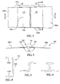
- FIG. 3 illustrates a top view of one specific structural member 104, in which first and second composite sections 104a, 104b respectively, are joined together at a splice joint 110 forming a "kink" or angle designated as "A".
- Each of the composite sections 104a-104c may comprise a cured composite laminate having any of various cross sectional geometries, however as will be described below, the composite sections 104a-104c chosen to illustrate the embodiments have a C-shape cross section as shown in FIG. 4 .
- the disclosed embodiments may be employed to form any of a wide variety of elongate, structural members by bonding composite sections together using composite splice joints 110.
- the disclosed embodiments may be used to splice composite sections, especially elongate sections to form composite floor beams, frames, stringers, to name only a few.
- the structural members may have any of a wide variety of cross sectional shapes, including, without limitation, a Z-shape shown in FIG, 5 , a T shape shown in FIG. 6 , a J shape shown in FIG. 7 , a hat shape shown in FIG. 8 or an I shape shown in FIG. 9 .
- first and second adjacent composite sections 104a, 104b may be bonded together using a composite splice member 112 which, as best shown in FIG. 4 , has a generally C-shape cross section corresponding to that of the composite sections 104a, 104b.
- the splice member 112 includes top and bottom flanges 112a, 112b connected by a web 112c.
- the splice member is shown as being of a one-piece construction in the illustrated example, the splice member 112 may comprise two or more sections or pieces in some applications. Since the composite sections 104a, 104b form a slight angle "A" ( FIG.
- the splice member 112 includes two adjacent sections 114 as shown in FIG. 2 which form an angle that is substantially equal to the angle "A". As best seen in FIG. 9 , the splice member 112 forms an overlapping, scarf type joint 110 with the adjoining composite sections 104a, 104b. It should be noted here however, that while a scarf joint has been illustrated, other types of joints may be employed to form the splice joint 112, including but not limited to lap joints, step lap joints, tabled splice joints, etc.
- the composite sections 104a, 104b each may comprise multiple laminated plies (not shown) of a fiber reinforced polymer resin, such as carbon fiber epoxy, in which the outer edges 117 include ply drop-offs (not shown) forming tapered or ramp geometry.
- the splice member 112 may be formed from multiple plies (not shown) of a fiber reinforced polymer resin which may be respectively aligned with the plies of the composite section 104a, 104b.
- the splice member 112 has a substantially V-shape cross section defining inclined or ramped surfaces 116 which overlap and are bonded to corresponding tapered edges 117 on the outer, adjoining ends of the composite sections 104a, 104b to form the splice joint 110.
- a splice joint 110 has been illustrated, other splice configurations may be possible, depending on the application.
- FIG. 11 broadly illustrates the steps of a method for structural bonding of the composite sections 104a-104c.
- the composite sections 104a-104c are laid up on a suitable tool (not shown) and are then individually cured at step 128, using heat and pressure, typically within an autoclave (not shown).
- a bonding machine 186 FIG. 1 is opened in preparation for receiving the ends of two adjacent composite sections, such as first and second composite sections 104a, 104b.
- the first and second composite sections 104a, 104b are loaded into bond assembly jigs 184 (BAJ) (see FIG. 1 ) and aligned with each other.
- the ends of the composite sections 104a, 104b are pulled into the bonding machine 186.
- the splice member 112 After the splice member 112 has been laid up and formed over a tool (not shown) at step 124, the splice member 112 is aligned and installed on the composite sections 104a, 104b at the splice joint 110, as shown at step 138.
- a vacuum bag is installed over the splice area which includes the splice member 112, following which, at 142, the bonding machine 186 may be closed.
- the green (uncured) splice member 112 is then bonded to the ends of the composite sections 104a, 104b by a series of steps shown at 144.
- a vacuum is drawn in the vacuum bag in order to partially consolidate the plies of the splice member 112 layup.
- a bag-like pressure bladder (discussed later) is pressurized which presses the splice member 112 and composite sections 104a, 104b against a mandrel 194 ( FIG. 13 ) thereby further consolidating the plies of the splice member 112 layup.
- a heating cycle is commenced at 150 in which the composite sections 104a, 104b and the splice member 112 are locally heated in order to cure the green splice member 112 and thereby bond it to the composite sections 104a, 104b to form a splice joint 110.
- the splice member 112 is cooled, following which the bonding machine 186 may be opened at 154.
- the vacuum bag is removed following which the splice member 112 is trimmed, as may be required, as shown at step 158.
- the resulting bonded splice joint 110 may be nondestructively inspected (NDI) at step 160, following which the structural member 104 may be removed from the bond assembly jigs 184. Depending upon the application, the completed structural member 104 may be painted and sealed at step 164. It should be noted here that steps 158-164 may be carried out in any desired order.
- the composite sections 104(a), 104(b) are cured before the uncured splice member 112 is applied to the splice joint 110.
- portions 115 of the composite sections 104(a), 104(b) spanning the splice member 112 may be in an uncured or partially cured ("staged") state at the time the splice member 212 is applied to the joint 110, while remaining areas of the composite sections 104(a), 104(b) are in a cured state.
- the uncured portions 115 of the composite sections 104(a), 104(b) may be cocured with the uncured splice member 112.
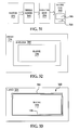
- FIG. 12 broadly illustrates components of a control system for the bonding machine 186.
- a controller 166 which may comprise a programmable logic controller (PLC) or a personal computer (PC), may use various software programs 178 to automatically carry out control functions in a preprogrammed manner. Operator controls and displays 180 allow operator access to the software programs 178 and form an interface with the controller 166 to allow adjustment of settings and display of process information.
- controller 166 may be coupled with the bond assembly jigs 184 ( FIG. 1 ) to sense or control the position of the long composite sections 104a, 104b relative to each other.
- the controller 166 may control various components and systems on the bonding machine 186, including heating/cooling systems 192, 196, bladder pressurization 174 and a bag vacuum 176.
- the bonding machine 186 may include a variety of later discussed sensors 182 that provide signals to the controller 166, such as temperatures and pressures.
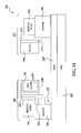
- FIG. 13 is a functional block diagram of the bonding machine 186, which broadly comprises a first, tool platform 188 and a second, pressure platform 190.
- Platforms 188, 190 may be mounted for sliding or rolling movement by guides 204 on a common base 202 for linear horizontal movement toward and away from each other. As will be discussed below, the platforms 188, 190 may be moved from an open position shown in FIG. 13 to a closed position ( FIGS. 16 and 21 ) in which heat and pressure are locally applied to the splice area comprising the splice member 112 and the ends of the assembled composite sections 104a, 104b while being supported by the bond assembly jigs 184.
- the platforms 188, 190 may be drawn and locked into their closed position using draw downs and locks 206.
- the tool platform 188 may include sensors 182, a heating/cooling system 192 and a mandrel 194.
- the pressure platform 190 may include sensors 182, a heating/cooling system 196, a pressure bladder 198 and pumps 200 used to draw a bag vacuum and pressurize the bladder 198.
- the bonding machine 186 broadly includes a tool tower 235 and a pressure tower 245 between which the assembled splice member 112 and composite sections 104a, 104b may be structurally bonded to form a bonded splice joint 110.
- the tool tower 235 includes a tool platform 188 mounted for linear horizontal movement on a base 202 by any suitable means.
- platform 188 includes feet 204 that are guided by tracks 220.
- a tool which may comprise a mandrel 194, is mounted on a mandrel base 215 which in turn is secured to a platen plate 214.
- the platen plate 214 is supported on the tool platform 188.
- the mandrel base 215 is releasable from the platen plate 214 by means of a series of locking levers 225 to allow the mandrel 194 to be easily removed and/or replaced.
- the pressure tower 245 includes a pressure platform 190 which also has feet 204 engaging the tracks 220.
- An inflatable pressure bladder 198 is held in a frame 199 that is secured to a shroud 224.
- the shroud 224 in turn, is secured to a platen plate 222 mounted on the pressure platform 190.
- Heating/cooling systems 192, 196 are respectively mounted on the traveling platforms 188, 190 for heating and cooling the mandrel 194, and the area surrounding the pressure bladder 198.
- Outer covers 226, 228 may be employed to protectively surround components on the tool and pressure towers 235, 245 respectively.
- An electric or other form of motor may be used to power the platforms 188, 190 to travel along the track 220 between an open, part-loading/unloading position as shown in FIGS. 13 and 14 , to a closed, part curing position as shown in FIG. 16 .
- a draw bar 221 ( FIG. 14 ) may be connected between the towers 235, 245 and employed to draw the platforms 188, 190 into a final closed position.
- Locking arms 218 may be used to lock the platforms 188, 190 together in their closed position.
- the pressure bladder 198 may have a cross section that is substantially a C-shape, similar to the shape of the mandrel 194.
- the bladder 198 may be formed of any suitable material capable of withstanding temperatures and pressures for the particular application, including for example and without limitation, silicone rubber.
- a fluid fitting 232 allows pressurized fluid, which may be a gas or a liquid to enter and exit the bladder 198.
- FIGS. 17 illustrate steps for readying and closing the bonding machine 186 in preparation for a bonding operation.
- the splice member 112 is first applied over the joint 110 between the composite sections 104a, 104b which are held in an engineering defined space by the previously discussed bond assembly jigs 184.
- a vacuum bag 234 may be applied over the splice member 112. Both the splice member 112 and the vacuum bag 234 extend the full thickness of the composite sections 104a, 104b which may include ply build-ups (not shown) on each side of the joint 110.
- the bonding machine 186 is closed by moving the platforms 188, 190 toward each other.
- a draw bar 221 FIG. 14
- locking arms 218 FIG. 15
- the composite sections 104a, 104b may experience movement along their longitudinal axes 265. In order to achieve final assembly requirements, this movement may be substantially reduced by holding the composite sections 104a, 104b using a pair of hold down plates 236 which span the splice joint 110 and clamp the adjacent ends of the composite sections 104a, 104b together.
- the hold down plates 236 may be fixed to abrasive, excess edge sections (not shown) on the top and bottom of the composite sections 104a, 104b overlying the splice joint 110 and rigidly connecting the composite sections 104a, 104b.
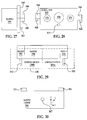
- FIG. 20 illustrates further details of the heating/cooling systems 192, 196 ( FIG. 14 ) that are used to heat the area of the splice joint 110 to a temperature sufficient to result in the curing of the slice member 112, and then cool the splice member 112 after curing.
- a heating element 216 heats a medium that is delivered through a supply duct 238 to a manifold 240 which routes the heated medium to distribution ducts 242.
- the distribution ducts 242 supply the heated medium to nozzles 244 which direct heated medium onto the inside surface of the mandrel 194 which is hollow on one side thereof.
- “medium” and “heated medium” are intended to include a variety of flowable mediums, including without limitation, air and other gases, as well as fluids, including oil. Other forms of heating such as without limitation, induction heating may also be possible.
- the heating element 230 heats a medium that is delivered through a supply duct 246 to a manifold 248 which routes the hot medium to distribution ducts 250.
- the distribution ducts 250 deliver the hot medium to nozzles 252 which direct the medium to the area surrounding the pressure the bladder 198 and the outside mold line (OML) of the splice member 112.
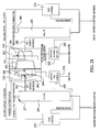
- FIG. 21 illustrates additional components of the heating/cooling systems 192, 196 as well as other systems such as a vacuum bag control 274 and bladder pressure control 282.
- An ambient medium is drawn through the heating element 216 and distributed by the manifold 240 to the nozzles 244 in order to heat the mandrel 194.
- the heating element 216 is controlled by a heat control 272, based in part on data received from a vacuum bag pressure sensor 295, a mandrel heater medium temperature sensor 277, a mandrel lag temperature sensor 262 and a mandrel control temperature 264.
- Vacuum within the vacuum bag 234 ( FIG. 18 ) is controlled by a vacuum bag control 274.
- an ambient medium is drawn through the heat element 230 to the hot medium manifold 248 which distributes the hot medium to the nozzles 244.
- Pressure applied to the pressure bladder 198 is controlled by a pressure control 282 which includes a pressure sensor 297 that provides pressure data to the heat control 276.
- the medium flowing through the heater 230 may further be controlled by the control 276 based on data generated by a pressure control temperature sensor 266 and a pressure heater temperature sensor 301.
- FIG. 22 illustrates an alternate embodiment of the tool tower 235.
- a self-contained, modular heating/cooling system 284 is supported by rails (not shown) on a traveling platform 288.
- the platform 288 is linearly displaceable on a portable base 290.
- the mandrel 194 is secured to a mandrel base 342 which is removably supported on a mandrel carrier 286.
- the mandrel carrier 286 is removably mounted on supports 357 positioned on the top of the platform 288.
- the heating/cooling system 284 includes later discussed medium supply and return ducts (not shown in FIG. 22 ) that are releasably coupled with the mandrel 194 by releasable connections 327.
- Blower drive motor 325 drives a blower 294 which moves the medium through a heating element 216, and then through a duct 296 to a pair of hot medium supply ducts 314, 316.
- the hot medium supply ducts 314, 316 are respectively coupled with inlet connections 326, 328 ( FIG. 25 ) passing through the back of the mandrel base 342.
- the hot medium supplied through inlet connections 326, 328 may be delivered to a nozzle plenum assembly 300 ( FIG. 24 ) that will be discussed later in more detail below.
- Medium returning from the nozzle plenum assembly 300 passes through a return medium inlet connection 330 and is delivered via a return duct 318 to a diverter valve 322.
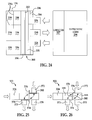
- FIG. 24 illustrates further details of the nozzle plenum assembly 300.
- the nozzle plenum assembly 300 is secured to the back of the mandrel 194.
- a plenum frame 334 to which box-shaped, perforated nozzles 338 are attached.
- the perforated nozzles 338 extend into compartments or zones 339 in the mandrel 194 that are defined by partial partition walls 194a.
- Each of the nozzles 338 is secured with fasteners (not shown) to the plenum frame 334.
- Medium inlet connections 326, 328 are secured to a plate 331 which is fixed to the plenum frame 334.
- the return medium connection 330 is mounted on a plate 336 that may include openings (nor shown) through which the connections 326, 328 extend.
- Incoming medium to inlet connections 326, 328 pass through the nozzles 338 which deliver the medium substantially evenly over the interior surface of the mandrel 94. Return medium passes through the connection 330 and 327 back to the diverter valve 322 ( FIG. 23 ).
- the diverter valve 322 includes a pair of hinged valve members 378, 380 respectively controlled by arms 374 and 376.
- a cool medium inlet 372 may be selectively opened to allow cool medium to flow into the valve 322.
- valve 380 is closed, and valve 378 is open to allow return medium received through the inlet 324 and to exit through the through the outlet 370 and thereby re-circulate during a heating cycle.
- the valve member 380 closes off the cool medium inlet 372 during the heating cycle.
- FIG. 26 illustrates the condition of the diverter valve 322 when cool medium is delivered to the mandrel 194 during a cooling cycle.
- Valve 378 is moved to a second closed position which diverts the return medium received through inlet 324 out through a medium vent 375.
- Valve member 380 has also been moved to its open position, allowing cool medium to enter through the inlet 372 and pass through the outlet 370 for delivery to the mandrel 194.
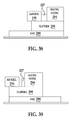
- FIGS. 26-30 better illustrate details of the mandrel 194 and mounting of the mandrel base 342 on the mandrel carrier 286.
- Pins 351 ( FIG. 30 ) on the mandrel carrier 286 are received within the sockets 348 ( FIGS. 27 and 28 ) secured to brackets 346 fixed to the mandrel base 342.
- a position limiting pin 363 on the back side of the mandrel base 342 provides a third contact point between the mandrel base 342 and the mandrel carrier 286.
- the positioning pin 363 engages a stop 367 ( FIG. 30 ) on the mandrel carrier 286.
- Ball joint connections formed between the sockets 348 and the pins 351 allow the mandrel 194 and the mandrel base 342 to expand along Y and Z axes shown in FIG. 30 , while the limiting pin 363 restrains such movement along the X axis.
- the mandrel base 342 is designed to minimize deflection and react the force of the pressure system through the mandrel 194.
- the mandrel 194 may include end brackets 352 each provided with a retaining pin 350.
- the retaining pins 350 are received within openings (not shown) in the composite sections 104a, 104b in order to maintain the composite sections 104a, 104b in aligned registration during the bonding process.
- the mandrel 194 is secured to the mandrel base 342 using fasteners (not shown).
- a sheet of insulation 358 along with spaced apart thermal barriers 364 are sandwiched between the mandrel 194 and the mandrel base 342 in order to insulate the mandrel 194 from the mandrel base 342.
- FIGS. 31 illustrates the use of insulation 366 surrounding the bladder 198 which functions to assist in retaining heat in the area of the splice joint 110 ( FIG. 10 ) during the curing process.
- heat required for curing of the splice member 112 ( FIG. 10 ) may be provided only from the tool side (tool tower 235 in FIG. 15 ) using the heating system 284 previously described in connection with FIG. 23 .
- a removable bladder assembly 382 includes an inflatable bladder 198.
- the edges of the bladder 198 may be secured to a semi-rigid frame 199 which may be formed of a semi-flexible material.
- the bladder frame 199 is releasably held in the bladder shroud 224 by a series of retainers 386 which hold the frame 199 in snap fit relationship, allowing the bladder assembly 382 to be easily removed and/or replaced.
- the bladder 198 may be a single bladder, or may comprise a redundant, double bladder of the type shown in FIGS. 33 and 34 .
- the bladder frame retainers 386 are secured to the bladder shroud 224 and may have a substantially circular cross section.
- the bladder frame 199 may be formed of a semi-rigid material such as reinforced silicone and may include a circular groove (not shown) along its periphery which receives the retainer 386 in a snap fit relationship.
- a second inflatable inner bladder 398 may be positioned inside the first, outer bladder 198 for redundancy in the event that the first bladder 198 develops a leak.
- FIG. 35 illustrate the use of the insulation 366 to retain the heat that is generated through the mandrel 194 where heating is provided only on the tool side of the bonding machine 186.
- FIG. 36 illustrates an alternate embodiment of a bladder frame 199 that may eliminate the need for use of the hold down plates 236 previously described in connection with FIG. 19 .
- a pressure bladder 198 is attached to a bladder frame 199 supported on the shroud 224 along with the insulation 366.
- Bladder 198 bears against a composite section 104a which is captured between the bladder 198 and the mandrel 194.
- the frame 199 has a rigid flange 355 which includes a portion 394 overlying and bearing against the composite section 104a.
- the flange 355 may assist in bagging and may apply sufficient force against the composite section 104a to hold down composite section 104a against movement, thereby eliminating the need for the hold down plates 236.
- FIG. 37 illustrates the use of a shroud cart 388 to position the shroud 224 relative to the mandrel 194.
- the shroud cart 388 is manually positioned in the work area. After being raised to a working height, it is moved toward the mandrel 194.
- the cart 388 includes a portable base 390 mounted on rollers (not shown) and a lifting mechanism 388 powered by an actuator piston 391.
- the lifting mechanism 388 may be used to lift the shroud 224 to the desired height, while the portable base 390 may be used to move the shroud 224 into the position shown in FIG. 37 in readiness for a bonding operation.
- the lifting mechanism 388 may be compliant to allow subtle adjustments to the shroud position without imparting load onto the composite sections 104a, 104b or the mandrel 194. Locating devices 392a, 392b on the shroud 224 and the platform 288 to assure that the shroud 224 and the mandrel 194 may be in aligned relationship to each other when the shroud has been moved into its closed position.
- FIGS. 38 and 39 illustrate the modular nature of the mandrel assembly and the heating system 284.
- the platform 288 is in a retracted position, and the mandrel 194 is coupled with the heating system 284.
- the platform 288 is moved to its forward position on the base 290 as shown in FIG. 39 .
- the heating system 284 maybe disconnected from the mandrel 194, using the releasable connections 327.
- Embodiments of the disclosure may find use in a variety of potential applications, particularly in the transportation industry, including for example, aerospace, marine and automotive applications.
- exemplary method 400 may include specification and design 404 of the aircraft 402 and material procurement 406.
- component and subassembly manufacturing 408 and system integration 410 of the aircraft 402 takes place.
- the aircraft 402 may go through certification and delivery 412 in order to be placed in service 414.
- routine maintenance and service 416 (which may also include modification, reconfiguration, refurbishment, and so on).
- a system integrator may include without limitation any number of aircraft manufacturers and major-system subcontractors; a third party may include without limitation any number of vendors, subcontractors, and suppliers; and an operator may be an airline, leasing company, military entity, service organization, and so on.
- the aircraft 402 produced by exemplary method 400 may include an airframe 418 with a plurality of systems 420 and an interior 422.
- high-level systems 420 include one or more of a propulsion system 424, an electrical system 426, a hydraulic system 428, and an environmental system 430. Any number of other systems may be included.
- an aerospace example is shown, the principles of the disclosure may be applied to other industries, such as the marine and automotive industries.
- Systems and methods embodied herein may be employed during any one or more of the stages of the production and service method 400.
- components or subassemblies corresponding to production process 408 may be fabricated or manufactured in a manner similar to components or subassemblies produced while the aircraft 402 is in service.
- one or more apparatus embodiments, method embodiments, or a combination thereof may be utilized during the production stages 408 and 410, for example, by substantially expediting assembly of or reducing the cost of an aircraft 402.
- apparatus embodiments, method embodiments, or a combination thereof may be utilized while the aircraft 402 is in service, for example and without limitation, to maintenance and service 416.
Landscapes
- Engineering & Computer Science (AREA)
- Mechanical Engineering (AREA)
- Physics & Mathematics (AREA)
- Thermal Sciences (AREA)
- Chemical & Material Sciences (AREA)
- Composite Materials (AREA)
- Architecture (AREA)
- Chemical Kinetics & Catalysis (AREA)
- General Chemical & Material Sciences (AREA)
- Structural Engineering (AREA)
- Civil Engineering (AREA)
- Electromagnetism (AREA)
- Aviation & Aerospace Engineering (AREA)
- Lining Or Joining Of Plastics Or The Like (AREA)
- Moulding By Coating Moulds (AREA)
- Joining Of Building Structures In Genera (AREA)
- Casting Or Compression Moulding Of Plastics Or The Like (AREA)
- Moulds For Moulding Plastics Or The Like (AREA)
- Heating, Cooling, Or Curing Plastics Or The Like In General (AREA)
Abstract
A composite structural member (104) includes first and second composite sections (104a,104b) spliced together by an overlapping composite splice member (112).
Description
- This disclosure generally relates to composite structures, and deals more particularly with a method and apparatus for joining composite sections together using bonded splices, as well as composite structural members made thereby.
- In order to produce relatively long composite structural members, composite sections are sometimes joined together using a splice joint. For example, in the aircraft industry, relatively long wing stringers, spars, frames, and other complex composite geometries may be formed by joining two or more long composite sections together using a metal splice member and fasteners. However, metal splice members may be undesirable for a number of assembly reasons.
- It may be possible to join composite structural member using composite splice members. However, it may not be practical to form composite splice joints between long composite sections because commercial autoclaves may not be large enough to accommodate the length of relatively long parts, such as wing stringers, spars, and frames.
- Accordingly, there is a need for a method and apparatus for joining structural members such as stringer, spar, and frame sections that allow the use of composite splice members. There is also a need for composite structural members formed from composite sections joined together by composite splice members.
- The disclosed embodiments provide a method and apparatus for structural bonding of relatively large composite structural members in a localized area that obviates the need for curing the bond in an autoclave. The ability to apply localized heat and pressure to the bond joint allows the use of a composite splice member and may eliminate the need for fasteners.
- According to one disclosed embodiment, a composite structural member comprises a first composite section and a second composite section. A composite splice member at least partially overlaps and splices together the first and second sections. The splice member forms a joint between the first and second composite sections having a V-shaped cross section. The composite sections may have complex geometries, including but not limited to a C shape, Z shape, J shape, T shape, an I shape and a hat shape cross section.
- According to a disclosed method embodiment, producing a composite structural member comprises forming a first and a second composite section. A composite splice member is formed and to form a splice joint between the first and second composite sections. The splice member is bonded to the first and second composite sections. Bonding the splice member may include using a press to locally apply heat and pressure to the joint. The bonding may be performed using an inflatable pressure bladder to apply pressure to the joint within a press while heat is being applied to the joint.
- According to another embodiment, apparatus for curing composite parts comprises a first platform and a second platform relatively moveable between an open, part loading position and a closed, part curing position; a tool against which a part may be pressed. The tool is supported by the first platform. At least a first bladder adapted to be pressurized and supported by the second platform for pressing the part against the tool. Means are provided for heating the tool. The first and second platforms may be independently portable.
- According to a further disclosed embodiment, apparatus is provided for joining composite sections of a composite structural member. The apparatus includes a bonding machine for bonding a composite splice member onto a joint between adjacent ends of two elongated, composite sections and, jigs on opposite sides of the bonding machine for supporting the composite sections in end-to-end relationship.
- According to a further method embodiment, joining two elongated composite sections comprises: supporting the composite sections in aligned, end-to-end relationship. Adjoining ends of the composite sections are placed within a press. A joint is formed between the composite sections by placing an uncured splice member over the adjoining ends of the composite sections. The press is closed and the splice member is bonded to the ends of the composite sections by using the press to apply heat and pressure to the joint.
- According to another embodiment, a heated tool assembly for forming a part comprises a first tool and a second tool between which a part may be formed. Means are provided for heating the first tool, including a heater for heating a medium, a blower for blowing the heated medium, a plurality of nozzles for directing the heated medium over the first tool, and a plenum coupled between the blower and the nozzles.
- In a first aspect of this invention, there is provided a composite structural member, comprising:
- a first composite section;
- a second composite section; and,
- a composite splice member at least partially overlapping and splicing together the first and second composite sections.
- Optionally, the first and second composite sections each have a cross section selected from the group consisting of:
- a C shape,
- a Z shape,
- a J shape,
- a T shape
- an I shape, and
- a hat shape.
- Optionally, the splice member includes a substantially V-shaped longitudinal section extending traverse to the cross section of the splice member.
- Optionally, the first and second composite sections extend in differing directions forming an angle, and
the composite splice member includes first and second portions respectively overlapping and joined to the first and second composite sections. - Optionally, the composite splice member forms a substantially V-shaped joint between the first and second composite sections.
- Optionally, the substantially V-shape joint includes:
- a first scarf joint between the composite splice member and the first composite section, and
- a second scarf joint between the composite splice member and the second composite section.
- Optionally, the first and second composite sections form one of a continuous spar, a continuous beam, a continuous stringer, or a continuous frame for an aircraft, and
the splice member is bonded to the first and second composite sections. - In a second aspect of this invention, there is provided an aircraft comprising an airframe including the composite structural member of the first aspect.
- In a third aspect of this invention, there is provided a method of manufacturing the airframe the second aspect, the method comprising assembling the composite structural member into a wing assembly, the wing assembly forming a component of the airframe.
- In a fourth aspect of this invention, there is provided a method of manufacturing the aircraft of the second aspect, comprising assembling the aircraft with at least one composite structural member according to the first aspect.
- Optionally, the first and second composite sections form a continuous part selected from the group consisting of -
- a spar,
- a beam,
- a stringer, and
- a frame.
- Optionally, the continuous part has a cross section selected from the group consisting of:
- a C shape,
- a Z shape,
- a J shape,
- a T shape,
- an I shape, and
- a hat shape.
- In a fifth aspect of the invention, there is provided a method of producing a composite structural member, comprising:
- forming a first composite section;
- forming a second composite section;
- forming a composite splice member; and,
- bonding the composite splice member to the first and second composite sections to form a splice joint between the first and second composite sections.
- Optionally, forming the first composite section includes forming a first layup of composite materials and curing the first layup,
- forming the second composite section includes forming a second layup of composite materials and curing the second layup,
- forming the composite splice member includes forming a third layup of composite materials, and
- bonding the splice member includes placing the third layup on the first and second composite sections and then curing the third layup.
- Optionally, bonding the splice member includes using a press to locally apply heat and pressure to the joint.
- Optionally, forming the first layup includes forming a first ramp along an edge of the first layup,
- forming the second layup includes forming a first second ramp along an edge of the second layup, and
- forming the third layup includes forming third and fourth ramps respectively overlapping the first and second ramps when the third layup has been placed on the first and second composite sections.
- Optionally, bonding the splice member includes:
- providing a mandrel,
- placing the joint over the mandrel,
- placing a vacuum bag over the joint, and
- using the bag to apply pressure to the joint.
- Optionally, bonding the splice member includes:
- using a pressurized bladder to apply pressure to the joint, and
- applying heat to the joint while pressure is being applied to the joint by the bladder.
- Optionally, using the bladder to apply pressure is performed within a press.
- In a sixth aspect of the invention, there is provided a composite structural member made by the method of the fifth aspect.
- Optionally, each of the first and second composite sections has a cross section selected from the group consisting of:
- a C shape,
- a Z shape,
- a J shape,
- a T shape,
- an I shape, and
- a hat shape.
- Optionally, the composite structural member is one selected from the group consisting of -
- a spar,
- a beam,
- a stringer, and
- a frame.
- In a seventh aspect of the invention, there is provided apparatus for curing composite parts, comprising:
- a first platform and a second platform relatively movable between an open position and a closed position;
- a tool against which a part may be pressed, the tool being supported by the first platform;
- at least a first bladder adapted to be pressurized and supported by the second platform for pressing the part against the tool; and,
- means for heating the tool.
- Optionally, each of the first and second platforms is portable.
- Optionally, the apparatus further comprises:
- first means for mounting the tool on the first platform for linear movement substantially horizontally toward and away from the part; and,
- second means for mounting the first bladder on the second platform for liner movement toward and away from the part.
- Optionally, the apparatus further comprises:
- a frame removably mounted on the second platform, and
- wherein the first bladder is attached to the frame and removable from the second platform along with the frame.
- Optionally, the heating means includes:
- a first heating system mounted on the first platform for heating the tool, and
- a second heating system mounted on the second platform for heating the part.
- Optionally, the first heating system includes:
- a heat source,
- a blower,
- ducting coupled with the blower and the heat source for carrying a heated medium, and
- nozzles coupled with the ducting for directing the heated medium onto the tool.
- Optionally, the means for heating the tool includes insulation surrounding the bladder.
- Optionally, the ducting includes a return medium duct for carrying heated medium away from the tool, and the first heating system further includes -
- a source of cool medium, and
- a valve coupled with the return medium duct and with the source of cool medium for selectively delivering cool medium to the tool to cool the part.
- Optionally, the medium is one of:
- air, and
- oil.
- In an eighth aspect of this invention, there is provided apparatus for splicing elongate composite sections of a composite structural member, comprising:
- a bonding machine for bonding a composite splice member onto a joint between adjacent ends of two composite sections; and
- jigs on opposite sides of the bonding machine for supporting the composite sections in end-to-end relationship.
- Optionally, the bonding machine includes a mandrel and alignment pins connecting the mandrel with the composite sections for maintaining the ends of the composite sections in a desired alignment within the bonding machine.
- Optionally, the jigs are arranged to support the composite sections along their lengths and maintain the composite sections in a desired alignment as the splice member is bonded onto the joint between the composite sections.
- Optionally, the bonding machine includes:
- means for applying heat to the joint for curing the splice member, and
- means for holding the composite sections against movement during curing.
- Optionally, the means for holding the composite sections includes a pair of plates spanning the joint and clamping the adjacent ends of the composite sections together.
- In a ninth aspect of the invention, there is provided a method of joining two elongate composite sections, comprising:
- supporting the composite sections in aligned, end-to-end relationship;
- placing adjoining ends of the composite sections within a press;
- forming a joint between the composite sections by placing an uncured splice member over the adjoining ends of the composite sections;
- closing the press; and,
- bonding the splice member to the ends of the composite sections by using the press to locally apply heat and pressure to the joint.
- Optionally, supporting the composite sections includes:
- positioning jigs on opposite sides of the press, and
- holding the composite sections in the jigs as the splice member is being bonded to the ends of the composite sections.
- Optionally, bonding the splice member includes:
- placing a vacuum bag over the splice member, and applying pressure to the splice member by evacuating the vacuum bag.
- Optionally, bonding the splice member includes:
- positioning a pressure bladder in the press over the splice member and the vacuum bag, and applying pressure to the splice member by pressurizing the bladder.
- Optionally, forming a joint includes placing the splice member and the ends of the composite sections on a mandrel, and applying heat to the joint includes directing a hot medium onto the mandrel.
- Optionally, applying heat to the joint includes:
- recirculating the medium directed over the mandrel, and heating the medium as it is re-circulated.
- Optionally, the composite sections form one of:
- a floor beam,
- a spar,
- a frame, and
- a stringer.
- In a tenth aspect of this invention, there is provided a heated tool assembly for forming a part, comprising:
- a first tool and a second tool between which a part may be formed; and,
- means for heating the first tool, including -
- a heater for heating a medium,
- a blower for blowing the heated medium,
- a plurality of nozzles for directing the heated medium over the first tool,
- a plenum coupled between the blower and the nozzles.
- Optionally, the plenum includes a manifold having a medium inlet and a plurality of medium outlets spatially arranged to direct medium to differing zones on the first tool.
- Optionally, each of the nozzles includes a perforated element through which heated medium may flow onto the first tool.
- Optionally, the first tool is a mandrel having a substantially hollow side, and
the nozzles extend into the hollow side of the mandrel. - Optionally, the second tool includes:
- a tool surface for forming the part and,
- thermal insulation for reducing the escape of heat through the tool surface.
- In an eleventh aspect of this invention, there is provided a method of joining composite sections to produce a continuous wing spar, comprising:
- forming a first cured composite spar section;
- forming a second cured composite spar section;
- holding the first and second spar sections in aligned, end-to-end relationship;
- placing an uncured composite splice member over a joint between the ends of the aligned spar sections;
- placing the ends of the aligned spar sections and the splice member in a press;
- applying a vacuum bag over the splice member;
- closing the press;
- applying a vacuum to the vacuum bag;
- applying pressure to the splice member using a pressure bladder to force the splice member against a tool;
- heating the tool and the splice member to cure the splice member;
- opening the press after the splice member has been cured; and,
- removing the continuous wing spar from the press.
- In a twelfth aspect of this invention, there is provided a method of joining composite sections to produce a continuous composite stringer, comprising:
- forming a first cured composite stringer section; forming a second cured composite stringer section;
- holding the first and second stringer sections in aligned, end-to-end relationship;
- placing an uncured composite splice member over a joint between the ends of the aligned stringer sections;
- placing the ends of the aligned stringer sections and the splice member in a press;
- applying a vacuum bag over the splice member;
- closing the press;
- applying a vacuum to the vacuum bag;
- applying pressure to the splice member using a pressure bladder to force the splice member against a tool;
- heating the tool and the splice member to cure the splice member;
- opening the press after the splice member has been cured; and,
- removing the continuous composite stringer from the press.
- In a thirteenth aspect of this invention, there is provided apparatus for splicing composite frame sections to form a continuous composite frame, comprising:
- a tool tower;
- a tool;
- means for removably mounting the tool on the tool tower;
- a modular heating and cooling system on the tool tower for heating and cooling the tool;
- a pressure tower;
- a pressure bladder on the pressure tower;
- means for pressurizing the pressure bladder to apply pressure to a splice joint between the ends of the frame sections;
- means for mounting the tool tower and the pressure tower for movement toward and away from each other;
- a locking system for locking the tool tower and the pressure tower together during a splicing operation; and,
- jigs for supporting the frame sections in aligned, end-to-end relationship and for holding the splice joint between the tool and the pressure bladder.
- The disclosed embodiments satisfy the need for a method and apparatus for forming a structural bond between two composite sections which eliminates the need for metal splice plates and does not require the bonded joint to be cured within an autoclave.
-
-
FIG. 1 is a broad block diagram of apparatus for joining composite sections to form a continuous structural member. -
FIG. 2 is an elevational view of the splice joint between two composite sections shown inFIG. 1 . -
FIG. 3 is a sectional view taken along the line 3-3 inFIG. 2 . -
FIG. 4 is a sectional view taken along the line 4-4 inFIG. 2 . -
FIGS. 5-9 are cross sectional views illustrating the shapes of other types of structural members. -
FIG. 10 is a sectional view in the area designated as "B" inFIG. 3 . -
FIG. 11 is a simplified flow diagram illustrating a method for structural bonding of composite sections. -
FIG. 12 is a block diagram illustrating a control system used in apparatus for structural bonding of composite sections. -
FIG. 13 is a functional block diagram of apparatus for structural bonding of composite sections. -
FIG. 14 is a block diagram of a bonding machine in an open position. -
FIG. 15 is a perspective view of the bonding machines shown inFIG. 14 . -
FIG. 16 is another block diagram of the bonding machine, shown in a closed position. -
FIG. 17 is a block diagram of a pressure bladder. -
FIG. 18 is a block diagram illustrating the installation of a vacuum bag and a splice member on the bonding machine. -
FIG. 19 is a block diagram showing a pair of hold down plates used to hold the composite sections during the curing process. -
FIG. 20 is a block and diagrammatic view illustrating heating systems used to heat the mandrel and bladder. -
FIG. 21 is a block diagram illustrating components of control systems forming part of the bonding machine. -
FIG. 22 is a diagrammatic illustration of an alternate form of the tool tower, and showing a modular heating/cooling system. -
FIG. 23 is a block diagram illustrating additional components of the modular heating and cooling system shown inFIG. 22 . -
FIG. 24 is a block diagram illustrating connections between a mandrel assembly and the modular heating and cooling system. -
FIG. 25 is a block diagram of a diverter valve forming part of the modular heating and cooling system, wherein the valve has been switched to a heating mode. -
FIG. 26 is a block diagram similar toFIG. 25 , but showing the valve having been switched to a cooling mode. -
FIG. 27 is a block diagram illustrating components of the mandrel assembly. -
FIG. 28 is another block diagram illustrating additional components of the mandrel assembly. -
FIG. 29 is a block diagram illustrating details of the mandrel useful in indexing the spar sections. -
FIG. 30 is a block diagram of the mandrel carrier. -
FIG. 31 is a block diagram illustrating the relationship between components of the mandrel assembly and mandrel base. -
FIG. 32 is a block diagram of a bladder and shroud assembly. -
FIG. 33 is a block diagram showing a removable bladder and frame. -
FIG. 34 is a block diagram of a dual pressure bladder. -
FIG. 35 is a block diagram illustrating the pressure bladder for applying pressure to composite sections. -
FIG. 36 is a block diagram illustrating an alternate form of a frame useful in holding composite sections in place during cure. -
FIG. 37 is a block diagram illustrating a portable pressure shroud cart in relation to the tool platform. -
FIG. 38 is a block diagram illustrating the tool platform in a retracted position. -
FIG. 39 is a view similar toFIG. 38 but showing the tool platform having been moved to a forward position and the mandrel assembly having been disconnected from the heating/cooling system in preparation for removal of the mandrel carrier. -
FIG. 40 is a flow diagram of aircraft production and service methodology. -
FIG. 41 is a block diagram of an aircraft. -
FIG. 1 illustrates atypical production cell 208 that may be used to join elongate composite sections, such ascomposite sections structural member 104, such as without limitation, a stringer, a spar, or a frame. At least a first composite section 104(a) and a second composite section 104(b) are joined in end-to-end relationship using a structural bond that form a splice joint 110. The composite sections 104-104c may be supported by a plurality of aligned bond assembly jigs 184. The bond assembly jigs 184 support thecomposite sections 104a-104c in aligned relationship while allowing the latter to be pulled along theirlongitudinal axes 265 intobonding machines 186 respectively located atbonding stations bonding stations structural member 104 where the splice joints 110 are to be bonded. - Referring to
FIGS. 2-4 , in accordance with the disclosed embodiments, thestructural member 104 may be formed by joining a number of composite sections such ascomposite sections FIG. 3 illustrates a top view of one specificstructural member 104, in which first and secondcomposite sections composite sections 104a-104c may comprise a cured composite laminate having any of various cross sectional geometries, however as will be described below, thecomposite sections 104a-104c chosen to illustrate the embodiments have a C-shape cross section as shown inFIG. 4 . - It should be noted here that while a particular
structural member 104 has been illustrated in the Figures, the disclosed embodiments may be employed to form any of a wide variety of elongate, structural members by bonding composite sections together using composite splice joints 110. For example, and without limitation, the disclosed embodiments may be used to splice composite sections, especially elongate sections to form composite floor beams, frames, stringers, to name only a few. Moreover, the structural members may have any of a wide variety of cross sectional shapes, including, without limitation, a Z-shape shown inFIG, 5 , a T shape shown inFIG. 6 , a J shape shown inFIG. 7 , a hat shape shown inFIG. 8 or an I shape shown inFIG. 9 . - Referring now to
FIGS. 2 and 3 , first and second adjacentcomposite sections composite splice member 112 which, as best shown inFIG. 4 , has a generally C-shape cross section corresponding to that of thecomposite sections splice member 112 includes top andbottom flanges web 112c. Although the splice member is shown as being of a one-piece construction in the illustrated example, thesplice member 112 may comprise two or more sections or pieces in some applications. Since thecomposite sections FIG. 3 ), thesplice member 112 includes twoadjacent sections 114 as shown inFIG. 2 which form an angle that is substantially equal to the angle "A". As best seen inFIG. 9 , thesplice member 112 forms an overlapping, scarf type joint 110 with the adjoiningcomposite sections - Referring now to
FIG. 10 , thecomposite sections outer edges 117 include ply drop-offs (not shown) forming tapered or ramp geometry. Similarly, thesplice member 112 may be formed from multiple plies (not shown) of a fiber reinforced polymer resin which may be respectively aligned with the plies of thecomposite section splice member 112 has a substantially V-shape cross section defining inclined or rampedsurfaces 116 which overlap and are bonded to corresponding taperededges 117 on the outer, adjoining ends of thecomposite sections - Attention is now directed to
FIG. 11 which broadly illustrates the steps of a method for structural bonding of thecomposite sections 104a-104c. Beginning atstep 126, thecomposite sections 104a-104c are laid up on a suitable tool (not shown) and are then individually cured atstep 128, using heat and pressure, typically within an autoclave (not shown). Next, at 130, a bonding machine 186 (FIG. 1 ) is opened in preparation for receiving the ends of two adjacent composite sections, such as first and secondcomposite sections - At 132, the first and second
composite sections FIG. 1 ) and aligned with each other. Next, at 134, the ends of thecomposite sections bonding machine 186. After thesplice member 112 has been laid up and formed over a tool (not shown) atstep 124, thesplice member 112 is aligned and installed on thecomposite sections step 138. - At 140, a vacuum bag is installed over the splice area which includes the
splice member 112, following which, at 142, thebonding machine 186 may be closed. The green (uncured)splice member 112 is then bonded to the ends of thecomposite sections splice member 112 layup. Next, at 148, a bag-like pressure bladder (discussed later) is pressurized which presses thesplice member 112 andcomposite sections FIG. 13 ) thereby further consolidating the plies of thesplice member 112 layup. - At this point, a heating cycle is commenced at 150 in which the
composite sections splice member 112 are locally heated in order to cure thegreen splice member 112 and thereby bond it to thecomposite sections splice member 112 is cooled, following which thebonding machine 186 may be opened at 154. At 156, the vacuum bag is removed following which thesplice member 112 is trimmed, as may be required, as shown atstep 158. The resulting bonded splice joint 110 may be nondestructively inspected (NDI) atstep 160, following which thestructural member 104 may be removed from the bond assembly jigs 184. Depending upon the application, the completedstructural member 104 may be painted and sealed atstep 164. It should be noted here that steps 158-164 may be carried out in any desired order. - In the method embodiment described above in connection with
FIG. 11 , the composite sections 104(a), 104(b) are cured before theuncured splice member 112 is applied to the splice joint 110. In other embodiments however, it is possible that only portions of the composite sections 104(a), 104(b) are cured before theuncured splice member 112 is applied to the splice joint 110. For example, as shown inFIG. 2 ,portions 115 of the composite sections 104(a), 104(b) spanning thesplice member 112 may be in an uncured or partially cured ("staged") state at the time thesplice member 212 is applied to the joint 110, while remaining areas of the composite sections 104(a), 104(b) are in a cured state. In this alternative embodiment, theuncured portions 115 of the composite sections 104(a), 104(b) may be cocured with theuncured splice member 112. -
FIG. 12 broadly illustrates components of a control system for thebonding machine 186. Acontroller 166, which may comprise a programmable logic controller (PLC) or a personal computer (PC), may usevarious software programs 178 to automatically carry out control functions in a preprogrammed manner. Operator controls and displays 180 allow operator access to thesoftware programs 178 and form an interface with thecontroller 166 to allow adjustment of settings and display of process information. In some cases,controller 166 may be coupled with the bond assembly jigs 184 (FIG. 1 ) to sense or control the position of thelong composite sections - The
controller 166 may control various components and systems on thebonding machine 186, including heating/cooling systems bladder pressurization 174 and abag vacuum 176. Thebonding machine 186 may include a variety of later discussedsensors 182 that provide signals to thecontroller 166, such as temperatures and pressures. -
FIG. 13 is a functional block diagram of thebonding machine 186, which broadly comprises a first,tool platform 188 and a second,pressure platform 190.Platforms guides 204 on acommon base 202 for linear horizontal movement toward and away from each other. As will be discussed below, theplatforms FIG. 13 to a closed position (FIGS. 16 and21 ) in which heat and pressure are locally applied to the splice area comprising thesplice member 112 and the ends of the assembledcomposite sections splice member 112 to thecomposite sections platforms tool platform 188 may includesensors 182, a heating/cooling system 192 and amandrel 194. Similarly, thepressure platform 190 may includesensors 182, a heating/cooling system 196, apressure bladder 198 and pumps 200 used to draw a bag vacuum and pressurize thebladder 198. - Attention is now directed to
FIGS. 13-15 which illustrate further details of thebonding machine 186. Thebonding machine 186 broadly includes atool tower 235 and apressure tower 245 between which the assembledsplice member 112 andcomposite sections tool tower 235 includes atool platform 188 mounted for linear horizontal movement on abase 202 by any suitable means. In the illustrated example,platform 188 includesfeet 204 that are guided bytracks 220. A tool, which may comprise amandrel 194, is mounted on amandrel base 215 which in turn is secured to aplaten plate 214. Theplaten plate 214 is supported on thetool platform 188. Themandrel base 215 is releasable from theplaten plate 214 by means of a series of lockinglevers 225 to allow themandrel 194 to be easily removed and/or replaced. - The
pressure tower 245 includes apressure platform 190 which also hasfeet 204 engaging thetracks 220. Aninflatable pressure bladder 198 is held in aframe 199 that is secured to ashroud 224. Theshroud 224 in turn, is secured to aplaten plate 222 mounted on thepressure platform 190. Heating/cooling systems platforms mandrel 194, and the area surrounding thepressure bladder 198. Outer covers 226, 228 may be employed to protectively surround components on the tool and pressure towers 235, 245 respectively. An electric or other form of motor (not shown) may be used to power theplatforms track 220 between an open, part-loading/unloading position as shown inFIGS. 13 and14 , to a closed, part curing position as shown inFIG. 16 . A draw bar 221 (FIG. 14 ) may be connected between thetowers platforms arms 218 may be used to lock theplatforms - Referring particularly to
FIG. 17 , thepressure bladder 198 may have a cross section that is substantially a C-shape, similar to the shape of themandrel 194. Thebladder 198 may be formed of any suitable material capable of withstanding temperatures and pressures for the particular application, including for example and without limitation, silicone rubber. Afluid fitting 232 allows pressurized fluid, which may be a gas or a liquid to enter and exit thebladder 198. - Attention is now directed to
FIGS. 17 which illustrate steps for readying and closing thebonding machine 186 in preparation for a bonding operation. Thesplice member 112 is first applied over the joint 110 between thecomposite sections bonding machine 186 still open, avacuum bag 234 may be applied over thesplice member 112. Both thesplice member 112 and thevacuum bag 234 extend the full thickness of thecomposite sections splice member 112 andvacuum bag 234 having been installed, thebonding machine 186 is closed by moving theplatforms FIG. 14 ) may be employed if necessary to pull theplatforms FIG. 15 ) can be rotated to lock the position of themandrel 194 relative to thepressure bladder shroud 224. - Referring now to
FIG. 19 , during the curing process in which thecomposite sections composite sections longitudinal axes 265. In order to achieve final assembly requirements, this movement may be substantially reduced by holding thecomposite sections plates 236 which span the splice joint 110 and clamp the adjacent ends of thecomposite sections plates 236 may be fixed to abrasive, excess edge sections (not shown) on the top and bottom of thecomposite sections composite sections - Attention is now directed to
FIG. 20 which illustrates further details of the heating/cooling systems 192, 196 (FIG. 14 ) that are used to heat the area of the splice joint 110 to a temperature sufficient to result in the curing of theslice member 112, and then cool thesplice member 112 after curing. On the side of thetool tower 235, aheating element 216 heats a medium that is delivered through asupply duct 238 to a manifold 240 which routes the heated medium todistribution ducts 242. Thedistribution ducts 242 supply the heated medium tonozzles 244 which direct heated medium onto the inside surface of themandrel 194 which is hollow on one side thereof. As used herein, "medium" and "heated medium" are intended to include a variety of flowable mediums, including without limitation, air and other gases, as well as fluids, including oil. Other forms of heating such as without limitation, induction heating may also be possible. - On the side of the
pressure tower 245, theheating element 230 heats a medium that is delivered through asupply duct 246 to a manifold 248 which routes the hot medium todistribution ducts 250. Thedistribution ducts 250 deliver the hot medium tonozzles 252 which direct the medium to the area surrounding the pressure thebladder 198 and the outside mold line (OML) of thesplice member 112. -
FIG. 21 illustrates additional components of the heating/cooling systems vacuum bag control 274 andbladder pressure control 282. An ambient medium is drawn through theheating element 216 and distributed by the manifold 240 to thenozzles 244 in order to heat themandrel 194. Theheating element 216 is controlled by aheat control 272, based in part on data received from a vacuumbag pressure sensor 295, a mandrel heatermedium temperature sensor 277, a mandrellag temperature sensor 262 and amandrel control temperature 264. Vacuum within the vacuum bag 234 (FIG. 18 ) is controlled by avacuum bag control 274. - On the side of the
pressure tower 245, an ambient medium is drawn through theheat element 230 to the hotmedium manifold 248 which distributes the hot medium to thenozzles 244. Pressure applied to thepressure bladder 198 is controlled by apressure control 282 which includes apressure sensor 297 that provides pressure data to theheat control 276. The medium flowing through theheater 230 may further be controlled by thecontrol 276 based on data generated by a pressurecontrol temperature sensor 266 and a pressureheater temperature sensor 301. - Attention is now directed to
FIG. 22 which illustrates an alternate embodiment of thetool tower 235. In this example, a self-contained, modular heating/cooling system 284 is supported by rails (not shown) on a travelingplatform 288. Theplatform 288 is linearly displaceable on aportable base 290. Themandrel 194 is secured to amandrel base 342 which is removably supported on amandrel carrier 286. Themandrel carrier 286 is removably mounted onsupports 357 positioned on the top of theplatform 288. Thus, themandrel carrier 286 may be easily removed from theplatform 288, and themandrel 194 along with themandrel base 342 may be removed from themandrel carrier 286. The heating/cooling system 284 includes later discussed medium supply and return ducts (not shown inFIG. 22 ) that are releasably coupled with themandrel 194 byreleasable connections 327. - Additional details of the heating/
cooling system 284 are shown inFIGS. 22-25 . Blower drivemotor 325 drives ablower 294 which moves the medium through aheating element 216, and then through aduct 296 to a pair of hotmedium supply ducts 314, 316. The hotmedium supply ducts 314, 316 are respectively coupled withinlet connections 326, 328 (FIG. 25 ) passing through the back of themandrel base 342. The hot medium supplied throughinlet connections FIG. 24 ) that will be discussed later in more detail below. Medium returning from thenozzle plenum assembly 300 passes through a returnmedium inlet connection 330 and is delivered via areturn duct 318 to adiverter valve 322. -
FIG. 24 illustrates further details of thenozzle plenum assembly 300. Thenozzle plenum assembly 300 is secured to the back of themandrel 194. Aplenum frame 334 to which box-shaped,perforated nozzles 338 are attached. Theperforated nozzles 338 extend into compartments orzones 339 in themandrel 194 that are defined bypartial partition walls 194a. Each of thenozzles 338 is secured with fasteners (not shown) to theplenum frame 334.Medium inlet connections plate 331 which is fixed to theplenum frame 334. Thereturn medium connection 330 is mounted on aplate 336 that may include openings (nor shown) through which theconnections inlet connections nozzles 338 which deliver the medium substantially evenly over the interior surface of the mandrel 94. Return medium passes through theconnection FIG. 23 ). - Referring to
FIGS. 25-26 , thediverter valve 322 includes a pair of hingedvalve members arms cool medium inlet 372 may be selectively opened to allow cool medium to flow into thevalve 322. In the condition shown inFIG. 26 ,valve 380 is closed, andvalve 378 is open to allow return medium received through theinlet 324 and to exit through the through theoutlet 370 and thereby re-circulate during a heating cycle. Thevalve member 380 closes off the coolmedium inlet 372 during the heating cycle. -
FIG. 26 illustrates the condition of thediverter valve 322 when cool medium is delivered to themandrel 194 during a cooling cycle.Valve 378 is moved to a second closed position which diverts the return medium received throughinlet 324 out through amedium vent 375.Valve member 380 has also been moved to its open position, allowing cool medium to enter through theinlet 372 and pass through theoutlet 370 for delivery to themandrel 194. - Attention is now directed to
FIGS. 26-30 which better illustrate details of themandrel 194 and mounting of themandrel base 342 on themandrel carrier 286. Pins 351 (FIG. 30 ) on themandrel carrier 286 are received within the sockets 348 (FIGS. 27 and 28 ) secured tobrackets 346 fixed to themandrel base 342. Aposition limiting pin 363 on the back side of themandrel base 342 provides a third contact point between themandrel base 342 and themandrel carrier 286. Thepositioning pin 363 engages a stop 367 (FIG. 30 ) on themandrel carrier 286. Ball joint connections formed between thesockets 348 and thepins 351 allow themandrel 194 and themandrel base 342 to expand along Y and Z axes shown inFIG. 30 , while the limitingpin 363 restrains such movement along the X axis. Themandrel base 342 is designed to minimize deflection and react the force of the pressure system through themandrel 194. As shown inFIG. 29 , themandrel 194 may includeend brackets 352 each provided with a retainingpin 350. The retaining pins 350 are received within openings (not shown) in thecomposite sections composite sections - Referring to
FIG. 31 , themandrel 194 is secured to themandrel base 342 using fasteners (not shown). A sheet ofinsulation 358 along with spaced apartthermal barriers 364 are sandwiched between themandrel 194 and themandrel base 342 in order to insulate themandrel 194 from themandrel base 342. -
FIGS. 31 illustrates the use ofinsulation 366 surrounding thebladder 198 which functions to assist in retaining heat in the area of the splice joint 110 (FIG. 10 ) during the curing process. In this embodiment, heat required for curing of the splice member 112 (FIG. 10 ) may be provided only from the tool side (tool tower 235 inFIG. 15 ) using theheating system 284 previously described in connection withFIG. 23 . In some applications, it may be necessary or desirable to place an optional heater element (not shown) between thebladder 198 and the surroundinginsulation 366. - Referring now to
FIG. 33 , aremovable bladder assembly 382 includes aninflatable bladder 198. The edges of thebladder 198 may be secured to asemi-rigid frame 199 which may be formed of a semi-flexible material. Thebladder frame 199 is releasably held in thebladder shroud 224 by a series ofretainers 386 which hold theframe 199 in snap fit relationship, allowing thebladder assembly 382 to be easily removed and/or replaced. - The
bladder 198 may be a single bladder, or may comprise a redundant, double bladder of the type shown inFIGS. 33 and34 . Thebladder frame retainers 386 are secured to thebladder shroud 224 and may have a substantially circular cross section. Thebladder frame 199 may be formed of a semi-rigid material such as reinforced silicone and may include a circular groove (not shown) along its periphery which receives theretainer 386 in a snap fit relationship. A second inflatableinner bladder 398 may be positioned inside the first,outer bladder 198 for redundancy in the event that thefirst bladder 198 develops a leak.FIG. 35 illustrate the use of theinsulation 366 to retain the heat that is generated through themandrel 194 where heating is provided only on the tool side of thebonding machine 186. - Attention is now directed to
FIG. 36 which illustrates an alternate embodiment of abladder frame 199 that may eliminate the need for use of the hold downplates 236 previously described in connection withFIG. 19 . Apressure bladder 198 is attached to abladder frame 199 supported on theshroud 224 along with theinsulation 366.Bladder 198 bears against acomposite section 104a which is captured between thebladder 198 and themandrel 194. Theframe 199 has arigid flange 355 which includes aportion 394 overlying and bearing against thecomposite section 104a. Theflange 355 may assist in bagging and may apply sufficient force against thecomposite section 104a to hold downcomposite section 104a against movement, thereby eliminating the need for the hold downplates 236. - Attention is now directed to
FIG. 37 which illustrates the use of ashroud cart 388 to position theshroud 224 relative to themandrel 194. Theshroud cart 388 is manually positioned in the work area. After being raised to a working height, it is moved toward themandrel 194. Thecart 388 includes aportable base 390 mounted on rollers (not shown) and alifting mechanism 388 powered by anactuator piston 391. Thelifting mechanism 388 may be used to lift theshroud 224 to the desired height, while theportable base 390 may be used to move theshroud 224 into the position shown inFIG. 37 in readiness for a bonding operation. Thelifting mechanism 388 may be compliant to allow subtle adjustments to the shroud position without imparting load onto thecomposite sections mandrel 194. Locatingdevices shroud 224 and theplatform 288 to assure that theshroud 224 and themandrel 194 may be in aligned relationship to each other when the shroud has been moved into its closed position. -
FIGS. 38 and 39 illustrate the modular nature of the mandrel assembly and theheating system 284. As shown inFIG. 38 , theplatform 288 is in a retracted position, and themandrel 194 is coupled with theheating system 284. In order to remove and/or replace themandrel 194, theplatform 288 is moved to its forward position on the base 290 as shown inFIG. 39 . Then, theheating system 284 maybe disconnected from themandrel 194, using thereleasable connections 327. - Embodiments of the disclosure may find use in a variety of potential applications, particularly in the transportation industry, including for example, aerospace, marine and automotive applications. Thus, referring now to
FIGS. 40 and 41 , embodiments of the disclosure may be used in the context of an aircraft manufacturing andservice method 400 as shown inFigure 40 and anaircraft 402 as shown inFigure 41 . During pre-production,exemplary method 400 may include specification anddesign 404 of theaircraft 402 andmaterial procurement 406. During production, component andsubassembly manufacturing 408 andsystem integration 410 of theaircraft 402 takes place. Thereafter, theaircraft 402 may go through certification anddelivery 412 in order to be placed inservice 414. While in service by a customer, theaircraft 212 is scheduled for routine maintenance and service 416 (which may also include modification, reconfiguration, refurbishment, and so on). - Each of the processes of
method 400 may be performed or carried out by a system integrator, a third party, and/or an operator (e.g., a customer). For the purposes of this description, a system integrator may include without limitation any number of aircraft manufacturers and major-system subcontractors; a third party may include without limitation any number of vendors, subcontractors, and suppliers; and an operator may be an airline, leasing company, military entity, service organization, and so on. - As shown in
FIG. 41 , theaircraft 402 produced byexemplary method 400 may include anairframe 418 with a plurality ofsystems 420 and an interior 422. Examples of high-level systems 420 include one or more of apropulsion system 424, anelectrical system 426, ahydraulic system 428, and anenvironmental system 430. Any number of other systems may be included. Although an aerospace example is shown, the principles of the disclosure may be applied to other industries, such as the marine and automotive industries. - Systems and methods embodied herein may be employed during any one or more of the stages of the production and
service method 400. For example, components or subassemblies corresponding toproduction process 408 may be fabricated or manufactured in a manner similar to components or subassemblies produced while theaircraft 402 is in service. Also, one or more apparatus embodiments, method embodiments, or a combination thereof may be utilized during the production stages 408 and 410, for example, by substantially expediting assembly of or reducing the cost of anaircraft 402. Similarly, one or more of apparatus embodiments, method embodiments, or a combination thereof may be utilized while theaircraft 402 is in service, for example and without limitation, to maintenance andservice 416. - Although the embodiments of this disclosure have been described with respect to certain exemplary embodiments, it is to be understood that the specific embodiments are for purposes of illustration and not limitation, as other variations will occur to those of skill in the art.
Claims (14)
- A composite structural member, comprising:a first composite section;a second composite section; and,a composite splice member at least partially overlapping and splicing together the first and second composite sections.
- The composite structure of claim 1, wherein the first and second composite sections each have a cross section selected from the group consisting of:a C shape,a Z shape,a J shape,a T shapean I shape, anda hat shape.
- The composite structure of claim 2, wherein the splice member includes a substantially V-shaped longitudinal section extending traverse to the cross section of the splice member.
- The composite structure of claim 1, wherein:the first and second composite sections extend in differing directions forming an angle, andthe composite splice member includes first and second portions respectively overlapping and joined to the first and second composite sections.
- The composite structure of claim 1, wherein the composite splice member forms a substantially V-shaped joint between the first and second composite sections.
- The composite structure of claim 5, wherein the substantially V-shape joint includes:a first scarf joint between the composite splice member and the first composite section, anda second scarf joint between the composite splice member and the second composite section.
- The composite structure of claim 1, wherein:the first and second composite sections form one of a continuous spar, a continuous beam, a continuous stringer, or a continuous frame for an aircraft, andthe splice member is bonded to the first and second composite sections.
- A method of producing a composite structural member, comprising:forming a first composite section;forming a second composite section;forming a composite splice member; and,bonding the composite splice member to the first and second composite sections to form a splice joint between the first and second composite sections.
- The method of claim 8, wherein:forming the first composite section includes forming a first layup of composite materials and curing the first layup,forming the second composite section includes forming a second layup of composite materials and curing the second layup,forming the composite splice member includes forming a third layup of composite materials, andbonding the splice member includes placing the third layup on the first and second composite sections and then curing the third layup.
- The method of claim 8, wherein bonding the splice member includes using a press to locally apply heat and pressure to the joint.
- The method of claim 9, wherein:forming the first layup includes forming a first ramp along an edge of the first layup,forming the second layup includes forming a first second ramp along an edge of the second layup, andforming the third layup includes forming third and fourth ramps respectively overlapping the first and second ramps when the third layup has been placed on the first and second composite sections.
- The method of claim 8, wherein bonding the splice member includes:providing a mandrel,placing the joint over the mandrel,placing a vacuum bag over the joint, andusing the bag to apply pressure to the joint.
- The method of claim 8 wherein bonding the splice member includes:using a pressurized bladder to apply pressure to the joint, andapplying heat to the joint while pressure is being applied to the joint by the bladder.
- The method of claim 18, wherein using the bladder to apply pressure is performed within a press.
Priority Applications (1)
| Application Number | Priority Date | Filing Date | Title |
|---|---|---|---|
| EP11169616.7A EP2404740B1 (en) | 2008-11-13 | 2009-11-13 | Method and apparatus for joining composite structural members |
Applications Claiming Priority (1)
| Application Number | Priority Date | Filing Date | Title |
|---|---|---|---|
| US12/270,682 US20100116938A1 (en) | 2008-11-13 | 2008-11-13 | Method and apparatus for joining composite structural members and structural members made thereby |
Related Child Applications (1)
| Application Number | Title | Priority Date | Filing Date |
|---|---|---|---|
| EP11169616.7A Division EP2404740B1 (en) | 2008-11-13 | 2009-11-13 | Method and apparatus for joining composite structural members |
Publications (1)
| Publication Number | Publication Date |
|---|---|
| EP2186622A1 true EP2186622A1 (en) | 2010-05-19 |
Family
ID=41508967
Family Applications (2)
| Application Number | Title | Priority Date | Filing Date |
|---|---|---|---|
| EP09176006A Withdrawn EP2186622A1 (en) | 2008-11-13 | 2009-11-13 | Method for joining composite structural members and structural members made thereby |
| EP11169616.7A Active EP2404740B1 (en) | 2008-11-13 | 2009-11-13 | Method and apparatus for joining composite structural members |
Family Applications After (1)
| Application Number | Title | Priority Date | Filing Date |
|---|---|---|---|
| EP11169616.7A Active EP2404740B1 (en) | 2008-11-13 | 2009-11-13 | Method and apparatus for joining composite structural members |
Country Status (7)
| Country | Link |
|---|---|
| US (1) | US20100116938A1 (en) |
| EP (2) | EP2186622A1 (en) |
| JP (1) | JP5616050B2 (en) |
| KR (1) | KR20100054104A (en) |
| CN (1) | CN101761769A (en) |
| ES (1) | ES2611527T3 (en) |
| PT (1) | PT2404740T (en) |
Cited By (30)
| Publication number | Priority date | Publication date | Assignee | Title |
|---|---|---|---|---|
| WO2012004571A2 (en) | 2010-07-08 | 2012-01-12 | Blade Dynamics Limited | A wind turbine blade |
| FR2975043A1 (en) * | 2011-05-11 | 2012-11-16 | Versaplast | COMPOSITE PANEL AND METHOD FOR PRODUCING THE SAME |
| EP3098063A1 (en) * | 2015-05-28 | 2016-11-30 | Blade Dynamics Limited | A method and tool for forming a scarf joint |
| US9651029B2 (en) | 2012-08-23 | 2017-05-16 | Blade Dynamics Limited | Wind turbine tower |
| US9669579B2 (en) | 2008-11-13 | 2017-06-06 | The Boeing Company | Aircraft skin attachment system |
| US9863258B2 (en) | 2012-09-26 | 2018-01-09 | Blade Dynamics Limited | Method of forming a structural connection between a spar cap and a fairing for a wind turbine blade |
| EP3155258B1 (en) | 2014-06-11 | 2020-01-15 | LM WP Patent Holding A/S | A tip system for a wind turbine blade |
| US10830207B2 (en) | 2018-08-28 | 2020-11-10 | General Electric Company | Spar configuration for jointed wind turbine rotor blades |
| EP4001101A1 (en) | 2020-11-18 | 2022-05-25 | The Boeing Company | Fabrication of multi-segment spars |
| NL2027428B1 (en) * | 2021-01-26 | 2022-08-26 | Boeing Co | Fabrication of multi-segment spars |
| US11486352B2 (en) | 2018-11-01 | 2022-11-01 | General Electric Company | Scarf connection for a wind turbine rotor blade |
| US11536246B2 (en) | 2018-11-01 | 2022-12-27 | General Electric Company | Span-wise extending pin for joining rotor blade segments |
| US11542917B2 (en) | 2018-12-11 | 2023-01-03 | General Electric Company | Beam structure for a segmented rotor blade having a transitioning shape |
| US11572863B2 (en) | 2018-10-25 | 2023-02-07 | General Electric Company | Spar cap configuration for a jointed wind turbine blade |
| US11614069B2 (en) | 2018-12-13 | 2023-03-28 | General Electric Company | Jointed rotor blade having a chord-wise extending pin supported via one or more structural members |
| US11668277B2 (en) | 2018-11-01 | 2023-06-06 | General Electric Company | Wind turbine jointed rotor blade having a hollow chord-wise extending pin |
| US11680555B2 (en) | 2018-10-31 | 2023-06-20 | General Electric Company | Jointed wind turbine rotor blade having varying material combinations along its span for pin reinforcement |
| US11767819B2 (en) | 2018-11-01 | 2023-09-26 | General Electric Company | Spacer material, for reducing a bond gap between a beam structure and a blade shell of a segmented rotor blade |
| US11780183B2 (en) | 2018-12-11 | 2023-10-10 | General Electric Company | Method for manufacturing a structural component of a blade segment for a rotor blade of a wind turbine |
| US11795907B2 (en) | 2018-12-20 | 2023-10-24 | General Electric Company | Jointed wind turbine rotor blade having spar cap constructed of varying forms of materials along its span |
| US11802542B2 (en) | 2018-11-01 | 2023-10-31 | General Electric Company | Method for installing and retaining a bushing in a bearing block of a rotor blade joint |
| US11802543B2 (en) | 2018-12-19 | 2023-10-31 | General Electric Company | Jointed rotor blade having internal support structure with varying fiber orientation for pin reinforcement |
| US11828264B2 (en) | 2018-11-01 | 2023-11-28 | General Electric Company | Compliant structures for jointed rotor blades |
| US11840030B2 (en) | 2018-12-11 | 2023-12-12 | General Electric Company | Method for manufacturing a structural component of a blade segment for a rotor blade of a wind turbine |
| US11878444B2 (en) | 2018-12-11 | 2024-01-23 | Ge Infrastructure Technology Llc | Method for manufacturing a hollow composite structure, particularly a spar beam for a wind turbine rotor blade, and an associated mandrel |
| US11969959B2 (en) | 2018-12-11 | 2024-04-30 | Ge Infrastructure Technology Llc | Methods for manufacturing blade components for wind turbine rotor blades |
| US12071923B2 (en) | 2018-12-20 | 2024-08-27 | Ge Infrastructure Technology Llc | Rotor blade segments secured together via internal support structures that define a variable size gap therebetween |
| US12313030B2 (en) | 2019-03-01 | 2025-05-27 | Ge Infrastructure Technology Llc | Jointed wind turbine rotor blade with chord-wise extending pin bushings designed to minimize chord-wise gap |
| US12319398B2 (en) | 2020-11-18 | 2025-06-03 | The Boeing Company | Fabrication of multi-segment spars |
| US12326135B2 (en) | 2020-08-31 | 2025-06-10 | Lm Wind Power A/S | Jointed wind turbine rotor blade having improved transitions between varying material combinations |
Families Citing this family (18)
| Publication number | Priority date | Publication date | Assignee | Title |
|---|---|---|---|---|
| US8815038B2 (en) * | 2008-10-01 | 2014-08-26 | The Boeing Company | Joining curved composite sandwich panels |
| US8834667B2 (en) | 2010-10-19 | 2014-09-16 | The Boeing Company | Method for joining sandwich truss core panels and composite structures produced therefrom |
| DE102011006977A1 (en) * | 2011-04-07 | 2012-10-11 | Airbus Operations Gmbh | Method for producing a fiber composite component, reinforcing element and fiber composite component |
| US9266625B1 (en) * | 2012-06-27 | 2016-02-23 | The Boeing Company | System and method for scanning a wing box skin |
| US9010684B2 (en) * | 2012-06-27 | 2015-04-21 | The Boeing Company | Automated inspection of soft-tooled hollow structure |
| GB201217212D0 (en) | 2012-09-26 | 2012-11-07 | Blade Dynamics Ltd | Windturbine blade |
| MX377479B (en) * | 2012-11-26 | 2025-03-10 | Cytec Ind Inc | UNION OF COMPOSITE MATERIALS. |
| KR101440935B1 (en) * | 2013-03-19 | 2014-09-15 | 주식회사 대한항공 | Apparatus of manufacturing composite product |
| US9745081B2 (en) * | 2013-07-12 | 2017-08-29 | The Boeing Company | Apparatus and method for moving a structure in a manufacturing environment |
| US9586667B2 (en) * | 2014-12-02 | 2017-03-07 | The Boeing Company | Splice assembly for joining structural components |
| US9925697B2 (en) * | 2014-12-23 | 2018-03-27 | Spirit Aerosystems, Inc. | Method for bladder repair during composite part curing |
| US9731453B2 (en) | 2015-03-04 | 2017-08-15 | The Boeing Company | Co-curing process for the joining of composite structures |
| GB201509155D0 (en) * | 2015-05-28 | 2015-07-15 | Blade Dynamics Ltd | A wind turbine blade and method of assembling a wind turbine blade |
| US10451030B2 (en) | 2016-05-27 | 2019-10-22 | Blade Dynamics Limited | Wind turbine blade and a method of assembling a wind turbine blade and a spar cap connection piece |
| US10549489B2 (en) | 2017-09-24 | 2020-02-04 | The Boeing Company | Partial curing of thermoset composites |
| US11845236B2 (en) | 2018-03-12 | 2023-12-19 | The Boeing Company | Composite structure splice and method |
| CN114799833B (en) * | 2022-04-09 | 2025-02-28 | 罗庆庆 | A fully automatic integrated steel production line |
| CN119870935B (en) * | 2025-03-12 | 2025-09-26 | 苏州新威浩机电科技有限公司 | Automobile airbag assembly equipment |
Citations (4)
| Publication number | Priority date | Publication date | Assignee | Title |
|---|---|---|---|---|
| GB1236229A (en) * | 1967-08-14 | 1971-06-23 | Goodyear Tire & Rubber | Hose splice |
| FR2710871A1 (en) * | 1993-10-07 | 1995-04-14 | France Etat Armement | Method of assembling elements of composite material and elements joining them together. |
| WO2004110738A2 (en) * | 2003-02-24 | 2004-12-23 | Bell Helicopter Textron Inc. | Interlocking tooth bond for assembly of fiber composite laminates |
| WO2007024882A2 (en) * | 2005-08-24 | 2007-03-01 | Seven Cycles | Customizable carbon frames for bicycle or other vehicles |
Family Cites Families (45)
| Publication number | Priority date | Publication date | Assignee | Title |
|---|---|---|---|---|
| US2960147A (en) * | 1958-04-15 | 1960-11-15 | Us Rubber Co | Heat sealing device |
| FR1308557A (en) * | 1959-08-07 | 1962-11-09 | Joint Francais | Process for making very long rubber seals, machine using this process and products obtained |
| US3806928A (en) * | 1964-03-16 | 1974-04-23 | American Rockwell Corp | Laminated sandwich construction |
| US3553043A (en) * | 1967-05-03 | 1971-01-05 | Corning Glass Works | Method of bonding selected edges of glass |
| US3577304A (en) * | 1967-06-30 | 1971-05-04 | Hubert A Guyer | Apparatus for continuous lamination |
| US3664907A (en) * | 1970-02-02 | 1972-05-23 | Huyck Corp | Industrial conveyor belts |
| US4331495A (en) * | 1978-01-19 | 1982-05-25 | Rockwell International Corporation | Method of fabricating a reinforced composite structure |
| US4662587A (en) * | 1981-09-30 | 1987-05-05 | The Boeing Company | Composite for aircraft wing and method of making |
| US4565595A (en) * | 1981-09-30 | 1986-01-21 | The Boeing Company | Method of making composite aircraft wing |
| JPS5979730A (en) * | 1982-10-30 | 1984-05-09 | Toyota Motor Corp | Adhering method |
| US4495764A (en) * | 1983-05-26 | 1985-01-29 | The United States Of America As Represented By The Secretary Of The Air Force | Integrated insulation wall assembly |
| GB8420950D0 (en) * | 1984-08-17 | 1984-09-19 | Raychem Ltd | Fibre reinforced polymeric article |
| EP0172039B1 (en) * | 1984-08-17 | 1991-05-08 | Raychem Limited | Fibre reinforced polymeric article |
| US4966802A (en) * | 1985-05-10 | 1990-10-30 | The Boeing Company | Composites made of fiber reinforced resin elements joined by adhesive |
| US4687691A (en) * | 1986-04-28 | 1987-08-18 | United Technologies Corporation | Honeycomb spliced multilayer foam core aircraft composite parts and method for making same |
| US4995146A (en) * | 1988-10-26 | 1991-02-26 | The Boeing Company | Assembly jig and method for making wing spars |
| US5046688A (en) * | 1988-10-28 | 1991-09-10 | The Boeing Company | Wing major assembly jig |
| US5086997A (en) * | 1990-04-02 | 1992-02-11 | The Boeing Company | Structural joint and a method for joining in reinforced thermoplastic fabrication |
| US5158641A (en) * | 1990-05-11 | 1992-10-27 | Agfa-Gevaert N.V. | Heat-laminating apparatus |
| US5248242A (en) * | 1990-09-28 | 1993-09-28 | The Boeing Company | Aerodynamic rotor blade of composite material fabricated in one cure cycle |
| GB9024387D0 (en) * | 1990-11-09 | 1991-01-02 | British Aerospace | Carbon fibre composite wing manufacture |
| CA2056675A1 (en) * | 1991-04-29 | 1992-10-30 | Karl M. Wilcox | Seal bar |
| US5492588A (en) * | 1994-03-28 | 1996-02-20 | Highland Supply Corporation | Method for forming sleeves |
| US5866272A (en) * | 1996-01-11 | 1999-02-02 | The Boeing Company | Titanium-polymer hybrid laminates |
| US6284089B1 (en) * | 1997-12-23 | 2001-09-04 | The Boeing Company | Thermoplastic seam welds |
| JP2000006893A (en) * | 1998-06-23 | 2000-01-11 | Fuji Heavy Ind Ltd | Composite wing structure |
| JP3026970B1 (en) * | 1999-03-19 | 2000-03-27 | 西川ゴム工業株式会社 | Extruded or molded article joining method |
| US6723271B2 (en) * | 2001-04-16 | 2004-04-20 | W. Scott Hemphill | Method and apparatus for making composite parts |
| JP4574086B2 (en) * | 2001-09-03 | 2010-11-04 | 富士重工業株式会社 | Method for manufacturing composite wing and composite wing |
| JP2004025946A (en) * | 2002-06-24 | 2004-01-29 | Honda Motor Co Ltd | Aircraft wing structure |
| US6622974B1 (en) * | 2002-08-14 | 2003-09-23 | The Boeing Company | Geometric morphing wing with expandable spars |
| JP3737476B2 (en) * | 2002-12-16 | 2006-01-18 | 東海興業株式会社 | Manufacturing method of long material comprising extruded member of polymer material |
| US20050016714A1 (en) * | 2003-07-09 | 2005-01-27 | Chung Deborah D.L. | Thermal paste for improving thermal contacts |
| US6976829B2 (en) * | 2003-07-16 | 2005-12-20 | Sikorsky Aircraft Corporation | Rotor blade tip section |
| JP4328579B2 (en) * | 2003-07-30 | 2009-09-09 | 富士重工業株式会社 | Method for manufacturing honeycomb sandwich panel |
| JP2005199478A (en) * | 2004-01-13 | 2005-07-28 | Torii Kasei Kk | Resin pipe welding apparatus, resin pipe welding method using it and joint structure of resin pipe |
| US20060070338A1 (en) * | 2004-09-15 | 2006-04-06 | Pantelides Chris P | Shape modification and reinforcement of columns confined with FRP composites |
| US8632653B2 (en) * | 2005-05-03 | 2014-01-21 | The Boeing Company | Method of manufacturing curved composite structural elements |
| US7438524B2 (en) * | 2005-07-20 | 2008-10-21 | United Technologies Corporation | Winged structural joint and articles employing the joint |
| US7707708B2 (en) * | 2005-09-21 | 2010-05-04 | Rohr, Inc. | Apparatus for making a tubular composite structure |
| CA2675206A1 (en) * | 2007-01-12 | 2008-07-24 | The Nordam Group, Inc. | Composite aircraft window frame |
| US20080277531A1 (en) * | 2007-05-11 | 2008-11-13 | The Boeing Company | Hybrid Composite Panel Systems and Methods |
| US8916010B2 (en) * | 2007-12-07 | 2014-12-23 | The Boeing Company | Composite manufacturing method |
| US9090028B2 (en) * | 2008-04-17 | 2015-07-28 | The Boeing Company | Method for producing contoured composite structures and structures produced thereby |
| US8307872B2 (en) * | 2008-11-13 | 2012-11-13 | The Boeing Company | Apparatus for curing a composite structural member |
-
2008
- 2008-11-13 US US12/270,682 patent/US20100116938A1/en not_active Abandoned
-
2009
- 2009-11-12 KR KR1020090108973A patent/KR20100054104A/en not_active Withdrawn
- 2009-11-13 EP EP09176006A patent/EP2186622A1/en not_active Withdrawn
- 2009-11-13 CN CN200910222440A patent/CN101761769A/en active Pending
- 2009-11-13 EP EP11169616.7A patent/EP2404740B1/en active Active
- 2009-11-13 ES ES11169616.7T patent/ES2611527T3/en active Active
- 2009-11-13 PT PT111696167T patent/PT2404740T/en unknown
- 2009-11-13 JP JP2009259370A patent/JP5616050B2/en active Active
Patent Citations (4)
| Publication number | Priority date | Publication date | Assignee | Title |
|---|---|---|---|---|
| GB1236229A (en) * | 1967-08-14 | 1971-06-23 | Goodyear Tire & Rubber | Hose splice |
| FR2710871A1 (en) * | 1993-10-07 | 1995-04-14 | France Etat Armement | Method of assembling elements of composite material and elements joining them together. |
| WO2004110738A2 (en) * | 2003-02-24 | 2004-12-23 | Bell Helicopter Textron Inc. | Interlocking tooth bond for assembly of fiber composite laminates |
| WO2007024882A2 (en) * | 2005-08-24 | 2007-03-01 | Seven Cycles | Customizable carbon frames for bicycle or other vehicles |
Cited By (36)
| Publication number | Priority date | Publication date | Assignee | Title |
|---|---|---|---|---|
| US9669579B2 (en) | 2008-11-13 | 2017-06-06 | The Boeing Company | Aircraft skin attachment system |
| WO2012004571A3 (en) * | 2010-07-08 | 2012-04-12 | Blade Dynamics Limited | A wind turbine blade |
| US8764401B2 (en) | 2010-07-08 | 2014-07-01 | Blade Dynamics Ltd. | Wind turbine blade |
| RU2568010C2 (en) * | 2010-07-08 | 2015-11-10 | Блейд Динамикс Лимитед | Wind turbine blade |
| WO2012004571A2 (en) | 2010-07-08 | 2012-01-12 | Blade Dynamics Limited | A wind turbine blade |
| EP2591230B1 (en) | 2010-07-08 | 2017-06-14 | Blade Dynamics Limited | Wind turbine blade |
| FR2975043A1 (en) * | 2011-05-11 | 2012-11-16 | Versaplast | COMPOSITE PANEL AND METHOD FOR PRODUCING THE SAME |
| US9651029B2 (en) | 2012-08-23 | 2017-05-16 | Blade Dynamics Limited | Wind turbine tower |
| US9863258B2 (en) | 2012-09-26 | 2018-01-09 | Blade Dynamics Limited | Method of forming a structural connection between a spar cap and a fairing for a wind turbine blade |
| EP3155258B1 (en) | 2014-06-11 | 2020-01-15 | LM WP Patent Holding A/S | A tip system for a wind turbine blade |
| EP3098063A1 (en) * | 2015-05-28 | 2016-11-30 | Blade Dynamics Limited | A method and tool for forming a scarf joint |
| US10830207B2 (en) | 2018-08-28 | 2020-11-10 | General Electric Company | Spar configuration for jointed wind turbine rotor blades |
| US11572863B2 (en) | 2018-10-25 | 2023-02-07 | General Electric Company | Spar cap configuration for a jointed wind turbine blade |
| US11680555B2 (en) | 2018-10-31 | 2023-06-20 | General Electric Company | Jointed wind turbine rotor blade having varying material combinations along its span for pin reinforcement |
| US11828264B2 (en) | 2018-11-01 | 2023-11-28 | General Electric Company | Compliant structures for jointed rotor blades |
| US11486352B2 (en) | 2018-11-01 | 2022-11-01 | General Electric Company | Scarf connection for a wind turbine rotor blade |
| US11536246B2 (en) | 2018-11-01 | 2022-12-27 | General Electric Company | Span-wise extending pin for joining rotor blade segments |
| US11802542B2 (en) | 2018-11-01 | 2023-10-31 | General Electric Company | Method for installing and retaining a bushing in a bearing block of a rotor blade joint |
| US11767819B2 (en) | 2018-11-01 | 2023-09-26 | General Electric Company | Spacer material, for reducing a bond gap between a beam structure and a blade shell of a segmented rotor blade |
| US11668277B2 (en) | 2018-11-01 | 2023-06-06 | General Electric Company | Wind turbine jointed rotor blade having a hollow chord-wise extending pin |
| US11840030B2 (en) | 2018-12-11 | 2023-12-12 | General Electric Company | Method for manufacturing a structural component of a blade segment for a rotor blade of a wind turbine |
| US11780183B2 (en) | 2018-12-11 | 2023-10-10 | General Electric Company | Method for manufacturing a structural component of a blade segment for a rotor blade of a wind turbine |
| US11542917B2 (en) | 2018-12-11 | 2023-01-03 | General Electric Company | Beam structure for a segmented rotor blade having a transitioning shape |
| US11878444B2 (en) | 2018-12-11 | 2024-01-23 | Ge Infrastructure Technology Llc | Method for manufacturing a hollow composite structure, particularly a spar beam for a wind turbine rotor blade, and an associated mandrel |
| US11969959B2 (en) | 2018-12-11 | 2024-04-30 | Ge Infrastructure Technology Llc | Methods for manufacturing blade components for wind turbine rotor blades |
| US11614069B2 (en) | 2018-12-13 | 2023-03-28 | General Electric Company | Jointed rotor blade having a chord-wise extending pin supported via one or more structural members |
| US11802543B2 (en) | 2018-12-19 | 2023-10-31 | General Electric Company | Jointed rotor blade having internal support structure with varying fiber orientation for pin reinforcement |
| US12071923B2 (en) | 2018-12-20 | 2024-08-27 | Ge Infrastructure Technology Llc | Rotor blade segments secured together via internal support structures that define a variable size gap therebetween |
| US11795907B2 (en) | 2018-12-20 | 2023-10-24 | General Electric Company | Jointed wind turbine rotor blade having spar cap constructed of varying forms of materials along its span |
| US12313030B2 (en) | 2019-03-01 | 2025-05-27 | Ge Infrastructure Technology Llc | Jointed wind turbine rotor blade with chord-wise extending pin bushings designed to minimize chord-wise gap |
| US12326135B2 (en) | 2020-08-31 | 2025-06-10 | Lm Wind Power A/S | Jointed wind turbine rotor blade having improved transitions between varying material combinations |
| EP4001101A1 (en) | 2020-11-18 | 2022-05-25 | The Boeing Company | Fabrication of multi-segment spars |
| EP4385904A3 (en) * | 2020-11-18 | 2024-06-26 | The Boeing Company | Fabrication of multi-segment spars |
| EP4385904A2 (en) | 2020-11-18 | 2024-06-19 | The Boeing Company | Fabrication of multi-segment spars |
| US12319398B2 (en) | 2020-11-18 | 2025-06-03 | The Boeing Company | Fabrication of multi-segment spars |
| NL2027428B1 (en) * | 2021-01-26 | 2022-08-26 | Boeing Co | Fabrication of multi-segment spars |
Also Published As
| Publication number | Publication date |
|---|---|
| EP2404740A1 (en) | 2012-01-11 |
| KR20100054104A (en) | 2010-05-24 |
| CN101761769A (en) | 2010-06-30 |
| ES2611527T3 (en) | 2017-05-09 |
| JP5616050B2 (en) | 2014-10-29 |
| EP2404740B1 (en) | 2016-10-19 |
| US20100116938A1 (en) | 2010-05-13 |
| PT2404740T (en) | 2016-11-21 |
| JP2010150911A (en) | 2010-07-08 |
Similar Documents
| Publication | Publication Date | Title |
|---|---|---|
| EP2186622A1 (en) | Method for joining composite structural members and structural members made thereby | |
| US9475230B2 (en) | Heated tool assembly for forming a structural member | |
| US9669579B2 (en) | Aircraft skin attachment system | |
| US8752293B2 (en) | Method of fabricating structures using composite modules and structures made thereby | |
| EP2067611B1 (en) | Modular composite manufacturing method | |
| US8303758B2 (en) | Methods for manufacturing composite sections for aircraft fuselages and other structures | |
| US4980013A (en) | Apparatus for forming and curing an I-section workpiece | |
| US11135789B2 (en) | Methods and devices of forming a tensioned stringer for a vehicle | |
| US11565460B2 (en) | Systems and methods for in situ manufacturing of minimally tooled stringers | |
| JP6426414B2 (en) | Production of reinforced composite panels | |
| HK1143627A (en) | Method and apparatus for joining composite structural members and structural members made thereby | |
| NL2028113B1 (en) | In-line autoclave adapted to preform geometry | |
| NL2028114B1 (en) | In-line autoclave adapted to preform geometry | |
| NL2028115B1 (en) | In-line autoclave adapted to preform geometry | |
| EP4000897B1 (en) | A method and system for heating an autoclave | |
| EP4000898A1 (en) | Method and system for sealing an autoclave | |
| US20220152945A1 (en) | In-Line Autoclave Adapted To Preform Geometry | |
| HK1164221A (en) | Composite manufacturing method using an assembly of composite modules | |
| HK1164221B (en) | Composite manufacturing method using an assembly of composite modules |
Legal Events
| Date | Code | Title | Description |
|---|---|---|---|
| PUAI | Public reference made under article 153(3) epc to a published international application that has entered the european phase |
Free format text: ORIGINAL CODE: 0009012 |
|
| 17P | Request for examination filed |
Effective date: 20091118 |
|
| AK | Designated contracting states |
Kind code of ref document: A1 Designated state(s): AT BE BG CH CY CZ DE DK EE ES FI FR GB GR HR HU IE IS IT LI LT LU LV MC MK MT NL NO PL PT RO SE SI SK SM TR |
|
| 17Q | First examination report despatched |
Effective date: 20101201 |
|
| STAA | Information on the status of an ep patent application or granted ep patent |
Free format text: STATUS: THE APPLICATION IS DEEMED TO BE WITHDRAWN |
|
| 18D | Application deemed to be withdrawn |
Effective date: 20110615 |