EP2186592A1 - Method of repair - Google Patents
Method of repair Download PDFInfo
- Publication number
- EP2186592A1 EP2186592A1 EP08839771A EP08839771A EP2186592A1 EP 2186592 A1 EP2186592 A1 EP 2186592A1 EP 08839771 A EP08839771 A EP 08839771A EP 08839771 A EP08839771 A EP 08839771A EP 2186592 A1 EP2186592 A1 EP 2186592A1
- Authority
- EP
- European Patent Office
- Prior art keywords
- brazing material
- base
- material support
- repair
- support
- Prior art date
- Legal status (The legal status is an assumption and is not a legal conclusion. Google has not performed a legal analysis and makes no representation as to the accuracy of the status listed.)
- Withdrawn
Links
Images






Classifications
-
- B—PERFORMING OPERATIONS; TRANSPORTING
- B23—MACHINE TOOLS; METAL-WORKING NOT OTHERWISE PROVIDED FOR
- B23K—SOLDERING OR UNSOLDERING; WELDING; CLADDING OR PLATING BY SOLDERING OR WELDING; CUTTING BY APPLYING HEAT LOCALLY, e.g. FLAME CUTTING; WORKING BY LASER BEAM
- B23K1/00—Soldering, e.g. brazing, or unsoldering
-
- F—MECHANICAL ENGINEERING; LIGHTING; HEATING; WEAPONS; BLASTING
- F01—MACHINES OR ENGINES IN GENERAL; ENGINE PLANTS IN GENERAL; STEAM ENGINES
- F01D—NON-POSITIVE DISPLACEMENT MACHINES OR ENGINES, e.g. STEAM TURBINES
- F01D5/00—Blades; Blade-carrying members; Heating, heat-insulating, cooling or antivibration means on the blades or the members
- F01D5/005—Repairing methods or devices
-
- B—PERFORMING OPERATIONS; TRANSPORTING
- B23—MACHINE TOOLS; METAL-WORKING NOT OTHERWISE PROVIDED FOR
- B23K—SOLDERING OR UNSOLDERING; WELDING; CLADDING OR PLATING BY SOLDERING OR WELDING; CUTTING BY APPLYING HEAT LOCALLY, e.g. FLAME CUTTING; WORKING BY LASER BEAM
- B23K1/00—Soldering, e.g. brazing, or unsoldering
- B23K1/0008—Soldering, e.g. brazing, or unsoldering specially adapted for particular articles or work
-
- B—PERFORMING OPERATIONS; TRANSPORTING
- B23—MACHINE TOOLS; METAL-WORKING NOT OTHERWISE PROVIDED FOR
- B23K—SOLDERING OR UNSOLDERING; WELDING; CLADDING OR PLATING BY SOLDERING OR WELDING; CUTTING BY APPLYING HEAT LOCALLY, e.g. FLAME CUTTING; WORKING BY LASER BEAM
- B23K1/00—Soldering, e.g. brazing, or unsoldering
- B23K1/0008—Soldering, e.g. brazing, or unsoldering specially adapted for particular articles or work
- B23K1/0018—Brazing of turbine parts
-
- B—PERFORMING OPERATIONS; TRANSPORTING
- B23—MACHINE TOOLS; METAL-WORKING NOT OTHERWISE PROVIDED FOR
- B23K—SOLDERING OR UNSOLDERING; WELDING; CLADDING OR PLATING BY SOLDERING OR WELDING; CUTTING BY APPLYING HEAT LOCALLY, e.g. FLAME CUTTING; WORKING BY LASER BEAM
- B23K3/00—Tools, devices or special appurtenances for soldering, e.g. brazing, or unsoldering, not specially adapted for particular methods
- B23K3/06—Solder feeding devices; Solder melting pans
-
- B—PERFORMING OPERATIONS; TRANSPORTING
- B23—MACHINE TOOLS; METAL-WORKING NOT OTHERWISE PROVIDED FOR
- B23P—METAL-WORKING NOT OTHERWISE PROVIDED FOR; COMBINED OPERATIONS; UNIVERSAL MACHINE TOOLS
- B23P6/00—Restoring or reconditioning objects
- B23P6/002—Repairing turbine components, e.g. moving or stationary blades, rotors
-
- B—PERFORMING OPERATIONS; TRANSPORTING
- B23—MACHINE TOOLS; METAL-WORKING NOT OTHERWISE PROVIDED FOR
- B23P—METAL-WORKING NOT OTHERWISE PROVIDED FOR; COMBINED OPERATIONS; UNIVERSAL MACHINE TOOLS
- B23P6/00—Restoring or reconditioning objects
- B23P6/04—Repairing fractures or cracked metal parts or products, e.g. castings
-
- F—MECHANICAL ENGINEERING; LIGHTING; HEATING; WEAPONS; BLASTING
- F01—MACHINES OR ENGINES IN GENERAL; ENGINE PLANTS IN GENERAL; STEAM ENGINES
- F01D—NON-POSITIVE DISPLACEMENT MACHINES OR ENGINES, e.g. STEAM TURBINES
- F01D11/00—Preventing or minimising internal leakage of working-fluid, e.g. between stages
- F01D11/08—Preventing or minimising internal leakage of working-fluid, e.g. between stages for sealing space between rotor blade tips and stator
- F01D11/12—Preventing or minimising internal leakage of working-fluid, e.g. between stages for sealing space between rotor blade tips and stator using a rubstrip, e.g. erodible. deformable or resiliently-biased part
- F01D11/122—Preventing or minimising internal leakage of working-fluid, e.g. between stages for sealing space between rotor blade tips and stator using a rubstrip, e.g. erodible. deformable or resiliently-biased part with erodable or abradable material
-
- F—MECHANICAL ENGINEERING; LIGHTING; HEATING; WEAPONS; BLASTING
- F02—COMBUSTION ENGINES; HOT-GAS OR COMBUSTION-PRODUCT ENGINE PLANTS
- F02C—GAS-TURBINE PLANTS; AIR INTAKES FOR JET-PROPULSION PLANTS; CONTROLLING FUEL SUPPLY IN AIR-BREATHING JET-PROPULSION PLANTS
- F02C7/00—Features, components parts, details or accessories, not provided for in, or of interest apart form groups F02C1/00 - F02C6/00; Air intakes for jet-propulsion plants
-
- B—PERFORMING OPERATIONS; TRANSPORTING
- B23—MACHINE TOOLS; METAL-WORKING NOT OTHERWISE PROVIDED FOR
- B23K—SOLDERING OR UNSOLDERING; WELDING; CLADDING OR PLATING BY SOLDERING OR WELDING; CUTTING BY APPLYING HEAT LOCALLY, e.g. FLAME CUTTING; WORKING BY LASER BEAM
- B23K2101/00—Articles made by soldering, welding or cutting
- B23K2101/001—Turbines
Definitions
- the present invention relates to a method of repair suitable for repairing the damaged defective portion by brazing when a machine component is damaged.
- stator vane which is one of the components of a gas turbine, is exposed to the highest temperature combustion gas in a gas turbine. Accordingly, in the stator vane, inevitably develop damages such as cracks due to thermal fatigue, as a main factor, ascribable to the thermal stress at the time of start and stop. The stator vane also suffers damages due to other factors including creep damage and fatigue damage in addition to thermal fatigue.
- Patent Documents 1 to 3 are common in that a mixture composed of a powder (base material powder) of the same materials as the base of the component to be repaired and a brazing material powder is filled in the portion where the damage has developed.
- base material powder base material powder
- brazing material powder is filled in the portion where the damage has developed.
- the oxide layer of the surface portion of the base 70 of a stator vane of a gas turbine, which portion suffers cracks 71 developing therein, is scraped away in such a way that the cracks 71 partially remain unremoved; in the scraped portion, an equivalent-to-base material 72 (blank circles) composed of a material equivalent to the base 70 of the stator vane and a brazing material 73 (solid black circles) lower in melting point than the equivalent-to-base material 72 are filled; then, heat treatment is conducted while pressurizing with an inert gas, and thus the brazing material 73 is melted to perform the brazing of the cracks 71 by diffusion.
- an equivalent-to-base material 72 bladenk circles
- a brazing material 73 solid black circles
- Patent Documents 1 to 3 end up with imperfect repair when the portion to be repaired is inclined or extends over a curved surface.
- the molten brazing material 73 flows out from the recess, which is the repair portion, as shown in FIG. 12 .
- the base material powder can also flow out from the recess.
- the brazing material 81 moves, when melted, to the lower portion of the curved surface (symbol 82), as shown in FIG. 13 .
- the base material powder (not shown) also moves, and consequently the upper ends of the both sides of the curved surface are not brazed.
- the repair can be imperfect.
- the present invention has been accomplished in view of such technical problems, and has an object to provide a method of repair which method is capable of holding a molten brazing material at the bonding portion when a component is brazed to an inclined portion or to a curved surface.
- the brazing material in a molten state flows out along the inclination from the portion which needs the brazing material for repair.
- the present inventor has conceived an idea that the brazing material in molten state is held, for example, in a brazing material support made of a porous material.
- the porous material is brought into contact with the repair portion of the base, the brazing material is heated for melting under such a condition, and thus the brazing material is impregnated into the porous material.
- the pores of the porous material are communicatively connected to each other in the interior of the porous material.
- the brazing material impregnated into the interior of the porous material also penetrates into the interstice between the base and the porous material and is used to braze together the base and the porous material. Additionally, the brazing material impregnated into the interior of the porous material also penetrates into the cracks formed in the base and enables the cracks to be filled with the brazing material.
- the present invention is based on the above-described idea, and is a method of repair which repairs by brazing a repair portion of a base, the portion needing repair, wherein a brazing material support holding in the interior thereof a molten brazing material is brought into contact with the repair portion, and under the condition that the brazing material support is in contact with the repair portion, the molten brazing material is solidified.
- the present invention includes at least two aspects.
- the brazing material is melted by heating to a temperature at or above the melting point of the brazing material under the condition that the brazing material in a powder form is brought into contact with the brazing material suppor.
- the molten brazing material penetrates into the interior of the brazing material support to be held therein.
- the brazing material is meted by heating to a temperature at or above the melting point of the brazing material under the condition that the brazing material support in the interior of which the brazing material has been beforehand held is brought into contact with the repair portion.
- brazing material support in the present invention usable is a porous material having a three-dimensional network structure in which the pores of the porous material are communicatively connected to each other.
- porous material usable is a porous material having flexibility; even when the repair portion is a curved surface, it is easy to place the brazing material support along the curved surface.
- the brazing material support may be left as it is to constitute a portion of the base.
- the brazing material support may be made of a material equivalent to the base material.
- the brazing material support may be placed at the portion of the base which portion has been subjected to the removal.
- the crack having developed is sealed with the brazing material and additionally, the area including the surrounding of the crack may also be repaired.
- the molten brazing material is solidified under the condition that an exchange component to be exchanged with the removed portion of the base is brought into contact with the brazing material support, and thus, the base and the exchange component may also be bonded to each other through the brazing material support.
- brazing is conducted by using a brazing material support, and consequently, even when the portion to be brazed is inclined or a curved surface, the outflow of the molten brazing material from the portion to be brazed can be prevented.
- FIGS. 1A to 3B are the views illustrating the procedures of the method of repair according to a first embodiment.
- the first embodiment is a method for repairing a base 1 in which cracks 2 have developed.
- the base 1 include a stator vane of a gas turbine; at the time of the periodic inspection of a gas turbine, the method of repair according to the present embodiment is implemented.
- the base 1 is not limited to this; the base widely includes the components in which damages such as cracks 2 have developed.
- the portion of the base 1 containing the cracks 2 is scraped away to form a removal portion 3. Additionally, the oxide layer formed on the base 1 is removed by this scraping.
- the removal portion 3 is formed in a shape permitting placing therein a brazing material support 4 to be described later.
- the base 1 is scraped so as for the cracks 2 to completely disappear; however, the base 1 may be scraped so as for the cusps of the cracks 2 to partially remain.
- the brazing material support 4 is placed in the removal portion 3.
- the placement of the brazing material support 4 may be such that the brazing material support 4 is simply placed at the bottom of the removal portion 3, or such that the brazing material support 4 is fixed to the removal portion 3 by point welding or the like.
- the brazing material support 4 is made of a porous metal material.
- the porous metal material has a three-dimensional network structure in which the pores of the porous metal material are communicatively connected to each other.
- the pores on the surface thereof are communicatively connected to the outside.
- As a porous metal material there are some porous metal materials having a closed pore structure in which the pores thereof are mutually partitioned.
- a porous metal material having a closed pore structure it is difficult to sufficiently impregnate the molten brazing material. Accordingly, in the present embodiment, a porous metal material having a three-dimensional network structure in which the pores of the porous metal material are communicatively connected to each other is used as the brazing material support 4.
- the oxide layer has been removed, and hence the base 1 and the brazing material support 4 directly contact with each other through the metals contained in the base 1 and the support 4.
- a porous metal material can be produced, for example, by sintering a metal powder.
- a porous metal material based on a sintered metal has a feature that the pore size can be made approximately as small as 1 ⁇ m, but the porosity thereof is as low as at most approximately 50%.
- the porosity it is preferable that the porosity be high, for the purpose of holding a predetermined amount of the molten brazing material in the interior of the porous metal material.
- the pores of approximately 10 to 1000 ⁇ m in pore size can be formed with a porosity of at most approximately 97%.
- the brazing material support 4 constitutes a portion of the base 1, and hence it is necessary to select the pore size and the porosity by considering such a situation in addition to the holding of the brazing material.
- the brazing material support 4 is made of a material equivalent to the base 1.
- a Co-base heat-resistant alloy has been used from the viewpoints of welding workability and thermal fatigue property; however, for the stator vanes of gas turbines increased in operational temperature and in size, Ni-base heat-resistant alloys come to be developed and used.
- the brazing material support 4 is preferably made of a Co-base heat-resistant alloy equivalent to the base 1.
- the brazing material support 4 is preferably made of a Ni-base heat-resistant alloy equivalent to the base 1.
- Patent Document 4 a Ni-base heat-resistant alloy suitable for the stator vanes of gas turbines increased in operational temperature and in size.
- This Ni-base heat-resistant alloy (trade name: MGA2400) contains, in terms of the percentage by weight, 0.05 to 0.25% C, 18 to 25% Cr, 15 to 25% Co, one or two of 3.5% or less Mo and 5 to 10% W wherein the content of W +1/2Mo is 5 to 10%, 1.0 to 5.0% Ti, 1.0 to 4.0% Al, 0.5 to 4.5% Ta, 0.2 to 3.0% Nb, 0.005 to 0.10% Zr and 0.001 to 0.01% B, the balance comprising Ni and the inevitable impurities, wherein the alloy has a composition falling in a range enclosed by the lines connecting the following points sequentially in a coordinate system wherein the x-axis represents the (Al+Ti) amount and the y-axis represents the (W+1/2Mo) amount: the point A (Al+Ti: 3%, W+1/2Mo: 10%
- both the base 1 and the brazing material support 4 may be the alloys having the compositions falling within the above-described range.
- the above described term “equivalent” is not limited to the case where the chemical compositions are absolutely identical to each other.
- the brazing material 5 comprises an alloy lower in melting point than the base 1 and the brazing material support 4.
- the brazing material 5 can be obtained by adding a predetermined amount of one or two of B and Si, which are melting point-lowering elements, to the alloys constituting the brazing material support 4 and the base 1. It is not easy to handle the brazing material 5 as a single powdery substance, and hence the brazing material 5 preferably takes a paste form as a mixture with a liquid.
- the base 1 is moved into a not-shown heating furnace, and the brazing treatment is conducted.
- a heating furnace a vacuum heating furnace or an inert-gas furnace capable of making available an atmosphere of an inert gas is used; this is for the purpose of preventing the oxidation of the base 1 and the like.
- brazing material 5 covering the brazing material support 4 and a portion of the base 1 is heated to a temperature at or above the melting point thereof, the brazing material 5 is melted ( FIG. 3A ).
- the molten brazing material 5 penetrates into the pores formed in the brazing material support 4 to be impregnated into the brazing material support 4.
- a capillary phenomenon takes place between the pores of the brazing material support 4 and the brazing material 5. Since the brazing material 5 has been impregnated into the brazing material support 4, even when the base 1 is inclined, there is almost no possibility that the brazing material 5 flows out from the brazing material support 4 to the outside.
- the use of a vacuum heating furnace facilitates the impregnation of the brazing material 5 into the brazing material support 4.
- the excessive brazing material 5 not impregnated into the brazing material support 4 is shown; however, the excessive brazing material 5 is interconnected with the brazing material 5 impregnated into the brazing material support 4, and hence, even when the base 1 is inclined, the excessive brazing material 5 is hardly separated away from the brazing material support 4. Additionally, by appropriately setting the initial amount of the brazing material 5, the amount of the excessive brazing material 5 can be reduced or made to disappear.
- the brazing material 5 is impregnated into the brazing material support 4, and additionally, a part of the brazing material 5 penetrates into the interstice between the bottom surface of the brazing material support 4 and the base 1 and into the interstice between the side surfaces of the brazing material support 4 and the base 1.
- This brazing material 5 penetrates into the concerned places by passing through the pores in the brazing material support 4 or by moving down the side surfaces of the brazing material support 4. This brazing material 5 contributes to the bonding between the base 1 and the brazing material support 4.
- the heating inside the heating furnace is terminated and the temperature inside the furnace is decreased down to normal temperature.
- element diffusion occurs between the brazing material 5 and the brazing material support 4 and between the brazing material 5 and the base 1, and thus, the brazing material support 4 is strongly bonded to the base 1.
- the pores of the brazing material support 4 made of a porous metal material are filled with the brazing material 5 to increase the mechanical strength of the brazing material support 4.
- the brazing material support 4 protruding from the base 1 and the excessive brazing material 5 are removed.
- the brazing material support 4 which is impregnated with the brazing material 5 and bonded to the base 1 is left on the base 1 as it is, so as to constitute the repair portion 6 of the base 1.
- the brazing material 5 since the molten brazing material 5 is impregnated into the interior of the brazing material support 4, even when the base 1 is placed with an inclination, the brazing material 5 does not flow out to the surroundings.
- the brazing material support 4 since the brazing material support 4 is made of a material equivalent to the base 1, the brazing material support 4 has a function of holding the molten brazing material 5 therein, and also functions after brazing as the repair portion 6 constituting a portion of the base 1.
- the brazing material support 4 having a size corresponding to the removal portion 3 can be prepared by cutting out from a base material, and hence the work efficiency is satisfactory.
- the brazing material 5 in a powder form is heated and melted to be impregnated into the brazing material support 4, but alternatively, the brazing material 5 may be beforehand impregnated into the brazing material support 4. In this case, by immersing the brazing material support 4 in the molten brazing material 5, the brazing material 5 can be impregnated into the brazing material support 4.
- a crack 11 is assumed to develop in an inclined base 10.
- a brazing material support 12 is placed on the base 10 so as to seal the opening of the crack 11.
- the brazing material support 12 is preferably fixed to the base 10 by point welding or the like.
- the brazing material support 12 and a portion of the base 10 are covered with a brazing material 13 in a powder form.
- the brazing material support 12 and the brazing material 13 may be the same as the brazing material support 4 and the brazing material 5 of the first embodiment, respectively.
- the brazing treatment is conducted in the same manner as in the first embodiment.
- the brazing material 13 is melted by heat treatment, and impregnated into the pores of the brazing material support 12.
- the molten brazing material 13 is also filled in the interstice between the brazing material support 12 and the base 10, and a part of the filled brazing material 13 passes through the pores in the interior of the brazing material support 12 and penetrates into the interior of the crack 11 to be filled therein ( FIG. 4B ).
- the brazing material support 12 is removed.
- the crack 11 is filled with the brazing material 13 to complete the repair.
- the present invention includes a mode in which the brazing material support 12 is not utilized as a portion of the base 10, as in the present embodiment.
- a recess 31 is formed in the central portion of a base 30.
- the surface (cross section) of the recess 31 forms a circular arc surface (curved surface).
- overlaying is applied to the surface of the recess 31. It is to be noted that in FIGS. 5A, 5B and 6A, 6B , depiction of the cracks is omitted.
- a brazing material support 32 is placed on the surface of the recess 31.
- a porous metal material having flexibility is used as the brazing material support 32.
- a brazing material support 32 in conformity with the shape can be prepared.
- the recess 31 is formed by scraping according to the development conditions of the cracks, the shape of the recess 31 is variable. Accordingly, by preparing the brazing material support 32 using a porous metal material having flexibility, the brazing material support 32 can be placed, without forming any interstice, on the surface of the recess 31.
- porous metal material having flexibility examples include metal wool, metal nonwoven fabric and metal gauze; any of these corresponds to a metal porous material provided with continuous pores and can function as the brazing material support 32 of the present invention.
- the metal nonwoven fabric and metal gauze can be made to function as the brazing material support 32 by laminating these thin materials.
- the brazing material 33 is a material prepared by converting a powder into a paste form in the same manner as in the first embodiment and is placed along the surface of the brazing material support 32.
- the brazing material 33 After the brazing material 33 has been placed on the brazing material support 32, the brazing material 33 is melted by heat treatment and is impregnated into the pores of the brazing material support 32 in the same manner as in the first embodiment.
- the molten brazing material 33 also penetrates into the interstice between the brazing material support 32 and the base 30 to be filled therein.
- the brazing material 33 other than the brazing material 33 which has also penetrated into the interstice between the brazing material support 32 and the base 30 to be filled therein, is impregnated into the brazing material support 32, and hence does not gather in the widthwise central portion of the recess 31. Accordingly, the molten brazing material 33 can be filled over the whole boundary between the brazing material support 32 and the base 30.
- the brazing material 33 contributes to the bonding between the base 30 and the brazing material support 32.
- the heating inside the heating furnace is terminated and the temperature inside the furnace is decreased down to normal temperature.
- element diffusion occurs between the brazing material 33 and the brazing material support 32, and thus, the brazing material support 32 is strongly bonded to the base 30.
- the pores of the brazing material support 32 made of a porous metal material are filled with the brazing material 33.
- the brazing material support 32 is converted into an overlaid layer 34 formed by filling the pores of the brazing material support 32 with the brazing material 33 to increase the mechanical strength of the overlaid layer 34.
- the overlaid layer 34 is left as it is to constitute a portion of the base 30. In this connection, needless to say, the overlaid layer 34 can be processed into an optional shape.
- the third embodiment repairs a curved surface, wherein the brazing material support 32 is made of a porous metal material, and hence the brazing material 33 can be impregnated into the brazing material support 32. Consequently, the brazing material 33 can be filled over the whole areas of the places, needing the brazing material 33, between the brazing material support 32 and the base 30.
- the brazing material support 32 a porous metal material having flexibility is used, and hence even when the repair portion is a curved surface, the brazing material support 32 can be placed in the repair portion without leaving any interstice.
- the fourth embodiment repairs, as shown in FIG. 7A , a base 40 in which a protrusion 42 extending in the lengthwise direction is formed on the top surface of a rectangular parallelepiped main body 41.
- the top surface of the protrusion 42 is abraded as shown in FIG. 7B , as a results of a long-term use of the base 40, it is necessary to repair the abraded portion.
- the abraded portion is not repaired by overlaying, but the protrusion 42 is replaced.
- FIG. 7C the portion of the main body 41 on which portion the protrusion 42 has been formed is scraped away to form a groove 43.
- the groove 43 has a width and a length allowing the insertion of a brazing material support 44 ( FIG. 8A ) having a width and a length equal to those of the protrusion 42.
- the brazing material support 44 is inserted into the groove 43 of the base 40, as shown in FIG. 8A .
- the brazing material support 44 is preferably made of a foam metal similarly to the brazing material support 4 of the first embodiment. However, this does not deny the use of a porous sintered metal.
- the brazing material 45 is a material prepared by converting a powder into a paste form in the same manner as in the first embodiment.
- the brazing material 45 After the brazing material 45 has been placed on the main body 41, the brazing material 45 is melted by heat treatment and is impregnated into the pores of the brazing material support 44 ( FIG. 8C ) in the same manner as in the first embodiment. A part of the molten brazing material 45 penetrates into the interstice between the brazing material support 44 in the groove 43 and the main body 41 to be filled therein. In this process, the brazing material 45, other than the brazing material 45 which has also penetrated into the interstice between the brazing material support 44 and the main body 41 to be filled therein, is impregnated into the brazing material support 44, and hence there is no possibility that the brazing material 45 flows out to the sides of the main body 41. Accordingly, the molten brazing material 45 can be filled over the whole boundaries between the brazing material support 44 and the main body 41. The brazing material 45 contributes to the bonding between the main body 41 and the brazing material support 44.
- the heating inside the heating furnace is terminated and the temperature inside the furnace is decreased down to normal temperature.
- element diffusion occurs between the brazing material 45 and the brazing material support 44 and between the brazing material 45 and main body 41, and thus, the brazing material support 44 is strongly bonded to the base 40.
- the pores of the brazing material support 44 made of a porous metal material are filled with the brazing material 45, and hence the brazing material support 44 is converted into a protrusion 42 formed by filling the pores of the brazing material support 44 with the brazing material 45 to increase the mechanical strength of the protrusion 42.
- the fifth embodiment can be applied when a portion of a vane-shaped base 50 shown in FIG. 9A is remodeled and repaired into a different shape.
- the portion on the posterior end side of the broken line on the base 50 shown in FIG. 9A is removed by cutting. It is to be noted that the portion thinner in thickness of the base 50 is referred to as the posterior portion and the portion thicker in thickness of the base 50 is referred to as the anterior portion.
- an exchange component 51 having a bulgy posterior end is placed on the side where the posterior portion has been removed by cutting, as shown in FIG. 9B .
- the exchange component 51 is bonded to the base 50 with a brazing material support 52.
- the brazing material support 52 is made of the same porous metal material as shown in the first embodiment. However, in the brazing material support 52, the pores of the porous metal material have been beforehand impregnated with a brazing material. For the purpose of beforehand filling the brazing material, the porous metal material is immersed in the molten brazing material, and then taken out, and thereafter the brazing material is solidified; thus the brazing material support 52 can be prepared. In other words, this brazing material support 52 holds the brazing material beforehand.
- the brazing material support 52 is sandwiched with the base 50 and the exchange component 51. Under this condition, heat treatment is applied. The brazing material held by the brazing material support 52 is melted by the heat treatment. The molten brazing material penetrates into the interstice between the base 50 and the brazing material support 52 to be filled therein and the interstice between the exchange component 51 and the brazing material support 52 to be filled therein.
- the brazing material other than the brazing material which has penetrated into the interstice between the base 50 and the brazing material support 52 to be filled therein and into the interstice between the exchange component 51 and the brazing material support 52 to be filled therein, is impregnated into the brazing material support 52, and hence there is no possibility that the brazing material flows out to the outside.
- the brazing material contributes to the bonding between the base 50 and the brazing material support 52 and the bonding between the exchange component 51 and the brazing material support 52.
- the heating inside the heating furnace is terminated and the temperature inside the furnace is decreased down to normal temperature.
- the base 50 and the exchange component 51 are strongly bonded to each other through the brazing material support 52.
- the base 50 having a new shape with a bulgy posterior end can be obtained.
- the sixth embodiment is also applied when a portion of a vane-shaped base 60 shown in FIG. 10A is remodeled into a different shape, or is repaired.
- an exchange component 62 approximately the same in exterior shape as the portion removed by cutting is placed, as shown in FIG. 10B .
- a groove 63 having a shape approximately similar to the periphery of the exchange component 62 is formed with a predetermined depth.
- a brazing material 64 is filled.
- the exchange component 62 functions as a brazing material support and is made of the same porous metal material as shown in the first embodiment.
- the brazing material 64 other than the brazing material 64 which has penetrated into the interstice between the exchange component 62 and the base 60 to be filled therein, is impregnated into the exchange component 62, and hence there is no possibility that the brazing material 64 flows out to the outside.
- the brazing material 64 contributes to the bonding between the exchange component 62 and the base 60.
- the heating inside the heating furnace is terminated and the temperature inside the furnace is decreased down to normal temperature.
- the exchange component 62 is strongly bonded to the base 60 through the brazing material 64. Additionally, the pores of the exchange component 62 made of a porous metal material are filled with the brazing material 64 to increase the mechanical strength of the exchange component 62 and the exchange component 62 functions as a portion of the base 60.
Landscapes
- Engineering & Computer Science (AREA)
- Mechanical Engineering (AREA)
- General Engineering & Computer Science (AREA)
- Chemical & Material Sciences (AREA)
- Combustion & Propulsion (AREA)
- Turbine Rotor Nozzle Sealing (AREA)
- Electric Connection Of Electric Components To Printed Circuits (AREA)
- Ceramic Products (AREA)
Abstract

Description
- The present invention relates to a method of repair suitable for repairing the damaged defective portion by brazing when a machine component is damaged.
- For example, a stator vane, which is one of the components of a gas turbine, is exposed to the highest temperature combustion gas in a gas turbine. Accordingly, in the stator vane, inevitably develop damages such as cracks due to thermal fatigue, as a main factor, ascribable to the thermal stress at the time of start and stop. The stator vane also suffers damages due to other factors including creep damage and fatigue damage in addition to thermal fatigue.
- Conventionally, when such damages develop, the damaged portions are repaired, for example, by the TIG welding and the stator vane is continuously used. Here, due to the thermal effect exerted by welding at the time of repairing and for the purpose of removing the residual stress, a deformation is caused in the stator vane. On the other hand, as the elevation of operational temperature of a gas turbine is promoted, the repair work load has been increased. Accordingly, it comes to be not easy to eliminate or minimize the deformation occurring in the stator vane. Such a deformation occurs in other machines as well as in gas turbines.
- Proposals for solving these problems have been presented in
Patent Documents 1 to 3. - The proposals of
Patent Documents 1 to 3 are common in that a mixture composed of a powder (base material powder) of the same materials as the base of the component to be repaired and a brazing material powder is filled in the portion where the damage has developed. For example, inPatent Document 3, as shown inFIGS. 11A to 11C , the oxide layer of the surface portion of thebase 70 of a stator vane of a gas turbine, which portion sufferscracks 71 developing therein, is scraped away in such a way that thecracks 71 partially remain unremoved; in the scraped portion, an equivalent-to-base material 72 (blank circles) composed of a material equivalent to thebase 70 of the stator vane and a brazing material 73 (solid black circles) lower in melting point than the equivalent-to-base material 72 are filled; then, heat treatment is conducted while pressurizing with an inert gas, and thus thebrazing material 73 is melted to perform the brazing of thecracks 71 by diffusion. - Patent Document 1: Japanese Patent Laid-Open No.
11-33832 - Patent Document 2: Japanese Patent Laid-Open No.
11-43706 - Patent Document 3: Japanese Patent Laid-Open No.
2006-46147 - However, the proposals of
Patent Documents 1 to 3 end up with imperfect repair when the portion to be repaired is inclined or extends over a curved surface. In other words, in the case where the portion to be repaired is inclined, the moltenbrazing material 73 flows out from the recess, which is the repair portion, as shown inFIG. 12 . With the outflow of thebrazing material 73, the base material powder can also flow out from the recess. Alternatively, in the case where the portion to be repaired extends over a curved surface, thebrazing material 81 moves, when melted, to the lower portion of the curved surface (symbol 82), as shown inFIG. 13 . With the movement of the brazing material 81 (82), the base material powder (not shown) also moves, and consequently the upper ends of the both sides of the curved surface are not brazed. As described above, when the portion to be repaired is inclined or is a curved surface, the repair can be imperfect. - The present invention has been accomplished in view of such technical problems, and has an object to provide a method of repair which method is capable of holding a molten brazing material at the bonding portion when a component is brazed to an inclined portion or to a curved surface.
- According to conventional methods, when the repair portion is inclined, the brazing material in a molten state flows out along the inclination from the portion which needs the brazing material for repair. For the purpose of preventing such outflow, the present inventor has conceived an idea that the brazing material in molten state is held, for example, in a brazing material support made of a porous material. In other words, the porous material is brought into contact with the repair portion of the base, the brazing material is heated for melting under such a condition, and thus the brazing material is impregnated into the porous material. The pores of the porous material are communicatively connected to each other in the interior of the porous material. The brazing material impregnated into the interior of the porous material also penetrates into the interstice between the base and the porous material and is used to braze together the base and the porous material. Additionally, the brazing material impregnated into the interior of the porous material also penetrates into the cracks formed in the base and enables the cracks to be filled with the brazing material.
- The present invention is based on the above-described idea, and is a method of repair which repairs by brazing a repair portion of a base, the portion needing repair, wherein a brazing material support holding in the interior thereof a molten brazing material is brought into contact with the repair portion, and under the condition that the brazing material support is in contact with the repair portion, the molten brazing material is solidified.
- As the brazing material support in the interior of which a molten brazing material is held, the present invention includes at least two aspects. In one aspect, the brazing material is melted by heating to a temperature at or above the melting point of the brazing material under the condition that the brazing material in a powder form is brought into contact with the brazing material suppor. The molten brazing material penetrates into the interior of the brazing material support to be held therein. In the other aspect, the brazing material is meted by heating to a temperature at or above the melting point of the brazing material under the condition that the brazing material support in the interior of which the brazing material has been beforehand held is brought into contact with the repair portion.
- As the brazing material support in the present invention, usable is a porous material having a three-dimensional network structure in which the pores of the porous material are communicatively connected to each other.
- As the porous material, usable is a porous material having flexibility; even when the repair portion is a curved surface, it is easy to place the brazing material support along the curved surface.
- In the present invention, after the brazing material has been solidified, the brazing material support may be left as it is to constitute a portion of the base. In this case, the brazing material support may be made of a material equivalent to the base material.
- In the present invention, a portion of the base is removed, and the brazing material support may be placed at the portion of the base which portion has been subjected to the removal.
- In other words, by removing a portion of the base in which portion a crack has developed, the crack having developed is sealed with the brazing material and additionally, the area including the surrounding of the crack may also be repaired.
- In the present invention, the molten brazing material is solidified under the condition that an exchange component to be exchanged with the removed portion of the base is brought into contact with the brazing material support, and thus, the base and the exchange component may also be bonded to each other through the brazing material support.
- According to the present invention, brazing is conducted by using a brazing material support, and consequently, even when the portion to be brazed is inclined or a curved surface, the outflow of the molten brazing material from the portion to be brazed can be prevented.
-
-
FIGS. 1A and 1B are views illustrating the method of repair according to a first embodiment of the present invention, wherein a process of removing a cracked portion is illustrated; -
FIGS. 2A and 2B are views illustrating the method of repair according to the first embodiment of the present invention, wherein a process of placing a brazing material support and a brazing material is illustrated; -
FIGS. 3A and 3B are views illustrating the method of repair according to the first embodiment of the present invention, wherein a process of removing an excessive brazing material support and an excessive brazing material is illustrated; -
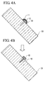
FIGS. 4A and 4B are views illustrating the method of repair according to a second embodiment of the present invention, wherein a process of impregnating a brazing material into a brazing material support by applying heat treatment is illustrated; -
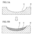
FIGS. 5A and 5B are views illustrating the method of repair according to a third embodiment of the present invention, wherein a process of placing a brazing material support is illustrated; -
FIGS. 6A and 6B are views illustrating the method of repair according to the third embodiment of the present invention, wherein a process of removing an excessive brazing material support and an excessive brazing material is illustrated; -
FIGS. 7A, 7B and 7C are views illustrating the method of repair according to a fourth embodiment of the present invention, wherein a process of removing a repair portion by scraping is illustrated; -
FIGS. 8A, 8B and 8C are views illustrating the method of repair according to the fourth embodiment of the present invention, wherein a process of removing an excessive brazing material is illustrated; -
FIGS. 9A, 9B and 9C are views illustrating the method of repair according to a fifth embodiment of the present invention; -
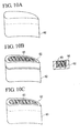
FIGS. 10A, 10B and 10C are views illustrating the method of repair according to a sixth embodiment of the present invention; -
FIGS. 11A, 11B and 11C are views illustrating the method of repair disclosed inPatent Document 3; -
FIG. 12 is a view illustrating a state in which an inclined base is repaired by brazing; and -
FIG. 13 is a view illustrating a state in which a curved surface of a base is repaired by brazing. - 1, 10, 30, 40, 50, 60, 70 ... Base; 2, 11, 71 ... Crack; 3 ... Removal portion; 4, 12, 32, 44, 52 ... Brazing material support; 5, 13, 33, 45, 64, 73, 81, 82 ... Brazing material; 41 ... Main body; 42 ... Protrusion; 43, 63 ... Groove, 51, 62 ... Exchange component; 72 ... Equivalent-to-base material
- Hereinafter, the present invention is described in detail on the basis of the embodiments illustrated in the accompanying drawings.
-
FIGS. 1A to 3B are the views illustrating the procedures of the method of repair according to a first embodiment. As shown inFIG. 1A , the first embodiment is a method for repairing abase 1 in which cracks 2 have developed. Examples of thebase 1 include a stator vane of a gas turbine; at the time of the periodic inspection of a gas turbine, the method of repair according to the present embodiment is implemented. However, thebase 1 is not limited to this; the base widely includes the components in which damages such ascracks 2 have developed. - As shown in
FIG. 1B , the portion of thebase 1 containing thecracks 2 is scraped away to form aremoval portion 3. Additionally, the oxide layer formed on thebase 1 is removed by this scraping. Theremoval portion 3 is formed in a shape permitting placing therein abrazing material support 4 to be described later. - In the first embodiment, the
base 1 is scraped so as for thecracks 2 to completely disappear; however, thebase 1 may be scraped so as for the cusps of thecracks 2 to partially remain. - Next, as shown in
FIG. 2A , thebrazing material support 4 is placed in theremoval portion 3. The placement of thebrazing material support 4 may be such that thebrazing material support 4 is simply placed at the bottom of theremoval portion 3, or such that thebrazing material support 4 is fixed to theremoval portion 3 by point welding or the like. - The
brazing material support 4 is made of a porous metal material. The porous metal material has a three-dimensional network structure in which the pores of the porous metal material are communicatively connected to each other. In thebrazing material support 4, the pores on the surface thereof are communicatively connected to the outside. As a porous metal material, there are some porous metal materials having a closed pore structure in which the pores thereof are mutually partitioned. However, in such a porous metal material having a closed pore structure, it is difficult to sufficiently impregnate the molten brazing material. Accordingly, in the present embodiment, a porous metal material having a three-dimensional network structure in which the pores of the porous metal material are communicatively connected to each other is used as thebrazing material support 4. On the bottom of theremoval portion 3, the oxide layer has been removed, and hence thebase 1 and thebrazing material support 4 directly contact with each other through the metals contained in thebase 1 and thesupport 4. - A porous metal material can be produced, for example, by sintering a metal powder. A porous metal material based on a sintered metal has a feature that the pore size can be made approximately as small as 1 µm, but the porosity thereof is as low as at most approximately 50%. In the present embodiment, it is preferable that the porosity be high, for the purpose of holding a predetermined amount of the molten brazing material in the interior of the porous metal material. Accordingly, in the present embodiment it is preferable to use a foam metal. In a foam metal, the pores of approximately 10 to 1000 µm in pore size can be formed with a porosity of at most approximately 97%. By controlling the pore size and the porosity, the mechanical strength of a foam metal can be controlled. In the present embodiment, after the completion of the repair, the
brazing material support 4 constitutes a portion of thebase 1, and hence it is necessary to select the pore size and the porosity by considering such a situation in addition to the holding of the brazing material. - The
brazing material support 4 is made of a material equivalent to thebase 1. In the stator vane of a gas turbine, a Co-base heat-resistant alloy has been used from the viewpoints of welding workability and thermal fatigue property; however, for the stator vanes of gas turbines increased in operational temperature and in size, Ni-base heat-resistant alloys come to be developed and used. When a Co-base heat-resistant alloy is used as thebase 1 in the present embodiment, thebrazing material support 4 is preferably made of a Co-base heat-resistant alloy equivalent to thebase 1. Alternatively, when a Ni-base heat-resistant alloy is used as thebase 1 in the present embodiment, thebrazing material support 4 is preferably made of a Ni-base heat-resistant alloy equivalent to thebase 1. - It is efficient to obtain the
brazing material support 4 by cutting out from a base material prepared separately. This is because the size of theremoval portion 3 is not specified. - The present applicant has proposed in Patent Document 4 a Ni-base heat-resistant alloy suitable for the stator vanes of gas turbines increased in operational temperature and in size. This Ni-base heat-resistant alloy (trade name: MGA2400) contains, in terms of the percentage by weight, 0.05 to 0.25% C, 18 to 25% Cr, 15 to 25% Co, one or two of 3.5% or less Mo and 5 to 10% W wherein the content of W +1/2Mo is 5 to 10%, 1.0 to 5.0% Ti, 1.0 to 4.0% Al, 0.5 to 4.5% Ta, 0.2 to 3.0% Nb, 0.005 to 0.10% Zr and 0.001 to 0.01% B, the balance comprising Ni and the inevitable impurities, wherein the alloy has a composition falling in a range enclosed by the lines connecting the following points sequentially in a coordinate system wherein the x-axis represents the (Al+Ti) amount and the y-axis represents the (W+1/2Mo) amount: the point A (Al+Ti: 3%, W+1/2Mo: 10%), the point B (Al+Ti: 5%, W+1/2Mo: 7.5%), the point C (Al+Ti: 5%, W-+1/2Mo: 5%), the point D (Al+Ti: 7%, W+1/2Mo: 5%) and the point E (Al+Ti: 7%, W+1/2Mo: 10%). Accordingly, when the
base 1 is a stator vane of a gas turbine, both thebase 1 and thebrazing material support 4 may be the alloys having the compositions falling within the above-described range. In other words, the above described term "equivalent" is not limited to the case where the chemical compositions are absolutely identical to each other. - Patent Document 4: Japanese Patent Laid-Open No.
8-127833 - Next, as shown in
FIG. 2B , thebrazing material support 4 and a portion of thebase 1 are covered with abrazing material 5 in a powder form. Thebrazing material 5 comprises an alloy lower in melting point than thebase 1 and thebrazing material support 4. For example, thebrazing material 5 can be obtained by adding a predetermined amount of one or two of B and Si, which are melting point-lowering elements, to the alloys constituting thebrazing material support 4 and thebase 1. It is not easy to handle thebrazing material 5 as a single powdery substance, and hence thebrazing material 5 preferably takes a paste form as a mixture with a liquid. - After the
brazing material support 4 and a portion of thebase 1 have been covered with thebrazing material 5, thebase 1 is moved into a not-shown heating furnace, and the brazing treatment is conducted. As the heating furnace, a vacuum heating furnace or an inert-gas furnace capable of making available an atmosphere of an inert gas is used; this is for the purpose of preventing the oxidation of thebase 1 and the like. - When the
brazing material 5 covering thebrazing material support 4 and a portion of thebase 1 is heated to a temperature at or above the melting point thereof, thebrazing material 5 is melted (FIG. 3A ). Themolten brazing material 5 penetrates into the pores formed in thebrazing material support 4 to be impregnated into thebrazing material support 4. In this case, it is understood that a capillary phenomenon takes place between the pores of thebrazing material support 4 and thebrazing material 5. Since thebrazing material 5 has been impregnated into thebrazing material support 4, even when thebase 1 is inclined, there is almost no possibility that thebrazing material 5 flows out from thebrazing material support 4 to the outside. The use of a vacuum heating furnace facilitates the impregnation of thebrazing material 5 into thebrazing material support 4. - In
FIG. 3A , theexcessive brazing material 5 not impregnated into thebrazing material support 4 is shown; however, theexcessive brazing material 5 is interconnected with thebrazing material 5 impregnated into thebrazing material support 4, and hence, even when thebase 1 is inclined, theexcessive brazing material 5 is hardly separated away from thebrazing material support 4. Additionally, by appropriately setting the initial amount of thebrazing material 5, the amount of theexcessive brazing material 5 can be reduced or made to disappear. - In the course of the brazing treatment, the
brazing material 5 is impregnated into thebrazing material support 4, and additionally, a part of thebrazing material 5 penetrates into the interstice between the bottom surface of thebrazing material support 4 and thebase 1 and into the interstice between the side surfaces of thebrazing material support 4 and thebase 1. Thisbrazing material 5 penetrates into the concerned places by passing through the pores in thebrazing material support 4 or by moving down the side surfaces of thebrazing material support 4. Thisbrazing material 5 contributes to the bonding between thebase 1 and thebrazing material support 4. - After heating for a predetermined time, the heating inside the heating furnace is terminated and the temperature inside the furnace is decreased down to normal temperature. In the course of the temperature decrease, element diffusion occurs between the
brazing material 5 and thebrazing material support 4 and between thebrazing material 5 and thebase 1, and thus, thebrazing material support 4 is strongly bonded to thebase 1. The pores of thebrazing material support 4 made of a porous metal material are filled with thebrazing material 5 to increase the mechanical strength of thebrazing material support 4. - After the
brazing material 5 has been solidified, as shown inFIG. 3B , thebrazing material support 4 protruding from thebase 1 and theexcessive brazing material 5 are removed. Thebrazing material support 4 which is impregnated with thebrazing material 5 and bonded to thebase 1 is left on thebase 1 as it is, so as to constitute therepair portion 6 of thebase 1. - As described above, according to the present embodiment, since the
molten brazing material 5 is impregnated into the interior of thebrazing material support 4, even when thebase 1 is placed with an inclination, thebrazing material 5 does not flow out to the surroundings. - Additionally, according to the present embodiment, since the
brazing material support 4 is made of a material equivalent to thebase 1, thebrazing material support 4 has a function of holding themolten brazing material 5 therein, and also functions after brazing as therepair portion 6 constituting a portion of thebase 1. - Additionally, according to the present embodiment, in the case where the
removal portion 3 is formed by scraping thebase 1, thebrazing material support 4 having a size corresponding to theremoval portion 3 can be prepared by cutting out from a base material, and hence the work efficiency is satisfactory. - It is to be noted that in the above-described example, in the course of the brazing treatment, the
brazing material 5 in a powder form is heated and melted to be impregnated into thebrazing material support 4, but alternatively, thebrazing material 5 may be beforehand impregnated into thebrazing material support 4. In this case, by immersing thebrazing material support 4 in themolten brazing material 5, thebrazing material 5 can be impregnated into thebrazing material support 4. - Next, with reference to
FIG. 4 , a second embodiment according to the present invention is described. - As shown in
FIG. 4A , acrack 11 is assumed to develop in aninclined base 10. - A
brazing material support 12 is placed on the base 10 so as to seal the opening of thecrack 11. In this case, for the purpose of preventing thebrazing material support 12 from moving downward, thebrazing material support 12 is preferably fixed to thebase 10 by point welding or the like. After thebrazing material support 12 has been placed, thebrazing material support 12 and a portion of the base 10 are covered with abrazing material 13 in a powder form. Thebrazing material support 12 and thebrazing material 13 may be the same as thebrazing material support 4 and thebrazing material 5 of the first embodiment, respectively. - After the
brazing material support 12 and a portion of the base 10 have been covered with thebrazing material 13, the brazing treatment is conducted in the same manner as in the first embodiment. Thebrazing material 13 is melted by heat treatment, and impregnated into the pores of thebrazing material support 12. Themolten brazing material 13 is also filled in the interstice between the brazingmaterial support 12 and thebase 10, and a part of the filledbrazing material 13 passes through the pores in the interior of thebrazing material support 12 and penetrates into the interior of thecrack 11 to be filled therein (FIG. 4B ). - In the above-described process, since the
brazing material 13 is impregnated into thebrazing material support 12, even when thebase 10 is inclined, there is almost no possibility that thebrazing material 13 flows out to the outside from thebrazing material support 12, in the same manner as in the first embodiment. - After the
brazing material 13 has been solidified, thebrazing material support 12 is removed. Thus, thecrack 11 is filled with thebrazing material 13 to complete the repair. - Additionally, the present invention includes a mode in which the
brazing material support 12 is not utilized as a portion of thebase 10, as in the present embodiment. - Next, with reference to
FIGS. 5A to 6B , a third embodiment according to the present invention is described. - As shown in
FIG. 5A , arecess 31 is formed in the central portion of abase 30. The surface (cross section) of therecess 31 forms a circular arc surface (curved surface). In the third embodiment, overlaying is applied to the surface of therecess 31. It is to be noted that inFIGS. 5A, 5B and6A, 6B , depiction of the cracks is omitted. - As shown in
FIG. 5B , abrazing material support 32 is placed on the surface of therecess 31. In the third embodiment, as thebrazing material support 32, a porous metal material having flexibility is used. When the shape of the surface of therecess 31 is known, abrazing material support 32 in conformity with the shape can be prepared. However, when therecess 31 is formed by scraping according to the development conditions of the cracks, the shape of therecess 31 is variable. Accordingly, by preparing thebrazing material support 32 using a porous metal material having flexibility, thebrazing material support 32 can be placed, without forming any interstice, on the surface of therecess 31. - Typical examples of the porous metal material having flexibility include metal wool, metal nonwoven fabric and metal gauze; any of these corresponds to a metal porous material provided with continuous pores and can function as the
brazing material support 32 of the present invention. The metal nonwoven fabric and metal gauze can be made to function as thebrazing material support 32 by laminating these thin materials. - After the
brazing material support 32 has been placed, a brazing material 33 is placed so as to cover thebrazing material support 32, as shown inFIG. 6A . The brazing material 33 is a material prepared by converting a powder into a paste form in the same manner as in the first embodiment and is placed along the surface of thebrazing material support 32. - After the brazing material 33 has been placed on the
brazing material support 32, the brazing material 33 is melted by heat treatment and is impregnated into the pores of thebrazing material support 32 in the same manner as in the first embodiment. The molten brazing material 33 also penetrates into the interstice between the brazingmaterial support 32 and the base 30 to be filled therein. In this process, the brazing material 33, other than the brazing material 33 which has also penetrated into the interstice between the brazingmaterial support 32 and the base 30 to be filled therein, is impregnated into thebrazing material support 32, and hence does not gather in the widthwise central portion of therecess 31. Accordingly, the molten brazing material 33 can be filled over the whole boundary between the brazingmaterial support 32 and thebase 30. The brazing material 33 contributes to the bonding between the base 30 and thebrazing material support 32. - After heating for a predetermined time, the heating inside the heating furnace is terminated and the temperature inside the furnace is decreased down to normal temperature. In the course of the temperature decrease, element diffusion occurs between the brazing material 33 and the
brazing material support 32, and thus, thebrazing material support 32 is strongly bonded to thebase 30. The pores of thebrazing material support 32 made of a porous metal material are filled with the brazing material 33. Hence thebrazing material support 32 is converted into an overlaidlayer 34 formed by filling the pores of thebrazing material support 32 with the brazing material 33 to increase the mechanical strength of the overlaidlayer 34. In the present embodiment, the overlaidlayer 34 is left as it is to constitute a portion of thebase 30. In this connection, needless to say, the overlaidlayer 34 can be processed into an optional shape. - As described above, the third embodiment repairs a curved surface, wherein the
brazing material support 32 is made of a porous metal material, and hence the brazing material 33 can be impregnated into thebrazing material support 32. Consequently, the brazing material 33 can be filled over the whole areas of the places, needing the brazing material 33, between the brazingmaterial support 32 and thebase 30. - Additionally, in the third embodiment, as the
brazing material support 32, a porous metal material having flexibility is used, and hence even when the repair portion is a curved surface, thebrazing material support 32 can be placed in the repair portion without leaving any interstice. - Next, with reference to
FIGS. 7A to 8C , a fourth embodiment according to the present invention is described. - The fourth embodiment repairs, as shown in
FIG. 7A , a base 40 in which aprotrusion 42 extending in the lengthwise direction is formed on the top surface of a rectangular parallelepipedmain body 41. - When the top surface of the
protrusion 42 is abraded as shown inFIG. 7B , as a results of a long-term use of thebase 40, it is necessary to repair the abraded portion. In the present embodiment, for example, the abraded portion is not repaired by overlaying, but theprotrusion 42 is replaced. For that purpose, as shown inFIG. 7C , the portion of themain body 41 on which portion theprotrusion 42 has been formed is scraped away to form agroove 43. Thegroove 43 has a width and a length allowing the insertion of a brazing material support 44 (FIG. 8A ) having a width and a length equal to those of theprotrusion 42. - After the
groove 43 has been formed, thebrazing material support 44 is inserted into thegroove 43 of thebase 40, as shown inFIG. 8A . Thebrazing material support 44 is preferably made of a foam metal similarly to thebrazing material support 4 of the first embodiment. However, this does not deny the use of a porous sintered metal. - After the
brazing material support 44 has been inserted into thegroove 43, abrazing material 45 is placed on themain body 41 so as to be in contact with the sides of thebrazing material support 44, as shown inFIG. 8B . Thebrazing material 45 is a material prepared by converting a powder into a paste form in the same manner as in the first embodiment. - After the
brazing material 45 has been placed on themain body 41, thebrazing material 45 is melted by heat treatment and is impregnated into the pores of the brazing material support 44 (FIG. 8C ) in the same manner as in the first embodiment. A part of themolten brazing material 45 penetrates into the interstice between the brazingmaterial support 44 in thegroove 43 and themain body 41 to be filled therein. In this process, thebrazing material 45, other than thebrazing material 45 which has also penetrated into the interstice between the brazingmaterial support 44 and themain body 41 to be filled therein, is impregnated into thebrazing material support 44, and hence there is no possibility that thebrazing material 45 flows out to the sides of themain body 41. Accordingly, themolten brazing material 45 can be filled over the whole boundaries between the brazingmaterial support 44 and themain body 41. Thebrazing material 45 contributes to the bonding between themain body 41 and thebrazing material support 44. - After heating for a predetermined time, the heating inside the heating furnace is terminated and the temperature inside the furnace is decreased down to normal temperature. In the course of the temperature decrease, element diffusion occurs between the brazing
material 45 and thebrazing material support 44 and between the brazingmaterial 45 andmain body 41, and thus, thebrazing material support 44 is strongly bonded to thebase 40. The pores of thebrazing material support 44 made of a porous metal material are filled with thebrazing material 45, and hence thebrazing material support 44 is converted into aprotrusion 42 formed by filling the pores of thebrazing material support 44 with thebrazing material 45 to increase the mechanical strength of theprotrusion 42. - Next, with reference to
FIG. 9 , a fifth embodiment according to the present invention is described. - The fifth embodiment can be applied when a portion of a vane-shaped
base 50 shown inFIG. 9A is remodeled and repaired into a different shape. - The portion on the posterior end side of the broken line on the base 50 shown in
FIG. 9A is removed by cutting. It is to be noted that the portion thinner in thickness of thebase 50 is referred to as the posterior portion and the portion thicker in thickness of thebase 50 is referred to as the anterior portion. - On the side where the posterior portion has been removed by cutting, as shown in
FIG. 9B , anexchange component 51 having a bulgy posterior end is placed. Theexchange component 51 is bonded to the base 50 with abrazing material support 52. Thebrazing material support 52 is made of the same porous metal material as shown in the first embodiment. However, in thebrazing material support 52, the pores of the porous metal material have been beforehand impregnated with a brazing material. For the purpose of beforehand filling the brazing material, the porous metal material is immersed in the molten brazing material, and then taken out, and thereafter the brazing material is solidified; thus thebrazing material support 52 can be prepared. In other words, thisbrazing material support 52 holds the brazing material beforehand. - As shown in
FIG. 9C , thebrazing material support 52 is sandwiched with thebase 50 and theexchange component 51. Under this condition, heat treatment is applied. The brazing material held by thebrazing material support 52 is melted by the heat treatment. The molten brazing material penetrates into the interstice between the base 50 and thebrazing material support 52 to be filled therein and the interstice between theexchange component 51 and thebrazing material support 52 to be filled therein. In this process, the brazing material, other than the brazing material which has penetrated into the interstice between the base 50 and thebrazing material support 52 to be filled therein and into the interstice between theexchange component 51 and thebrazing material support 52 to be filled therein, is impregnated into thebrazing material support 52, and hence there is no possibility that the brazing material flows out to the outside. The brazing material contributes to the bonding between the base 50 and thebrazing material support 52 and the bonding between theexchange component 51 and thebrazing material support 52. - After heating for a predetermined time, the heating inside the heating furnace is terminated and the temperature inside the furnace is decreased down to normal temperature. In the course of the temperature decrease, the
base 50 and theexchange component 51 are strongly bonded to each other through thebrazing material support 52. Thus, thebase 50 having a new shape with a bulgy posterior end can be obtained. - Next, with reference to
FIG. 10 , a sixth embodiment according to the present invention is described. - The sixth embodiment is also applied when a portion of a vane-shaped
base 60 shown inFIG. 10A is remodeled into a different shape, or is repaired. - The portion above the broken line of the base 60 shown in
FIG. 10A is removed by cutting. - In the portion removed by cutting, an
exchange component 62 approximately the same in exterior shape as the portion removed by cutting is placed, as shown inFIG. 10B . In theexchange component 62, agroove 63 having a shape approximately similar to the periphery of theexchange component 62 is formed with a predetermined depth. In thisgroove 63, abrazing material 64 is filled. Theexchange component 62 functions as a brazing material support and is made of the same porous metal material as shown in the first embodiment. - As shown in
FIG. 10B , under the condition that theexchange component 62 with thebrazing material 64 filled in thegroove 63 is placed on the top surface of thebase 60, heat treatment is conducted. Thebrazing material 64 filled in thegroove 63 is melted by the heat treatment. Themolten brazing material 64 penetrates into the pores formed in theexchange component 62 to be impregnated in the interior of theexchange component 62. A part of thebrazing material 64 impregnated in theexchange component 62 penetrates into the interstice between theexchange component 62 and the base 60 to be filled therein. In this process, thebrazing material 64, other than thebrazing material 64 which has penetrated into the interstice between theexchange component 62 and the base 60 to be filled therein, is impregnated into theexchange component 62, and hence there is no possibility that thebrazing material 64 flows out to the outside. Thebrazing material 64 contributes to the bonding between theexchange component 62 and thebase 60. - After heating for a predetermined time, the heating inside the heating furnace is terminated and the temperature inside the furnace is decreased down to normal temperature. In the course of the temperature decrease, the
exchange component 62 is strongly bonded to the base 60 through thebrazing material 64. Additionally, the pores of theexchange component 62 made of a porous metal material are filled with thebrazing material 64 to increase the mechanical strength of theexchange component 62 and theexchange component 62 functions as a portion of thebase 60.
Claims (10)
- A method of repair which repairs by brazing a repair portion of a base, the portion needing repair, wherein a brazing material support holding in the interior thereof a molten brazing material is brought into contact with the repair portion, and
under the condition that the brazing material support is in contact with the repair portion, the molten brazing material is solidified. - The method of repair according to claim 1, wherein under the condition that the brazing material in a powder form is brought into contact with the brazing material support, the brazing material is melted by heating to a temperature at or above the melting point of the brazing material.
- The method of repair according to claim 1, wherein under the condition that the brazing material support in the interior of which the brazing material has been beforehand held is brought into contact with the repair portion, the brazing material is melted by heating to a temperature at or above the melting point of the brazing material.
- The method of repair according to claim 1, wherein the brazing material support is a porous material having a three-dimensional network structure in which the pores of the porous material are communicatively connected to each other.
- The method of repair according to claim 4, wherein the porous material has flexibility.
- The method of repair according to claim 1, wherein after the brazing material has been solidified, the brazing material support is left to constitute a portion of the base.
- The method of repair according to claim 6, wherein the brazing material support is made of a material equivalent to the base.
- The method of repair according to claim 1, wherein a portion of the base is removed, and the brazing material support is placed at the portion of the base which portion has been subjected to the removal.
- The method of repair according to claim 8, wherein a portion of the base in which portion a crack has developed is removed.
- The method of repair according to claim 8, wherein the molten brazing material is solidified under the condition that an exchange component to be exchanged with the removed portion of the base is brought into contact with the brazing material support, and thus, the base and the exchange component are bonded to each other through the brazing material support.
Applications Claiming Priority (2)
| Application Number | Priority Date | Filing Date | Title |
|---|---|---|---|
| JP2007267666A JP5078537B2 (en) | 2007-10-15 | 2007-10-15 | Repair method |
| PCT/JP2008/068180 WO2009051031A1 (en) | 2007-10-15 | 2008-10-06 | Method of repair |
Publications (2)
| Publication Number | Publication Date |
|---|---|
| EP2186592A1 true EP2186592A1 (en) | 2010-05-19 |
| EP2186592A4 EP2186592A4 (en) | 2014-10-22 |
Family
ID=40567300
Family Applications (1)
| Application Number | Title | Priority Date | Filing Date |
|---|---|---|---|
| EP08839771.6A Withdrawn EP2186592A4 (en) | 2007-10-15 | 2008-10-06 | Method of repair |
Country Status (6)
| Country | Link |
|---|---|
| US (1) | US8042723B2 (en) |
| EP (1) | EP2186592A4 (en) |
| JP (1) | JP5078537B2 (en) |
| KR (1) | KR101137627B1 (en) |
| CN (1) | CN101626862B (en) |
| WO (1) | WO2009051031A1 (en) |
Cited By (7)
| Publication number | Priority date | Publication date | Assignee | Title |
|---|---|---|---|---|
| EP2591872A1 (en) * | 2011-11-11 | 2013-05-15 | Siemens Aktiengesellschaft | Remelting method and subsequent filling and resulting component |
| WO2015017092A1 (en) * | 2013-08-01 | 2015-02-05 | Siemens Energy, Inc. | Repair of a substrate with component supported filler |
| EP2450142A3 (en) * | 2010-11-08 | 2015-03-18 | General Electric Company | Improved system and method for brazing |
| WO2017060041A1 (en) * | 2015-10-07 | 2017-04-13 | Siemens Aktiengesellschaft | Repairing a part having cracks, and part |
| EP2412930A3 (en) * | 2010-07-28 | 2018-01-24 | General Electric Company | Turbine nozzle segment and method of repairing same |
| US11731206B2 (en) | 2019-02-11 | 2023-08-22 | Rolls-Royce Corporation | Repair of through-hole damage using braze sintered preform |
| US12194580B2 (en) | 2018-11-05 | 2025-01-14 | Rolls-Royce Corporation | Dual-walled components for a gas turbine engine |
Families Citing this family (28)
| Publication number | Priority date | Publication date | Assignee | Title |
|---|---|---|---|---|
| EP1857218A1 (en) * | 2006-05-18 | 2007-11-21 | Siemens Aktiengesellschaft | Method for repairing a component and a component |
| JP5254116B2 (en) * | 2009-04-17 | 2013-08-07 | 株式会社東芝 | Damage repair method for high temperature parts and high temperature parts |
| TW201438837A (en) * | 2013-02-27 | 2014-10-16 | Berndorf Band Gmbh | Method for repairing damage to a metal substrate |
| US9126279B2 (en) * | 2013-09-30 | 2015-09-08 | General Electric Company | Brazing method |
| JP6283210B2 (en) * | 2013-12-06 | 2018-02-21 | 株式会社豊田中央研究所 | Metal sheet material and brazing sheet material |
| US9254537B2 (en) | 2013-12-19 | 2016-02-09 | Siemens Energy, Inc. | Plural layer putty-powder/slurry application method for superalloy component crack vacuum furnace healing |
| CN104162762B (en) * | 2014-08-18 | 2016-08-24 | 青岛海之冠汽车配件制造有限公司 | Utilize the method that nickel-cobalt-molybdenum-manganese-base alloy carries out flywheel repairing |
| US9909197B2 (en) * | 2014-12-22 | 2018-03-06 | Semes Co., Ltd. | Supporting unit and substrate treating apparatus including the same |
| EP3216554B1 (en) * | 2016-03-09 | 2020-05-06 | MTU Aero Engines GmbH | Component with wear- resistant openings and depressions and method for producing the same |
| US10384787B2 (en) | 2016-06-23 | 2019-08-20 | Honeywell International Inc. | Forming an air data probe from a porous cover and brazing material |
| KR101668418B1 (en) * | 2016-06-29 | 2016-10-21 | 주식회사 에이더블유알에스 | Method for repairing windmill blade |
| US10265806B2 (en) * | 2016-10-04 | 2019-04-23 | General Electric Company | System and method for sealing internal channels defined in a component |
| US20180200817A1 (en) * | 2017-01-19 | 2018-07-19 | General Electric Company | Method of brazing and brazed article |
| US20180209288A1 (en) * | 2017-01-26 | 2018-07-26 | General Electric Company | Braze system, brazed article, and method for forming a brazed article |
| US11517969B2 (en) * | 2019-01-24 | 2022-12-06 | General Electric Company | Weld-brazing techniques |
| CN109848638B (en) * | 2019-01-25 | 2021-02-05 | 哈尔滨工业大学 | High-temperature alloy composite repair method and repair material |
| US11633797B2 (en) * | 2019-11-15 | 2023-04-25 | General Electric Company | Braze joints for a component and methods of forming the same |
| US12064827B1 (en) * | 2021-06-13 | 2024-08-20 | Garvey Holding LLC | Methods, systems, and apparatus for joining metallic fabrics |
| CN113560605A (en) * | 2021-07-27 | 2021-10-29 | 东台威达鑫精密模具有限公司 | Stamping die repairing method based on 3D printing technology |
| CN119658045A (en) * | 2023-09-12 | 2025-03-21 | 通用电气技术有限公司 | Braze repair method for reducing eutectic phases |
| US12576614B2 (en) | 2023-10-27 | 2026-03-17 | Ge Infrastructure Technology Llc | Porous metal coupon with thermal transfer structure for component and related component |
| US12605768B2 (en) | 2023-10-27 | 2026-04-21 | Ge Infrastructure Technology Llc | Porous metal coupon with low porosity region for repairing component, component with same and related method |
| US12502713B2 (en) | 2023-10-27 | 2025-12-23 | Ge Infrastructure Technology Llc | Porous metal coupon with sealed cavity for repairing component, component with same and related method |
| US12636741B2 (en) * | 2023-10-27 | 2026-05-26 | Ge Infrastructure Technology Llc | Braze repair using metal coupon with porous region |
| US12544845B2 (en) * | 2023-10-27 | 2026-02-10 | Ge Infrastructure Technology Llc | Porous metal coupon with braze material infiltration barrier for repairing component, component with same and related method |
| KR102893387B1 (en) * | 2023-11-29 | 2025-11-28 | 두산에너빌리티 주식회사 | Wide gap brazing method and wide gap brazing plug |
| US12528133B2 (en) | 2024-01-19 | 2026-01-20 | Ge Infrastructure Technology Llc | Metal coupon with braze reservoir for component, component with same and related method |
| US20250242409A1 (en) * | 2024-01-26 | 2025-07-31 | Rtx Corporation | Use of sacrificial surface during directed energy deposition repair process |
Family Cites Families (16)
| Publication number | Priority date | Publication date | Assignee | Title |
|---|---|---|---|---|
| US3031996A (en) * | 1958-02-03 | 1962-05-01 | George B Botvin | Reinforced brazed joint and method and means for making the same |
| US4285459A (en) * | 1979-07-31 | 1981-08-25 | Chromalloy American Corporation | High temperature braze repair of superalloys |
| JP2862487B2 (en) | 1994-10-31 | 1999-03-03 | 三菱製鋼株式会社 | Nickel-base heat-resistant alloy with excellent weldability |
| JPH09168927A (en) | 1995-12-19 | 1997-06-30 | Hitachi Ltd | Repair method for moving blade and stationary blade for gas turbine |
| JPH1143706A (en) | 1997-07-23 | 1999-02-16 | Ishikawajima Harima Heavy Ind Co Ltd | Repair method for metal parts |
| JPH1133832A (en) | 1997-07-23 | 1999-02-09 | Ishikawajima Harima Heavy Ind Co Ltd | Repair method of aluminum alloy parts |
| US6575702B2 (en) * | 2001-10-22 | 2003-06-10 | General Electric Company | Airfoils with improved strength and manufacture and repair thereof |
| JP2004283886A (en) | 2003-03-24 | 2004-10-14 | Mitsubishi Materials Corp | Brazing material |
| US7051435B1 (en) * | 2003-06-13 | 2006-05-30 | General Electric Company | Process for repairing turbine components |
| JP2005254283A (en) * | 2004-03-11 | 2005-09-22 | Toshiba Corp | How to repair wear-resistant members |
| JP2005305492A (en) * | 2004-04-20 | 2005-11-04 | Toshiba Corp | Diffusion brazing repair method and heat-resistant parts repaired using the repair method |
| JP4488830B2 (en) * | 2004-08-03 | 2010-06-23 | 株式会社東芝 | Regeneration treatment method of gas turbine stationary blade |
| US7335427B2 (en) * | 2004-12-17 | 2008-02-26 | General Electric Company | Preform and method of repairing nickel-base superalloys and components repaired thereby |
| EP1707301B1 (en) * | 2005-03-31 | 2008-06-18 | Siemens Aktiengesellschaft | Process for applying fibre mats on the surface or a recess of a component |
| US8703044B2 (en) | 2006-01-03 | 2014-04-22 | General Electric Company | Machine components and methods of fabricating and repairing |
| CN100546748C (en) * | 2007-01-26 | 2009-10-07 | 哈尔滨工业大学 | Electron beam brazing method for repairing superalloy blades |
-
2007
- 2007-10-15 JP JP2007267666A patent/JP5078537B2/en active Active
-
2008
- 2008-10-06 US US12/528,259 patent/US8042723B2/en active Active
- 2008-10-06 CN CN2008800030955A patent/CN101626862B/en active Active
- 2008-10-06 EP EP08839771.6A patent/EP2186592A4/en not_active Withdrawn
- 2008-10-06 KR KR1020097016028A patent/KR101137627B1/en active Active
- 2008-10-06 WO PCT/JP2008/068180 patent/WO2009051031A1/en not_active Ceased
Cited By (9)
| Publication number | Priority date | Publication date | Assignee | Title |
|---|---|---|---|---|
| EP2412930A3 (en) * | 2010-07-28 | 2018-01-24 | General Electric Company | Turbine nozzle segment and method of repairing same |
| EP2450142A3 (en) * | 2010-11-08 | 2015-03-18 | General Electric Company | Improved system and method for brazing |
| EP2591872A1 (en) * | 2011-11-11 | 2013-05-15 | Siemens Aktiengesellschaft | Remelting method and subsequent filling and resulting component |
| WO2013068161A1 (en) * | 2011-11-11 | 2013-05-16 | Siemens Aktiengesellschaft | Remelting method and subsequent refilling and component |
| WO2015017092A1 (en) * | 2013-08-01 | 2015-02-05 | Siemens Energy, Inc. | Repair of a substrate with component supported filler |
| WO2017060041A1 (en) * | 2015-10-07 | 2017-04-13 | Siemens Aktiengesellschaft | Repairing a part having cracks, and part |
| US12194580B2 (en) | 2018-11-05 | 2025-01-14 | Rolls-Royce Corporation | Dual-walled components for a gas turbine engine |
| US11731206B2 (en) | 2019-02-11 | 2023-08-22 | Rolls-Royce Corporation | Repair of through-hole damage using braze sintered preform |
| EP3693115B1 (en) * | 2019-02-11 | 2024-10-16 | Rolls-Royce Corporation | Repair of through-hole damage using braze sintered preform |
Also Published As
| Publication number | Publication date |
|---|---|
| EP2186592A4 (en) | 2014-10-22 |
| KR101137627B1 (en) | 2012-04-19 |
| KR20090106580A (en) | 2009-10-09 |
| WO2009051031A1 (en) | 2009-04-23 |
| US8042723B2 (en) | 2011-10-25 |
| CN101626862B (en) | 2012-11-28 |
| CN101626862A (en) | 2010-01-13 |
| JP5078537B2 (en) | 2012-11-21 |
| US20100187290A1 (en) | 2010-07-29 |
| JP2009095840A (en) | 2009-05-07 |
Similar Documents
| Publication | Publication Date | Title |
|---|---|---|
| US8042723B2 (en) | Method of repair | |
| EP3693115B1 (en) | Repair of through-hole damage using braze sintered preform | |
| EP0836904B1 (en) | Method of repairing metallic alloy articles, such as gas turbine engine components | |
| US8087565B2 (en) | Process of filling openings in a component | |
| EP1623787B1 (en) | Method of repairing a stator vane of gas turbine without removing all the cracks ; repaired gas turbine | |
| JP7532496B2 (en) | System and method for repairing hot gas turbine blades | |
| JP3166856B2 (en) | Powder metallurgy repair method | |
| CN101987385B (en) | Brazing process and material for repairing a component | |
| US20130086785A1 (en) | Hybrid repair plugs and repair methods incorporating the same | |
| CN105149597B (en) | The reparation of metal or alloy component or connecting method and component that is repaired or being coupled | |
| KR20180136402A (en) | Method of welding superalloys | |
| RU2703666C2 (en) | Turbine engine component manufacturing method | |
| EP2492044A1 (en) | A method of repairing a component | |
| RU2763528C1 (en) | Replacing the turbine aerodynamic profile section with metal pre-sintered soldering billet | |
| CN106170368B (en) | Structure for superalloy materials is brazed | |
| US20150174707A1 (en) | Plural layer putty-powder/slurry application method for superalloy component crack vacuum furnace healing | |
| RU2572948C2 (en) | Composite powder for combination or surfacing by diffusion brazing of components from superalloys | |
| EP1705338A1 (en) | Method for repairing parts composed of superalloys | |
| US20090286102A1 (en) | Induced capillary action brazing using metallic foam matrix | |
| JP2005305492A (en) | Diffusion brazing repair method and heat-resistant parts repaired using the repair method | |
| US7658315B2 (en) | Process of brazing superalloy components | |
| JP2022527776A (en) | Tip repair of turbine components using composite tip boron-based pre-sintered preforms |
Legal Events
| Date | Code | Title | Description |
|---|---|---|---|
| PUAI | Public reference made under article 153(3) epc to a published international application that has entered the european phase |
Free format text: ORIGINAL CODE: 0009012 |
|
| 17P | Request for examination filed |
Effective date: 20090825 |
|
| AK | Designated contracting states |
Kind code of ref document: A1 Designated state(s): AT BE BG CH CY CZ DE DK EE ES FI FR GB GR HR HU IE IS IT LI LT LU LV MC MT NL NO PL PT RO SE SI SK TR |
|
| AX | Request for extension of the european patent |
Extension state: AL BA MK RS |
|
| DAX | Request for extension of the european patent (deleted) | ||
| A4 | Supplementary search report drawn up and despatched |
Effective date: 20140924 |
|
| RIC1 | Information provided on ipc code assigned before grant |
Ipc: B23K 3/06 20060101ALI20140918BHEP Ipc: F02C 7/00 20060101ALI20140918BHEP Ipc: F01D 9/02 20060101ALI20140918BHEP Ipc: B23K 1/00 20060101AFI20140918BHEP Ipc: F01D 25/00 20060101ALI20140918BHEP |
|
| RAP1 | Party data changed (applicant data changed or rights of an application transferred) |
Owner name: MITSUBISHI HITACHI POWER SYSTEMS, LTD. |
|
| 17Q | First examination report despatched |
Effective date: 20150626 |
|
| STAA | Information on the status of an ep patent application or granted ep patent |
Free format text: STATUS: THE APPLICATION IS DEEMED TO BE WITHDRAWN |
|
| 18D | Application deemed to be withdrawn |
Effective date: 20151107 |