EP2186549B1 - Athletic apparatus with non-parallel linear sliding track - Google Patents
Athletic apparatus with non-parallel linear sliding track Download PDFInfo
- Publication number
- EP2186549B1 EP2186549B1 EP08019632A EP08019632A EP2186549B1 EP 2186549 B1 EP2186549 B1 EP 2186549B1 EP 08019632 A EP08019632 A EP 08019632A EP 08019632 A EP08019632 A EP 08019632A EP 2186549 B1 EP2186549 B1 EP 2186549B1
- Authority
- EP
- European Patent Office
- Prior art keywords
- tracks
- rod
- pedal
- mechanisms
- frame
- Prior art date
- Legal status (The legal status is an assumption and is not a legal conclusion. Google has not performed a legal analysis and makes no representation as to the accuracy of the status listed.)
- Not-in-force
Links
Images


Classifications
-
- A—HUMAN NECESSITIES
- A63—SPORTS; GAMES; AMUSEMENTS
- A63B—APPARATUS FOR PHYSICAL TRAINING, GYMNASTICS, SWIMMING, CLIMBING, OR FENCING; BALL GAMES; TRAINING EQUIPMENT
- A63B22/00—Exercising apparatus specially adapted for conditioning the cardio-vascular system, for training agility or co-ordination of movements
- A63B22/20—Exercising apparatus specially adapted for conditioning the cardio-vascular system, for training agility or co-ordination of movements using rollers, wheels, castors or the like, e.g. gliding means, to be moved over the floor or other surface, e.g. guide tracks, during exercising
- A63B22/201—Exercising apparatus specially adapted for conditioning the cardio-vascular system, for training agility or co-ordination of movements using rollers, wheels, castors or the like, e.g. gliding means, to be moved over the floor or other surface, e.g. guide tracks, during exercising for moving a support element in reciprocating translation, i.e. for sliding back and forth on a guide track
- A63B22/205—Exercising apparatus specially adapted for conditioning the cardio-vascular system, for training agility or co-ordination of movements using rollers, wheels, castors or the like, e.g. gliding means, to be moved over the floor or other surface, e.g. guide tracks, during exercising for moving a support element in reciprocating translation, i.e. for sliding back and forth on a guide track in a substantially vertical plane, e.g. for exercising against gravity
-
- A—HUMAN NECESSITIES
- A63—SPORTS; GAMES; AMUSEMENTS
- A63B—APPARATUS FOR PHYSICAL TRAINING, GYMNASTICS, SWIMMING, CLIMBING, OR FENCING; BALL GAMES; TRAINING EQUIPMENT
- A63B22/00—Exercising apparatus specially adapted for conditioning the cardio-vascular system, for training agility or co-ordination of movements
- A63B22/0002—Exercising apparatus specially adapted for conditioning the cardio-vascular system, for training agility or co-ordination of movements involving an exercising of arms
- A63B22/001—Exercising apparatus specially adapted for conditioning the cardio-vascular system, for training agility or co-ordination of movements involving an exercising of arms by simultaneously exercising arms and legs, e.g. diagonally in anti-phase
-
- A—HUMAN NECESSITIES
- A63—SPORTS; GAMES; AMUSEMENTS
- A63B—APPARATUS FOR PHYSICAL TRAINING, GYMNASTICS, SWIMMING, CLIMBING, OR FENCING; BALL GAMES; TRAINING EQUIPMENT
- A63B22/00—Exercising apparatus specially adapted for conditioning the cardio-vascular system, for training agility or co-ordination of movements
- A63B22/0025—Particular aspects relating to the orientation of movement paths of the limbs relative to the body; Relative relationship between the movements of the limbs
- A63B2022/0028—Particular aspects relating to the orientation of movement paths of the limbs relative to the body; Relative relationship between the movements of the limbs the movement path being non-parallel to the body-symmetrical-plane, e.g. support elements moving at an angle to the body-symmetrical-plane
-
- A—HUMAN NECESSITIES
- A63—SPORTS; GAMES; AMUSEMENTS
- A63B—APPARATUS FOR PHYSICAL TRAINING, GYMNASTICS, SWIMMING, CLIMBING, OR FENCING; BALL GAMES; TRAINING EQUIPMENT
- A63B21/00—Exercising apparatus for developing or strengthening the muscles or joints of the body by working against a counterforce, with or without measuring devices
- A63B21/005—Exercising apparatus for developing or strengthening the muscles or joints of the body by working against a counterforce, with or without measuring devices using electromagnetic or electric force-resisters
Definitions
- the present invention relates to athletic apparatus, and particular to an athletic apparatus with a non-parallel linear sliding track and provides complicated exercise for user's hands and feet.
- a plenty of athletic apparatuss are developed for the purposes of body fitness or rehabilitation.
- Athletic apparatuss such as a stair climber can provide an exercise for a user's feet by treading up and down on pedals only.
- Athletic apparatuss such as an elliptical trainer can provide an exercise for both hands and feet.
- Pedals of the elliptical trainer fixed to a linking rod can not be moved alone.
- the exercise style of the stair climber is still an upwards and downwards exercise and the style of the elliptical trainer is still an elliptical movement and the pedals still can not be slid on the supporting linking rod.
- EP 1 834 674 A2 refers to a climber mechanism having arm handles that move in synchronism with the motion of foot pedals and enabling linear foot movement at a simulated climbing angle.
- the present invention provides an athletic apparatus according to claim 1.
- the athletic apparatus provides exercise for a user's hands and feet, especially a non-parallel linear slide of good athletic effect for the user's feet.
- the athletic apparatus 1 includes a frame 10, a pair of separated tracks 3 and 4, a pair of pedal mechanisms, a pair of separated rocker arm mechanisms, two transmitting mechanisms, and a damping mechanism.
- the frame 10 has a base 18 which includes a front bottom rod 11 and a rear bottom rod 13 separated from each other.
- the front bottom rod 11 is formed as a standing rod 12
- a control panel 121 is installed to a top of the standing rod 12.
- the users can operate the athletic apparatus 1 through the control panel 121.
- An axle rod 14 is formed near an upper end of the standing rod 12, handles 15 for holding by the users are formed respectively between two ends of the axle rod 14 and a middle bottom rod 19 of the base 18. Installation portions 131 and 132 are formed separately to the rear bottom rod 13.
- the tracks 3 and 4 of the same structure are arranged to a left and right side of the athletic apparatus 1 respectively. Bottom ends of track 3 and 4 are fixed to the installation portions 131 and 132 respectively, while upper ends of the tracks 3 and 4 are fixed to an inclined supporting rod 16 of the frame 10 so that the left and right tracks are at an predetermined angle to the ground.
- a main characteristic of the tracks is that the tracks are made of non-parallel linear arrangement. The distances of the two tracks 3, 4 become smaller and smaller from the lower ends thereof to the upper ends thereof.
- the design of the tracks will have the users experienced the most natural exercise for feet, it is also an ergonomic design capable of protecting user's heels from being hurt.
- the left and right pedal mechanisms of the same structure have pedal bases 5 and 6, supporters 51 and 61 linked to the pedal bases 5 and 6, and pedals 52 and 62 for treading by the users respectively.
- the pedal bases 5 and 6 are slidably installed to the inclined tracks 3 and 4 respectively and capable of being slid up and down along the tracks.
- the left and right rocker arm mechanisms of the same structure have rocker arms 7 and 8 respectively.
- Upper ends 71 and 81 of the rocker arms 7 and 8 respectively are pivoted to the axle rod 14, and handles 70 and 80 are arranged to the rocker arms 7 and 8 respectively for holding by the users.
- Lower ends 72 and 82 of the rocker arms 7 and 8 are pivoted to linking rods 73 and 83 through universal connectors 74 and 84 (which are capable of rotating in Y and Z axes) respectively.
- Another ends of the linking rods 73 and 83 are also pivoted to the pedal bases 5 and 6 through universal connectors 75 and 85. Therefore, the left and right rocker arm mechanisms and the left and right pedal mechanisms can be moved identically.
- a first transmitting mechanism has a pulley 91 which is rotatably installed to the inclined supporting rod 16, said pulley 91 is positioned near to the upper ends of the tracks below.
- Said first transmitting mechanism further comprises a steel rope 92 which is wound on said pulley 91. Two ends of the steel rope 92 are connected to the left and right pedal bases 5 and 6 respectively so that the pedal bases 5 and 6 can be slid back and forth, up and down against each other alternately.
- the second transmitting mechanism has two timing belts 21, 22 and an elastic belt 23 linking the two timing belts 21, 22. Outer ends of the timing belts 21, 22 are connected to the lower ends 72, 82 of the rocker arms 7 and 8 respectively so that the left and right rocker arm mechanisms can be swung back and forth alternately with an axle center of the axle rod 14.
- a shaft rod 24 is installed to the frame 10.
- a belt wheel 25 is installed to a middle position of the shaft rod 24, and two gear wheels 26, 27 are installed to two ends of the shaft rod 24.
- the gear wheels 26, 27 have single direction bearing.
- the timing belts 21, 22 clench the teeth of the gear wheels 26 and 27 respectively.
- Two wheels 28, 29 are pivoted to two ends of the front bottom rod 11.
- the elastic belt 23 linking the timing belts 21, 22 also winds the wheels 28 and 29.
- the left and right rocker arms 7 and 8 can be moved back and forth against each other alternately.
- the damping mechanism includes a load wheel 101 and an electro-magnetic brake 102.
- the load wheel 101 is linked to the belt wheel 25.
- the damping mechanism can provide a resistance. The resistance can be pre-selected on the control panel 121.
- the main characteristic of the left and right tracks 3 and 4 is made of at least one non-parallel linear track.
- the tracks 3 and 4 of the embodiment of the present invention are non-parallel linear tracks; which are made of two parallel linear pipes 31, 32 and 41, 42 and combined by linking bodies 33, 43 respectively.
- the upper ends of the linear pipes are all fixed to a common linking unit 161 which is fixed to an upper end of the inclined supporting rod 16.
- the linking bodies 33 and 43 and the lower ends of the tracks are fixed to the installation portions 131 and 132 so that the tracks are installed to the frame 10 at an angle A to the ground as shown in Fig. 6 .
- a center line 17 illustrated between the oppositely installed tracks 3 and 4 indicates a longitudinal direction of the base 18 of the present invention.
- the tracks 3, 4 are non-parallel. After the tracks 3, 4 are installed to be between the rear bottom rod 13 and the center line 17, they are downwards and expanded in the distances therebetween. Namely, the upper ends 30, 40 of the tracks 3, 4, respectively are near the center line 17 and the lower end 39, 49 thereof are far away from the center line 17 so that the opening between the lower ends of the tracks 3, 4 are faced outwards and has an angle B with the center line 17.
- a user When operating the athletic apparatus 1 according to the present invention, a user (not illustrated) stands on the pedals 52 and 62 with both feet respectively and holds the handles 70 and 80 with both hands respectively. While the user overcomes the resistance of the load wheel 101, the rocker arm mechanisms are pulled back and forth and the pedals mechanisms are moved back and forth, up and down against each other alternately in the same time.
- the athletic apparatus 1 can provide a composite body exercise for hands and feet of the users. Also, by the design of the non-parallel linear tracks 3 and 4, the pedals bases 5 and 6 will be moved along the non-parallel linear tracks to present non-parallel linear track in the movement so that feet of the user can exercise smoothly by moving outwards and downwards together and moving forth and upwards together.
- the pedals 52 and 62 are parallel to the ground on the non-parallel tracks 3 and 4 at a static status.
- the pedals 52 and 62 can retain in a horizontal state so that the upwards and downwards movement along the track are smooth and safe.
- the athletic apparatus 1 has a simple structure and provides a physical training on muscles of user's arms and feet. Especially to the design of the tracks 3 and 4, the users can exercise inwards and outwards with a non-parallel linear track. Moreover, the rocker arm mechanisms can drive the load wheel 101 through the belt wheel 25 by the link of two timing belts on the same axis to the belt wheel 25. On the other hand, the rocker arm mechanisms can drive the corresponding pedal mechanisms on the left and right tracks 3, 4 synchronously by the link of linking rods 73 and 83 so that the athletic apparatus 1 can archive an anticipated purpose and effect.
- FIG. 9 and 10 Another embodiment of the present invention is illustrated in Figs. 9 and 10 , it is illustrated that the first transmitting mechanism is rotatably installed to the tracks 3, 4 and are positioned to the pulleys 93, 94 of the tracks 3, 4, respectively (as shown in Fig. 10 ).
- the lower ends of the tracks 3, 4 are rotatably installed to the installation portions 131, 132.
- the tracks 3, 4 are swingable along the axles 133, 134 of the installation portions 131, 132, respectively.
- the upper ends of the tracks 3, 4 are retained by a screwing unit 20 which is installed to the frame 10.
- the tracks 3, 4 are supported and positioned by the screwing unit 20 so as to form with an incline angle A with the ground.
- the screwing unit 20 has an outer tube 201 retained to the frame 10, an inner tube 202 telescopically moved in the outer tube 201 and a motor 203 for driving the inner tube 202.
- a top end of the inner tube 202 serves to pivotally support a connecting unit 161 which serve to position the upper ends of the tracks 3, 4.
- a moving tracks 3, 4 will rotate along the axles 133, 134, respectively so that the user can adjust a proper inclined angle A.
- the structure of the present invention is novel and inventive to the prior art structure.
- the non-parallel linear tracks are different from the prior art linear and parallel tracks so as to increase the effect in exercise.
- the present invention is better than the prior art structure.
Landscapes
- Health & Medical Sciences (AREA)
- Cardiology (AREA)
- Vascular Medicine (AREA)
- General Health & Medical Sciences (AREA)
- Physical Education & Sports Medicine (AREA)
- Rehabilitation Tools (AREA)
Abstract
Description
- The present invention relates to athletic apparatus, and particular to an athletic apparatus with a non-parallel linear sliding track and provides complicated exercise for user's hands and feet.
- A plenty of athletic apparatuss are developed for the purposes of body fitness or rehabilitation. Athletic apparatuss such as a stair climber can provide an exercise for a user's feet by treading up and down on pedals only. Athletic apparatuss such as an elliptical trainer can provide an exercise for both hands and feet. Pedals of the elliptical trainer fixed to a linking rod can not be moved alone. Although the stair climber and the elliptical trainer are well developed and improved, the exercise style of the stair climber is still an upwards and downwards exercise and the style of the elliptical trainer is still an elliptical movement and the pedals still can not be slid on the supporting linking rod.
- For instance,
EP 1 834 674 A2 - Accordingly, the present invention provides an athletic apparatus according to
claim 1. The athletic apparatus provides exercise for a user's hands and feet, especially a non-parallel linear slide of good athletic effect for the user's feet. - The various objects and advantages of the present invention will be more readily understood from the following detailed description when read in conjunction with the appended drawing.
-
-
Fig. 1 is a pictorial drawing of an embodiment of an athletic apparatus of the present invention. -
Fig. 2 is a pictorial drawing of the embodiment of the present invention viewing from a side. -
Fig. 3 is a pictorial drawing of the embodiment of the present invention viewing from another side to theFig. 2 . -
Fig. 4 is a top view showing pedal mechanisms at a back and front positions of tracks. -
Fig. 5 is a rear view showing the pedal mechanisms at the back and front positions of the tracks. -
Fig. 6 shows drawing of theFig. 5 from a side. -
Fig. 7 shows the non-parallel linear tracks oppositely installed to a center line. -
Fig. 8 is a pictorial drawing of the athletic apparatus viewing from a back side. -
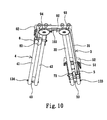
Fig. 9 is a lateral view of an athletic apparatus in another embodiment of the present invention, wherein a screw rod screwedly moves along the track. -
Fig. 10 is a front view which shows that the pedals inFig. 9 are positioned on the track with one being at the front side and another being at a rear side. - In order that those skilled in the art can further understand the present invention, a description will be provided in the following in details. However, these descriptions and the appended drawings are only used to cause those skilled in the art to understand the objects, features, and characteristics of the present invention, but not to be used to confine the scope of the present invention defined in the appended claims.
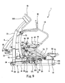
- With reference to
Figs. 1 ,2 ,3 , and8 , anathletic apparatus 1 according to the present invention is illustrated. Theathletic apparatus 1 includes aframe 10, a pair ofseparated tracks - The
frame 10 has abase 18 which includes afront bottom rod 11 and arear bottom rod 13 separated from each other. Thefront bottom rod 11 is formed as a standingrod 12, acontrol panel 121 is installed to a top of the standingrod 12. The users can operate theathletic apparatus 1 through thecontrol panel 121. Anaxle rod 14 is formed near an upper end of the standingrod 12, handles 15 for holding by the users are formed respectively between two ends of theaxle rod 14 and amiddle bottom rod 19 of thebase 18.Installation portions rear bottom rod 13. - The
tracks athletic apparatus 1 respectively. Bottom ends oftrack installation portions tracks rod 16 of theframe 10 so that the left and right tracks are at an predetermined angle to the ground. A main characteristic of the tracks is that the tracks are made of non-parallel linear arrangement. The distances of the twotracks - The left and right pedal mechanisms of the same structure have
pedal bases supporters pedal bases pedals pedal bases inclined tracks - The left and right rocker arm mechanisms of the same structure have
rocker arms Upper ends rocker arms axle rod 14, and handles 70 and 80 are arranged to therocker arms Lower ends rocker arms rods universal connectors 74 and 84 (which are capable of rotating in Y and Z axes) respectively. Another ends of the linkingrods pedal bases universal connectors - A first transmitting mechanism has a
pulley 91 which is rotatably installed to the inclined supportingrod 16, saidpulley 91 is positioned near to the upper ends of the tracks below. Said first transmitting mechanism further comprises asteel rope 92 which is wound on saidpulley 91. Two ends of thesteel rope 92 are connected to the left andright pedal bases pedal bases - Referring to
Figs. 1 to 3 , a second transmitting mechanism is illustrated. The second transmitting mechanism has twotiming belts elastic belt 23 linking the twotiming belts timing belts lower ends rocker arms axle rod 14. Ashaft rod 24 is installed to theframe 10. Abelt wheel 25 is installed to a middle position of theshaft rod 24, and twogear wheels shaft rod 24. Thegear wheels timing belts gear wheels wheels front bottom rod 11. Theelastic belt 23 linking thetiming belts wheels right rocker arms - The damping mechanism includes a
load wheel 101 and an electro-magnetic brake 102. By the link of atransmitting belt 103, theload wheel 101 is linked to thebelt wheel 25. When thehandles control panel 121. - With reference to
Figs. 4 to 6 , the main characteristic of the left andright tracks tracks linear pipes bodies common linking unit 161 which is fixed to an upper end of the inclined supportingrod 16. The linkingbodies installation portions frame 10 at an angle A to the ground as shown inFig. 6 . - Referring to
Fig. 7 , acenter line 17 illustrated between the oppositely installedtracks base 18 of the present invention. Thetracks tracks rear bottom rod 13 and thecenter line 17, they are downwards and expanded in the distances therebetween. Namely, the upper ends 30, 40 of thetracks center line 17 and thelower end center line 17 so that the opening between the lower ends of thetracks center line 17. - When operating the
athletic apparatus 1 according to the present invention, a user (not illustrated) stands on thepedals handles load wheel 101, the rocker arm mechanisms are pulled back and forth and the pedals mechanisms are moved back and forth, up and down against each other alternately in the same time. - The
athletic apparatus 1 according to the present invention can provide a composite body exercise for hands and feet of the users. Also, by the design of the non-parallellinear tracks - The
pedals non-parallel tracks athletic apparatus 1, as shown inFig. 5 , thepedals - The
athletic apparatus 1 according to the present invention has a simple structure and provides a physical training on muscles of user's arms and feet. Especially to the design of thetracks load wheel 101 through thebelt wheel 25 by the link of two timing belts on the same axis to thebelt wheel 25. On the other hand, the rocker arm mechanisms can drive the corresponding pedal mechanisms on the left andright tracks rods athletic apparatus 1 can archive an anticipated purpose and effect. - Another embodiment of the present invention is illustrated in
Figs. 9 and10 , it is illustrated that the first transmitting mechanism is rotatably installed to thetracks pulleys tracks Fig. 10 ). The lower ends of thetracks installation portions tracks axles installation portions tracks unit 20 which is installed to theframe 10. Thetracks unit 20 so as to form with an incline angle A with the ground. The screwingunit 20 has anouter tube 201 retained to theframe 10, aninner tube 202 telescopically moved in theouter tube 201 and amotor 203 for driving theinner tube 202. A top end of theinner tube 202 serves to pivotally support a connectingunit 161 which serve to position the upper ends of thetracks inner tube 202 moves out of theouter tube 201 with a predetermined amount, a movingtracks axles - The structure of the present invention is novel and inventive to the prior art structure. The non-parallel linear tracks are different from the prior art linear and parallel tracks so as to increase the effect in exercise. Thus, the present invention is better than the prior art structure.
Claims (10)
- An athletic apparatus comprising:a frame (10) placed on a level ground;a pair of left (3) and right (4) tracks of the same structure fixed to the frame (10) at a predetermined angle to the ground; the tracks being linear;a pair of left and right pedal mechanisms of the same structure including pedals (52, 62) for treading by a user's feet and being installed to the left and right tracks respectively;a pair of left and right rocker arm mechanisms of the same structure being movably installed to the frame (10) and the left and right pedal mechanisms so as to be moved identically with the pedal mechanisms;characterised in thatthe tracks (3, 4) are non-parallel,the pedal mechanisms further being moved up and down along the non-parallel linear tracks (3, 4);wherein by the tracks are non-parallel linear tracks, the users experiences the most natural feet exercise and an ergonomic design capable of protecting user's heels from being hurt.
- The athletic apparatus (1) as claimed in claim 1, wherein the frame (10) has a base (18) which includes a front bottom rod (11) and a rear bottom rod (13) separated from each other; the front bottom rod (11) is formed as a standing rod, (12) a control panel (121) is installed to a top of the standing rod (12); the users can operate the athletic apparatus (1) through the control panel (121); an axle rod (14) is formed near an upper end of the standing rod (12), handles (15) for holding by the user's hands are formed respectively between two ends of the axle rod (14) and a middle bottom rod (19) of the base (18); installation portions (131,132) and are formed separately to the rear bottom rod (13).
- The athletic apparatus (1) as claimed in claim 1, wherein the left and right rocker arm mechanisms have rocker arms (7,8) with upper ends (71,81) thereof pivoted to the axle rod (14), and handles (70,80) arranged to the rocker arms (7,8) respectively for holding by the user; lower ends (72,82) of the rocker arms (7,8) are pivoted to linking rods (73,83) through universal connectors (74,84) respectively; another ends of the linking rods (73,83) are pivoted to the left and right pedal mechanisms through universal connectors (75,85); therefore, the left and right rocker arm mechanisms and the left and right pedal mechanisms can be moved identically.
- The athletic apparatus (1) as claimed in claim 1, wherein the left and right pedal mechanisms have pedal bases (5,6), supporters (51,61) installed on the pedal bases (5,6), and pedals (52,62) for treading by the user's feet respectively; the pedal bases (5,6) are slidably installed to the non-parallel linear tracks (3,4) respectively and capable of being slid up and down along the tracks.
- The athletic apparatus (1) as claimed in claim 1, wherein bottom ends of the tracks (3,4) are fixed to the installation portions (131,132) of the rear bottom rods (13) respectively, while upper ends of the tracks (3,4) are fixed to an inclined supporting rod (16) of the frame (10) so that the left and right tracks (3,4) are at an predetermined angle to the ground.
- The athletic apparatus (1) as claimed in claim 1 including a first transmitting mechanism, a second transmitting mechanism and a damping mechanism, said first transmitting mechanism has a pulley (91) which is rotatably installed to the inclined supporting rod (16) of said frame (10), said pulley (91) is positioned near to the upper ends of the tracks below; said first transmitting mechanism further comprises a steel rope (92) which is wound on said pulley (91); two ends of the steel rope (92) are connected to the left and right pedals (5,6) respectively so that the pedals can be slid back and forth, up and down against each other alternately; said second transmitting mechanism has two timing belts (21,22) and an elastic belt (23) linking the two timing belts (21,22); outer ends of the timing belts (21,22) are connected to the lower ends (72,82) of the rocker arms (7,8) respectively so that the left and right rocker arm mechanisms can be swung back and forth alternately with an axle center of the axle rod (14); a shaft rod (24) is installed to the frame (10); a belt wheel (25) is installed to a middle position of the shaft rod (24), and two gear wheels (26,27) are installed to two ends of the shaft rod (24); the gear wheels (26,27) have single direction bearing; the timing belts (21,22) clench the teeth of the gear wheels (26,27) respectively; two wheels (28,29) are pivoted to two ends of the front bottom rod (11), and the elastic belt (23) linking the timing belts (21,22) winds the wheel (28,29); by the linking of the second transmitting mechanism, the left and right rocker arm mechanisms can be moved back and forth against each other alternately; said damping mechanism includes a load wheel (101) and an electro-magnetic brake (102); by the link of a transmitting belt (103), the load wheel (101) is linked to the belt wheel (25); when the handles (70,80) are swung back and forth alternately, the damping mechanism can provide a resistance.
- The athletic apparatus (1) as claimed in claim 1, wherein the left and right tracks are respectively made of two combined linear pipes (31,32 and 41,42).
- The athletic apparatus (1) as claimed in claim 2, wherein a center line of a longitudinal direction of the base is defined as a center line (17) and the left and right tracks (3,4) are oppositely installed beside the line; the tracks (3,4 )are non-parallel linear tracks; after the tracks (3,4) are installed to be between the rear bottom rod (13) and the center line (17), they are downwards and expanded in the distances therebetween; namely, the upper ends (30,40) of the tracks (3,4), respectively are near the center line (17) and the lower end (39,49) thereof are far away from the center line (17) so that the opening between the lower ends of the tracks (3,4) are faced outwards and has an angle (8) with the center line (17).
- The athletic apparatus (1) as claimed in claim 1, wherein the pedals (52,62) are parallel to the ground on the tracks (3,4) at a static status; the pedals (52,62) can tilt towards each other with a predetermined angle so that the upwards and downwards movements of the pedals (52,62) along the non-parallel linear tracks are smooth and safe; for not to affect the balance of a user by an non-parallel linear trace from the pedal, the pedal (52,62) is retained in horizontal state with the non-parallel linear trace of the tracks, and thus the pedal (52,62) is moved up and down along a non-parallel trace.
- The athletic apparatus (1) as claimed in claim 6, wherein the first transmitting mechanism is rotatably installed to the tracks (3,4) and are positioned to the pulleys (93,94) of the tracks (3,4) respectively; the lower ends of the tracks (3,4) are rotatably installed to the installation portions (131,132) the tracks (3,4) are swingable along the axles (133,134) of the installation portions (131,132), respectively; the upper ends of the tracks (3,4) are retained by a screwing unit (20) which is installed to the frame (10); the tracks (3,4) are supported and positioned by the screwing unit (20) so as to form with an incline angle (A) with the ground; said screwing unit (20) has an outer tube (201) retained to the frame (10), an inner tube (202) telescopically moved in the outer tube (201) and a motor (203) for driving the inner tube (202); a top end of the inner tube (202) serves to pivotally support a connecting unit (161) which serve to position the upper ends of the tracks (3,4); when the inner tube (202) moves out of the outer tube (201) with a predetermined amount, a moving tracks (3,4) will rotate along the axles (133,134), respectively so that the user can adjust a proper inclined angle.
Priority Applications (2)
| Application Number | Priority Date | Filing Date | Title |
|---|---|---|---|
| AT08019632T ATE529166T1 (en) | 2008-11-10 | 2008-11-10 | SPORTS DEVICE WITH NON-PARALLEL LINEAR SLIDE RAIL |
| EP08019632A EP2186549B1 (en) | 2008-11-10 | 2008-11-10 | Athletic apparatus with non-parallel linear sliding track |
Applications Claiming Priority (1)
| Application Number | Priority Date | Filing Date | Title |
|---|---|---|---|
| EP08019632A EP2186549B1 (en) | 2008-11-10 | 2008-11-10 | Athletic apparatus with non-parallel linear sliding track |
Publications (2)
| Publication Number | Publication Date |
|---|---|
| EP2186549A1 EP2186549A1 (en) | 2010-05-19 |
| EP2186549B1 true EP2186549B1 (en) | 2011-10-19 |
Family
ID=40433838
Family Applications (1)
| Application Number | Title | Priority Date | Filing Date |
|---|---|---|---|
| EP08019632A Not-in-force EP2186549B1 (en) | 2008-11-10 | 2008-11-10 | Athletic apparatus with non-parallel linear sliding track |
Country Status (2)
| Country | Link |
|---|---|
| EP (1) | EP2186549B1 (en) |
| AT (1) | ATE529166T1 (en) |
Cited By (2)
| Publication number | Priority date | Publication date | Assignee | Title |
|---|---|---|---|---|
| CN103285555A (en) * | 2013-06-17 | 2013-09-11 | 宁波市鄞州风名工业产品设计有限公司 | Digital fitness chair |
| CN103301607A (en) * | 2013-06-17 | 2013-09-18 | 宁波市鄞州风名工业产品设计有限公司 | Body-building chair |
Family Cites Families (3)
| Publication number | Priority date | Publication date | Assignee | Title |
|---|---|---|---|---|
| US6758790B1 (en) * | 2002-09-04 | 2004-07-06 | Northland Industries, Inc. | Low impact walking/jogging exercise machine |
| US7594877B2 (en) | 2006-03-13 | 2009-09-29 | Brunswick Corporation | Climber appliance |
| CN200991530Y (en) * | 2006-12-15 | 2007-12-19 | 张煌东 | Marching guide structure improvement of leg motion body-building apparatus |
-
2008
- 2008-11-10 EP EP08019632A patent/EP2186549B1/en not_active Not-in-force
- 2008-11-10 AT AT08019632T patent/ATE529166T1/en not_active IP Right Cessation
Cited By (4)
| Publication number | Priority date | Publication date | Assignee | Title |
|---|---|---|---|---|
| CN103285555A (en) * | 2013-06-17 | 2013-09-11 | 宁波市鄞州风名工业产品设计有限公司 | Digital fitness chair |
| CN103301607A (en) * | 2013-06-17 | 2013-09-18 | 宁波市鄞州风名工业产品设计有限公司 | Body-building chair |
| CN103301607B (en) * | 2013-06-17 | 2015-11-18 | 宁波市鄞州风名工业产品设计有限公司 | A kind of ab lounge |
| CN103285555B (en) * | 2013-06-17 | 2015-12-02 | 宁波市鄞州风名工业产品设计有限公司 | Numeral ab lounge |
Also Published As
| Publication number | Publication date |
|---|---|
| ATE529166T1 (en) | 2011-11-15 |
| EP2186549A1 (en) | 2010-05-19 |
Similar Documents
| Publication | Publication Date | Title |
|---|---|---|
| US7806808B2 (en) | Athletic apparatus with non-parallel linear sliding track | |
| US7695408B2 (en) | Elliptical exercise device and methods of use | |
| EP3097957B1 (en) | Excercise machine with multiple exercising modes | |
| US10661115B2 (en) | Stationary manual exercise sled | |
| US7618350B2 (en) | Elliptical exercise machine with adjustable ramp | |
| US7780577B2 (en) | Pendulous exercise device | |
| US7278955B2 (en) | Exercise device for cross training | |
| US7731635B2 (en) | Cross training exercise device | |
| US7507186B2 (en) | Exercise methods and apparatus with elliptical foot motion | |
| US7530930B2 (en) | Exercise apparatus | |
| CA2956938C (en) | Exercise apparatus with oscillating tilt system | |
| US20090111663A1 (en) | Elliptical exercise machine | |
| US20120077645A1 (en) | Exercising device | |
| US20060281604A1 (en) | Cross training exercise device | |
| US20100093497A1 (en) | Athletic apparatus with non-linear sliding track | |
| US8033961B2 (en) | Athletic apparatus with non-linear sliding track | |
| US7670268B1 (en) | Exercise methods and apparatus with elliptical foot motion | |
| EP1793901A1 (en) | Exercise apparatus for simulating skating movement | |
| EP2186549B1 (en) | Athletic apparatus with non-parallel linear sliding track | |
| CN202966563U (en) | Running type exercise bicycle | |
| US11305150B2 (en) | Simulated hill-climbing exercise apparatus | |
| EP2186550B1 (en) | Athletic apparatus with non-linear sliding track | |
| US10926132B1 (en) | Linkage mechanism with handles linked to elliptical motion trajectory | |
| TWI558441B (en) | Exercise device | |
| TWM494011U (en) | Composite fitness equipment for rehabilitation |
Legal Events
| Date | Code | Title | Description |
|---|---|---|---|
| PUAI | Public reference made under article 153(3) epc to a published international application that has entered the european phase |
Free format text: ORIGINAL CODE: 0009012 |
|
| 17P | Request for examination filed |
Effective date: 20081110 |
|
| AK | Designated contracting states |
Kind code of ref document: A1 Designated state(s): AT BE BG CH CY CZ DE DK EE ES FI FR GB GR HR HU IE IS IT LI LT LU LV MC MT NL NO PL PT RO SE SI SK TR |
|
| AX | Request for extension of the european patent |
Extension state: AL BA MK RS |
|
| AKX | Designation fees paid |
Designated state(s): AT BE BG CH CY CZ DE DK EE ES FI FR GB GR HR HU IE IS IT LI LT LU LV MC MT NL NO PL PT RO SE SI SK TR |
|
| GRAP | Despatch of communication of intention to grant a patent |
Free format text: ORIGINAL CODE: EPIDOSNIGR1 |
|
| GRAS | Grant fee paid |
Free format text: ORIGINAL CODE: EPIDOSNIGR3 |
|
| GRAA | (expected) grant |
Free format text: ORIGINAL CODE: 0009210 |
|
| AK | Designated contracting states |
Kind code of ref document: B1 Designated state(s): AT BE BG CH CY CZ DE DK EE ES FI FR GB GR HR HU IE IS IT LI LT LU LV MC MT NL NO PL PT RO SE SI SK TR |
|
| REG | Reference to a national code |
Ref country code: GB Ref legal event code: FG4D |
|
| REG | Reference to a national code |
Ref country code: CH Ref legal event code: EP |
|
| REG | Reference to a national code |
Ref country code: IE Ref legal event code: FG4D |
|
| REG | Reference to a national code |
Ref country code: DE Ref legal event code: R096 Ref document number: 602008010537 Country of ref document: DE Effective date: 20111215 |
|
| REG | Reference to a national code |
Ref country code: NL Ref legal event code: VDEP Effective date: 20111019 |
|
| LTIE | Lt: invalidation of european patent or patent extension |
Effective date: 20111019 |
|
| REG | Reference to a national code |
Ref country code: AT Ref legal event code: MK05 Ref document number: 529166 Country of ref document: AT Kind code of ref document: T Effective date: 20111019 |
|
| PG25 | Lapsed in a contracting state [announced via postgrant information from national office to epo] |
Ref country code: NO Free format text: LAPSE BECAUSE OF FAILURE TO SUBMIT A TRANSLATION OF THE DESCRIPTION OR TO PAY THE FEE WITHIN THE PRESCRIBED TIME-LIMIT Effective date: 20120119 Ref country code: BE Free format text: LAPSE BECAUSE OF FAILURE TO SUBMIT A TRANSLATION OF THE DESCRIPTION OR TO PAY THE FEE WITHIN THE PRESCRIBED TIME-LIMIT Effective date: 20111019 Ref country code: IS Free format text: LAPSE BECAUSE OF FAILURE TO SUBMIT A TRANSLATION OF THE DESCRIPTION OR TO PAY THE FEE WITHIN THE PRESCRIBED TIME-LIMIT Effective date: 20120219 Ref country code: LT Free format text: LAPSE BECAUSE OF FAILURE TO SUBMIT A TRANSLATION OF THE DESCRIPTION OR TO PAY THE FEE WITHIN THE PRESCRIBED TIME-LIMIT Effective date: 20111019 |
|
| PG25 | Lapsed in a contracting state [announced via postgrant information from national office to epo] |
Ref country code: SI Free format text: LAPSE BECAUSE OF FAILURE TO SUBMIT A TRANSLATION OF THE DESCRIPTION OR TO PAY THE FEE WITHIN THE PRESCRIBED TIME-LIMIT Effective date: 20111019 Ref country code: SE Free format text: LAPSE BECAUSE OF FAILURE TO SUBMIT A TRANSLATION OF THE DESCRIPTION OR TO PAY THE FEE WITHIN THE PRESCRIBED TIME-LIMIT Effective date: 20111019 Ref country code: NL Free format text: LAPSE BECAUSE OF FAILURE TO SUBMIT A TRANSLATION OF THE DESCRIPTION OR TO PAY THE FEE WITHIN THE PRESCRIBED TIME-LIMIT Effective date: 20111019 Ref country code: LV Free format text: LAPSE BECAUSE OF FAILURE TO SUBMIT A TRANSLATION OF THE DESCRIPTION OR TO PAY THE FEE WITHIN THE PRESCRIBED TIME-LIMIT Effective date: 20111019 Ref country code: PT Free format text: LAPSE BECAUSE OF FAILURE TO SUBMIT A TRANSLATION OF THE DESCRIPTION OR TO PAY THE FEE WITHIN THE PRESCRIBED TIME-LIMIT Effective date: 20120220 Ref country code: GR Free format text: LAPSE BECAUSE OF FAILURE TO SUBMIT A TRANSLATION OF THE DESCRIPTION OR TO PAY THE FEE WITHIN THE PRESCRIBED TIME-LIMIT Effective date: 20120120 Ref country code: HR Free format text: LAPSE BECAUSE OF FAILURE TO SUBMIT A TRANSLATION OF THE DESCRIPTION OR TO PAY THE FEE WITHIN THE PRESCRIBED TIME-LIMIT Effective date: 20111019 |
|
| PGFP | Annual fee paid to national office [announced via postgrant information from national office to epo] |
Ref country code: DE Payment date: 20111229 Year of fee payment: 4 |
|
| PG25 | Lapsed in a contracting state [announced via postgrant information from national office to epo] |
Ref country code: CY Free format text: LAPSE BECAUSE OF FAILURE TO SUBMIT A TRANSLATION OF THE DESCRIPTION OR TO PAY THE FEE WITHIN THE PRESCRIBED TIME-LIMIT Effective date: 20111019 Ref country code: MC Free format text: LAPSE BECAUSE OF NON-PAYMENT OF DUE FEES Effective date: 20111130 |
|
| PGFP | Annual fee paid to national office [announced via postgrant information from national office to epo] |
Ref country code: IT Payment date: 20111130 Year of fee payment: 4 |
|
| PG25 | Lapsed in a contracting state [announced via postgrant information from national office to epo] |
Ref country code: SK Free format text: LAPSE BECAUSE OF FAILURE TO SUBMIT A TRANSLATION OF THE DESCRIPTION OR TO PAY THE FEE WITHIN THE PRESCRIBED TIME-LIMIT Effective date: 20111019 Ref country code: DK Free format text: LAPSE BECAUSE OF FAILURE TO SUBMIT A TRANSLATION OF THE DESCRIPTION OR TO PAY THE FEE WITHIN THE PRESCRIBED TIME-LIMIT Effective date: 20111019 Ref country code: CZ Free format text: LAPSE BECAUSE OF FAILURE TO SUBMIT A TRANSLATION OF THE DESCRIPTION OR TO PAY THE FEE WITHIN THE PRESCRIBED TIME-LIMIT Effective date: 20111019 Ref country code: BG Free format text: LAPSE BECAUSE OF FAILURE TO SUBMIT A TRANSLATION OF THE DESCRIPTION OR TO PAY THE FEE WITHIN THE PRESCRIBED TIME-LIMIT Effective date: 20120119 Ref country code: EE Free format text: LAPSE BECAUSE OF FAILURE TO SUBMIT A TRANSLATION OF THE DESCRIPTION OR TO PAY THE FEE WITHIN THE PRESCRIBED TIME-LIMIT Effective date: 20111019 |
|
| PLBE | No opposition filed within time limit |
Free format text: ORIGINAL CODE: 0009261 |
|
| STAA | Information on the status of an ep patent application or granted ep patent |
Free format text: STATUS: NO OPPOSITION FILED WITHIN TIME LIMIT |
|
| REG | Reference to a national code |
Ref country code: IE Ref legal event code: MM4A |
|
| PG25 | Lapsed in a contracting state [announced via postgrant information from national office to epo] |
Ref country code: PL Free format text: LAPSE BECAUSE OF FAILURE TO SUBMIT A TRANSLATION OF THE DESCRIPTION OR TO PAY THE FEE WITHIN THE PRESCRIBED TIME-LIMIT Effective date: 20111019 Ref country code: RO Free format text: LAPSE BECAUSE OF FAILURE TO SUBMIT A TRANSLATION OF THE DESCRIPTION OR TO PAY THE FEE WITHIN THE PRESCRIBED TIME-LIMIT Effective date: 20111019 |
|
| REG | Reference to a national code |
Ref country code: FR Ref legal event code: ST Effective date: 20120817 |
|
| 26N | No opposition filed |
Effective date: 20120720 |
|
| PG25 | Lapsed in a contracting state [announced via postgrant information from national office to epo] |
Ref country code: IE Free format text: LAPSE BECAUSE OF NON-PAYMENT OF DUE FEES Effective date: 20111110 |
|
| REG | Reference to a national code |
Ref country code: DE Ref legal event code: R097 Ref document number: 602008010537 Country of ref document: DE Effective date: 20120720 |
|
| PG25 | Lapsed in a contracting state [announced via postgrant information from national office to epo] |
Ref country code: AT Free format text: LAPSE BECAUSE OF FAILURE TO SUBMIT A TRANSLATION OF THE DESCRIPTION OR TO PAY THE FEE WITHIN THE PRESCRIBED TIME-LIMIT Effective date: 20111019 |
|
| PG25 | Lapsed in a contracting state [announced via postgrant information from national office to epo] |
Ref country code: MT Free format text: LAPSE BECAUSE OF FAILURE TO SUBMIT A TRANSLATION OF THE DESCRIPTION OR TO PAY THE FEE WITHIN THE PRESCRIBED TIME-LIMIT Effective date: 20111019 |
|
| PG25 | Lapsed in a contracting state [announced via postgrant information from national office to epo] |
Ref country code: FR Free format text: LAPSE BECAUSE OF NON-PAYMENT OF DUE FEES Effective date: 20111219 Ref country code: ES Free format text: LAPSE BECAUSE OF FAILURE TO SUBMIT A TRANSLATION OF THE DESCRIPTION OR TO PAY THE FEE WITHIN THE PRESCRIBED TIME-LIMIT Effective date: 20120130 |
|
| PG25 | Lapsed in a contracting state [announced via postgrant information from national office to epo] |
Ref country code: LU Free format text: LAPSE BECAUSE OF NON-PAYMENT OF DUE FEES Effective date: 20111110 |
|
| PG25 | Lapsed in a contracting state [announced via postgrant information from national office to epo] |
Ref country code: FI Free format text: LAPSE BECAUSE OF FAILURE TO SUBMIT A TRANSLATION OF THE DESCRIPTION OR TO PAY THE FEE WITHIN THE PRESCRIBED TIME-LIMIT Effective date: 20111019 |
|
| REG | Reference to a national code |
Ref country code: CH Ref legal event code: PL |
|
| GBPC | Gb: european patent ceased through non-payment of renewal fee |
Effective date: 20121110 |
|
| PG25 | Lapsed in a contracting state [announced via postgrant information from national office to epo] |
Ref country code: LI Free format text: LAPSE BECAUSE OF NON-PAYMENT OF DUE FEES Effective date: 20121130 Ref country code: CH Free format text: LAPSE BECAUSE OF NON-PAYMENT OF DUE FEES Effective date: 20121130 |
|
| PG25 | Lapsed in a contracting state [announced via postgrant information from national office to epo] |
Ref country code: IT Free format text: LAPSE BECAUSE OF NON-PAYMENT OF DUE FEES Effective date: 20121110 |
|
| REG | Reference to a national code |
Ref country code: DE Ref legal event code: R119 Ref document number: 602008010537 Country of ref document: DE Effective date: 20130601 |
|
| PG25 | Lapsed in a contracting state [announced via postgrant information from national office to epo] |
Ref country code: TR Free format text: LAPSE BECAUSE OF FAILURE TO SUBMIT A TRANSLATION OF THE DESCRIPTION OR TO PAY THE FEE WITHIN THE PRESCRIBED TIME-LIMIT Effective date: 20111019 |
|
| PG25 | Lapsed in a contracting state [announced via postgrant information from national office to epo] |
Ref country code: DE Free format text: LAPSE BECAUSE OF NON-PAYMENT OF DUE FEES Effective date: 20130601 Ref country code: HU Free format text: LAPSE BECAUSE OF FAILURE TO SUBMIT A TRANSLATION OF THE DESCRIPTION OR TO PAY THE FEE WITHIN THE PRESCRIBED TIME-LIMIT Effective date: 20111019 |
|
| PG25 | Lapsed in a contracting state [announced via postgrant information from national office to epo] |
Ref country code: GB Free format text: LAPSE BECAUSE OF NON-PAYMENT OF DUE FEES Effective date: 20121110 |