EP2185848B1 - Thermal protection sleeve with knit thermal protection features and method of construction thereof - Google Patents
Thermal protection sleeve with knit thermal protection features and method of construction thereof Download PDFInfo
- Publication number
- EP2185848B1 EP2185848B1 EP08798576.8A EP08798576A EP2185848B1 EP 2185848 B1 EP2185848 B1 EP 2185848B1 EP 08798576 A EP08798576 A EP 08798576A EP 2185848 B1 EP2185848 B1 EP 2185848B1
- Authority
- EP
- European Patent Office
- Prior art keywords
- wall
- sleeve
- knit
- flap
- opening
- Prior art date
- Legal status (The legal status is an assumption and is not a legal conclusion. Google has not performed a legal analysis and makes no representation as to the accuracy of the status listed.)
- Active
Links
Images


Classifications
-
- F—MECHANICAL ENGINEERING; LIGHTING; HEATING; WEAPONS; BLASTING
- F16—ENGINEERING ELEMENTS AND UNITS; GENERAL MEASURES FOR PRODUCING AND MAINTAINING EFFECTIVE FUNCTIONING OF MACHINES OR INSTALLATIONS; THERMAL INSULATION IN GENERAL
- F16L—PIPES; JOINTS OR FITTINGS FOR PIPES; SUPPORTS FOR PIPES, CABLES OR PROTECTIVE TUBING; MEANS FOR THERMAL INSULATION IN GENERAL
- F16L57/00—Protection of pipes or objects of similar shape against external or internal damage or wear
- F16L57/06—Protection of pipes or objects of similar shape against external or internal damage or wear against wear
-
- D—TEXTILES; PAPER
- D04—BRAIDING; LACE-MAKING; KNITTING; TRIMMINGS; NON-WOVEN FABRICS
- D04B—KNITTING
- D04B1/00—Weft knitting processes for the production of fabrics or articles not dependent on the use of particular machines; Fabrics or articles defined by such processes
- D04B1/22—Weft knitting processes for the production of fabrics or articles not dependent on the use of particular machines; Fabrics or articles defined by such processes specially adapted for knitting goods of particular configuration
-
- F—MECHANICAL ENGINEERING; LIGHTING; HEATING; WEAPONS; BLASTING
- F01—MACHINES OR ENGINES IN GENERAL; ENGINE PLANTS IN GENERAL; STEAM ENGINES
- F01N—GAS-FLOW SILENCERS OR EXHAUST APPARATUS FOR MACHINES OR ENGINES IN GENERAL; GAS-FLOW SILENCERS OR EXHAUST APPARATUS FOR INTERNAL-COMBUSTION ENGINES
- F01N13/00—Exhaust or silencing apparatus characterised by constructional features
- F01N13/14—Exhaust or silencing apparatus characterised by constructional features having thermal insulation
-
- F—MECHANICAL ENGINEERING; LIGHTING; HEATING; WEAPONS; BLASTING
- F16—ENGINEERING ELEMENTS AND UNITS; GENERAL MEASURES FOR PRODUCING AND MAINTAINING EFFECTIVE FUNCTIONING OF MACHINES OR INSTALLATIONS; THERMAL INSULATION IN GENERAL
- F16L—PIPES; JOINTS OR FITTINGS FOR PIPES; SUPPORTS FOR PIPES, CABLES OR PROTECTIVE TUBING; MEANS FOR THERMAL INSULATION IN GENERAL
- F16L57/00—Protection of pipes or objects of similar shape against external or internal damage or wear
- F16L57/04—Protection of pipes or objects of similar shape against external or internal damage or wear against fire or other external sources of extreme heat
-
- D—TEXTILES; PAPER
- D10—INDEXING SCHEME ASSOCIATED WITH SUBLASSES OF SECTION D, RELATING TO TEXTILES
- D10B—INDEXING SCHEME ASSOCIATED WITH SUBLASSES OF SECTION D, RELATING TO TEXTILES
- D10B2403/00—Details of fabric structure established in the fabric forming process
- D10B2403/01—Surface features
- D10B2403/011—Dissimilar front and back faces
- D10B2403/0113—One surface including hollow piping or integrated straps, e.g. for inserts or mountings
-
- D—TEXTILES; PAPER
- D10—INDEXING SCHEME ASSOCIATED WITH SUBLASSES OF SECTION D, RELATING TO TEXTILES
- D10B—INDEXING SCHEME ASSOCIATED WITH SUBLASSES OF SECTION D, RELATING TO TEXTILES
- D10B2505/00—Industrial
- D10B2505/12—Vehicles
-
- F—MECHANICAL ENGINEERING; LIGHTING; HEATING; WEAPONS; BLASTING
- F01—MACHINES OR ENGINES IN GENERAL; ENGINE PLANTS IN GENERAL; STEAM ENGINES
- F01N—GAS-FLOW SILENCERS OR EXHAUST APPARATUS FOR MACHINES OR ENGINES IN GENERAL; GAS-FLOW SILENCERS OR EXHAUST APPARATUS FOR INTERNAL-COMBUSTION ENGINES
- F01N2260/00—Exhaust treating devices having provisions not otherwise provided for
- F01N2260/20—Exhaust treating devices having provisions not otherwise provided for for heat or sound protection, e.g. using a shield or specially shaped outer surface of exhaust device
-
- F—MECHANICAL ENGINEERING; LIGHTING; HEATING; WEAPONS; BLASTING
- F01—MACHINES OR ENGINES IN GENERAL; ENGINE PLANTS IN GENERAL; STEAM ENGINES
- F01N—GAS-FLOW SILENCERS OR EXHAUST APPARATUS FOR MACHINES OR ENGINES IN GENERAL; GAS-FLOW SILENCERS OR EXHAUST APPARATUS FOR INTERNAL-COMBUSTION ENGINES
- F01N2310/00—Selection of sound absorbing or insulating material
- F01N2310/14—Wire mesh fabric, woven glass cloth or the like
Definitions
- This invention relates generally to sleeves for protecting elongate members and more particularly to knit tubular protection sleeves.
- Knit tubular sleeves that provide protection from external elements and that provide a barrier to heat radiation from elongate members, such as exhaust pipes, wires and tubing, contained within the sleeves, are known.
- the sleeves are commonly knit from abrasion resistant, heat resistant, or fire retardant yarns to withstand relatively high temperatures and to allow portions of the sleeve to expand radially.
- the sleeves are commonly constructed having a continuous, closed tubular wall, such that the sleeves must be slid in sock-like fashion over the item being protected. Given the closed tubular wall construction, sometimes multiple sleeves are used in combination with one another to accommodate protrusions, e.g., sensors, or members branching from the item being protected, wherein adjacent ends of the sleeves are fastened to one another on opposite sides of the respective obstacle.
- some sleeves have an opening formed in the closed wall to accommodate the respective protrusion and/or member branching from the item being protected, or to facilitate locating the sleeve in a stationary position relative to a protrusion from the item being protected.
- the closed wall In order to form the opening, or in some cases multiple openings, the closed wall must be slit, thereby resulting in frayed, loose ends of the yarns forming the closed wall. This generally results in unraveling of the yarns forming the sleeve, thereby reducing its ability to perform as intended and reducing its useful life.
- openings in secondary cutting and sewing operations.
- the cut edges forming the opening are sewn to reduce the likelihood of their unraveling.
- these secondary operations add cost to the manufacturing process.
- the sewn edges provide a potential origin for future unraveling, should the stitches come loose or broken during use.
- Knit sleeves manufactured in accordance with the present invention overcome or greatly minimize any limitations of the known sleeves described above.
- US 1,786,862 discloses a knitted stocking having an opening to accommodate the heel of a wearer integrally knitted in, said opening optionally being divided into two by a strap extending substantially parallel to a longitudinal axis of the stocking.
- US 4,961,418 discloses knitted fabric sleeve-like appliances for wrapping hand, elbow region, ankle region and knee region of a user, respectively and each formed with an opening for protrusion of thumb, elbow, heel and knee of the user.
- the invention provides a sleeve for protecting elongate members and for inhibiting heat radiation outwardly from at least a portion thereof as specified in claim 1.
- the sleeve may have at least one elongate flap knit from the yarn or yarns, wherein the flap is foldable to abut at least a portion of the wall to provide a multilayered wall.
- the wall of the sleeve may be knit having a first knit stitch pattern and the flap may be knit having a second knit stitch pattern, the first knit stitch pattern being different from the second knit stitch pattern.
- a method of constructing a sleeve for protecting an elongate member received therein and for providing a thermal barrier to heat radiation is also provided as specified in claim 9.
- the method preferably includes weft knitting the sleeve on a flat bed knitting machine.
- the method may include knitting at least one elongate flap knit with the one or more yarns, with the flap being foldable to abut at least a portion of the wall to provide a multilayered wall.
- Figure 1 illustrates a knit thermal sleeve 10 constructed according to one embodiment of the invention for protecting heat generating elongate members, such as an exhaust pipe 11, for example.
- the sleeve 10 has an elongate body, shown generally at 12, having a wall 14 extending along a longitudinal axis 16, shown here as conforming to a bend in the pipe 11, between finish knit opposite ends 18, 20 of the sleeve 10.
- the sleeve 10 has at least one, and represented here, by way of example and without limitation, as a plurality of thermal vent openings, referred to hereafter as openings 22, wherein the openings 22 are knit in the same continuous knitting operation used to knit the body 12.
- the openings 22 can be knit having any size and shape using a predetermined series of needle and stitch transfers, as desired, to provide the desired amount of heat radiation outwardly from the sleeve 10.
- the sleeve 10 can be constructed having the wall 14 suitably sized and positioned on the pipe 11 to provide a thermal barrier to heat radiation radially outwardly from the wall 14, while the openings 22 can also be suitably sized and configured to provide an intended path promoting heat radiation radially outwardly through the openings 22.
- the sleeve 10 provides a thermal barrier in the region of the wall 14 and a thermal flow path in the region of the openings 22.
- the ability to knit the openings 22 concurrently with the wall 14 in a single knitting operation negates the necessity to perform secondary operations to form the openings 22.
- each opening 22 has a periphery 24 formed with continuous, uncut yarn or yarns, and thus, the yarn or yarns forming the respective opening 22 does not unravel, thereby providing the sleeve 10 with a long and useful life.
- a low clearance heat barrier is provided, and in addition, with the wall 14 being formed of interlinked knit stitches, the wall 14 is able to be readily contoured to expand and contract as necessary to conform to the contour of the pipe 11.
- the wall 14 is knit from one or more yarns interlinked with one another by a plurality of knit stitches.
- the yarn or yarns referred to hereafter simply as yarns unless otherwise specified, can be provided having any suitable characteristics and of any suitable material, such as monofilaments and/or multifilaments of any suitable Tex and material, including fire resistant and/or fire retardant (FR) yarns. If high temperature ratings are desired along with FR capabilities, then some presently preferred yarn materials include basalt, m-Aramid (Nomex, Conex, Kermel), p-aramid (Kevlar, Twaron, Technora), PE1 (Ultem), PPS, and PEEK, for example.
- the yarns can be knit in any suitable stitch and pattern in discrete areas of the sleeve 10.
- one portion of the wall 14 could be knit with one type of yarn in one knit stitch pattern, and another discrete portion of the wall 14 can be knit with another type of yarn having another knit stitch pattern.
- a multitude of configurations and performance characteristics are possible, depending on the types of yarns and knit stitch patterns used in constructing the sleeve 10.
- a sleeve 10 constructed in accordance with another presently preferred embodiment, wherein the same reference numerals are used to indicate similar features as identified in Figure 1 can be constructed with the wall 14 having multiple thermal wall layers, with one layer being configured as an inner layer 26 for abutment with the pipe 11, and the other layer being configured as an outer layer 28.
- the inner layer 26 is formed by a reverse folded elongate flap 30 (shown reverse folded in Figure 3 ).
- the flap 30 is knit from at least some of the same yarns used to knit the outer layer 28 of the wall 14, and is shown here as being formed as a continuous knit extension of the outer layer 28 and extending from one of the ends 18 of the finished sleeve 10.
- the flap 30 can be knit having any suitable length to allow it to be reverse folded to abut an inner surface 32 of the outer layer 28 of the wall 14.
- the flap 30, thus, can be formed having substantially the same length as the outer layer 28, thereby providing the sleeve 10 with a full length dual thermal protective layers extending the full length of the sleeve 10.
- the flap 30 could be constructed to extend less than the full length of the sleeve 10, if desired.
- the outer layer 28 of the wall 14 and the inner layer 26 of the wall 14 can be knit having different stitch patterns to provide the thermal protection desired.
- the outer layer 28 can be knit having a first knit stitch pattern, such as a jersey or double jersey knit stitch pattern, while the inner layer 26 can be knit having a second knit stitch pattem, such as a rib knit stitch pattern (2X2 or 2X3, for example).
- a first knit stitch pattern such as a jersey or double jersey knit stitch pattern
- the inner layer 26 can be knit having a second knit stitch pattem, such as a rib knit stitch pattern (2X2 or 2X3, for example).
- a more dense knit stitch pattern it provides an increased barrier to thermal radiation
- the less dense knit stitch pattern of the inner layer 26 provides an increased heat retention capacity, given the inner layer 26 has an increased porosity relative to the outer layer 28. Accordingly, heat is retained within the wall 14 and inhibited from radiating outwardly from the wall 14.
- the wall 14 can be constructed to span a portion of the circumference of the sleeve 10, or the entire circumference of the sleeve 10, with the exception of the area occupied by the opening or openings 22. As shown in Figures 1-3 , the wall 14 spans a portion of the circumference, and is represented as extending between about 25-45 degrees, by way of example and without limitation.
- the wall 14 has opposite side edges or free edges 34, 36 extending substantially parallel to the longitudinal axis 16, wherein the free edges 34, 36 are finish knit and spaced from one another by the opening 22, such that the free edges 34, 36 bound a portion of the opening 22. As such, the size of the opening 22 determines the length of the free edges 34, 36.
- the sleeve 10 has a plurality of strap portions extending substantially transverse to the longitudinal axis 16.
- a pair of strap portions 38 are represented as extending to the ends 18, 20 to form a portion of the ends 18, 20.
- a plurality of inner strap portions 40 are shown spaced inwardly from the end strap portions 38.
- the inner strap portions 40 extend continuously between the opposite edges 34, 36 of the wall, and bound portions of the axially spaced openings 22. As such, the number of openings 22 diametrically opposite the wall 14 can be increased or decreased by varying the number of strap portions 40 knit continuously between the opposite edges 34, 36 of the wall 14.
- the inner strap portions 40 could be eliminated to provide a single opening 22 bounded by the opposite edges 34, 36, if desired, such as illustrated in Figure 6 .
- Each of the strap portions 38, 40 is knit with one or more of the yarns forming the wall 14, and thus, the strap portions 38, 40 are knit as continuous lateral extensions of the wall 14.
- the width of the strap portions 38, 40 extending axially along the length of the sleeve 10 can be varied, such that the openings 22 can be increased or decreased in axial length, depending on the amount of heat radiation desired.
- any size and number of openings 22 can be knit along the length of the sleeve 10, from a single opening to a plurality of openings. Regardless of the size and number, the openings 22 are bound by uncut yarns forming the wall edges 34, 36 and the strap portions 38, 40.
- the opening or openings 22 can occupy between about 5 to 95 percent of the length of the sleeve, and the width of the opening or openings 22 can extend as great as 10-320 degrees circumferentially about the axis 16, and more preferably between about 45-270 degrees, depending on the size of the wall 14 desired to inhibit heat radiation and the sized of the openings desired to promote heat radiation.
- a sleeve 110 constructed in accordance with another embodiment is illustrated.
- the sleeve 110 is generally the same as the sleeve 10, however, a wall 114, rather than having dual layers, has three separate layers to further inhibit heat radiation outwardly from the wall 114.
- a pair of flap portions 130, 130' extend from opposite ends 118, 120 of an outer layer 128 the 114.
- One of the flaps 130 is reverse folded to abut an inner surface 132 of the outer layer 128, and the other flap 130' is then reverse folded to abut an inner surface of the flap 130.
- the first reverse folded flap 130 is sandwiched between the outer layer 128 the second reverse folded flap 130'.
- the flaps 130, 130' can be knit having a different knit stitch and density than the outer layer 128, and further, they can be knit having a different knit stitch and density from one another.
- the outer layer 128 can be knit having a tight knit stitch density to provide a thermal barrier to heat radiation, such as by using a jersey or double jersey knit stitch, for example.
- the first flap 130, which forms an intermediate layer can be knit having a looser knit stitch than the outer layer 128, such as by using a rib knit stitch, such as a 2X2 knit stitch, for example.
- the second flap 130' which forms the inner most layer, can be knit having a different, and possibly looser knit stitch than the intermediate layer 130, such as a 2X3 knit stitch, for example.
- the stitches are inhibited from nesting with one another, thereby providing more loft or air between the layers 130, 130'.
- the thermal insulation is enhanced by providing a built-in heat sink within the layers 130, 130'.
- the sleeve 110 can be constructed generally the same as described above, including varying the number of straps portions 138, 140 across the length of the sleeve 110, thereby varying the number of openings 122 formed within the sleeve 110.
- a knitting machine such as a computerized flat bed weft knitting machine (e.g., Shima Seiki SSG Machine), for example.
- the sleeve 10, 110 is thus constructed as a flat knit material and continuously knit into the seamless structure.
- the vent openings 22, 122 are knit within the predetermined locations between the integrally knit strap portions 38, 40, 138, 140 and the wall edges 34, 36, 134, 136 along the length of the wall 14, 114, such that the yarn or yarns forming the openings 22, 122 are knit as continuous, uninterrupted and uncut yarns. As such, no secondary operations are needed to form the openings 22, 122.
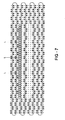
- the lead-in edge is knit using a "bind-off" stitch, as illustrated in Figure 7 with the interlinked knit stitch loops (L). Accordingly, the yarn or yarns forming the openings 22, 122 do not have loose free ends that would be prone to unraveling. Accordingly, the finished sleeve 10, 110 exhibits a long and useful life.
- the knitting can be performed to provide the openings 22, 122 of any suitable length and any suitable shape, such as generally round, oval, square or rectangular, by using a knit stitch pattern, by way of example and without limitation, as shown in Figure 7 .
Landscapes
- Engineering & Computer Science (AREA)
- General Engineering & Computer Science (AREA)
- Mechanical Engineering (AREA)
- Textile Engineering (AREA)
- Chemical & Material Sciences (AREA)
- Combustion & Propulsion (AREA)
- Knitting Of Fabric (AREA)
- Braiding, Manufacturing Of Bobbin-Net Or Lace, And Manufacturing Of Nets By Knotting (AREA)
- Exhaust Silencers (AREA)
- Thermal Insulation (AREA)
Description
- This invention relates generally to sleeves for protecting elongate members and more particularly to knit tubular protection sleeves.
- Knit tubular sleeves that provide protection from external elements and that provide a barrier to heat radiation from elongate members, such as exhaust pipes, wires and tubing, contained within the sleeves, are known. The sleeves are commonly knit from abrasion resistant, heat resistant, or fire retardant yarns to withstand relatively high temperatures and to allow portions of the sleeve to expand radially. The sleeves are commonly constructed having a continuous, closed tubular wall, such that the sleeves must be slid in sock-like fashion over the item being protected. Given the closed tubular wall construction, sometimes multiple sleeves are used in combination with one another to accommodate protrusions, e.g., sensors, or members branching from the item being protected, wherein adjacent ends of the sleeves are fastened to one another on opposite sides of the respective obstacle. This complicates the assembly process and adds labor/component cost. Otherwise, to avoid using multiple sleeves, some sleeves have an opening formed in the closed wall to accommodate the respective protrusion and/or member branching from the item being protected, or to facilitate locating the sleeve in a stationary position relative to a protrusion from the item being protected. In order to form the opening, or in some cases multiple openings, the closed wall must be slit, thereby resulting in frayed, loose ends of the yarns forming the closed wall. This generally results in unraveling of the yarns forming the sleeve, thereby reducing its ability to perform as intended and reducing its useful life.
- As such, to reduce the risk of degrading the usefulness and life of the closed wall sleeve, it is known to form openings in secondary cutting and sewing operations. In the secondary operations, the cut edges forming the opening are sewn to reduce the likelihood of their unraveling. Unfortunately, these secondary operations add cost to the manufacturing process. In addition, the sewn edges provide a potential origin for future unraveling, should the stitches come loose or broken during use.
- In addition, sometimes multiple closed wall portions of a sleeve or sleeves are overlapped with one another to form a multilayered sleeve to minimize the heat radiation outwardly from the item covered by the sleeve. Although this can be effective in reducing heat from radiating outwardly from the sleeve(s), it also retains the heat next to the covered item, thereby impacting its ability to be cooled. As such, it would be desirable to have a sleeve capable of both preventing heat from radiating outwardly in selected areas, while also being able to expel heat from the covered item in other areas to allow the item to be cooled.
- Knit sleeves manufactured in accordance with the present invention, among other things, overcome or greatly minimize any limitations of the known sleeves described above.
-
US 1,786,862 discloses a knitted stocking having an opening to accommodate the heel of a wearer integrally knitted in, said opening optionally being divided into two by a strap extending substantially parallel to a longitudinal axis of the stocking.US 4,961,418 discloses knitted fabric sleeve-like appliances for wrapping hand, elbow region, ankle region and knee region of a user, respectively and each formed with an opening for protrusion of thumb, elbow, heel and knee of the user. - The invention provides a sleeve for protecting elongate members and for inhibiting heat radiation outwardly from at least a portion thereof as specified in claim 1.
- The sleeve may have at least one elongate flap knit from the yarn or yarns, wherein the flap is foldable to abut at least a portion of the wall to provide a multilayered wall.
- The wall of the sleeve may be knit having a first knit stitch pattern and the flap may be knit having a second knit stitch pattern, the first knit stitch pattern being different from the second knit stitch pattern.
- A method of constructing a sleeve for protecting an elongate member received therein and for providing a thermal barrier to heat radiation is also provided as specified in claim 9.
- The method preferably includes weft knitting the sleeve on a flat bed knitting machine.
- The method may include knitting at least one elongate flap knit with the one or more yarns, with the flap being foldable to abut at least a portion of the wall to provide a multilayered wall.
- These and other features and advantages of a knit thermal sleeve constructed in accordance with the present invention will become more readily appreciated when considered in connection with the following detailed description of presently preferred embodiments and best mode, appended claims and accompanying drawings, in which:
-
Figure 1 is a schematic perspective view of a thermal sleeve constructed according to one embodiment of the invention shown assembled on an exhaust pipe; -
Figure 2 is a schematic perspective side view of a thermal sleeve constructed according to another embodiment of the invention shown in an unfolded state; -
Figure 3 is a schematic perspective view of the thermal sleeve ofFigure 2 shown in a reverse folded state; -
Figure 4 is a schematic perspective side view of a thermal sleeve constructed in accordance with another embodiment of the invention shown in an unfolded state; -
Figure 5 is a schematic perspective view of the thermal sleeve ofFigure 4 shown in a reverse folded state; -
Figure 6 is a schematic perspective view of a thermal sleeve constructed according to another embodiment of the invention shown assembled on an exhaust pipe; and -
Figure 7 is a portion of a knit stitch pattern for knitting an integral vent opening in a wall of a thermal sleeve according to one embodiment of the invention. - Referring in more detail to the drawings,
Figure 1 illustrates a knitthermal sleeve 10 constructed according to one embodiment of the invention for protecting heat generating elongate members, such as anexhaust pipe 11, for example. Thesleeve 10 has an elongate body, shown generally at 12, having awall 14 extending along alongitudinal axis 16, shown here as conforming to a bend in thepipe 11, between finish knitopposite ends sleeve 10. Thesleeve 10 has at least one, and represented here, by way of example and without limitation, as a plurality of thermal vent openings, referred to hereafter asopenings 22, wherein theopenings 22 are knit in the same continuous knitting operation used to knit thebody 12. Theopenings 22 can be knit having any size and shape using a predetermined series of needle and stitch transfers, as desired, to provide the desired amount of heat radiation outwardly from thesleeve 10. As such, thesleeve 10 can be constructed having thewall 14 suitably sized and positioned on thepipe 11 to provide a thermal barrier to heat radiation radially outwardly from thewall 14, while theopenings 22 can also be suitably sized and configured to provide an intended path promoting heat radiation radially outwardly through theopenings 22. Thus, nearby objects, such as temperature sensitive sensors, for example, or other temperature sensitive components can be protected from heat radiation by orienting thewall 14 between thepipe 11 and the component, while theopenings 22 can be oriented to direct the heat radially outwardly and away from the component. Accordingly, thesleeve 10 provides a thermal barrier in the region of thewall 14 and a thermal flow path in the region of theopenings 22. In addition, the ability to knit theopenings 22 concurrently with thewall 14 in a single knitting operation negates the necessity to perform secondary operations to form theopenings 22. Further, eachopening 22 has aperiphery 24 formed with continuous, uncut yarn or yarns, and thus, the yarn or yarns forming therespective opening 22 does not unravel, thereby providing thesleeve 10 with a long and useful life. Further yet, with theknit sleeve 10 being directly disposed over thepipe 11 in close abutment therewith, a low clearance heat barrier is provided, and in addition, with thewall 14 being formed of interlinked knit stitches, thewall 14 is able to be readily contoured to expand and contract as necessary to conform to the contour of thepipe 11. - The
wall 14 is knit from one or more yarns interlinked with one another by a plurality of knit stitches. The yarn or yarns, referred to hereafter simply as yarns unless otherwise specified, can be provided having any suitable characteristics and of any suitable material, such as monofilaments and/or multifilaments of any suitable Tex and material, including fire resistant and/or fire retardant (FR) yarns. If high temperature ratings are desired along with FR capabilities, then some presently preferred yarn materials include basalt, m-Aramid (Nomex, Conex, Kermel), p-aramid (Kevlar, Twaron, Technora), PE1 (Ultem), PPS, and PEEK, for example. Further, the yarns can be knit in any suitable stitch and pattern in discrete areas of thesleeve 10. For example, one portion of thewall 14 could be knit with one type of yarn in one knit stitch pattern, and another discrete portion of thewall 14 can be knit with another type of yarn having another knit stitch pattern. As such, a multitude of configurations and performance characteristics are possible, depending on the types of yarns and knit stitch patterns used in constructing thesleeve 10. - As shown schematically in
Figure 2 , asleeve 10 constructed in accordance with another presently preferred embodiment, wherein the same reference numerals are used to indicate similar features as identified inFigure 1 , can be constructed with thewall 14 having multiple thermal wall layers, with one layer being configured as aninner layer 26 for abutment with thepipe 11, and the other layer being configured as anouter layer 28. Theinner layer 26 is formed by a reverse folded elongate flap 30 (shown reverse folded inFigure 3 ). Theflap 30 is knit from at least some of the same yarns used to knit theouter layer 28 of thewall 14, and is shown here as being formed as a continuous knit extension of theouter layer 28 and extending from one of theends 18 of the finishedsleeve 10. Theflap 30 can be knit having any suitable length to allow it to be reverse folded to abut aninner surface 32 of theouter layer 28 of thewall 14. Theflap 30, thus, can be formed having substantially the same length as theouter layer 28, thereby providing thesleeve 10 with a full length dual thermal protective layers extending the full length of thesleeve 10. However, it should be recognized that theflap 30 could be constructed to extend less than the full length of thesleeve 10, if desired. - The
outer layer 28 of thewall 14 and theinner layer 26 of thewall 14 can be knit having different stitch patterns to provide the thermal protection desired. For example, theouter layer 28 can be knit having a first knit stitch pattern, such as a jersey or double jersey knit stitch pattern, while theinner layer 26 can be knit having a second knit stitch pattem, such as a rib knit stitch pattern (2X2 or 2X3, for example). With theouter layer 28 having a more dense knit stitch pattern, it provides an increased barrier to thermal radiation, while the less dense knit stitch pattern of theinner layer 26 provides an increased heat retention capacity, given theinner layer 26 has an increased porosity relative to theouter layer 28. Accordingly, heat is retained within thewall 14 and inhibited from radiating outwardly from thewall 14. - The
wall 14 can be constructed to span a portion of the circumference of thesleeve 10, or the entire circumference of thesleeve 10, with the exception of the area occupied by the opening oropenings 22. As shown inFigures 1-3 , thewall 14 spans a portion of the circumference, and is represented as extending between about 25-45 degrees, by way of example and without limitation. Thewall 14 has opposite side edges orfree edges longitudinal axis 16, wherein thefree edges opening 22, such that thefree edges opening 22. As such, the size of theopening 22 determines the length of thefree edges - The
sleeve 10 has a plurality of strap portions extending substantially transverse to thelongitudinal axis 16. A pair ofstrap portions 38 are represented as extending to theends ends inner strap portions 40 are shown spaced inwardly from theend strap portions 38. Theinner strap portions 40 extend continuously between theopposite edges openings 22. As such, the number ofopenings 22 diametrically opposite thewall 14 can be increased or decreased by varying the number ofstrap portions 40 knit continuously between theopposite edges wall 14. Of course, theinner strap portions 40 could be eliminated to provide asingle opening 22 bounded by theopposite edges Figure 6 . Each of thestrap portions wall 14, and thus, thestrap portions wall 14. The width of thestrap portions sleeve 10 can be varied, such that theopenings 22 can be increased or decreased in axial length, depending on the amount of heat radiation desired. - As mentioned above with regard to the
wall 14 and thestrap portions openings 22 can be knit along the length of thesleeve 10, from a single opening to a plurality of openings. Regardless of the size and number, theopenings 22 are bound by uncut yarns forming the wall edges 34, 36 and thestrap portions openings 22 can occupy between about 5 to 95 percent of the length of the sleeve, and the width of the opening oropenings 22 can extend as great as 10-320 degrees circumferentially about theaxis 16, and more preferably between about 45-270 degrees, depending on the size of thewall 14 desired to inhibit heat radiation and the sized of the openings desired to promote heat radiation. - As shown in
Figure 4 , wherein the same reference numerals used above offset by a factor of 100 identify similar features as above, asleeve 110 constructed in accordance with another embodiment is illustrated. Thesleeve 110 is generally the same as thesleeve 10, however, awall 114, rather than having dual layers, has three separate layers to further inhibit heat radiation outwardly from thewall 114. In order to form the threelayered wall 114, a pair offlap portions 130, 130' extend fromopposite ends outer layer 128 the 114. One of theflaps 130 is reverse folded to abut aninner surface 132 of theouter layer 128, and the other flap 130' is then reverse folded to abut an inner surface of theflap 130. Accordingly, the first reverse foldedflap 130 is sandwiched between theouter layer 128 the second reverse folded flap 130'. As described above in relation to thesleeve 10, theflaps 130, 130' can be knit having a different knit stitch and density than theouter layer 128, and further, they can be knit having a different knit stitch and density from one another. As such, theouter layer 128 can be knit having a tight knit stitch density to provide a thermal barrier to heat radiation, such as by using a jersey or double jersey knit stitch, for example. Thefirst flap 130, which forms an intermediate layer, can be knit having a looser knit stitch than theouter layer 128, such as by using a rib knit stitch, such as a 2X2 knit stitch, for example. Then, the second flap 130', which forms the inner most layer, can be knit having a different, and possibly looser knit stitch than theintermediate layer 130, such as a 2X3 knit stitch, for example. With the first andsecond flaps 130, 130' having different rib knit stitch patterns, the stitches are inhibited from nesting with one another, thereby providing more loft or air between thelayers 130, 130'. As such, the thermal insulation is enhanced by providing a built-in heat sink within thelayers 130, 130'. Otherwise, thesleeve 110 can be constructed generally the same as described above, including varying the number ofstraps portions sleeve 110, thereby varying the number ofopenings 122 formed within thesleeve 110. - In constructing the
sleeve sleeve vent openings knit strap portions wall openings openings openings Figure 7 with the interlinked knit stitch loops (L). Accordingly, the yarn or yarns forming theopenings finished sleeve openings Figure 7 . - Obviously, many modifications and variations of the present invention are possible in light of the above teachings. It is, therefore, to be understood that within the scope of the appended claims, the invention may be practiced otherwise than as specifically described.
Claims (13)
- A sleeve (10;110) for protecting elongate members (11) and for inhibiting heat radiation outwardly from at least a portion of the sleeve, comprising:an elongate body (12) having a wall (14; 114) extending along a longitudinal axis (16) of said sleeve (10;110) between opposite ends (18, 20; 118; 120) of said sleeve, said body (12) being constructed from one or more yarns interlinked with one another by a plurality of knit stitches; andat least one opening (22; 122) integrally knit in said body (12) between said opposite ends and diametrically opposite said wall (14; 114), said wall providing a thermal barrier to heat radiation radially outwardly from said wall and said opening (22; 122) providing a path promoting heat radiation radially outwardly from said opening, characterised in that said body (12) has a plurality of strap portions (38, 40: 138, 140) extending substantially transverse to said longitudinal axis (16) and said wall (14; 114) has opposite free edges (34, 36; 134, 136) substantially parallel to said longitudinal axis, said at least one opening (22; 122) being bounded peripherally by said strap portions (38, 40; 138, 140) and said opposite free edges.
- A sleeve according to claim 1 wherein said sleeve (10; 110) has a plurality of said openings (22; 122) diametrically opposite said wall (14; 114).
- A sleeve according to claim 1 or claim 2 wherein said at least one opening (22; 122) is bounded by uncut ones of said one or more yarns.
- A sleeve according to any preceding claim wherein said at least one opening (22; 122) extends axially at least 25 percent of a length between said ends (18, 20; 118; 120).
- A sleeve according to any preceding claim further comprising at least one elongate flap (30; 130, 130') knit from at least some of said one or more yarns, said at least one flap being foldable to abut at least a portion of said wall (14; 114) to provide said wall as a multilayered wall.
- A sleeve according to claim 5 wherein said at least one flap 30; 130, 130) is knit to extend from at least one of said opposite ends (18, 20; 118, 120).
- A sleeve according to claim 5 or 6 wherein said wall (14, 114) is knit having a first knit stitch pattern and said flap (30; 130, 130') is knit having a second knit stitch pattern, said first knit stitch pattern being different from said second knit stitch pattern.
- A sleeve according to claim 5 wherein said at least one elongate flap includes a flap (130, 130') extending from each of said opposite ends (118, 120).
- A method of constructing a sleeve (10;110) for protecting an elongate member (11) received therein and for inhibiting heat radiation outwardly from at least a portion of the sleeve, comprising:providing a knitting machine;knitting one or more yarns with one another to form an elongate body (12) having an insulating wall (14; 114) extending between opposite ends (18, 20; 118, 120) of the sleeve with the insulating wall being configured to prevent heat from radiating through the wall; andknitting at least one opening (22; 122) concurrently with the wall (14; 114) with the opening being configured diametrically opposite the wall and being sized to promote heat radiation through the opening, characterised by knitting the wall (14; 114) having a pair of free edges (34, 36; 134, 136) extending along a longitudinal axis (16) of the sleeve (10;110) and knitting a plurality of strap portions (38, 40; 138, 140) substantially transverse to said longitudinal axis (16) with at least some of the one or more yarns concurrently with the wall and bounding the at least one opening (22; 122) peripherally by the strap portions and the free edges.
- A method according to claim 9 further including weft knitting the body on a flat bed knitting machine.
- A method according to claim 9 or 10 further including knitting at least one elongate flap (30; 130, 130') with the one or more yarns, with the flap being foldable to abut at least a portion of the wall (14; 114) to provide the wall as a multilayered wall.
- A method according to claim 11 further including knitting the at least one flap (30; 130, 130') to extend from at least one of the opposite ends (18, 20; 118, 120) of the wall (14; 114).
- A method according to claim 11 or 12 further including knitting the wall (14; 114) using a first knit stitch pattern and knitting the or each flap (30; 130, 130') with a second knit stitch pattern that is different from the first knit stitch pattern.
Applications Claiming Priority (3)
| Application Number | Priority Date | Filing Date | Title |
|---|---|---|---|
| US95749407P | 2007-08-23 | 2007-08-23 | |
| US12/196,715 US7874184B2 (en) | 2007-08-23 | 2008-08-22 | Thermal protection sleeve with knit thermal protection features and method of construction thereof |
| PCT/US2008/074145 WO2009026578A1 (en) | 2007-08-23 | 2008-08-25 | Thermal protection sleeve with knit thermal protection features and method of construction thereof |
Publications (3)
| Publication Number | Publication Date |
|---|---|
| EP2185848A1 EP2185848A1 (en) | 2010-05-19 |
| EP2185848A4 EP2185848A4 (en) | 2014-05-14 |
| EP2185848B1 true EP2185848B1 (en) | 2015-03-11 |
Family
ID=40378715
Family Applications (1)
| Application Number | Title | Priority Date | Filing Date |
|---|---|---|---|
| EP08798576.8A Active EP2185848B1 (en) | 2007-08-23 | 2008-08-25 | Thermal protection sleeve with knit thermal protection features and method of construction thereof |
Country Status (6)
| Country | Link |
|---|---|
| US (1) | US7874184B2 (en) |
| EP (1) | EP2185848B1 (en) |
| JP (1) | JP5550117B2 (en) |
| KR (1) | KR101504980B1 (en) |
| CN (1) | CN101821540B (en) |
| WO (1) | WO2009026578A1 (en) |
Cited By (1)
| Publication number | Priority date | Publication date | Assignee | Title |
|---|---|---|---|---|
| US20240110659A1 (en) * | 2022-09-30 | 2024-04-04 | Federal-Mogul Powertrain Llc | Knit tubular thermal sleeve with wrappable cover and method of construction thereof |
Families Citing this family (19)
| Publication number | Priority date | Publication date | Assignee | Title |
|---|---|---|---|---|
| US8718694B2 (en) | 2007-12-07 | 2014-05-06 | Interdigital Patent Holdings, Inc. | Method and apparatus of signaling and procedure to support uplink power level determination |
| DE102008055480A1 (en) * | 2008-02-15 | 2009-08-20 | Contitech Mgw Gmbh | Flexible hose for high pressures and temperatures, in particular charge air or cooling water hose |
| EP2470366A4 (en) * | 2009-08-27 | 2016-04-13 | Whitford Corp | Method for improving impact damage resistance to textile articles, and articles made therefrom |
| JP2013544341A (en) * | 2010-09-30 | 2013-12-12 | フェデラル−モーグル パワートレイン インコーポレイテッド | Knitted sleeve with a knitted barrier extension having a barrier therein and method of construction thereof |
| CN103620111B (en) | 2011-06-14 | 2015-10-21 | 费德罗-莫格尔动力系公司 | A kind of coated textile sleeve and building method thereof |
| JP5782316B2 (en) * | 2011-07-12 | 2015-09-24 | ニチアス株式会社 | Piping cover, piping structure and vehicle |
| DE112013000141A5 (en) * | 2012-04-19 | 2014-06-26 | Buchen Umweltservice Gmbh | High pressure hose for a cleaning device and cleaning device |
| EP2671988A3 (en) * | 2012-06-06 | 2015-07-01 | E. I. du Pont de Nemours and Company | Knit fabric and an article comprising same |
| US9913415B2 (en) | 2013-03-13 | 2018-03-06 | Federal-Mogul Powertrain Llc | EMI shielding textile fabric, wrappable sleeve constructed therefrom and method of construction thereof |
| US9416469B2 (en) | 2014-05-21 | 2016-08-16 | Federal-Mogul Powertrain, Inc. | Flexible, abrasion resistant woven textile sleeve and method of construction thereof |
| USD749822S1 (en) * | 2014-10-27 | 2016-02-23 | Hugh Rodgers Poole, Jr. | Arm chaps |
| US9863070B2 (en) * | 2014-12-08 | 2018-01-09 | Federal-Mogul Powertrain Llc | Tubular protective sleeve with curl resistant knit ends and method of construction thereof |
| US10982355B2 (en) | 2016-07-25 | 2021-04-20 | Federal-Mogul Powertrain Llc | Knit tubular protective sleeve and method of construction thereof |
| US11305508B2 (en) | 2018-01-10 | 2022-04-19 | Federal-Mogul Powertrain Llc | Impact resistant, tubular textile sleeve and method of construction thereof |
| US20200003355A1 (en) * | 2018-06-28 | 2020-01-02 | Contitech Techno-Chemie Gmbh | Abrasion resistant patch for elastomeric hoses |
| EP3947796B1 (en) * | 2019-03-26 | 2024-06-19 | Federal-Mogul Powertrain LLC | Flexible, abrasion resistant, woven sleeve and method of construction thereof |
| JP7829578B2 (en) * | 2020-12-08 | 2026-03-13 | システムズ・プロテクション・グループ・ユー・エス・リミテッド・ライアビリティ・カンパニー | Location-locatable protective sleeve and method for constructing the same |
| US11851010B2 (en) | 2020-12-08 | 2023-12-26 | Federal-Mogul Powertrain Llc | Protective, locatable sleeve and method of construction thereof |
| US20250277329A1 (en) * | 2024-02-29 | 2025-09-04 | George GEHRING | Modular Attachment System Textile with Integrally Knit Slits and Manufacturing Method Thereof |
Family Cites Families (24)
| Publication number | Priority date | Publication date | Assignee | Title |
|---|---|---|---|---|
| US1786862A (en) * | 1927-04-11 | 1930-12-30 | Francisque Damon | Varicose stocking |
| FR2041278A5 (en) * | 1969-04-18 | 1971-01-29 | Syntexill | |
| JPS4726355U (en) * | 1971-04-14 | 1972-11-25 | ||
| JPS5424356A (en) * | 1977-07-25 | 1979-02-23 | Toyota Motor Corp | Nonvibratory heat shield |
| US4961418A (en) * | 1987-03-26 | 1990-10-09 | Mclaurin Smith Mark | Heat retaining fabric and physical therapy appliances |
| US4967419A (en) * | 1989-10-13 | 1990-11-06 | Elliott Grady N | Arm protector |
| US5413149A (en) * | 1991-11-05 | 1995-05-09 | The Bentley-Harris Manufacturing Company | Shaped fabric products and methods of making same |
| US7200872B2 (en) * | 1994-10-05 | 2007-04-10 | Kathryn Gregory | Article of thermal clothing for covering the underlying area at the gap between a coat sleeve and a glove |
| JP3592393B2 (en) * | 1995-02-13 | 2004-11-24 | 芦森工業株式会社 | Underground pipe protection material |
| US5778702A (en) * | 1996-09-06 | 1998-07-14 | Wrightenberry; Jerry O. | Double ply sock and method of making same |
| US5675992A (en) * | 1996-09-09 | 1997-10-14 | Wrightenberry; Jerry O. | Double layer sock with attached liner and method for forming same |
| US6108820A (en) * | 1997-07-11 | 2000-08-29 | Bernhardt; Frederick | Double layer sock with low friction layer to layer interface |
| US6051291A (en) | 1997-07-18 | 2000-04-18 | Federal-Mogul Systems Protection Group, Inc. | Heat reflective sleeve with insulating air pocket |
| JP3417841B2 (en) | 1998-04-28 | 2003-06-16 | ニチアス株式会社 | Insulation sleeve for high heat piping |
| US6158051A (en) * | 1999-05-27 | 2000-12-12 | Belzidsky; Hugo | Protective sleeve |
| JP2001082679A (en) * | 1999-09-17 | 2001-03-30 | Tokai Rubber Ind Ltd | Hose with protector and protector |
| US6324698B1 (en) * | 1999-11-07 | 2001-12-04 | Carol A. Freeman | Split sock |
| AUPR053100A0 (en) * | 2000-10-05 | 2000-10-26 | Exago Pty Limited | Supply chain management system |
| FR2832487B1 (en) * | 2001-11-21 | 2004-02-13 | Fed Mogul Systems Prot Group | PROTECTIVE SHEATH FOR FLUID CIRCULATION TUBE |
| JP4428655B2 (en) * | 2002-06-20 | 2010-03-10 | フェデラル−モーグル パワートレイン インコーポレイテッド | Multi-layer insulation sleeve |
| US7076973B1 (en) * | 2005-01-28 | 2006-07-18 | Wigwam Mills, Inc. | Method and apparatus for making a sock having a looped tab |
| US8273429B2 (en) | 2006-01-19 | 2012-09-25 | Federal-Mogul World Wide, Inc. | Fabric for end fray resistance and protective sleeves formed therewith and methods of construction |
| ATE447095T1 (en) * | 2006-05-10 | 2009-11-15 | Metal Textiles Corp | INSULATING SLEEVE WITH WIRE MESH AND WIRE MESH |
| US7757517B2 (en) * | 2007-08-23 | 2010-07-20 | Federal-Mogul Powertrain, Inc. | Protective sleeve with knitted opening and method on construction |
-
2008
- 2008-08-22 US US12/196,715 patent/US7874184B2/en active Active
- 2008-08-25 JP JP2010522098A patent/JP5550117B2/en active Active
- 2008-08-25 EP EP08798576.8A patent/EP2185848B1/en active Active
- 2008-08-25 CN CN2008801115039A patent/CN101821540B/en active Active
- 2008-08-25 WO PCT/US2008/074145 patent/WO2009026578A1/en not_active Ceased
- 2008-08-25 KR KR1020107006122A patent/KR101504980B1/en active Active
Cited By (1)
| Publication number | Priority date | Publication date | Assignee | Title |
|---|---|---|---|---|
| US20240110659A1 (en) * | 2022-09-30 | 2024-04-04 | Federal-Mogul Powertrain Llc | Knit tubular thermal sleeve with wrappable cover and method of construction thereof |
Also Published As
| Publication number | Publication date |
|---|---|
| WO2009026578A1 (en) | 2009-02-26 |
| JP2010537141A (en) | 2010-12-02 |
| EP2185848A4 (en) | 2014-05-14 |
| KR101504980B1 (en) | 2015-03-23 |
| CN101821540B (en) | 2011-12-28 |
| KR20100063070A (en) | 2010-06-10 |
| CN101821540A (en) | 2010-09-01 |
| US7874184B2 (en) | 2011-01-25 |
| JP5550117B2 (en) | 2014-07-16 |
| US20090049869A1 (en) | 2009-02-26 |
| EP2185848A1 (en) | 2010-05-19 |
Similar Documents
| Publication | Publication Date | Title |
|---|---|---|
| US7874184B2 (en) | Thermal protection sleeve with knit thermal protection features and method of construction thereof | |
| EP2185849B1 (en) | Method of construction of a protective sleeve with knitted opening | |
| EP2606168B1 (en) | Non-kinking self-wrapping woven sleeve and method of construction thereof | |
| US8434333B2 (en) | Tri-layer knit fabric, thermal protective members formed therefrom and methods of construction thereof | |
| EP3108048B1 (en) | Non-kinking wrappable knit sleeve and method of construction thereof | |
| US9394636B2 (en) | Enhanced braided sleeve and method of construction thereof | |
| EP3488037B1 (en) | Knit tubular protective sleeve and method of construction thereof | |
| EP3368710B1 (en) | Self-wrapping, braided textile sleeve with self-sustaining expanded and contracted states and method of construction thereof | |
| CN103228973A (en) | Knit sleeve with knit barrier extension having a barrier therein and method of construction | |
| CA2490090A1 (en) | Multiple layer insulating sleeve | |
| JP6420307B2 (en) | Corrugated knit sleeve and its construction method | |
| WO2014123869A1 (en) | Enhanced braided sleeve and method of construction thereof | |
| EP3230506B1 (en) | Tubular protective sleeve with curl resistant knit ends, method of construction thereof and method of installing same | |
| US20240110659A1 (en) | Knit tubular thermal sleeve with wrappable cover and method of construction thereof |
Legal Events
| Date | Code | Title | Description |
|---|---|---|---|
| PUAI | Public reference made under article 153(3) epc to a published international application that has entered the european phase |
Free format text: ORIGINAL CODE: 0009012 |
|
| 17P | Request for examination filed |
Effective date: 20100303 |
|
| AK | Designated contracting states |
Kind code of ref document: A1 Designated state(s): AT BE BG CH CY CZ DE DK EE ES FI FR GB GR HR HU IE IS IT LI LT LU LV MC MT NL NO PL PT RO SE SI SK TR |
|
| AX | Request for extension of the european patent |
Extension state: AL BA MK RS |
|
| RIN1 | Information on inventor provided before grant (corrected) |
Inventor name: ZHANG, ZHONG, HAUI Inventor name: MALLOY, CASSIE, M. Inventor name: BACON, ELLEN |
|
| DAX | Request for extension of the european patent (deleted) | ||
| A4 | Supplementary search report drawn up and despatched |
Effective date: 20140410 |
|
| RIC1 | Information provided on ipc code assigned before grant |
Ipc: F16L 57/04 20060101ALI20140404BHEP Ipc: F01N 13/14 20100101ALI20140404BHEP Ipc: B32B 23/02 20060101ALI20140404BHEP Ipc: D04B 1/22 20060101ALI20140404BHEP Ipc: F16L 11/02 20060101AFI20140404BHEP Ipc: F16L 57/06 20060101ALI20140404BHEP |
|
| RIC1 | Information provided on ipc code assigned before grant |
Ipc: F01N 13/14 20100101ALI20140903BHEP Ipc: D04B 1/22 20060101ALI20140903BHEP Ipc: F16L 57/04 20060101ALI20140903BHEP Ipc: F16L 11/02 20060101AFI20140903BHEP Ipc: B32B 23/02 20060101ALI20140903BHEP Ipc: F16L 57/06 20060101ALI20140903BHEP |
|
| GRAP | Despatch of communication of intention to grant a patent |
Free format text: ORIGINAL CODE: EPIDOSNIGR1 |
|
| INTG | Intention to grant announced |
Effective date: 20141022 |
|
| GRAS | Grant fee paid |
Free format text: ORIGINAL CODE: EPIDOSNIGR3 |
|
| GRAA | (expected) grant |
Free format text: ORIGINAL CODE: 0009210 |
|
| AK | Designated contracting states |
Kind code of ref document: B1 Designated state(s): AT BE BG CH CY CZ DE DK EE ES FI FR GB GR HR HU IE IS IT LI LT LU LV MC MT NL NO PL PT RO SE SI SK TR |
|
| REG | Reference to a national code |
Ref country code: GB Ref legal event code: FG4D |
|
| REG | Reference to a national code |
Ref country code: CH Ref legal event code: EP |
|
| REG | Reference to a national code |
Ref country code: IE Ref legal event code: FG4D |
|
| REG | Reference to a national code |
Ref country code: AT Ref legal event code: REF Ref document number: 715546 Country of ref document: AT Kind code of ref document: T Effective date: 20150415 |
|
| REG | Reference to a national code |
Ref country code: DE Ref legal event code: R096 Ref document number: 602008037119 Country of ref document: DE Effective date: 20150423 |
|
| REG | Reference to a national code |
Ref country code: FR Ref legal event code: PLFP Year of fee payment: 8 |
|
| REG | Reference to a national code |
Ref country code: NL Ref legal event code: VDEP Effective date: 20150311 |
|
| REG | Reference to a national code |
Ref country code: NL Ref legal event code: VDEP Effective date: 20150311 |
|
| PG25 | Lapsed in a contracting state [announced via postgrant information from national office to epo] |
Ref country code: LT Free format text: LAPSE BECAUSE OF FAILURE TO SUBMIT A TRANSLATION OF THE DESCRIPTION OR TO PAY THE FEE WITHIN THE PRESCRIBED TIME-LIMIT Effective date: 20150311 Ref country code: ES Free format text: LAPSE BECAUSE OF FAILURE TO SUBMIT A TRANSLATION OF THE DESCRIPTION OR TO PAY THE FEE WITHIN THE PRESCRIBED TIME-LIMIT Effective date: 20150311 Ref country code: SE Free format text: LAPSE BECAUSE OF FAILURE TO SUBMIT A TRANSLATION OF THE DESCRIPTION OR TO PAY THE FEE WITHIN THE PRESCRIBED TIME-LIMIT Effective date: 20150311 Ref country code: FI Free format text: LAPSE BECAUSE OF FAILURE TO SUBMIT A TRANSLATION OF THE DESCRIPTION OR TO PAY THE FEE WITHIN THE PRESCRIBED TIME-LIMIT Effective date: 20150311 Ref country code: NO Free format text: LAPSE BECAUSE OF FAILURE TO SUBMIT A TRANSLATION OF THE DESCRIPTION OR TO PAY THE FEE WITHIN THE PRESCRIBED TIME-LIMIT Effective date: 20150611 Ref country code: HR Free format text: LAPSE BECAUSE OF FAILURE TO SUBMIT A TRANSLATION OF THE DESCRIPTION OR TO PAY THE FEE WITHIN THE PRESCRIBED TIME-LIMIT Effective date: 20150311 |
|
| REG | Reference to a national code |
Ref country code: AT Ref legal event code: MK05 Ref document number: 715546 Country of ref document: AT Kind code of ref document: T Effective date: 20150311 |
|
| REG | Reference to a national code |
Ref country code: LT Ref legal event code: MG4D |
|
| PG25 | Lapsed in a contracting state [announced via postgrant information from national office to epo] |
Ref country code: LV Free format text: LAPSE BECAUSE OF FAILURE TO SUBMIT A TRANSLATION OF THE DESCRIPTION OR TO PAY THE FEE WITHIN THE PRESCRIBED TIME-LIMIT Effective date: 20150311 Ref country code: GR Free format text: LAPSE BECAUSE OF FAILURE TO SUBMIT A TRANSLATION OF THE DESCRIPTION OR TO PAY THE FEE WITHIN THE PRESCRIBED TIME-LIMIT Effective date: 20150612 |
|
| PG25 | Lapsed in a contracting state [announced via postgrant information from national office to epo] |
Ref country code: NL Free format text: LAPSE BECAUSE OF FAILURE TO SUBMIT A TRANSLATION OF THE DESCRIPTION OR TO PAY THE FEE WITHIN THE PRESCRIBED TIME-LIMIT Effective date: 20150311 |
|
| PG25 | Lapsed in a contracting state [announced via postgrant information from national office to epo] |
Ref country code: EE Free format text: LAPSE BECAUSE OF FAILURE TO SUBMIT A TRANSLATION OF THE DESCRIPTION OR TO PAY THE FEE WITHIN THE PRESCRIBED TIME-LIMIT Effective date: 20150311 Ref country code: PT Free format text: LAPSE BECAUSE OF FAILURE TO SUBMIT A TRANSLATION OF THE DESCRIPTION OR TO PAY THE FEE WITHIN THE PRESCRIBED TIME-LIMIT Effective date: 20150713 Ref country code: SK Free format text: LAPSE BECAUSE OF FAILURE TO SUBMIT A TRANSLATION OF THE DESCRIPTION OR TO PAY THE FEE WITHIN THE PRESCRIBED TIME-LIMIT Effective date: 20150311 Ref country code: CZ Free format text: LAPSE BECAUSE OF FAILURE TO SUBMIT A TRANSLATION OF THE DESCRIPTION OR TO PAY THE FEE WITHIN THE PRESCRIBED TIME-LIMIT Effective date: 20150311 Ref country code: RO Free format text: LAPSE BECAUSE OF FAILURE TO SUBMIT A TRANSLATION OF THE DESCRIPTION OR TO PAY THE FEE WITHIN THE PRESCRIBED TIME-LIMIT Effective date: 20150311 |
|
| PG25 | Lapsed in a contracting state [announced via postgrant information from national office to epo] |
Ref country code: PL Free format text: LAPSE BECAUSE OF FAILURE TO SUBMIT A TRANSLATION OF THE DESCRIPTION OR TO PAY THE FEE WITHIN THE PRESCRIBED TIME-LIMIT Effective date: 20150311 Ref country code: IS Free format text: LAPSE BECAUSE OF FAILURE TO SUBMIT A TRANSLATION OF THE DESCRIPTION OR TO PAY THE FEE WITHIN THE PRESCRIBED TIME-LIMIT Effective date: 20150711 Ref country code: AT Free format text: LAPSE BECAUSE OF FAILURE TO SUBMIT A TRANSLATION OF THE DESCRIPTION OR TO PAY THE FEE WITHIN THE PRESCRIBED TIME-LIMIT Effective date: 20150311 |
|
| REG | Reference to a national code |
Ref country code: DE Ref legal event code: R097 Ref document number: 602008037119 Country of ref document: DE |
|
| PLBE | No opposition filed within time limit |
Free format text: ORIGINAL CODE: 0009261 |
|
| STAA | Information on the status of an ep patent application or granted ep patent |
Free format text: STATUS: NO OPPOSITION FILED WITHIN TIME LIMIT |
|
| PG25 | Lapsed in a contracting state [announced via postgrant information from national office to epo] |
Ref country code: DK Free format text: LAPSE BECAUSE OF FAILURE TO SUBMIT A TRANSLATION OF THE DESCRIPTION OR TO PAY THE FEE WITHIN THE PRESCRIBED TIME-LIMIT Effective date: 20150311 |
|
| 26N | No opposition filed |
Effective date: 20151214 |
|
| PG25 | Lapsed in a contracting state [announced via postgrant information from national office to epo] |
Ref country code: SI Free format text: LAPSE BECAUSE OF FAILURE TO SUBMIT A TRANSLATION OF THE DESCRIPTION OR TO PAY THE FEE WITHIN THE PRESCRIBED TIME-LIMIT Effective date: 20150311 |
|
| PG25 | Lapsed in a contracting state [announced via postgrant information from national office to epo] |
Ref country code: LU Free format text: LAPSE BECAUSE OF FAILURE TO SUBMIT A TRANSLATION OF THE DESCRIPTION OR TO PAY THE FEE WITHIN THE PRESCRIBED TIME-LIMIT Effective date: 20150825 Ref country code: MC Free format text: LAPSE BECAUSE OF FAILURE TO SUBMIT A TRANSLATION OF THE DESCRIPTION OR TO PAY THE FEE WITHIN THE PRESCRIBED TIME-LIMIT Effective date: 20150311 |
|
| REG | Reference to a national code |
Ref country code: CH Ref legal event code: PL |
|
| GBPC | Gb: european patent ceased through non-payment of renewal fee |
Effective date: 20150825 |
|
| PG25 | Lapsed in a contracting state [announced via postgrant information from national office to epo] |
Ref country code: LI Free format text: LAPSE BECAUSE OF NON-PAYMENT OF DUE FEES Effective date: 20150831 Ref country code: CH Free format text: LAPSE BECAUSE OF NON-PAYMENT OF DUE FEES Effective date: 20150831 |
|
| REG | Reference to a national code |
Ref country code: IE Ref legal event code: MM4A |
|
| REG | Reference to a national code |
Ref country code: FR Ref legal event code: PLFP Year of fee payment: 9 |
|
| PG25 | Lapsed in a contracting state [announced via postgrant information from national office to epo] |
Ref country code: IE Free format text: LAPSE BECAUSE OF NON-PAYMENT OF DUE FEES Effective date: 20150825 Ref country code: GB Free format text: LAPSE BECAUSE OF NON-PAYMENT OF DUE FEES Effective date: 20150825 |
|
| PG25 | Lapsed in a contracting state [announced via postgrant information from national office to epo] |
Ref country code: BE Free format text: LAPSE BECAUSE OF FAILURE TO SUBMIT A TRANSLATION OF THE DESCRIPTION OR TO PAY THE FEE WITHIN THE PRESCRIBED TIME-LIMIT Effective date: 20150311 |
|
| PG25 | Lapsed in a contracting state [announced via postgrant information from national office to epo] |
Ref country code: MT Free format text: LAPSE BECAUSE OF FAILURE TO SUBMIT A TRANSLATION OF THE DESCRIPTION OR TO PAY THE FEE WITHIN THE PRESCRIBED TIME-LIMIT Effective date: 20150311 |
|
| PG25 | Lapsed in a contracting state [announced via postgrant information from national office to epo] |
Ref country code: BG Free format text: LAPSE BECAUSE OF FAILURE TO SUBMIT A TRANSLATION OF THE DESCRIPTION OR TO PAY THE FEE WITHIN THE PRESCRIBED TIME-LIMIT Effective date: 20150311 Ref country code: HU Free format text: LAPSE BECAUSE OF FAILURE TO SUBMIT A TRANSLATION OF THE DESCRIPTION OR TO PAY THE FEE WITHIN THE PRESCRIBED TIME-LIMIT; INVALID AB INITIO Effective date: 20080825 |
|
| PG25 | Lapsed in a contracting state [announced via postgrant information from national office to epo] |
Ref country code: CY Free format text: LAPSE BECAUSE OF FAILURE TO SUBMIT A TRANSLATION OF THE DESCRIPTION OR TO PAY THE FEE WITHIN THE PRESCRIBED TIME-LIMIT Effective date: 20150311 |
|
| REG | Reference to a national code |
Ref country code: FR Ref legal event code: PLFP Year of fee payment: 10 |
|
| PG25 | Lapsed in a contracting state [announced via postgrant information from national office to epo] |
Ref country code: TR Free format text: LAPSE BECAUSE OF FAILURE TO SUBMIT A TRANSLATION OF THE DESCRIPTION OR TO PAY THE FEE WITHIN THE PRESCRIBED TIME-LIMIT Effective date: 20150311 |
|
| REG | Reference to a national code |
Ref country code: FR Ref legal event code: PLFP Year of fee payment: 11 |
|
| PGFP | Annual fee paid to national office [announced via postgrant information from national office to epo] |
Ref country code: NL Payment date: 20180824 Year of fee payment: 11 |
|
| PG25 | Lapsed in a contracting state [announced via postgrant information from national office to epo] |
Ref country code: IT Free format text: LAPSE BECAUSE OF NON-PAYMENT OF DUE FEES Effective date: 20190825 |
|
| P01 | Opt-out of the competence of the unified patent court (upc) registered |
Effective date: 20230528 |
|
| PGFP | Annual fee paid to national office [announced via postgrant information from national office to epo] |
Ref country code: DE Payment date: 20250724 Year of fee payment: 18 |
|
| PGFP | Annual fee paid to national office [announced via postgrant information from national office to epo] |
Ref country code: FR Payment date: 20250725 Year of fee payment: 18 |
|
| REG | Reference to a national code |
Ref country code: DE Ref legal event code: R081 Ref document number: 602008037119 Country of ref document: DE Owner name: SYSTEMS PROTECTION GROUP US LLC (N.D.GES.D. ST, US Free format text: FORMER OWNER: FEDERAL-MOGUL POWERTRAIN, INC., SOUTHFIELD, MICH., US |
|
| REG | Reference to a national code |
Ref country code: DE Ref legal event code: R082 Ref document number: 602008037119 Country of ref document: DE Representative=s name: PUSCHMANN BORCHERT KAISER KLETTNER PATENTANWAE, DE Ref country code: DE Ref legal event code: R082 Ref document number: 602008037119 Country of ref document: DE Representative=s name: PATCARE PATENTANWAELTE PARTNERSCHAFT MBB, DE |