EP2185767B1 - A washer/dryer - Google Patents
A washer/dryer Download PDFInfo
- Publication number
- EP2185767B1 EP2185767B1 EP08803254.5A EP08803254A EP2185767B1 EP 2185767 B1 EP2185767 B1 EP 2185767B1 EP 08803254 A EP08803254 A EP 08803254A EP 2185767 B1 EP2185767 B1 EP 2185767B1
- Authority
- EP
- European Patent Office
- Prior art keywords
- flow regulator
- chamber
- dryer
- washer
- water
- Prior art date
- Legal status (The legal status is an assumption and is not a legal conclusion. Google has not performed a legal analysis and makes no representation as to the accuracy of the status listed.)
- Active
Links
Images

Classifications
-
- D—TEXTILES; PAPER
- D06—TREATMENT OF TEXTILES OR THE LIKE; LAUNDERING; FLEXIBLE MATERIALS NOT OTHERWISE PROVIDED FOR
- D06F—LAUNDERING, DRYING, IRONING, PRESSING OR FOLDING TEXTILE ARTICLES
- D06F58/00—Domestic laundry dryers
- D06F58/20—General details of domestic laundry dryers
- D06F58/24—Condensing arrangements
Definitions
- the present invention relates to a washer/dryer that comprises a chamber wherein the water condensed during the drying process is collected.
- German Patent Document No DE10023230 a dryer is explained, comprising a tubular shaped flow regulator with a surface whereon water impacts initially during filling in and discharge being without holes, thus attenuating the turbulence of water and the surface facing thereof having holes thereon for allowing water to be filled in and discharged.
- the aim of the present invention is the realization of a washer/dryer wherein the water condensed during drying is easily filled in/discharged from the chamber collecting the condensate.
- the washer/dryer realized in order to attain the aim of the present invention, explicated in the first claim and the respective claims thereof, comprises a chamber wherein the water condensed during the drying process is collected, an orifice allowing water to enter into the chamber and a flow regulator disposed in this orifice for regulating water flow during entry/exit of water from the chamber, shaped approximately like a hyperboloid of one sheet, that is widening conically upwards and downwards from the center.
- the flow regulator is inserted into the chamber from the orifice situated thereon and positioned such that the upper end of the hyperboloid corresponds with the orifice.
- the height of the flow regulator is less than the height of the chamber. Therefore when the flow regulator is placed in position, a gap remains between the end of the bottom half (B) and the base of the chamber at least allowing water to pass.
- the water condensed and delivered to the chamber flows down from the walls of the flow regulator and is received into the chamber. In the meantime, the speed of water slows down and the turbulence is attenuated. Thus, water is prevented from spattering while being received into the chamber. Similarly, the turbulence formed while carrying the chamber to be emptied is attenuated by the water impacting the walls of the flow regulator and water is prevented from splashing out by reaching the orifice.
- the flow regulator comprises more than one hole, particularly at the upper half (T) for allowing passage of water.
- the holes are formed to be grater slot shaped by protrusion.
- a flange each is disposed on the end of the upper half (T) of the flow regulator and at the edges of the orifice, matching each other, for securing the flow regulator after placing in the orifice.
- the water condensed during the drying process is received into the chamber with a regular flow preventing spattering to other sections of the washer/dryer and causing damages. Similarly, carrying the chamber to the place of discharging and the discharging processes are performed safely and easily.
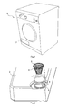
- Figure 1 - is the schematic view of a washer/dryer.
- Figure 2 - is the perspective view of a chamber and a flow regulator.
- Figure 3 - is the cross-sectional view of a flow regulator disposed in the chamber.
- Figure 4 - is the perspective view of the flow regulator.
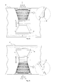
- Figure 5 - is the schematic view of the flow regulator and the chamber during filling in.
- Figure 6 - is the schematic view of the flow regulator and the chamber during discharging.
- the washer/dryer (1) comprises a chamber (2) wherein the water condensed during the drying process is collected, an orifice (3) allowing water entry into the chamber (2) and a flow regulator (4) that placed into the orifice (3), regulates water flow during the filling in/discharging processes ( Figures 1 and 2 ).
- the flow regulator (4) used in the washer/dryer (1) of the present invention is configured approximately as a hyperboloid of one sheet.
- the flow regulator (4) is disposed in the orifice (3) so that it remains in the chamber (2). Accordingly, water flows along the inner surface of the flow regulator (4) that serves almost like a funnel and is received into the chamber (2) with the turbulence attenuated. Moreover, the water spattering resulting from the turbulence formed during carrying of the chamber (2) by the user for the discharging process is prevented from reaching the orifice (3). The splashing water impacts on the walls of the flow regulator (4) and returns into the chamber (2) ( Figure 3 ).
- the hyperboloid shaped flow regulator (4) furthermore comprises more than one hole (5) formed on the upper half (T) for allowing passage of water.
- the hyperboloid shaped flow regulator (4) furthermore comprises more than one hole (5) formed on the upper half (T) for allowing passage of water.
- the holes (5) are formed by protrusion such that the water is allowed to flow into the chamber (2) during filling in and out of the chamber (2) during discharging.
- the protrude surfaces forming the holes (5) protrude outward from the flow regulator (4) and partially cover the hole (5).
- a flange (6) is formed, one each at the end of the upper half (T) of the flow regulator (4) and the edges of the orifice (3) mounted to each other by the bayonet method. Accordingly, the flow regulator (4) can be locked in place by turning after being placed in the orifice (3).
- a cylindrical passage is arranged between the lower half (B) of the flow regulator (4) and the upper half (T).
- the heights and diameters of the upper half (T) and the lower half (B) of the flow regulator (4) are different from each other.
- the flow regulator (4) used in the washer/dryer (1) of the present invention the water condensed during the drying process is received into the chamber (2) with a regular flow preventing spattering to unwanted sections.
- spattering of water during carrying the chamber (2) to the place of discharging and harming the user is prevented and the performing of discharging process is enabled easily and effectively.
Landscapes
- Engineering & Computer Science (AREA)
- Textile Engineering (AREA)
- Drying Of Solid Materials (AREA)
Description
- The present invention relates to a washer/dryer that comprises a chamber wherein the water condensed during the drying process is collected.
- In washer/dryers, the water condensed during the drying process is collected in a chamber and this chamber is discharged by the user after the drying process is completed. One of the problems encountered during these processes is the irregular flow of water while filling in the chamber and the spattering out of the water. The spattered water can reach unwanted places in the washer/dryer and cause malfunctions. Another problem is spattering of water while carrying to evacuate the chamber and during the evacuating process. Various embodiments are developed in the state of the art for solving these problems.
- In state of the art German Patent Document No
DE10023230 a dryer is explained, comprising a tubular shaped flow regulator with a surface whereon water impacts initially during filling in and discharge being without holes, thus attenuating the turbulence of water and the surface facing thereof having holes thereon for allowing water to be filled in and discharged. - In state of the art European Patent Application No
EP1743973 , a dryer is explained comprising a stepped shaped flow regulator emplaced at the orifice of the condensate receiver tank in order to prevent splashing and overflowing. -
DE-A-31,19,354 discloses a further prior art. - However even though these embodiments known in the state of the art are helpful in filling water into the chamber and delivering without splashing, it gives rise to difficulties in the discharging process, causing some amount of water to remain in the chamber.
- The aim of the present invention is the realization of a washer/dryer wherein the water condensed during drying is easily filled in/discharged from the chamber collecting the condensate.
- The washer/dryer realized in order to attain the aim of the present invention, explicated in the first claim and the respective claims thereof, comprises a chamber wherein the water condensed during the drying process is collected, an orifice allowing water to enter into the chamber and a flow regulator disposed in this orifice for regulating water flow during entry/exit of water from the chamber, shaped approximately like a hyperboloid of one sheet, that is widening conically upwards and downwards from the center.
- The flow regulator is inserted into the chamber from the orifice situated thereon and positioned such that the upper end of the hyperboloid corresponds with the orifice.
- The height of the flow regulator is less than the height of the chamber. Therefore when the flow regulator is placed in position, a gap remains between the end of the bottom half (B) and the base of the chamber at least allowing water to pass.
- The water condensed and delivered to the chamber flows down from the walls of the flow regulator and is received into the chamber. In the meantime, the speed of water slows down and the turbulence is attenuated. Thus, water is prevented from spattering while being received into the chamber. Similarly, the turbulence formed while carrying the chamber to be emptied is attenuated by the water impacting the walls of the flow regulator and water is prevented from splashing out by reaching the orifice.
- In an embodiment of the present invention, the flow regulator comprises more than one hole, particularly at the upper half (T) for allowing passage of water. In the preferred version of this embodiment the holes are formed to be grater slot shaped by protrusion.
- In an embodiment of the present invention, a flange each is disposed on the end of the upper half (T) of the flow regulator and at the edges of the orifice, matching each other, for securing the flow regulator after placing in the orifice.
- By means of the flow regulator used in the washer/dryer of the present invention, the water condensed during the drying process is received into the chamber with a regular flow preventing spattering to other sections of the washer/dryer and causing damages. Similarly, carrying the chamber to the place of discharging and the discharging processes are performed safely and easily.
- The washer/dryer realized in order to attain the aim of the present invention is illustrated in the attached figures, where:
-
Figure 1 - is the schematic view of a washer/dryer. -
Figure 2 - is the perspective view of a chamber and a flow regulator. -
Figure 3 - is the cross-sectional view of a flow regulator disposed in the chamber. -
Figure 4 - is the perspective view of the flow regulator. -
Figure 5 - is the schematic view of the flow regulator and the chamber during filling in. -
Figure 6 - is the schematic view of the flow regulator and the chamber during discharging. - The elements illustrated in the figures are numbered as follows:
- 1. Washer/dryer
- 2. Chamber
- 3. Orifice
- 4. Flow regulator
- 5. Hole
- 6. Flange
- The washer/dryer (1) comprises a chamber (2) wherein the water condensed during the drying process is collected, an orifice (3) allowing water entry into the chamber (2) and a flow regulator (4) that placed into the orifice (3), regulates water flow during the filling in/discharging processes (
Figures 1 and 2 ). - The flow regulator (4) used in the washer/dryer (1) of the present invention is configured approximately as a hyperboloid of one sheet. The flow regulator (4) is disposed in the orifice (3) so that it remains in the chamber (2). Accordingly, water flows along the inner surface of the flow regulator (4) that serves almost like a funnel and is received into the chamber (2) with the turbulence attenuated. Moreover, the water spattering resulting from the turbulence formed during carrying of the chamber (2) by the user for the discharging process is prevented from reaching the orifice (3). The splashing water impacts on the walls of the flow regulator (4) and returns into the chamber (2) (
Figure 3 ). - The hyperboloid shaped flow regulator (4) furthermore comprises more than one hole (5) formed on the upper half (T) for allowing passage of water. Thus, the water reaching the surface of the flow regulator (4) can be received into the chamber (2) easily and without spattering. On the other hand, when the chamber (2) is turned upside down during the discharging process, water will be easily discharged by entering both from the end of the hyperboloid upper half (B) and also from the holes (5) into the flow regulator (4) (
Figure 4 ). - In the preferred version of this embodiment, the holes (5) are formed by protrusion such that the water is allowed to flow into the chamber (2) during filling in and out of the chamber (2) during discharging. The protrude surfaces forming the holes (5) protrude outward from the flow regulator (4) and partially cover the hole (5). Thus, water can be effectively guided to the intended direction during both filling and discharging processes and flow can be performed regularly (
Figures 5 and 6 ). - In an embodiment of the present invention, a flange (6) is formed, one each at the end of the upper half (T) of the flow regulator (4) and the edges of the orifice (3) mounted to each other by the bayonet method. Accordingly, the flow regulator (4) can be locked in place by turning after being placed in the orifice (3).
- In an embodiment of the present invention, a cylindrical passage is arranged between the lower half (B) of the flow regulator (4) and the upper half (T). Thus, the turbulence of water received into the flow regulator (4) from the holes (5) on the upper half (T) can be decreased before pouring into the chamber (2).
- In another embodiment of the present invention, the heights and diameters of the upper half (T) and the lower half (B) of the flow regulator (4) are different from each other.
- By means of the flow regulator (4) used in the washer/dryer (1) of the present invention, the water condensed during the drying process is received into the chamber (2) with a regular flow preventing spattering to unwanted sections. On the other hand, spattering of water during carrying the chamber (2) to the place of discharging and harming the user is prevented and the performing of discharging process is enabled easily and effectively.
Claims (7)
- A washer/dryer (1) that comprises a chamber (2) wherein the water condensed during the drying process is collected, an orifice (3) allowing water entry into the chamber (2) and a flow regulator (4) that placed into the orifice (3), regulates water flow during filling in/discharging processes and characterized by the flow regulator (4) that is configured approximately as a hyperboloid of one sheet.
- A washer/dryer (1) as in Claim 1, characterized by the flow regulator (4) that is disposed in the orifice (3) so that it remains in the chamber (2) and serves as a funnel.
- A washer/dryer (1) as in Claim 1 or 2, characterized by the flow regulator (4) that comprises more than one hole (5) formed on the upper half (T) for allowing passage of water.
- A washer/dryer (1) as in Claim 3, characterized by the grater slot shaped holes (5) that are formed by protrusion.
- A washer/dryer (1) as in any one of the above claims, characterized by a flange (6) formed one each at the end of the upper half (T) of the flow regulator (4) and the edges of the orifice (3) mounted to each other by the bayonet method.
- A washer/dryer (1) as in any one of the above claims, characterized by the flow regulator (4) having a cylindrical passage arranged between the lower half (B) and the upper half (T).
- A washer/dryer (1) as in any one of the above claims, characterized by the flow regulator (4) wherein the heights and diameters of the upper half (T) and the lower half (B) are different from each other.
Applications Claiming Priority (2)
| Application Number | Priority Date | Filing Date | Title |
|---|---|---|---|
| TR200706033 | 2007-08-31 | ||
| PCT/EP2008/061187 WO2009027417A1 (en) | 2007-08-31 | 2008-08-27 | A washer/dryer |
Publications (2)
| Publication Number | Publication Date |
|---|---|
| EP2185767A1 EP2185767A1 (en) | 2010-05-19 |
| EP2185767B1 true EP2185767B1 (en) | 2013-10-02 |
Family
ID=40169470
Family Applications (1)
| Application Number | Title | Priority Date | Filing Date |
|---|---|---|---|
| EP08803254.5A Active EP2185767B1 (en) | 2007-08-31 | 2008-08-27 | A washer/dryer |
Country Status (3)
| Country | Link |
|---|---|
| EP (1) | EP2185767B1 (en) |
| ES (1) | ES2439956T3 (en) |
| WO (1) | WO2009027417A1 (en) |
Family Cites Families (1)
| Publication number | Priority date | Publication date | Assignee | Title |
|---|---|---|---|---|
| DE3119354C2 (en) * | 1981-05-15 | 1985-03-07 | Miele & Cie GmbH & Co, 4830 Gütersloh | Condensate collecting tank for a tumble dryer |
-
2008
- 2008-08-27 EP EP08803254.5A patent/EP2185767B1/en active Active
- 2008-08-27 WO PCT/EP2008/061187 patent/WO2009027417A1/en not_active Ceased
- 2008-08-27 ES ES08803254.5T patent/ES2439956T3/en active Active
Also Published As
| Publication number | Publication date |
|---|---|
| ES2439956T3 (en) | 2014-01-27 |
| EP2185767A1 (en) | 2010-05-19 |
| WO2009027417A1 (en) | 2009-03-05 |
Similar Documents
| Publication | Publication Date | Title |
|---|---|---|
| KR101292020B1 (en) | Boiler system for use with a steaming device | |
| NZ225490A (en) | Dry detergent dispenser with horizontal water jet solvation | |
| CN103221605A (en) | Lint filter for a laundry treatment device, laundry treatment device having an accommodation space for the lint filter, and filter insert | |
| CA2017165A1 (en) | Apparatus for preparing hot beverages in a microwave-oven | |
| CN100549533C (en) | heating cooker | |
| EP1887127A1 (en) | Laundry treating machine | |
| JP2018103085A (en) | Rice washing equipment | |
| EP2921585B1 (en) | A top-loading laundry washing machine and a laundry drum for such machine | |
| US8002147B2 (en) | Method and apparatus for a drip tray screen | |
| WO2005090867A1 (en) | Steam cooking apparatus | |
| WO2009027417A1 (en) | A washer/dryer | |
| JP7484698B2 (en) | Rice washing equipment | |
| CA2394106C (en) | Gas dryer | |
| EP2798118B1 (en) | A condensation type laundry dryer | |
| KR100820739B1 (en) | washer | |
| JP6290196B2 (en) | Steam iron with steam permeable screen | |
| FR2608414A1 (en) | Water supply installation for washing machines etc. | |
| KR101265029B1 (en) | Water discharging trap for a steam generating system using a laundry | |
| EP4019686B1 (en) | A laundry washer-dryer with improved operational safety | |
| JP3735520B2 (en) | Beverage dispenser | |
| JP5056140B2 (en) | coffee maker | |
| KR0184183B1 (en) | Condenser of Drum Washing Machine | |
| KR101043209B1 (en) | Cooking vessel steam discharge device | |
| JP5061702B2 (en) | coffee maker | |
| JP2002303451A (en) | Hot water storage tank |
Legal Events
| Date | Code | Title | Description |
|---|---|---|---|
| PUAI | Public reference made under article 153(3) epc to a published international application that has entered the european phase |
Free format text: ORIGINAL CODE: 0009012 |
|
| 17P | Request for examination filed |
Effective date: 20100316 |
|
| AK | Designated contracting states |
Kind code of ref document: A1 Designated state(s): AT BE BG CH CY CZ DE DK EE ES FI FR GB GR HR HU IE IS IT LI LT LU LV MC MT NL NO PL PT RO SE SI SK TR |
|
| AX | Request for extension of the european patent |
Extension state: AL BA MK RS |
|
| DAX | Request for extension of the european patent (deleted) | ||
| GRAP | Despatch of communication of intention to grant a patent |
Free format text: ORIGINAL CODE: EPIDOSNIGR1 |
|
| INTG | Intention to grant announced |
Effective date: 20130405 |
|
| GRAS | Grant fee paid |
Free format text: ORIGINAL CODE: EPIDOSNIGR3 |
|
| GRAA | (expected) grant |
Free format text: ORIGINAL CODE: 0009210 |
|
| AK | Designated contracting states |
Kind code of ref document: B1 Designated state(s): AT BE BG CH CY CZ DE DK EE ES FI FR GB GR HR HU IE IS IT LI LT LU LV MC MT NL NO PL PT RO SE SI SK TR |
|
| REG | Reference to a national code |
Ref country code: GB Ref legal event code: FG4D |
|
| REG | Reference to a national code |
Ref country code: AT Ref legal event code: REF Ref document number: 634693 Country of ref document: AT Kind code of ref document: T Effective date: 20131015 Ref country code: CH Ref legal event code: EP |
|
| REG | Reference to a national code |
Ref country code: IE Ref legal event code: FG4D |
|
| REG | Reference to a national code |
Ref country code: DE Ref legal event code: R096 Ref document number: 602008027929 Country of ref document: DE Effective date: 20131128 |
|
| REG | Reference to a national code |
Ref country code: ES Ref legal event code: FG2A Ref document number: 2439956 Country of ref document: ES Kind code of ref document: T3 Effective date: 20140127 |
|
| REG | Reference to a national code |
Ref country code: AT Ref legal event code: MK05 Ref document number: 634693 Country of ref document: AT Kind code of ref document: T Effective date: 20131002 |
|
| REG | Reference to a national code |
Ref country code: NL Ref legal event code: VDEP Effective date: 20131002 |
|
| PG25 | Lapsed in a contracting state [announced via postgrant information from national office to epo] |
Ref country code: SI Free format text: LAPSE BECAUSE OF FAILURE TO SUBMIT A TRANSLATION OF THE DESCRIPTION OR TO PAY THE FEE WITHIN THE PRESCRIBED TIME-LIMIT Effective date: 20131002 |
|
| REG | Reference to a national code |
Ref country code: LT Ref legal event code: MG4D |
|
| PG25 | Lapsed in a contracting state [announced via postgrant information from national office to epo] |
Ref country code: NL Free format text: LAPSE BECAUSE OF FAILURE TO SUBMIT A TRANSLATION OF THE DESCRIPTION OR TO PAY THE FEE WITHIN THE PRESCRIBED TIME-LIMIT Effective date: 20131002 Ref country code: CZ Free format text: LAPSE BECAUSE OF FAILURE TO SUBMIT A TRANSLATION OF THE DESCRIPTION OR TO PAY THE FEE WITHIN THE PRESCRIBED TIME-LIMIT Effective date: 20131002 Ref country code: LT Free format text: LAPSE BECAUSE OF FAILURE TO SUBMIT A TRANSLATION OF THE DESCRIPTION OR TO PAY THE FEE WITHIN THE PRESCRIBED TIME-LIMIT Effective date: 20131002 Ref country code: BE Free format text: LAPSE BECAUSE OF FAILURE TO SUBMIT A TRANSLATION OF THE DESCRIPTION OR TO PAY THE FEE WITHIN THE PRESCRIBED TIME-LIMIT Effective date: 20131002 Ref country code: FI Free format text: LAPSE BECAUSE OF FAILURE TO SUBMIT A TRANSLATION OF THE DESCRIPTION OR TO PAY THE FEE WITHIN THE PRESCRIBED TIME-LIMIT Effective date: 20131002 Ref country code: SE Free format text: LAPSE BECAUSE OF FAILURE TO SUBMIT A TRANSLATION OF THE DESCRIPTION OR TO PAY THE FEE WITHIN THE PRESCRIBED TIME-LIMIT Effective date: 20131002 Ref country code: HR Free format text: LAPSE BECAUSE OF FAILURE TO SUBMIT A TRANSLATION OF THE DESCRIPTION OR TO PAY THE FEE WITHIN THE PRESCRIBED TIME-LIMIT Effective date: 20131002 Ref country code: NO Free format text: LAPSE BECAUSE OF FAILURE TO SUBMIT A TRANSLATION OF THE DESCRIPTION OR TO PAY THE FEE WITHIN THE PRESCRIBED TIME-LIMIT Effective date: 20140102 Ref country code: IS Free format text: LAPSE BECAUSE OF FAILURE TO SUBMIT A TRANSLATION OF THE DESCRIPTION OR TO PAY THE FEE WITHIN THE PRESCRIBED TIME-LIMIT Effective date: 20140202 |
|
| PG25 | Lapsed in a contracting state [announced via postgrant information from national office to epo] |
Ref country code: LV Free format text: LAPSE BECAUSE OF FAILURE TO SUBMIT A TRANSLATION OF THE DESCRIPTION OR TO PAY THE FEE WITHIN THE PRESCRIBED TIME-LIMIT Effective date: 20131002 Ref country code: CY Free format text: LAPSE BECAUSE OF FAILURE TO SUBMIT A TRANSLATION OF THE DESCRIPTION OR TO PAY THE FEE WITHIN THE PRESCRIBED TIME-LIMIT Effective date: 20131002 Ref country code: PL Free format text: LAPSE BECAUSE OF FAILURE TO SUBMIT A TRANSLATION OF THE DESCRIPTION OR TO PAY THE FEE WITHIN THE PRESCRIBED TIME-LIMIT Effective date: 20131002 Ref country code: AT Free format text: LAPSE BECAUSE OF FAILURE TO SUBMIT A TRANSLATION OF THE DESCRIPTION OR TO PAY THE FEE WITHIN THE PRESCRIBED TIME-LIMIT Effective date: 20131002 |
|
| PG25 | Lapsed in a contracting state [announced via postgrant information from national office to epo] |
Ref country code: PT Free format text: LAPSE BECAUSE OF FAILURE TO SUBMIT A TRANSLATION OF THE DESCRIPTION OR TO PAY THE FEE WITHIN THE PRESCRIBED TIME-LIMIT Effective date: 20140203 |
|
| REG | Reference to a national code |
Ref country code: DE Ref legal event code: R097 Ref document number: 602008027929 Country of ref document: DE |
|
| PG25 | Lapsed in a contracting state [announced via postgrant information from national office to epo] |
Ref country code: EE Free format text: LAPSE BECAUSE OF FAILURE TO SUBMIT A TRANSLATION OF THE DESCRIPTION OR TO PAY THE FEE WITHIN THE PRESCRIBED TIME-LIMIT Effective date: 20131002 |
|
| PLBE | No opposition filed within time limit |
Free format text: ORIGINAL CODE: 0009261 |
|
| STAA | Information on the status of an ep patent application or granted ep patent |
Free format text: STATUS: NO OPPOSITION FILED WITHIN TIME LIMIT |
|
| PG25 | Lapsed in a contracting state [announced via postgrant information from national office to epo] |
Ref country code: RO Free format text: LAPSE BECAUSE OF FAILURE TO SUBMIT A TRANSLATION OF THE DESCRIPTION OR TO PAY THE FEE WITHIN THE PRESCRIBED TIME-LIMIT Effective date: 20131002 Ref country code: SK Free format text: LAPSE BECAUSE OF FAILURE TO SUBMIT A TRANSLATION OF THE DESCRIPTION OR TO PAY THE FEE WITHIN THE PRESCRIBED TIME-LIMIT Effective date: 20131002 |
|
| 26N | No opposition filed |
Effective date: 20140703 |
|
| PG25 | Lapsed in a contracting state [announced via postgrant information from national office to epo] |
Ref country code: DK Free format text: LAPSE BECAUSE OF FAILURE TO SUBMIT A TRANSLATION OF THE DESCRIPTION OR TO PAY THE FEE WITHIN THE PRESCRIBED TIME-LIMIT Effective date: 20131002 |
|
| REG | Reference to a national code |
Ref country code: DE Ref legal event code: R097 Ref document number: 602008027929 Country of ref document: DE Effective date: 20140703 |
|
| PG25 | Lapsed in a contracting state [announced via postgrant information from national office to epo] |
Ref country code: MC Free format text: LAPSE BECAUSE OF FAILURE TO SUBMIT A TRANSLATION OF THE DESCRIPTION OR TO PAY THE FEE WITHIN THE PRESCRIBED TIME-LIMIT Effective date: 20131002 Ref country code: LU Free format text: LAPSE BECAUSE OF FAILURE TO SUBMIT A TRANSLATION OF THE DESCRIPTION OR TO PAY THE FEE WITHIN THE PRESCRIBED TIME-LIMIT Effective date: 20140827 |
|
| REG | Reference to a national code |
Ref country code: CH Ref legal event code: PL |
|
| PG25 | Lapsed in a contracting state [announced via postgrant information from national office to epo] |
Ref country code: CH Free format text: LAPSE BECAUSE OF NON-PAYMENT OF DUE FEES Effective date: 20140831 Ref country code: LI Free format text: LAPSE BECAUSE OF NON-PAYMENT OF DUE FEES Effective date: 20140831 |
|
| REG | Reference to a national code |
Ref country code: IE Ref legal event code: MM4A |
|
| PG25 | Lapsed in a contracting state [announced via postgrant information from national office to epo] |
Ref country code: IE Free format text: LAPSE BECAUSE OF NON-PAYMENT OF DUE FEES Effective date: 20140827 |
|
| PG25 | Lapsed in a contracting state [announced via postgrant information from national office to epo] |
Ref country code: NO Free format text: LAPSE BECAUSE OF FAILURE TO SUBMIT A TRANSLATION OF THE DESCRIPTION OR TO PAY THE FEE WITHIN THE PRESCRIBED TIME-LIMIT Effective date: 20140101 |
|
| PG25 | Lapsed in a contracting state [announced via postgrant information from national office to epo] |
Ref country code: BG Free format text: LAPSE BECAUSE OF FAILURE TO SUBMIT A TRANSLATION OF THE DESCRIPTION OR TO PAY THE FEE WITHIN THE PRESCRIBED TIME-LIMIT Effective date: 20131002 |
|
| PG25 | Lapsed in a contracting state [announced via postgrant information from national office to epo] |
Ref country code: GR Free format text: LAPSE BECAUSE OF FAILURE TO SUBMIT A TRANSLATION OF THE DESCRIPTION OR TO PAY THE FEE WITHIN THE PRESCRIBED TIME-LIMIT Effective date: 20140103 Ref country code: MT Free format text: LAPSE BECAUSE OF FAILURE TO SUBMIT A TRANSLATION OF THE DESCRIPTION OR TO PAY THE FEE WITHIN THE PRESCRIBED TIME-LIMIT Effective date: 20131002 |
|
| PG25 | Lapsed in a contracting state [announced via postgrant information from national office to epo] |
Ref country code: HU Free format text: LAPSE BECAUSE OF FAILURE TO SUBMIT A TRANSLATION OF THE DESCRIPTION OR TO PAY THE FEE WITHIN THE PRESCRIBED TIME-LIMIT; INVALID AB INITIO Effective date: 20080827 |
|
| REG | Reference to a national code |
Ref country code: FR Ref legal event code: PLFP Year of fee payment: 9 |
|
| REG | Reference to a national code |
Ref country code: FR Ref legal event code: PLFP Year of fee payment: 10 |
|
| REG | Reference to a national code |
Ref country code: FR Ref legal event code: PLFP Year of fee payment: 11 |
|
| PGFP | Annual fee paid to national office [announced via postgrant information from national office to epo] |
Ref country code: IT Payment date: 20200828 Year of fee payment: 13 |
|
| PGFP | Annual fee paid to national office [announced via postgrant information from national office to epo] |
Ref country code: ES Payment date: 20201023 Year of fee payment: 13 |
|
| PG25 | Lapsed in a contracting state [announced via postgrant information from national office to epo] |
Ref country code: IT Free format text: LAPSE BECAUSE OF NON-PAYMENT OF DUE FEES Effective date: 20210827 |
|
| REG | Reference to a national code |
Ref country code: ES Ref legal event code: FD2A Effective date: 20221031 |
|
| PG25 | Lapsed in a contracting state [announced via postgrant information from national office to epo] |
Ref country code: ES Free format text: LAPSE BECAUSE OF NON-PAYMENT OF DUE FEES Effective date: 20210828 |
|
| PGFP | Annual fee paid to national office [announced via postgrant information from national office to epo] |
Ref country code: DE Payment date: 20250820 Year of fee payment: 18 |
|
| PGFP | Annual fee paid to national office [announced via postgrant information from national office to epo] |
Ref country code: TR Payment date: 20250825 Year of fee payment: 18 |
|
| PGFP | Annual fee paid to national office [announced via postgrant information from national office to epo] |
Ref country code: GB Payment date: 20250820 Year of fee payment: 18 |
|
| PGFP | Annual fee paid to national office [announced via postgrant information from national office to epo] |
Ref country code: FR Payment date: 20250829 Year of fee payment: 18 |