EP2185245B1 - Stowage box for breathing mask - Google Patents
Stowage box for breathing mask Download PDFInfo
- Publication number
- EP2185245B1 EP2185245B1 EP07826158A EP07826158A EP2185245B1 EP 2185245 B1 EP2185245 B1 EP 2185245B1 EP 07826158 A EP07826158 A EP 07826158A EP 07826158 A EP07826158 A EP 07826158A EP 2185245 B1 EP2185245 B1 EP 2185245B1
- Authority
- EP
- European Patent Office
- Prior art keywords
- mask
- breathing
- stowage box
- frame
- box
- Prior art date
- Legal status (The legal status is an assumption and is not a legal conclusion. Google has not performed a legal analysis and makes no representation as to the accuracy of the status listed.)
- Not-in-force
Links
Images


Classifications
-
- A—HUMAN NECESSITIES
- A62—LIFE-SAVING; FIRE-FIGHTING
- A62B—DEVICES, APPARATUS OR METHODS FOR LIFE-SAVING
- A62B25/00—Devices for storing or holding or carrying respiratory or breathing apparatus
- A62B25/005—Devices for storing or holding or carrying respiratory or breathing apparatus for high altitude
-
- B—PERFORMING OPERATIONS; TRANSPORTING
- B64—AIRCRAFT; AVIATION; COSMONAUTICS
- B64D—EQUIPMENT FOR FITTING IN OR TO AIRCRAFT; FLIGHT SUITS; PARACHUTES; ARRANGEMENTS OR MOUNTING OF POWER PLANTS OR PROPULSION TRANSMISSIONS IN AIRCRAFT
- B64D10/00—Flight suits
Definitions
- the invention relates to the field of stowage box for breathing mask.
- a protective mask is generally stored in a box called a stowage box located next to the crewmember's position.
- the stowage box comprises a frame forming a receptacle for the mask, itself having an open face of rectangular shape for inserting and extracting the mask, and at least two doors closing the open face of the frame, at least in part.
- the mask is extracted through the face that is closed by two doors that retain and/or protect the mask, each opening and closing about a respective hinge, the two hinges of the doors operating about two parallel hinge axes.
- the box is installed on the right or left of the seat of the pilot, the open face being generally the top side of the box.
- the stowage box comprises a pneumatic assembly able to close the feed of breathing gas of the breathing mask when the breathing mask is installed in the stowage box.
- the objective of the pneumatic assembly is to reduce or suppress the consumption of breathing gas when the mask is not in use. Therefore, the pneumatic assembly is connected to one of the doors of the box such that the feed of breathing gas is closed when the doors are closed and is open when the doors are open.
- patent application US 2004/0144384 discloses such a box.
- a stowage box for a breathing mask comprises:
- the pneumatic assembly is adapted to close the feed of breathing gas when the mask is inserted into the frame and to open the feed of breathing gas when the mask is extracted from the frame.
- the box is advantageously controlling the feed of breathable gas through the position of the mask and not though the position of a door as in the prior art. Therefore the space occupied by the box is less than the space occupied by a prior art box as no space is used by the doors.
- a stowage box 1 for a breathable mask (not represented) comprises a frame 3 forming a receptacle for the mask.
- the frame 3 comprises a substantially vertical side 5 which is used to fix the stowage box 1 onto a wall of the aircraft cabin and forms the bottom of the receptacle.
- the frame 3 further comprises sides 7, 9, 11, 13 forming a volume adapted to enclose the mask and an open face 15 for inserting or extracting the mask.
- a mortise 17 leads into the open face.
- a groove 18 is formed on the side 13, at the entry of the mortise 17.
- the groove 18 is linear and substantially vertical.
- a pneumatic assembly 19 is fixed at an end of the mortise 17 opposite to the open face 15.
- the pneumatic assembly 19 comprises a button 21, a first tube 23 coming from a breathing gas generator (not represented) and a second tube 25 connected to the breathing mask. So the breathing mask is fed in breathable gas from the breathing gas generator through the pneumatic assembly 19.
- the pneumatic assembly 19 further comprises, Figure 2 , a duct 27 in U-shape connecting the first tube 23 with the second tube 25.
- the button 21 is the proximal end of a sliding valve 29 having a substantially cylindrical form.
- the valve 29 slides into a tube 31 running on from the base of the U of the duct 27.
- the valve 29 comprises two O-rings 33, 35, one roughly in the middle of the valve 29 and one at the distal end of the valve 29, opposite of the button 21.
- the sliding valve 29 comprises also a collar 37.
- the tube 31 is screwed into a larger cylinder 39 leading into the duct 27.
- the rigid part 41 of the mask comprises a movable part 49, and a fixed part 51 having a striated surface.
- the moving part 49 comprises a lug 53, adapted to be inserted into the groove 18.
- the operation of the stowage box 1 is the following.
- the pilot maintains the breathing mask 43 by means of the two parts 49, 51 that the pilot pinches with the thumb and at least the forefinger.
- the movable part 49 is in an inwards position.
- the rigid part 41 slides along the side 13 and the mortise 17 guides the stand-outs 45 so that the breathing mask 43 is in position inside the stowage box 1.
- the stand-outs 45 having a L-shape, the border of the mortise 17 is inserted between the bottom of the rigid part 41 and the feet of the stand-outs 45.
- the pilot releases the movable part 49 so that the lug 53 is inserted into the groove 18 so that the breathing mask 43 is maintained in the stowage position by the stand-outs 45 and the lug 53.
- the rigid part 41 pushes the button 21 and, therefore, the valve 29 in a close position where the duct 27 is hermetically obstructed by the end of the valve and the O-ring 35.
- the pilot When the pilot needs the breathing mask 43, he pinches the movable part 49 as explained here above to move it inwards and disengage the lug 53 from the groove 18. Then, the pilot can extract the breathing mask 43 from the stowage box, releasing at the same time the valve 29.
- the breathing gas arrives into the duct 27 through the tube 23 at a pressure of at least 3 bars. Therefore the difference of pressure between the breathable gas and the cabin pressure is such that the valve 29 is pushed by the breathable gas and slides to an open position, Figure 5 .
- the O-ring 33 hermetically seals the connection between the valve 29 and the tube 31 to avoid any leakage of breathable gas.
- the collar 37 limits the movement of the valve 29 by butting against the tube 31 in the open position, and by butting against a shoulder of the duct in the close position.
- different means may be used to maintain the breathing mask in stowage position such as a strap crossing the open face and fixed by a hook and loop fastener.
- the groove 18 and its counterpart 53 are described on the right-hand side of the box. However, they may be positioned on the left-hand side or doubled on each side of the mask/box.
- the duct may have an L-shape with the tube 23 running on from the valve 29.
Description
- The invention relates to the field of stowage box for breathing mask.
- To ensure the safety of the passengers and crewmembers in case of a depressurization accident or the occurrence of smoke in the aircraft, aviation regulations require on board all airliners a safety oxygen supply circuit able to supply each passenger and crewmember with an oxygen flow rate function of the cabin altitude. Such oxygen is delivered to the crewmember or passenger, also known as end user, through a breathing mask.
- After a depressurization accident or upon the occurrence of smoke in the aircraft, the crewmembers must don their protective mask upon their face as quickly as possible (see f.i.
US 5 954 052 ). Indeed, the lack of oxygen at high altitude (hypoxia) or the toxic fumes can alter the crewmembers' abilities to proceed with any emergency measures that will ensure the safety of the passengers and the aircraft. - A protective mask is generally stored in a box called a stowage box located next to the crewmember's position. Generally, the stowage box comprises a frame forming a receptacle for the mask, itself having an open face of rectangular shape for inserting and extracting the mask, and at least two doors closing the open face of the frame, at least in part. The mask is extracted through the face that is closed by two doors that retain and/or protect the mask, each opening and closing about a respective hinge, the two hinges of the doors operating about two parallel hinge axes. The box is installed on the right or left of the seat of the pilot, the open face being generally the top side of the box. The stowage box comprises a pneumatic assembly able to close the feed of breathing gas of the breathing mask when the breathing mask is installed in the stowage box. The objective of the pneumatic assembly is to reduce or suppress the consumption of breathing gas when the mask is not in use. Therefore, the pneumatic assembly is connected to one of the doors of the box such that the feed of breathing gas is closed when the doors are closed and is open when the doors are open.
- For instance, patent application
US 2004/0144384 discloses such a box. - Problem with such a box is the occupied space in small aircraft. The known boxes are well suited for large aircraft, typically able to transport 100 passengers and more, in which the pilot cabin is large enough.
- However, in small passenger aircrafts, typically able to transport between 10 and 80 passengers, the pilot cabin is crowded by all the equipments used to control the aircraft. And there is no space available around the seats of the pilots to install a stowage box as known in the prior art.
- It would be advantageous to achieve a stowage box that can be installed inside a cabin of a small passenger aircraft but with the same functionality and safety as the box of the prior art, i.e. to allow the feed of breathable gas only when the mask is in use but always when the mask is in use.
- To better address one or more concerns, in a first aspect of the invention, a stowage box for a breathing mask comprises:
- ● a frame forming a receptacle for the mask, said frame having an open face for inserting and extracting the mask, and
- ● a pneumatic assembly to control the feed of breathing gas under pressure to the breathing mask.
- And the pneumatic assembly is adapted to close the feed of breathing gas when the mask is inserted into the frame and to open the feed of breathing gas when the mask is extracted from the frame.
- The box is advantageously controlling the feed of breathable gas through the position of the mask and not though the position of a door as in the prior art. Therefore the space occupied by the box is less than the space occupied by a prior art box as no space is used by the doors.
- In particular embodiments:
- ● the pneumatic assembly comprises a valve moved by the displacement of the mask relative to the stowage box. Therefore, the feed of breathable gas is advantageously directly controlled by the movement of the mask to or from the box.
- ● the valve is maintained in an open position by the pressure of the breathable gas when the mask is not stowed in the frame. Therefore, the feed of breathing gas is advantageously guaranteed as soon as the breathing mask is out of the box.
- ● the valve comprises a cylinder sliding in a tube between an open position where the breathing mask is fed with the breathable gas and a close position where the feed of breathing gas is closed, and such that the breathing gas exercises a pressure to maintain the cylinder in the open position, and the breathing mask pushes the cylinder in the close position when the mask is inserted into the frame. The apparatus to control the feed of breathable gas being simple, with only one mobile part, has the advantage to be reliable and cost effective.
- ● the frame comprises at least one substantially vertical groove adapted to receive a lug formed on the mask, said lug having an elastic movement to engage into said groove and maintain the breathing mask inside the stowage box.. Therefore, the box may advantageously be installed on a wall of the cabin, with the open face on a lateral side of the box, enabling its use even in small and crowded cabin. And the mask may advantageously be taken by the user with only one hand.
- ● the pneumatic assembly further comprises a U-shaped duct in which the breathable gas circulates, the sliding movement of said cylinder being parallel to the base of the U to blank the duct in the close position. The embodiment has the advantage to keep the feed of breathable gas on the same side of the box and therefore to keep a compact volume for the box.
- These and other aspects of the invention will be apparent from and elucidated with reference to the embodiment described hereafter where:
-
Figure 1 is an isometric view of a stowage box in accordance with an embodiment of the invention; -
Figure 2 is a section view of an pneumatic assembly of the stowage box according tofigure 1 ; -
Figure 3 is a section view of the stowage box according tofigure 1 with a breathing mask stowed in it; -
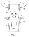
Figure 4 is a bottom view of a part of the stowage box according toFigure 1 , and of a breathing mask in position to be inserted into the stowage box; and -
Figure 5 is a section view of the pneumatic assembly offigure 2 when no breathing mask is stowed in the stowage box. - In reference to
Figure 1 , a stowage box 1 for a breathable mask (not represented) comprises a frame 3 forming a receptacle for the mask. The frame 3 comprises a substantiallyvertical side 5 which is used to fix the stowage box 1 onto a wall of the aircraft cabin and forms the bottom of the receptacle. The frame 3 further comprisessides open face 15 for inserting or extracting the mask. - On the
side 13, amortise 17 leads into the open face. Agroove 18 is formed on theside 13, at the entry of themortise 17. Thegroove 18 is linear and substantially vertical. - A
pneumatic assembly 19 is fixed at an end of themortise 17 opposite to theopen face 15. - The
pneumatic assembly 19 comprises abutton 21, afirst tube 23 coming from a breathing gas generator (not represented) and asecond tube 25 connected to the breathing mask. So the breathing mask is fed in breathable gas from the breathing gas generator through thepneumatic assembly 19. - The
pneumatic assembly 19 further comprises,Figure 2 , aduct 27 in U-shape connecting thefirst tube 23 with thesecond tube 25. - The
button 21 is the proximal end of a slidingvalve 29 having a substantially cylindrical form. Thevalve 29 slides into atube 31 running on from the base of the U of theduct 27. Thevalve 29 comprises two O-rings valve 29 and one at the distal end of thevalve 29, opposite of thebutton 21. The slidingvalve 29 comprises also acollar 37. - The
tube 31 is screwed into alarger cylinder 39 leading into theduct 27. - The
side 13 and themortise 17 are adapted,Figure 3 , to guide arigid part 41 of thebreathing mask 43, with the help of two stand-outs 45 of L-shape turned outwardly, so that thebreathing mask 43 is positioned in the frame 3. - The
rigid part 41 of the mask comprises amovable part 49, and afixed part 51 having a striated surface. The movingpart 49 comprises alug 53, adapted to be inserted into thegroove 18. - The operation of the stowage box 1 is the following.
- The pilot maintains the
breathing mask 43 by means of the twoparts movable part 49 is in an inwards position. When thebreathing mask 43 is inserted into the stowage box 1, therigid part 41 slides along theside 13 and themortise 17 guides the stand-outs 45 so that thebreathing mask 43 is in position inside the stowage box 1. The stand-outs 45 having a L-shape, the border of themortise 17 is inserted between the bottom of therigid part 41 and the feet of the stand-outs 45. When the breathing mask is in stowage position, the pilot releases themovable part 49 so that thelug 53 is inserted into thegroove 18 so that thebreathing mask 43 is maintained in the stowage position by the stand-outs 45 and thelug 53. - In stowage position, the
rigid part 41 pushes thebutton 21 and, therefore, thevalve 29 in a close position where theduct 27 is hermetically obstructed by the end of the valve and the O-ring 35. - When the pilot needs the
breathing mask 43, he pinches themovable part 49 as explained here above to move it inwards and disengage thelug 53 from thegroove 18. Then, the pilot can extract thebreathing mask 43 from the stowage box, releasing at the same time thevalve 29. The breathing gas arrives into theduct 27 through thetube 23 at a pressure of at least 3 bars. Therefore the difference of pressure between the breathable gas and the cabin pressure is such that thevalve 29 is pushed by the breathable gas and slides to an open position,Figure 5 . The O-ring 33 hermetically seals the connection between thevalve 29 and thetube 31 to avoid any leakage of breathable gas. - The
collar 37 limits the movement of thevalve 29 by butting against thetube 31 in the open position, and by butting against a shoulder of the duct in the close position. - While the invention has been illustrated and described in details in the drawings and foregoing description, such illustration and description are to be considered illustrative or exemplary and not restrictive; the invention is not limited to the disclosed embodiment.
- For instance, different means may be used to maintain the breathing mask in stowage position such as a strap crossing the open face and fixed by a hook and loop fastener.
- The
groove 18 and itscounterpart 53 are described on the right-hand side of the box. However, they may be positioned on the left-hand side or doubled on each side of the mask/box. - In another embodiment, the duct may have an L-shape with the
tube 23 running on from thevalve 29. - Though the description of the embodiment is done for a stowage box having an open face on a vertical side, the man skilled in the art understands that the described stowage box may be positioned differently, for instance with the open face on the top side of the stowage box.
- Other variations to the disclosed embodiments can be understood and effected by those skilled on the art in practicing the claimed invention, from a study of the drawings, the disclosure and the appended claims. In the claims, the word "comprising" does not exclude other elements and the indefinite article "a" or "an" does not exclude a plurality.
Claims (6)
- Stowage box for a breathing mask comprising:● a frame (3) forming a receptacle for the mask, said frame having an open face for inserting and extracting the mask, and● a pneumatic assembly (19) to control the feed of a breathing gas under pressure to the breathing mask,wherein the pneumatic assembly is adapted to close the feed of breathing gas when the mask is inserted into the frame and to open the feed of breathing gas when the mask is extracted from the frame.
- A stowage box according to claim 1, wherein the pneumatic assembly comprises a valve (29) moved by the displacement of the mask relative to the stowage box.
- A stowage box according to claim 2, wherein the valve (29) is maintained in an open position by the pressure of the breathable gas when the mask is not stowed in the frame.
- A stowage box according to claim 3, wherein the valve comprises a cylinder (29) sliding in a tube between an open position where the breathing mask is fed with the breathable gas and a close position where the feed of breathing gas is closed, and such that the breathing gas exercises a pressure to maintain the cylinder in the open position, and the breathing mask pushes the cylinder in the close position when the mask is inserted into the frame.
- A stowage box according to claim 4, wherein the frame comprises at least one substantially vertical groove (18, 47) adapted to receive a lug (53) formed on the mask, said lug having an elastic movement to engage into said groove and maintain the breathing mask inside the stowage box.
- A stowage box according to claim 4 or 5, wherein the pneumatic assembly further comprises a U-shaped duct (27) in which the breathable gas circulates, the sliding movement of said cylinder being parallel to the base of the U to blank the duct in the close position
Applications Claiming Priority (1)
| Application Number | Priority Date | Filing Date | Title |
|---|---|---|---|
| PCT/IB2007/053438 WO2009007794A1 (en) | 2007-07-10 | 2007-07-10 | Stowage box for breathing mask |
Publications (2)
| Publication Number | Publication Date |
|---|---|
| EP2185245A1 EP2185245A1 (en) | 2010-05-19 |
| EP2185245B1 true EP2185245B1 (en) | 2013-01-09 |
Family
ID=39199077
Family Applications (1)
| Application Number | Title | Priority Date | Filing Date |
|---|---|---|---|
| EP07826158A Not-in-force EP2185245B1 (en) | 2007-07-10 | 2007-07-10 | Stowage box for breathing mask |
Country Status (5)
| Country | Link |
|---|---|
| US (1) | US8863744B2 (en) |
| EP (1) | EP2185245B1 (en) |
| BR (1) | BRPI0721830B1 (en) |
| CA (1) | CA2693776C (en) |
| WO (1) | WO2009007794A1 (en) |
Families Citing this family (5)
| Publication number | Priority date | Publication date | Assignee | Title |
|---|---|---|---|---|
| US8294767B2 (en) | 2009-01-30 | 2012-10-23 | Microsoft Corporation | Body scan |
| WO2011089463A1 (en) | 2010-01-22 | 2011-07-28 | Intertechnique | Breathing assembly for aircraft |
| BR112013010509B1 (en) | 2010-12-23 | 2019-08-06 | Zodiac Aerotechnics | AIRCRAFT RESPIRATORY ASSEMBLY WITH ENHANCED MASK FIXING DEVICE |
| EP2678081B1 (en) | 2011-02-21 | 2016-04-20 | Zodiac Aerotechnics | Aircraft demand regulator and dilution regulation method |
| US20220024598A1 (en) * | 2020-07-21 | 2022-01-27 | Goodrich Corporation | Systems and methods for regulators for inflation systems for evacuation assemblies |
Family Cites Families (17)
| Publication number | Priority date | Publication date | Assignee | Title |
|---|---|---|---|---|
| US3073301A (en) * | 1958-07-16 | 1963-01-15 | Air Reduction | Aviation quick release valve |
| US4002167A (en) * | 1974-09-13 | 1977-01-11 | Minnesota Mining And Manufacturing Company | Animal gas mask assembly |
| US4625721A (en) | 1983-11-07 | 1986-12-02 | Lockheed Corporation | Smoke mask |
| US4561544A (en) * | 1983-12-28 | 1985-12-31 | Calmar, Inc. | Child resistant container |
| US4735002A (en) * | 1986-10-27 | 1988-04-05 | Rath Robert J | Surface mounted turbine-driven hair dryer |
| US5036846A (en) * | 1988-02-26 | 1991-08-06 | Puritan-Bennett Corporation | Crew oxygen mask with pneumatic comfort adjustment |
| US4915106A (en) | 1988-02-26 | 1990-04-10 | Puritan-Bennett Corporation | Crew oxygen mask with pneumatic comfort adjustment |
| US5954052A (en) * | 1997-05-21 | 1999-09-21 | Nellcor Puritan-Bennett | Safety stowage apparatus for crew oxygen masks |
| FR2778575B1 (en) | 1998-05-12 | 2000-07-28 | Intertechnique Sa | RESPIRATORY PROTECTION EQUIPMENT WITH FAST SETUP |
| US6026590A (en) * | 1998-07-10 | 2000-02-22 | Sunbeam Products, Inc. | Hair dryer with night light |
| FR2781381B1 (en) | 1998-07-24 | 2000-09-29 | Intertechnique Sa | ON-DEMAND REGULATOR FOR RESPIRATORY SYSTEM |
| US6526967B2 (en) * | 2001-06-11 | 2003-03-04 | Be Intellectual Property, Inc. | Crew oxygen mask stowage assembly including selective depressurization valve |
| FR2827178B1 (en) * | 2001-07-11 | 2003-12-05 | Intertechnique Sa | BREATHING APPARATUS AND PROTECTION DEVICE AGAINST HYPOXIA INCLUDING APPLICATION |
| US6755194B2 (en) * | 2002-04-09 | 2004-06-29 | Intertechnique, S.A. | Stowage systems, particularly for oxygen masks |
| US8997742B2 (en) * | 2002-04-23 | 2015-04-07 | Resmed Limited | Ergonomic and adjustable respiratory mask assembly with cushion |
| FR2848864B1 (en) * | 2002-12-24 | 2005-03-04 | Intertechnique Sa | RESPIRATORY GAS SUPPLY ASSEMBLY FOR AIRCRAFT AIRCRAFT PERSONNEL AND STORAGE BOX FOR RESPIRATORY EMERGENCY MASK |
| WO2011089463A1 (en) | 2010-01-22 | 2011-07-28 | Intertechnique | Breathing assembly for aircraft |
-
2007
- 2007-07-10 US US12/667,935 patent/US8863744B2/en active Active
- 2007-07-10 CA CA2693776A patent/CA2693776C/en not_active Expired - Fee Related
- 2007-07-10 BR BRPI0721830-3A patent/BRPI0721830B1/en not_active IP Right Cessation
- 2007-07-10 EP EP07826158A patent/EP2185245B1/en not_active Not-in-force
- 2007-07-10 WO PCT/IB2007/053438 patent/WO2009007794A1/en active Application Filing
Also Published As
| Publication number | Publication date |
|---|---|
| EP2185245A1 (en) | 2010-05-19 |
| WO2009007794A1 (en) | 2009-01-15 |
| CA2693776A1 (en) | 2009-01-15 |
| CA2693776C (en) | 2014-12-30 |
| BRPI0721830A2 (en) | 2013-03-12 |
| US8863744B2 (en) | 2014-10-21 |
| US20100288281A1 (en) | 2010-11-18 |
| BRPI0721830B1 (en) | 2017-11-07 |
Similar Documents
| Publication | Publication Date | Title |
|---|---|---|
| EP2185245B1 (en) | Stowage box for breathing mask | |
| CA2643825C (en) | A respiratory gas supply circuit for an aircraft carrying passengers | |
| US8393326B2 (en) | Device for oxygen supply of a user in an aircraft | |
| US6526967B2 (en) | Crew oxygen mask stowage assembly including selective depressurization valve | |
| US20070283959A1 (en) | Aircraft oxygen supply unit | |
| US8464717B2 (en) | Breathing mask with an autonomous inflatable harness | |
| CN101505835A (en) | A respiratory gas supply circuit to feed crew members and passengers of an aircraft with oxygen | |
| US10653902B2 (en) | Stowage device of emergency equipment for aircraft crewmember | |
| US8261743B2 (en) | Breathing apparatus for an aircrew member | |
| WO2017055888A1 (en) | Emergency equipment for an aircraft comprising a respiratory mask | |
| EP2525874B1 (en) | Breathing assembly for aircraft |
Legal Events
| Date | Code | Title | Description |
|---|---|---|---|
| PUAI | Public reference made under article 153(3) epc to a published international application that has entered the european phase |
Free format text: ORIGINAL CODE: 0009012 |
|
| 17P | Request for examination filed |
Effective date: 20091222 |
|
| AK | Designated contracting states |
Kind code of ref document: A1 Designated state(s): AT BE BG CH CY CZ DE DK EE ES FI FR GB GR HU IE IS IT LI LT LU LV MC MT NL PL PT RO SE SI SK TR |
|
| AX | Request for extension of the european patent |
Extension state: AL BA HR MK RS |
|
| DAX | Request for extension of the european patent (deleted) | ||
| REG | Reference to a national code |
Ref country code: DE Ref legal event code: R079 Ref document number: 602007027984 Country of ref document: DE Free format text: PREVIOUS MAIN CLASS: A62B0025000000 Ipc: B64D0010000000 |
|
| RIC1 | Information provided on ipc code assigned before grant |
Ipc: A62B 25/00 20060101ALI20120731BHEP Ipc: B64D 10/00 20060101AFI20120731BHEP |
|
| GRAP | Despatch of communication of intention to grant a patent |
Free format text: ORIGINAL CODE: EPIDOSNIGR1 |
|
| GRAS | Grant fee paid |
Free format text: ORIGINAL CODE: EPIDOSNIGR3 |
|
| GRAA | (expected) grant |
Free format text: ORIGINAL CODE: 0009210 |
|
| AK | Designated contracting states |
Kind code of ref document: B1 Designated state(s): AT BE BG CH CY CZ DE DK EE ES FI FR GB GR HU IE IS IT LI LT LU LV MC MT NL PL PT RO SE SI SK TR |
|
| REG | Reference to a national code |
Ref country code: GB Ref legal event code: FG4D |
|
| REG | Reference to a national code |
Ref country code: AT Ref legal event code: REF Ref document number: 592586 Country of ref document: AT Kind code of ref document: T Effective date: 20130115 Ref country code: CH Ref legal event code: EP |
|
| REG | Reference to a national code |
Ref country code: IE Ref legal event code: FG4D |
|
| REG | Reference to a national code |
Ref country code: DE Ref legal event code: R096 Ref document number: 602007027984 Country of ref document: DE Effective date: 20130314 |
|
| PG25 | Lapsed in a contracting state [announced via postgrant information from national office to epo] |
Ref country code: SI Free format text: LAPSE BECAUSE OF FAILURE TO SUBMIT A TRANSLATION OF THE DESCRIPTION OR TO PAY THE FEE WITHIN THE PRESCRIBED TIME-LIMIT Effective date: 20130109 |
|
| REG | Reference to a national code |
Ref country code: NL Ref legal event code: VDEP Effective date: 20130109 |
|
| REG | Reference to a national code |
Ref country code: AT Ref legal event code: MK05 Ref document number: 592586 Country of ref document: AT Kind code of ref document: T Effective date: 20130109 |
|
| REG | Reference to a national code |
Ref country code: LT Ref legal event code: MG4D |
|
| PG25 | Lapsed in a contracting state [announced via postgrant information from national office to epo] |
Ref country code: BG Free format text: LAPSE BECAUSE OF FAILURE TO SUBMIT A TRANSLATION OF THE DESCRIPTION OR TO PAY THE FEE WITHIN THE PRESCRIBED TIME-LIMIT Effective date: 20130409 Ref country code: LT Free format text: LAPSE BECAUSE OF FAILURE TO SUBMIT A TRANSLATION OF THE DESCRIPTION OR TO PAY THE FEE WITHIN THE PRESCRIBED TIME-LIMIT Effective date: 20130109 Ref country code: AT Free format text: LAPSE BECAUSE OF FAILURE TO SUBMIT A TRANSLATION OF THE DESCRIPTION OR TO PAY THE FEE WITHIN THE PRESCRIBED TIME-LIMIT Effective date: 20130109 Ref country code: BE Free format text: LAPSE BECAUSE OF FAILURE TO SUBMIT A TRANSLATION OF THE DESCRIPTION OR TO PAY THE FEE WITHIN THE PRESCRIBED TIME-LIMIT Effective date: 20130109 Ref country code: ES Free format text: LAPSE BECAUSE OF FAILURE TO SUBMIT A TRANSLATION OF THE DESCRIPTION OR TO PAY THE FEE WITHIN THE PRESCRIBED TIME-LIMIT Effective date: 20130420 Ref country code: SE Free format text: LAPSE BECAUSE OF FAILURE TO SUBMIT A TRANSLATION OF THE DESCRIPTION OR TO PAY THE FEE WITHIN THE PRESCRIBED TIME-LIMIT Effective date: 20130109 Ref country code: IS Free format text: LAPSE BECAUSE OF FAILURE TO SUBMIT A TRANSLATION OF THE DESCRIPTION OR TO PAY THE FEE WITHIN THE PRESCRIBED TIME-LIMIT Effective date: 20130509 |
|
| PG25 | Lapsed in a contracting state [announced via postgrant information from national office to epo] |
Ref country code: FI Free format text: LAPSE BECAUSE OF FAILURE TO SUBMIT A TRANSLATION OF THE DESCRIPTION OR TO PAY THE FEE WITHIN THE PRESCRIBED TIME-LIMIT Effective date: 20130109 Ref country code: PT Free format text: LAPSE BECAUSE OF FAILURE TO SUBMIT A TRANSLATION OF THE DESCRIPTION OR TO PAY THE FEE WITHIN THE PRESCRIBED TIME-LIMIT Effective date: 20130509 Ref country code: NL Free format text: LAPSE BECAUSE OF FAILURE TO SUBMIT A TRANSLATION OF THE DESCRIPTION OR TO PAY THE FEE WITHIN THE PRESCRIBED TIME-LIMIT Effective date: 20130109 Ref country code: PL Free format text: LAPSE BECAUSE OF FAILURE TO SUBMIT A TRANSLATION OF THE DESCRIPTION OR TO PAY THE FEE WITHIN THE PRESCRIBED TIME-LIMIT Effective date: 20130109 Ref country code: LV Free format text: LAPSE BECAUSE OF FAILURE TO SUBMIT A TRANSLATION OF THE DESCRIPTION OR TO PAY THE FEE WITHIN THE PRESCRIBED TIME-LIMIT Effective date: 20130109 Ref country code: GR Free format text: LAPSE BECAUSE OF FAILURE TO SUBMIT A TRANSLATION OF THE DESCRIPTION OR TO PAY THE FEE WITHIN THE PRESCRIBED TIME-LIMIT Effective date: 20130410 |
|
| PG25 | Lapsed in a contracting state [announced via postgrant information from national office to epo] |
Ref country code: EE Free format text: LAPSE BECAUSE OF FAILURE TO SUBMIT A TRANSLATION OF THE DESCRIPTION OR TO PAY THE FEE WITHIN THE PRESCRIBED TIME-LIMIT Effective date: 20130109 Ref country code: SK Free format text: LAPSE BECAUSE OF FAILURE TO SUBMIT A TRANSLATION OF THE DESCRIPTION OR TO PAY THE FEE WITHIN THE PRESCRIBED TIME-LIMIT Effective date: 20130109 Ref country code: CZ Free format text: LAPSE BECAUSE OF FAILURE TO SUBMIT A TRANSLATION OF THE DESCRIPTION OR TO PAY THE FEE WITHIN THE PRESCRIBED TIME-LIMIT Effective date: 20130109 Ref country code: DK Free format text: LAPSE BECAUSE OF FAILURE TO SUBMIT A TRANSLATION OF THE DESCRIPTION OR TO PAY THE FEE WITHIN THE PRESCRIBED TIME-LIMIT Effective date: 20130109 Ref country code: RO Free format text: LAPSE BECAUSE OF FAILURE TO SUBMIT A TRANSLATION OF THE DESCRIPTION OR TO PAY THE FEE WITHIN THE PRESCRIBED TIME-LIMIT Effective date: 20130109 |
|
| PLBE | No opposition filed within time limit |
Free format text: ORIGINAL CODE: 0009261 |
|
| STAA | Information on the status of an ep patent application or granted ep patent |
Free format text: STATUS: NO OPPOSITION FILED WITHIN TIME LIMIT |
|
| PG25 | Lapsed in a contracting state [announced via postgrant information from national office to epo] |
Ref country code: CY Free format text: LAPSE BECAUSE OF FAILURE TO SUBMIT A TRANSLATION OF THE DESCRIPTION OR TO PAY THE FEE WITHIN THE PRESCRIBED TIME-LIMIT Effective date: 20130109 |
|
| 26N | No opposition filed |
Effective date: 20131010 |
|
| PG25 | Lapsed in a contracting state [announced via postgrant information from national office to epo] |
Ref country code: IT Free format text: LAPSE BECAUSE OF FAILURE TO SUBMIT A TRANSLATION OF THE DESCRIPTION OR TO PAY THE FEE WITHIN THE PRESCRIBED TIME-LIMIT Effective date: 20130109 |
|
| REG | Reference to a national code |
Ref country code: DE Ref legal event code: R097 Ref document number: 602007027984 Country of ref document: DE Effective date: 20131010 |
|
| PG25 | Lapsed in a contracting state [announced via postgrant information from national office to epo] |
Ref country code: MC Free format text: LAPSE BECAUSE OF FAILURE TO SUBMIT A TRANSLATION OF THE DESCRIPTION OR TO PAY THE FEE WITHIN THE PRESCRIBED TIME-LIMIT Effective date: 20130109 |
|
| REG | Reference to a national code |
Ref country code: CH Ref legal event code: PL |
|
| GBPC | Gb: european patent ceased through non-payment of renewal fee |
Effective date: 20130710 |
|
| REG | Reference to a national code |
Ref country code: IE Ref legal event code: MM4A |
|
| PG25 | Lapsed in a contracting state [announced via postgrant information from national office to epo] |
Ref country code: CH Free format text: LAPSE BECAUSE OF NON-PAYMENT OF DUE FEES Effective date: 20130731 Ref country code: GB Free format text: LAPSE BECAUSE OF NON-PAYMENT OF DUE FEES Effective date: 20130710 Ref country code: LI Free format text: LAPSE BECAUSE OF NON-PAYMENT OF DUE FEES Effective date: 20130731 |
|
| PG25 | Lapsed in a contracting state [announced via postgrant information from national office to epo] |
Ref country code: IE Free format text: LAPSE BECAUSE OF NON-PAYMENT OF DUE FEES Effective date: 20130710 |
|
| REG | Reference to a national code |
Ref country code: FR Ref legal event code: CD Owner name: ZODIAC AEROTECHNICS, FR Effective date: 20141119 |
|
| REG | Reference to a national code |
Ref country code: DE Ref legal event code: R081 Ref document number: 602007027984 Country of ref document: DE Owner name: ZODIAC AEROTECHNICS, FR Free format text: FORMER OWNER: INTERTECHNIQUE, PLAISIR, SEINE-ET-OISE, FR Effective date: 20141117 |
|
| PG25 | Lapsed in a contracting state [announced via postgrant information from national office to epo] |
Ref country code: TR Free format text: LAPSE BECAUSE OF FAILURE TO SUBMIT A TRANSLATION OF THE DESCRIPTION OR TO PAY THE FEE WITHIN THE PRESCRIBED TIME-LIMIT Effective date: 20130109 Ref country code: MT Free format text: LAPSE BECAUSE OF FAILURE TO SUBMIT A TRANSLATION OF THE DESCRIPTION OR TO PAY THE FEE WITHIN THE PRESCRIBED TIME-LIMIT Effective date: 20130109 |
|
| REG | Reference to a national code |
Ref country code: FR Ref legal event code: PLFP Year of fee payment: 9 |
|
| PG25 | Lapsed in a contracting state [announced via postgrant information from national office to epo] |
Ref country code: HU Free format text: LAPSE BECAUSE OF FAILURE TO SUBMIT A TRANSLATION OF THE DESCRIPTION OR TO PAY THE FEE WITHIN THE PRESCRIBED TIME-LIMIT; INVALID AB INITIO Effective date: 20070710 Ref country code: LU Free format text: LAPSE BECAUSE OF NON-PAYMENT OF DUE FEES Effective date: 20130710 |
|
| REG | Reference to a national code |
Ref country code: FR Ref legal event code: PLFP Year of fee payment: 10 |
|
| REG | Reference to a national code |
Ref country code: FR Ref legal event code: PLFP Year of fee payment: 11 |
|
| REG | Reference to a national code |
Ref country code: FR Ref legal event code: PLFP Year of fee payment: 12 |
|
| PGFP | Annual fee paid to national office [announced via postgrant information from national office to epo] |
Ref country code: FR Payment date: 20190621 Year of fee payment: 13 |
|
| PGFP | Annual fee paid to national office [announced via postgrant information from national office to epo] |
Ref country code: DE Payment date: 20190620 Year of fee payment: 13 |
|
| REG | Reference to a national code |
Ref country code: DE Ref legal event code: R119 Ref document number: 602007027984 Country of ref document: DE |
|
| PG25 | Lapsed in a contracting state [announced via postgrant information from national office to epo] |
Ref country code: FR Free format text: LAPSE BECAUSE OF NON-PAYMENT OF DUE FEES Effective date: 20200731 |
|
| PG25 | Lapsed in a contracting state [announced via postgrant information from national office to epo] |
Ref country code: DE Free format text: LAPSE BECAUSE OF NON-PAYMENT OF DUE FEES Effective date: 20210202 |