EP2184796A1 - Electric energy storage device and its manufacturing method - Google Patents
Electric energy storage device and its manufacturing method Download PDFInfo
- Publication number
- EP2184796A1 EP2184796A1 EP07791109A EP07791109A EP2184796A1 EP 2184796 A1 EP2184796 A1 EP 2184796A1 EP 07791109 A EP07791109 A EP 07791109A EP 07791109 A EP07791109 A EP 07791109A EP 2184796 A1 EP2184796 A1 EP 2184796A1
- Authority
- EP
- European Patent Office
- Prior art keywords
- internal
- insulating member
- package body
- outer package
- lead
- Prior art date
- Legal status (The legal status is an assumption and is not a legal conclusion. Google has not performed a legal analysis and makes no representation as to the accuracy of the status listed.)
- Granted
Links
Images


Classifications
-
- H—ELECTRICITY
- H01—ELECTRIC ELEMENTS
- H01M—PROCESSES OR MEANS, e.g. BATTERIES, FOR THE DIRECT CONVERSION OF CHEMICAL ENERGY INTO ELECTRICAL ENERGY
- H01M10/00—Secondary cells; Manufacture thereof
- H01M10/04—Construction or manufacture in general
- H01M10/0413—Large-sized flat cells or batteries for motive or stationary systems with plate-like electrodes
-
- H—ELECTRICITY
- H01—ELECTRIC ELEMENTS
- H01M—PROCESSES OR MEANS, e.g. BATTERIES, FOR THE DIRECT CONVERSION OF CHEMICAL ENERGY INTO ELECTRICAL ENERGY
- H01M10/00—Secondary cells; Manufacture thereof
- H01M10/05—Accumulators with non-aqueous electrolyte
- H01M10/052—Li-accumulators
- H01M10/0525—Rocking-chair batteries, i.e. batteries with lithium insertion or intercalation in both electrodes; Lithium-ion batteries
-
- H—ELECTRICITY
- H01—ELECTRIC ELEMENTS
- H01M—PROCESSES OR MEANS, e.g. BATTERIES, FOR THE DIRECT CONVERSION OF CHEMICAL ENERGY INTO ELECTRICAL ENERGY
- H01M50/00—Constructional details or processes of manufacture of the non-active parts of electrochemical cells other than fuel cells, e.g. hybrid cells
- H01M50/10—Primary casings; Jackets or wrappings
- H01M50/172—Arrangements of electric connectors penetrating the casing
- H01M50/174—Arrangements of electric connectors penetrating the casing adapted for the shape of the cells
- H01M50/178—Arrangements of electric connectors penetrating the casing adapted for the shape of the cells for pouch or flexible bag cells
-
- H—ELECTRICITY
- H01—ELECTRIC ELEMENTS
- H01M—PROCESSES OR MEANS, e.g. BATTERIES, FOR THE DIRECT CONVERSION OF CHEMICAL ENERGY INTO ELECTRICAL ENERGY
- H01M50/00—Constructional details or processes of manufacture of the non-active parts of electrochemical cells other than fuel cells, e.g. hybrid cells
- H01M50/50—Current conducting connections for cells or batteries
- H01M50/528—Fixed electrical connections, i.e. not intended for disconnection
-
- H—ELECTRICITY
- H01—ELECTRIC ELEMENTS
- H01M—PROCESSES OR MEANS, e.g. BATTERIES, FOR THE DIRECT CONVERSION OF CHEMICAL ENERGY INTO ELECTRICAL ENERGY
- H01M50/00—Constructional details or processes of manufacture of the non-active parts of electrochemical cells other than fuel cells, e.g. hybrid cells
- H01M50/50—Current conducting connections for cells or batteries
- H01M50/543—Terminals
- H01M50/547—Terminals characterised by the disposition of the terminals on the cells
- H01M50/55—Terminals characterised by the disposition of the terminals on the cells on the same side of the cell
-
- H—ELECTRICITY
- H01—ELECTRIC ELEMENTS
- H01M—PROCESSES OR MEANS, e.g. BATTERIES, FOR THE DIRECT CONVERSION OF CHEMICAL ENERGY INTO ELECTRICAL ENERGY
- H01M50/00—Constructional details or processes of manufacture of the non-active parts of electrochemical cells other than fuel cells, e.g. hybrid cells
- H01M50/50—Current conducting connections for cells or batteries
- H01M50/543—Terminals
- H01M50/552—Terminals characterised by their shape
- H01M50/553—Terminals adapted for prismatic, pouch or rectangular cells
- H01M50/557—Plate-shaped terminals
-
- H—ELECTRICITY
- H01—ELECTRIC ELEMENTS
- H01M—PROCESSES OR MEANS, e.g. BATTERIES, FOR THE DIRECT CONVERSION OF CHEMICAL ENERGY INTO ELECTRICAL ENERGY
- H01M50/00—Constructional details or processes of manufacture of the non-active parts of electrochemical cells other than fuel cells, e.g. hybrid cells
- H01M50/50—Current conducting connections for cells or batteries
- H01M50/543—Terminals
- H01M50/562—Terminals characterised by the material
-
- H—ELECTRICITY
- H01—ELECTRIC ELEMENTS
- H01M—PROCESSES OR MEANS, e.g. BATTERIES, FOR THE DIRECT CONVERSION OF CHEMICAL ENERGY INTO ELECTRICAL ENERGY
- H01M50/00—Constructional details or processes of manufacture of the non-active parts of electrochemical cells other than fuel cells, e.g. hybrid cells
- H01M50/50—Current conducting connections for cells or batteries
- H01M50/543—Terminals
- H01M50/564—Terminals characterised by their manufacturing process
- H01M50/567—Terminals characterised by their manufacturing process by fixing means, e.g. screws, rivets or bolts
-
- H—ELECTRICITY
- H01—ELECTRIC ELEMENTS
- H01M—PROCESSES OR MEANS, e.g. BATTERIES, FOR THE DIRECT CONVERSION OF CHEMICAL ENERGY INTO ELECTRICAL ENERGY
- H01M50/00—Constructional details or processes of manufacture of the non-active parts of electrochemical cells other than fuel cells, e.g. hybrid cells
- H01M50/50—Current conducting connections for cells or batteries
- H01M50/572—Means for preventing undesired use or discharge
- H01M50/574—Devices or arrangements for the interruption of current
- H01M50/579—Devices or arrangements for the interruption of current in response to shock
-
- H—ELECTRICITY
- H01—ELECTRIC ELEMENTS
- H01M—PROCESSES OR MEANS, e.g. BATTERIES, FOR THE DIRECT CONVERSION OF CHEMICAL ENERGY INTO ELECTRICAL ENERGY
- H01M10/00—Secondary cells; Manufacture thereof
- H01M10/05—Accumulators with non-aqueous electrolyte
- H01M10/058—Construction or manufacture
-
- H—ELECTRICITY
- H01—ELECTRIC ELEMENTS
- H01M—PROCESSES OR MEANS, e.g. BATTERIES, FOR THE DIRECT CONVERSION OF CHEMICAL ENERGY INTO ELECTRICAL ENERGY
- H01M50/00—Constructional details or processes of manufacture of the non-active parts of electrochemical cells other than fuel cells, e.g. hybrid cells
- H01M50/10—Primary casings; Jackets or wrappings
- H01M50/116—Primary casings; Jackets or wrappings characterised by the material
- H01M50/124—Primary casings; Jackets or wrappings characterised by the material having a layered structure
-
- Y—GENERAL TAGGING OF NEW TECHNOLOGICAL DEVELOPMENTS; GENERAL TAGGING OF CROSS-SECTIONAL TECHNOLOGIES SPANNING OVER SEVERAL SECTIONS OF THE IPC; TECHNICAL SUBJECTS COVERED BY FORMER USPC CROSS-REFERENCE ART COLLECTIONS [XRACs] AND DIGESTS
- Y02—TECHNOLOGIES OR APPLICATIONS FOR MITIGATION OR ADAPTATION AGAINST CLIMATE CHANGE
- Y02E—REDUCTION OF GREENHOUSE GAS [GHG] EMISSIONS, RELATED TO ENERGY GENERATION, TRANSMISSION OR DISTRIBUTION
- Y02E60/00—Enabling technologies; Technologies with a potential or indirect contribution to GHG emissions mitigation
- Y02E60/10—Energy storage using batteries
-
- Y—GENERAL TAGGING OF NEW TECHNOLOGICAL DEVELOPMENTS; GENERAL TAGGING OF CROSS-SECTIONAL TECHNOLOGIES SPANNING OVER SEVERAL SECTIONS OF THE IPC; TECHNICAL SUBJECTS COVERED BY FORMER USPC CROSS-REFERENCE ART COLLECTIONS [XRACs] AND DIGESTS
- Y02—TECHNOLOGIES OR APPLICATIONS FOR MITIGATION OR ADAPTATION AGAINST CLIMATE CHANGE
- Y02P—CLIMATE CHANGE MITIGATION TECHNOLOGIES IN THE PRODUCTION OR PROCESSING OF GOODS
- Y02P70/00—Climate change mitigation technologies in the production process for final industrial or consumer products
- Y02P70/50—Manufacturing or production processes characterised by the final manufactured product
-
- Y—GENERAL TAGGING OF NEW TECHNOLOGICAL DEVELOPMENTS; GENERAL TAGGING OF CROSS-SECTIONAL TECHNOLOGIES SPANNING OVER SEVERAL SECTIONS OF THE IPC; TECHNICAL SUBJECTS COVERED BY FORMER USPC CROSS-REFERENCE ART COLLECTIONS [XRACs] AND DIGESTS
- Y02—TECHNOLOGIES OR APPLICATIONS FOR MITIGATION OR ADAPTATION AGAINST CLIMATE CHANGE
- Y02T—CLIMATE CHANGE MITIGATION TECHNOLOGIES RELATED TO TRANSPORTATION
- Y02T10/00—Road transport of goods or passengers
- Y02T10/60—Other road transportation technologies with climate change mitigation effect
- Y02T10/70—Energy storage systems for electromobility, e.g. batteries
-
- Y—GENERAL TAGGING OF NEW TECHNOLOGICAL DEVELOPMENTS; GENERAL TAGGING OF CROSS-SECTIONAL TECHNOLOGIES SPANNING OVER SEVERAL SECTIONS OF THE IPC; TECHNICAL SUBJECTS COVERED BY FORMER USPC CROSS-REFERENCE ART COLLECTIONS [XRACs] AND DIGESTS
- Y10—TECHNICAL SUBJECTS COVERED BY FORMER USPC
- Y10T—TECHNICAL SUBJECTS COVERED BY FORMER US CLASSIFICATION
- Y10T156/00—Adhesive bonding and miscellaneous chemical manufacture
- Y10T156/10—Methods of surface bonding and/or assembly therefor
- Y10T156/1052—Methods of surface bonding and/or assembly therefor with cutting, punching, tearing or severing
- Y10T156/1056—Perforating lamina
-
- Y—GENERAL TAGGING OF NEW TECHNOLOGICAL DEVELOPMENTS; GENERAL TAGGING OF CROSS-SECTIONAL TECHNOLOGIES SPANNING OVER SEVERAL SECTIONS OF THE IPC; TECHNICAL SUBJECTS COVERED BY FORMER USPC CROSS-REFERENCE ART COLLECTIONS [XRACs] AND DIGESTS
- Y10—TECHNICAL SUBJECTS COVERED BY FORMER USPC
- Y10T—TECHNICAL SUBJECTS COVERED BY FORMER US CLASSIFICATION
- Y10T29/00—Metal working
- Y10T29/49—Method of mechanical manufacture
- Y10T29/49002—Electrical device making
- Y10T29/49108—Electric battery cell making
Definitions
- the present invention relates to an electric energy storage device, such as a lithium ion secondary battery, a lithium secondary battery, a polymer secondary battery, or an electric double-layer capacitor.
- a sheet-like lithium ion secondary battery which is lightweight, thin, and flexible and which has a flexible outer package body as a battery case comprising a multilayered laminated film including an internal layer formed of a thermoplastic resin with good electrolysis-solution tolerability and heat seal characteristics, such as polyethylene or polypropylene, a middle layer formed of a metal foil with good flexibility and strength like an aluminum foil, and an external layer formed of an insulating resin with a good electrical insulation property like polyamide, and wherein a sheet-like internal electrode pair and an electrolysis solution are filled in the outer package body (see, for example, patent literatures 1 and 2).
- Patent literature 1 discloses a sheet-like secondary battery comprising an internal electrode pair including a sheet-like positive electrode, a separator, and a sheet-like negative electrode all stacked together, an outer package body retaining the internal electrode pair thereinside, an internal lead connected to the internal electrode pair, an external lead sandwiching the outer package body and arranged outwardly thereof, and connection means for electrically connecting the internal lead and the external lead together by airtightly passing all the way through the outer package body, and the outer package body is firmly and airtightly held between the internal lead and the external lead to improve the sealing property and the connection reliability.
- Patent literature 2 discloses a secondary battery comprising an electrode body with a protrusion, and an outer package body covering and wrapping the electrode body, the protrusion passes all the way through the outer package body and protrudes to the exterior of the battery, a sealing member is provided around the protrusion, and an insulating material is provided at a portion where the protrusion contacts the outer package body.
- a sealing member 5 which seals a space between the protrusion and the outer package film is provided around the entire periphery of the protrusion 41, thereby suppressing any short-circuiting as the protrusion 41 contacts a metal foil of the outer package film 3 when the protrusion 41 of an external terminal 4 passes all the way through the outer package film 3.
- the present invention has been made in view of the foregoing problems of the conventional technologies, and it is an object of the present invention to provide an electric energy storage device which has a connection structure with a good connection reliability, and which can suppress any contact of a connection terminal with an outer package body with a simple structure.
- an electric energy storage device set forth in claim 1 comprises: a battery element retained in an outer package body having at least a metal layer; a tabular internal lead connected to the battery element in the outer package body:, a tabular external lead arranged outside the outer package body so as to face the internal lead; a connection terminal electrically connecting the internal lead and the external lead together; an internal insulating member provided between the outer package body and the internal lead along an internal surface of the outer package body; and an external insulating member provided between the outer package body and the external lead along an external surface of the outer package body so as to face the internal insulating member, and wherein the connection terminal includes a penetration shaft passing all the way through the external lead, the external insulating member, the outer package body, the internal insulating member, and the internal lead, and flanges integrally formed at both ends of the penetration shaft, the flanges at both ends of the connection terminal depress and sandwich the external insulating member, the outer package body, and the internal insulating member between the tabular external lead and
- the flange integrally formed means a part integrally and continuously formed with an end portion of the metallic penetration shaft, formed of the same material as that of the penetration shaft, and formed in a flanged shape having a larger cross-section than the cross-section of the penetration shaft in the radial direction.
- the electric energy storage device set forth in claim 2 has a structure according to claim 1, and wherein respective through-holes of the external insulating member and the internal insulating member through which the penetration shaft of the connection terminal passes are so formed as to have a substantially equal diameter to a diameter of the penetration shaft, and a through-hole of the outer package body through which the penetration shaft of the connection terminal passes is so formed as to have a larger diameter than the diameter of the penetration shaft beforehand.
- the electric energy storage device set forth in claim 3 has a structure according to claim 1 or 2, and wherein the outer package body is a multilayered outer package body further having an internal layer formed of a thermoplastic resin which can be heat-sealed, and the internal insulating member also functions as internal-layer protecting means for suppressing any damage of the internal layer of the multilayered outer package body as the internal insulating member covers at least a part of any one of the battery element, the internal lead, and the connection terminal.
- the electric energy storage device set forth in claim 4 has a structure according to claim 3, and wherein the internal insulating member covers an end portion of the internal lead in the vicinity of the internal layer of the multilayered outer package body across a lengthwise direction of the internal lead.
- the electric energy storage device set forth in claim 5 has a structure according to claim 3 or 4, and wherein the internal insulating member covers the flange of the connection terminal in the vicinity of the internal layer of the multilayered outer package body.
- the electric energy storage device set forth in claim 6 has a structure according to any one of claims 3 to 5, and wherein the internal insulating member has a cross-section formed in a rectangular shape without one side, and the rectangle without one side includes a part along the internal layer of the multilayered outer package body, a part covering the end portion of the internal lead, and a part covering the flange of the connection terminal.
- the electric energy storage device set forth in claim 7 has a structure according to any one of claims 1 to 6, and wherein a plurality of connection terminals are provided for each of the tabular external lead and internal lead.
- the electric energy storage device set forth in claim 8 has a structure according to any one of claims 1 to 7, and wherein the connection terminal is a rivet joined to each of the tabular external lead and internal lead.
- the electric energy storage device set forth in claim 9 has a structure according to any one of claims 1 to 8, and wherein the connection terminal is formed of a same material as a material of at least the internal lead.
- the electric energy storage device set forth in claim 10 has a structure according to any one of claims 1 to 9, and wherein the internal insulating member is formed of polypropylene, polyethylene, polystyrene, polyamide or ionomer having a higher melting point than a melting point of the internal layer which can be heat-sealed.
- the electric energy storage device set forth in claim 11 has a structure according to any one of claims 1 to 10, and wherein the electric energy storage device is a lithium ion secondary battery used under a high voltage larger than or equal to 100 V.
- a manufacturing method of an electric energy storage device set forth in claim 12 manufactures the electric energy storage device that comprises a battery element retained in an outer package body having at least a metal layer, a tabular internal lead connected to the battery element in the outer package body, a tabular external lead arranged outside the outer package body so as to face the internal lead, a connection terminal electrically connecting the internal lead and the external lead together, an internal insulating member provided between the outer package body and the internal lead along an internal surface of the outer package body, and an external insulating member provided between the outer package body and the external lead along an external surface of the outer package body so as to face the internal insulating member, the manufacturing method comprises: preparing a connection terminal including a penetration shaft and a flange formed at one end of the penetration shaft beforehand; forming respective through-holes of the external lead, the external insulating member, the internal insulating member, and the internal lead through which the penetration shaft of the connection terminal passes so as to have a substantially equal diameter to a diameter of the penetration shaft; forming a through-
- the electric energy storage device manufacturing method set forth in claim 13 has steps according to claim 12, and wherein the outer package body is a multilayered outer package body further including an internal layer formed of a thermoplastic resin which can be heat-sealed, and after the external lead, the external insulating members, the outer package body, the internal insulating member, and the internal lead are connected together by the connection terminal, the internal insulating member is folded at an end portion of the internal lead to cover the end portion of the internal lead, an end portion of the battery element, and the flange of the connection terminal so that the internal insulating member follows surfaces of the end portion of the internal lead, the end portion of the battery element, and the flange of the connection terminal, and is retained in the outer package body
- connection terminal having the flanges integrally formed with the penetration shaft presses and holds the external lead, a good sealing property is ensured between the connection terminal and the external lead, the external insulating member and/or the internal insulating member pressed in between the penetration shaft and the metal layer of the outer package body surely suppresses any contact of the penetration shaft of the connection terminal with the metal layer, so that the electric energy storage device having a good insulation reliability can be realized with a simple structure.
- a space is formed between the penetration shaft of the connection terminal and the metal layer of the outer package body, so that press-in of the external insulating member and/or the internal insulating member is surely promoted by caulking pressure with a simple structure.
- the internal insulating member also functions as the internal-layer protecting means for suppressing any damage due to a contact of the internal layer with metal parts, such as the battery element, the internal lead, and the connection terminal, it is possible to effectively suppress deterioration of the productivity and cost-up inherent to increasing of the number of parts and work processes, and a contact of the metal layer of the outer package body with the metal parts due to the damage of the internal layer can be suppressed before it happens.
- the internal insulating member has a cross-section formed in a rectangular shape without one side, as a part of the internal insulating member along the internal surface of the outer package body (corresponding to an upper part of the rectangle without one side) is sandwiched between the internal lead and the outer package body, it is unnecessary to fix a part which covers the end portion of the internal lead (corresponding to a side of the rectangle without one side) and a part covering the internal flange (corresponding to a lower part of the rectangle without one side) by means of adhesive or the like, so that alignment is easily accomplished.
- connection reliability with respect to the external lead is improved, and in comparison with a structure that separate insulating members are provided for individual plural penetration shafts, the connection workability with respect to the external lead is further improved.
- connection terminal As the rivet is used as the connection terminal, it is possible to connect the internal lead and the external lead together by a relatively-simple and inexpensive technique.
- the internal insulating member is formed of a resin material having a higher melting point than the internal layer, it is possible to suppress any effect of heat at the time of heat-sealing to the internal insulating member.
- the electric energy storage device set forth in claim 11 for example, several tens of the electric energy storage devices are connected in series, and can be applied to a hybrid vehicle (HEV) or an electric vehicle (EV) under a high voltage larger than or equal to 100 V (e.g., 500 V).
- HEV hybrid vehicle
- EV electric vehicle
- the electric energy storage device manufacturing method set forth in claim 12 by applying caulking pressure through the tabular external lead and internal lead, it is possible to suppress any local pressurization to the insulating member and the outer package body which causes a damage, and the external insulating member and/or internal insulating member provided at each surface of the outer package body is pressed in a space between the through-hole of the outer package body so formed as to have a larger diameter than the penetration shaft beforehand and the penetration shaft by uniform planer pressure, so that it is possible to easily provide the electric energy storage device surely having a connection reliability and a insulation reliability around the penetration shaft.
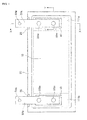
- FIG. 1 is a plan view showing the electric energy storage device of the present invention
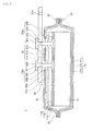
- FIG. 2 is a cross-sectional view along a line X-X in FIG. 1
- FIG. 3 is a cross-sectional view along a line Y-Y in FIG. 1
- FIG. 4 is an explanatory diagram for a battery element 10
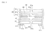
- FIG. 5 is a partial explanatory diagram in the vicinity of a through-hole of the electric energy storage device (note that FIGS. 2 , 3 and 5 are a cross-sectional view and a partial explanatory diagram at a positive electrode side, but the structures at a negative electrode side are same as those of the positive electrode side).
- a lithium ion secondary battery 1 which is an example of the electric energy storage device of the present invention comprises a sheet-like battery element 10 including plural sheet-like positive electrodes 10a and plural sheet-like negative electrodes 10b alternately stacked together via separators 15, a flexible outer package body 20 for sealing and retaining the battery element 10 and a non-illustrated electrolysis solution thereinside, a positive-electrode internal lead 31a which connect individual positive electrodes 10a of the battery element 10 together inside the outer package body 20, a negative-electrode internal lead 31b which connects individual negative electrodes 10b of the battery element 10 together inside the outer package body 20, a positive terminal external lead 32a which is arranged at an external part of the outer package body 20 that corresponds to the positive-electrode internal lead 31a via the outer package body 20, a negative terminal external lead 32b which is arranged at an external part of the outer package body 20 that corresponds to the negative-electrode internal lead via the outer package body 20, and two
- each internal lead 31 a, 31b and the outer package body 20 and between each external lead 32a, 32b and the outer package body 20 are internal insulating member 41 and external insulating member 43 each sealing individual through-holes of the outer package body 20 where the rivets 33a 1 , 33a 2 , 33b 1 , 33b 2 passes through, and ensuring the insulation property between a surface of the outer package body 20 and each internal lead 31a, 31b and each external lead 32a, 32b.
- the battery element 10 comprises the plurality of reed-shaped positive electrodes 10a and the plurality of reed-shaped negative electrodes 10b alternately stacked together via the plurality of reed-shaped separator 15.
- the positive electrode 10a has a positive electrode collector 11a with a positive electrode activation material 12a stacked on both surfaces thereof.
- the positive electrode collector 11a is formed of aluminum, and the positive electrode activation material 12a is a lithium-cobaltate composite oxide (LCO).
- the negative electrode 10b has a negative electrode collector 11b with a negative electrode activation material 12b stacked on both surfaces thereof.
- the negative electrode collector 11b is formed of copper, and the negative electrode activation material 12b is a carbon material.
- An end portion 111a of the plural positive electrode collectors 11a forming the plural positive electrodes 10a and an end portion 111b of the plural negative electrode collectors 11b forming the plural negative electrodes 10b are stacked on corresponding positive-electrode internal lead 31a and negative-electrode internal lead 31b, respectively, and connected thereto by ultrasonic welding or the like.
- the battery element 10 employs a stacked sheet-feed structure having the reed-shaped positive electrodes, negative electrodes, and separators stacked together, but a rolled structure of rolling up lengthy positive electrode, negative electrode, and separator may be employed (for example, such a structure can be realized by pulling out respective end portions of the positive and negative electrode collectors up and down along the rolling axis, and by connecting the connection terminals of the embodiment to such end portions).
- the battery element 10 is not limited to any particular one if it can be used for an electric energy storage device, such as a lithium ion secondary battery, a lithium secondary battery, a polymer secondary battery, or an electric double-layer capacitor.
- the separator 15 is not limited to any particular one, and one conventionally well-known can be used. Regarding the separator of the present invention, the meaning must not be limited by such a name, and a solid electrolyte material or a gel electrolyte material which can function (serve) as a separator can be used instead of the separator. Moreover, a separator containing an inorganic material can be used.
- the positive electrode activation material 12a in addition to lithium-cobalt composite oxide (LCO), a lithium-mangan composite material (LMO), or a lithium-nickel composite oxide (LNO) can be used. Moreover, a ternary element material like LNMCO or a binary element material, such as LMNO, LMCO, or LNCO can be used. Furthermore, a mixture of those materials can be used.
- LCO lithium-cobalt composite oxide
- LMO lithium-mangan composite material
- LNO lithium-nickel composite oxide
- a ternary element material like LNMCO or a binary element material, such as LMNO, LMCO, or LNCO can be used. Furthermore, a mixture of those materials can be used.
- carbon material for the negative electrode activation material 12b graphite or hard carbon can be used. Moreover, a mixture of those materials can be used.
- the outer package body 20 of the present invention comprises laminated films with a three-layer structure each having an internal layer 21a (thickness: 30 to 120 ⁇ m) formed of polypropylene, a middle layer 21b (thickness: 30 to 50 ⁇ m) formed of an aluminum foil or an aluminum-alloy foil, and an external layer 21c (thickness: 20 to 40 ⁇ m) formed of nylon.
- Through-hole of the outer package body 20 where the rivet 33a 1 , 33a 2 passes through has a diameter set to be larger than the diameter of the shaft of the rivet beforehand.
- the outer package body 20 has two laminated films formed in a cupped shape and overlapped with each other, and a heat-seal part 23 around the four sides of the overlapped laminated films is heat-sealed (thermal welding) to join the internal layers 21a together, thereby sealing the battery element 10 inside the outer package body 20.
- the laminated film is lightweight, has a superior flexibility, and has superior blocking function and sealing property against water or the like from the exterior.
- an insulating film 25 (e.g., Kapton (registered trademark)) formed of a polyimide resin with a heat resisting property and an electric insulating property is provided around the edge of heat-seal part 23 of the outer package body 20 in the vicinity of the external lead 32a, 32b in the thickness direction of the outer package body 20 in order to suppress any short-circuiting as the external lead 32 contacts the middle layer (metal layer) 21b.
- Kapton registered trademark
- the outer package body 20 comprises the laminated films with a three-layer structure, but the outer package body 20 may be structured in such a way that the major part (main plane) of the outer package body 20 is formed of a metal layer and an internal layer 21a has the heat-seal part 23 only which can be subjected to heat-sealing.
- a metal having a barrier property against water, a flexibility and a superior strength can be used, and stainless, nickel, or a nickel alloy, copper or a copper alloy, iron or an iron alloy can be used.
- the metal layer 21b one which is in a foil-like shape (thin tabular shape) beforehand can be used, but one having undergone thin-film formation or plating can be used.
- the metal layer 21b may employ a multilayer structure.
- the internal layer 21a and the external layer 21c may also employ a multilayer structure.
- the internal layer 21a can be formed of a thermoplastic resin with good electrolysis-solution tolerability and heat seal property, such as polyethylene, polystyrene, polyamide, or ionomer.
- the external layer 21c can be formed of an insulating resin with a good electrical insulation property, such as polyester (PET or the like), or polyamide.
- a piece of laminated film may be doubled up and the heat-seal part 23 at the remaining three sides therearound may be thermally welded to join the remaining three sides, or a piece of laminated film may be formed in a tubular shape beforehand, and openings (heat-seal parts) at both sides may be thermally welded to join the respective openings.
- the position of the heat-seal part (strip part) other than the openings at both sides can be set arbitrary.
- the tabular internal lead 31a is electrically connected to the battery element 10 inside the outer package body 20, and the tabular external lead 32a electrically connected to the exterior is so arranged as to face the internal lead 31 a with the outer package body 20 being interleaved.
- the internal lead 31a and the external lead 32a are mechanically and electrically connected together by the rivets 33a 1 , 33a 2 .
- the rivets 33a 1 , 33a 2 each has a penetration shaft 33S which passes all the way through the internal lead 31a, the external lead 32a or the like, an external flange 33T integrally formed with the penetration shaft 33S at one end thereof and arranged outside the outer package body 20, and an internal flange 33B formed by caulking at another end of the penetration shaft 33S and arranged inside the outer package body 20.
- the positive-electrode internal lead 31a is formed of a tabular member relatively thick, and such a thickness is set to be equal to the thickness of the end portion 111a of the plural positive electrode collectors 11a or larger (e.g., 0.3 to 3 mm).
- the internal lead 31a is formed of the same material as that of the positive electrode collector 11a like aluminum or an aluminum alloy.
- the negative-electrode internal lead 31b is formed of a tabular member relatively thick, and such a thickness is set to be equal to the thickness of the end portion 111b of the plural negative electrode collectors 11b or larger (e.g., 0.3 to 3 mm).
- the internal lead 31b is formed of the same material as that of the negative electrode collector 11b like copper or a copper alloy.
- Each internal lead 31a, 31b is arranged and retained inside the outer package body 20 together with the battery element 10 in such a manner as to be located at each end of the lengthwise direction of the battery element 10 which is in a rectangular shape as viewed from a plane and to be parallel to the shorter direction of the battery element 10, and is connected to corresponding end portion 111a of the plural positive electrode collectors 11a of the battery element 10 or end portion 111b of the plural negative electrode collectors 11b by ultrasonic welding or the like.
- the positive-electrode external lead 32a is formed of a tabular member relatively thick, and such a thickness is set to be equal to the thickness of the internal lead 31a (e.g., 0.3 to 3 mm).
- the external lead 32a is formed of copper or a copper alloy. Note that copper or a copper alloy is preferable from the standpoint of reduction of a contact resistance when in use under a high voltage.
- the negative-electrode external lead 32b is formed of a tabular member relatively thick, and such a thickness is set to equal to the thickness of the internal lead 31b (e.g., 0.3 to 3 mm).
- the external lead 32b is formed of the same material as that of the negative electrode collector 11b like copper or a copper alloy.
- the positive-electrode external lead 32a (right in FIG. 1 ) and the negative-electrode external lead 32b (left in FIG. 1 ) are arranged outside the outer package body 20 so as to face corresponding positive-electrode internal lead 31a and negative-electrode internal lead 31b, respectively, with the outer package body 20 being interleaved. That is, each external lead 32a, 32b is not pulled out externally from the heat seal part 23 around the four sides of the outer package body 20, but are pulled out externally in such a manner as to extend along the external surface of the outer package body 20 and to face corresponding internal lead 31a, 31b.
- An L size (size in the lengthwise direction) of the internal lead 31a and that of the external lead 32a are same, and are same as a W size (size in the width direction) of the battery element 10. Moreover, as shown in FIG. 3 , a W size of the internal lead 31 a and that of the external lead 32a are substantially same.
- the internal lead 31 a and the external lead 32a also have the same T size (size in the height direction).
- the penetration shaft 33S and the external flange 33T are integrally formed with each other beforehand.
- the external flange 33 T has a flat external surface, and the thickness of a flanged part is uniform.
- the internal flange 33B is formed as a part of the penetration shaft 33S is crushed by caulking a leading end of the penetration shaft 33S, and in comparison with the external flange 33T, the thickness is not uniform, and the surface roughness of the external surface is rougher.
- the penetration shaft 33S has a stepped part 33D having a diameter becoming larger by caulking and having a different diameter from that other part. As the external lead 32a is mounted on the stepped part 33D, it is surely engaged with the external lead 32a, resulting in reduction of a contact resistance. Note that the internal lead 31a and the stepped part 33D may be joined together depending on how to crush the rivet.
- the internal flange 33B is also integrally formed at the time of caulking, and for example, in comparison with a fastening structure by means of a bolt and a nut or a bonding structure by means of a resin or the like, the flanges integrally formed with the penetration shaft can further effectively prevent any water from entering from the exterior.
- the positive-electrode rivet 33a 1 , 33a 2 is formed of the same material as that of the positive-electrode internal lead 31a like aluminum or an aluminum alloy
- the negative-electrode rivet 33b 1 , 33b 2 is formed of the same material as those of the negative-electrode internal lead 31b and the external lead 32b like copper or a copper alloy.
- the internal lead 31a, 31b and the rivet 33a 1 , 33a 2 are formed of the same material, it is possible to reduce a contact resistance and to suppress any thermal deformation originating from differences in thermal expansion coefficients.
- the plurality of positive-electrode rivets 33a 1 , 33a 2 and the plurality of negative-electrode rivets 33ba 1 , 33b 2 are provided for corresponding positive-electrode external lead 32a (internal lead 31a) and negative-electrode external lead 32b (internal lead 31b) (in the embodiment, each two rivets 33a 1 , 33a 2 and 33b 1 , 33b 2 for each positive terminal and negative terminal), respectively. More specifically, as shown in FIGS. 1 and 2 , a substantial center portion in the lengthwise direction of the positive-electrode internal lead 31a and an end portion in the lengthwise direction of the positive-electrode external lead 32a (left end part of the external lead 32a in FIG.
- the positive-electrode internal lead 31a and external lead 32a are formed of different materials, but may be formed of the same material.
- the external lead 32a is formed of aluminum or an aluminum alloy like the internal lead 31a, it is effective from the standpoint of weight saving.
- the negative-electrode internal lead 31b and external lead 32b are formed of the same material, but may be formed of different materials. Nickel plating or tin plating may be performed on the copper or copper alloy of the negative-electrode external lead 32b.
- the magnitude relations between the L size, W size, and T size of the internal lead 31a, 31b and those of the external lead 32a, 32b are not limited to the foregoing examples, and can be set arbitrary.
- the magnitude relations between the L size of the internal lead 31a, 31b and the W size of the battery element 10 can be also set arbitrary.
- the internal lead 31a, 31b and the external lead 32a, 32b are formed of different materials, there are some cases in which it is desirable to set the L size, W size, and T size differently for the internal lead 31 and the external lead 32, and those sizes can be set appropriately in accordance with an allowable current or the like of the internal lead 31 and that of the external lead 32.
- the shape of the external lead 32a, 32b is not limited to any particular one. Such a shape is not limited to the foregoing linear shape, and a protruding end part (through-hole 51g side in FIG 1 ) may be inflected in a hook-like shape, may be curved in an R shape, or may be bifurcated.
- the L size, W size, and T size of the external lead 32a, 32b may not be entirely uniform, and for example, there may be a thin part or a thick part.
- the direction in which the external lead 32a, 32b is pulled out in parallel is not limited to the shorter direction of the outer package body 20 like the foregoing embodiment, and the external lead may be pulled out in the same straight line in the lengthwise direction (horizontal direction in FIG. 1 ) of the outer package body 20.
- the positive-electrode external lead 32a and the negative-electrode external lead 32b may not be pulled out in the same direction, and can be pulled out in opposite directions (vertical direction in FIG. 1 ) or in asymmetrical directions.
- Examples of the rivet of the foregoing embodiment are a solid rivet, a full tubular rivet, a semi tubular rivet, a split rivet, a compression rivet, and a blind rivet.
- the internal lead 31a, 31b or the external lead 32a, 32b and the rivet 33a 1 to 33b 2 may be integrally formed with each other beforehand.
- the penetration shaft 33S may be integrally formed with either one of the internal lead 31a and the external lead 32a beforehand, and a through-hole where the penetration shaft 33S is to be inserted may be formed in another lead, and a protruding part after insertion may be caulked to form a flange (the same is true of the internal lead 31b and the external lead 32b).
- connection terminal means like a screw or a bolt and a nut may be used, but such means has a poor sealing property from the exterior, so that at least the external flange 33T must be integrally formed with the penetration shaft 33S beforehand when such means is used.
- each two rivets are provided for each positive electrode and negative electrode, but the number of such rivets is not limited to any particular number. However, it is desirable that such a number is at least two in order to suppress any rotation of the external lead 32a, 32b to be connected.
- the penetration shaft 33S it is possible to set the penetration shaft 33S to have an arbitrary cross-sectional shape. If the cross-sectional shape is, for example, an elliptical shape or a polygonal shape, it is effective for suppressing any rotation. It is also possible to set the external flange 33T to have an arbitrary planar shape.
- the cross-sectional shape of the penetration shaft 33S is a shape which can suppress any rotation, merely one rivet 33a 1 to 33b 2 may be provided at a substantial center portion (position of the rivet 33a 1 , 33b 1 in FIG. 1 ) of the internal lead 31a, 31b. In this case, it is possible to suppress any electro-current constriction at the rivet (connection terminal 33a 2 , 33b 2 in FIG. 1 ) near the connection to the exterior.
- the internal insulating member 41 which is formed of the same material (in the embodiment, polypropylene) as that of the internal layer 21a of the outer package body 20 and which has a thickness of 100 to 350 ⁇ m is interleaved between the internal surface of the outer package body 20 and the internal lead 31a
- the external insulating member 43 which is formed of the same material (in the embodiment, polypropylene) as that of the internal insulating member 41 and which has a thickness of 100 to 350 ⁇ m is interleaved between the external surface of the outer package body 20 and the external lead 32a.
- the external insulating member 43 may be formed of the same material as that of the external layer 21 of the outer package body 20.
- the internal insulating member 41 and the external insulating member 43 are interleaved (pushed-in) so as to contact with each other between the metal layer 21b of the outer package body 20 and the penetration shaft 33S of the rivet 33a 1 to 33b 2 . Accordingly, it is possible to realize improvement of the sealing property and the insulation property around the rivet with a simple structure.
- the internal insulating member 41 of the embodiment is formed in such a manner as to have a cross-section in a rectangular shape without one side, so that the internal insulating member 41 can also function as internal-layer protecting means for protecting the internal layer 21a of the outer package body 20 from any mechanical damage. More specifically, from the left to the right (outward) in FIG.
- the internal insulating member 41 covers a surface of the internal lead 31a at a part (corresponding to an upper part of the rectangle without one side) along the internal layer 21a of the outer package body 20 (along the surface of the internal lead 31a), covers a surface of the end portion 311a of the internal lead 31a and a surface of the end portion 111a of the collectors 11 both located near the internal layer 21a at a part where the internal insulating member 41 goes down from the foregoing part which covers the internal lead 31a and folded back by about 90 degree (corresponding to a right side of the rectangle without one side), and covers a surface of the internal flange 33B at a part where the internal insulating member 41 is folded down by about 90 degree from the right to the left (inward) (corresponding to a lower part of the rectangle without one side) (the same is true for the negative electrode side).
- the internal insulating member 41 may be formed in such a manner as to follow (completely fit) the end portion 311 a of the internal lead 31a and the surface of the end portion 111a of the collectors 11.
- the internal insulating member 41 covers the end portion 311 a of the internal lead 31a and the end portion 111a of the collectors 11a from a side outwardly of the paper of FIG. 3 to a side inwardly of such paper, i.e., across the entire lengthwise direction of the end portion 311a of the internal lead 31a.
- the outer package body 20 with a multilayer structure having the internal layer 21a formed of a thermoplastic resin (in the embodiment, polypropylene) to ensure heat sealing and the metal layer 21b provided outwardly of the internal layer when the internal layer 21a and the metal part (e.g., the internal lead 31a, the positive electrode collectors 11a and the internal flange 33B) inside the outer package body 20 contact with each other, the internal layer 21a may be damaged, and the metal layer 21b may be exposed. Such exposure of the metal layer 21b due to damage of the internal layer 21 b may result in a short-circuiting in future due to a contact with the metal part.
- a thermoplastic resin in the embodiment, polypropylene
- the internal insulating member 41 is folded back in the vicinity of the end portion of the internal lead 31a located near the internal layer 21 a of the outer package body 20, and is formed so as to have a cross-section in the shape like the rectangle without one side which covers the end portion 311a of the internal lead 31a, the end portion 111a of the collectors 11a, and the internal flange 33B, so that the internal insulating member 41 of the embodiment also functions as the internal-layer protecting means for suppressing any damage of the internal layer 21a. Accordingly, it is possible to suppress any damage or the internal layer 21 a due to a contact with the metal member with a simple structure, and to suppress any short-circuiting before it happens due to a contact with the metal layer 21b.
- the internal layer 21a of the outer package body 20 is protected by just diverting (using for another purpose) the internal insulating member 41 and by folding back the internal insulating member 41, in comparison with a structure which requires a separate protecting member, it is possible to reduce the number of parts, and to omit an incidental work process like a bonding work, resulting in cost down and improvement of the productivity.
- the internal insulating member 41 has an L size which is larger than or equal to the L size of the internal lead 31a, and has a W size which is larger than or equal to the W size of the internal lead 31a.
- the external insulating member 43 has an L size in such a way that the external lead 32a does not abut the main plane of the external layer 21c of the outer package body 20 as much as possible, and has a W size which is equal to that of the internal insulating member 41.
- the internal insulating member 41 is formed of a thermoplastic resin with good electrolysis-solution tolerability and heat sealing property, and may be formed of resins, such as polyethylene, polystyrene, polyamide, and ionomer. Moreover, from the standpoint of avoiding any effect by heat at the time of heat sealing, it is desirable that the internal insulating member 41 should be formed of a resin material having a higher melting point than the internal layer 21a of the outer package body 20. Furthermore, the internal insulating member 41 and the external insulating member 43 may be formed of different materials, and may have different widths and thicknesses.
- the internal insulating member 41 is formed in such a manner as to have a cross-section in a rectangular shape without one side, but may have an L-shaped cross section so as to cover the surface of the internal lead 31a at a part (corresponding to an upper part of the L-shape) along the internal layer 21a (a surface of the internal lead 31a) of the outer package body 20, and cover surface of the end portion 311a of the internal lead 31a and the surface of the end portion 111a of the positive electrode collectors 11a located in the vicinity of the internal layer 21a of the outer package body 20 at a part where the internal insulating member 41 goes down from the foregoing part and is folded by about 90 degree (corresponding to a side of the L-shape) (the internal flange 33B is not covered).
- the internal insulating member 41 can cover the surface of the internal lead 31a at a part (corresponding to an upper part of the rectangle without one side) along the internal layer 21a (the surface of the internal lead 31a) of the outer package body 20, be folded by about 90 degree downwardly (corresponding to a side part of the rectangle without one side), and cover the surface of the internal flange 33B at a part (corresponding to a lower part of the rectangle without one side) where the internal insulating member 41 is folded again by about 90 degree (the end portion 311a of the internal lead 31a and the surface of the end portion 111 a of the positive electrode collectors 11a are not covered in this case).
- the internal insulating member 41 it is nowt necessary to cause the internal insulating member 41 to completely cover the surface of the internal lead 31a, the end portion 311a thereof, and the internal flange 33B, and it is just fine if the internal insulating member 41 functions as the internal-layer protecting means for protecting the internal layer 21 a of the outer package body 20 from any mechanical damage.
- the internal insulating member 41 also serves as the internal-layer protecting means for protecting the internal layer 21a of the outer package body 20 from any mechanical damage, but needless to say, such internal-layer protecting means can be separately and independently prepared as an end portion cover or a flange cover.
- the internal-layer protecting means for suppressing any damage of the internal layer 21a originating from a contact may be realized by performing rounding, curving, a surface processing, or the like on the end portion 311a of the internal lead 31a, the end portion 111a of the positive electrode collectors 11a, and the surface of the internal flange 33B.
- the external insulating member 43 is formed of an insulating resin with a good electrical insulation property, and may be formed of resins, such as polyester, and polyamide.
- the internal insulating member 41 and the external insulating member 43 may be formed of different materials.
- the internal insulating member 41 and the external insulating member 43 may be formed of the same materials as those of the internal layer 21a of the laminated film and the external layer 21c thereof, respectively, but may be formed of different materials.
- the internal insulating member 41 and the external insulating member 43 can be formed of the foregoing insulating resin, but may be formed of an elastic material like a natural rubber or a synthetic rubber. This ensures stress relief around the rivet.
- a bush member may be inserted in the external flange 33T beforehand so that an insulating resin is arranged around the penetration shaft 33S at the time of caulking. Furthermore, the surface of the penetration shaft 33S may be pre-coated with an insulating resin like a silicon resin.
- the lithium ion secondary battery 1 which is the electric energy storage device of the present invention is not limited to any particular one, but such a lithium ion secondary battery can be manufactured through following processes.
- the connection method is common for the positive electrode and the negative electrode, so that general reference numerals will be given to individual units (e.g., the collector 11).
- the through-hole 51a of the internal lead 31, the through-hole 51 b of the internal insulating member 41, the through-hole 51d of the eternal insulating member 43 and the through-hole 51e of the external lead 32 are so formed as to have an equal diameter to the diameter of the penetration shaft 33S of the rivet 33, but the through-hole 51c of the outer package body 20 is so formed as to have a larger diameter than the diameter of the penetration shaft 33S of the rivet 33 beforehand.
- the through-hole 51c of the outer package body 20 is so formed as to have a larger diameter than the diameter of the penetration shaft 33S of the rivet 33 in this fashion, when the penetration shaft 33S is inserted, there is created a space between the penetration shaft 33S and the outer package body 20 (in particular, the metal layer 21b).
- the diameter of the through-hole 51c of the outer package body 20 should be smaller than the diameter of the external flange 33T of the rivet 33 from the standpoint of surely sandwiching the outer package body 20.
- the internal insulating member 41 it is formed beforehand in such a manner as to have a predetermined length so that the internal insulating member 41 can cover the end portion 311 of the internal lead 31, the end portion 111 of the collectors 11, and the surface of the internal flange 33B.
- the through-holes 51f, 51a are formed in the end portion 111 of the collectors 11 and the internal lead 31, respectively, such an end portion 111 and internal lead 31 can be connected together by ultrasonic welding, but from the standpoint of simplifying the manufacturing processes, the through-hole 51a (51f) passing all the way through the internal lead 31 and the end portion 111 of the collectors 11 can be simultaneously formed after the battery element 10 and the internal lead 31 are connected together by ultrasonic welding.
- the internal insulating member 41, the outer package body 20, and the external insulating member 43 are sandwiched between the tabular internal lead 31 and external lead 32 under planar pressure, so that the through-hole 51a of the outer package body 20 through which the rivet 33 passes all the way is airtightly sealed, while at the same time, the rivet 33 electrically connects between the internal lead 31 and the external lead 32.
- the diameters of the through-holes 51b, 51d of the internal insulating member 41 and the external insulating member 43 are set to be substantially equal to the diameter of the penetration shaft 33S, and the diameter of the through-hole 51 a of the outer package body 20 is set to be larger than the diameter of the penetration shaft 33S, the internal insulating member 4 and/or the external insulating member 43 is pressed in the space between the penetration shaft 33S of the rivet 33 and the outer package body 20 by caulking pressure at the time of rivet connection, so that it is possible to stably ensure the insulating property with the metal layer 21b of the outer package body 20 for long periods.
- the internal insulating member 41 and the external insulating member 43 are arranged inwardly and outwardly of the outer package body 20, respectively, before caulking, but because the internal lead 31 is deformed in a direction coming close to the external lead 32 (both internal lead 31 and external lead 32 may be deformed in some cases) at the time of caulking, the internal insulating member 41 and the external insulating member 43 are also deformed in a direction coming close to each other and closely contact with each other. That is, deformation of the internal lead 31 and/or external lead 32 at the time of caulking promotes press-in and filling of the internal insulating member 41 and/or external insulating member 43 into the through-hole 51c. Accordingly, it is possible to surely cause the insulating members 41, 43 to intervene between the metal layer 21b of the outer package body 20 and the penetration shaft 33S with a simple structure without precisely aligning the outer package body 20 and the rivet 33.
- the internal insulating member 41 and the external insulating member 43 are pressed-in by planer pressurization through the tabular internal lead 31 and external lead 32, it is possible to suppress any mechanical damage like breakage of the internal insulating member 41, the external insulating member 43, and the outer package body 20 beforehand due to local pressurization, and to suppress any excessive widening of the individual through-holes, resulting in achievement of a good sealing property.
- the insulating member intervene around the penetration shaft 33S is configured by the internal insulating member 41 and/or the external insulating member 43, it is possible to omit steps, such as filling of a separate insulating member between the metal layer 21b of the outer package body 20 and the penetration shaft 33S beforehand, and filling of a separate insulating member after connection, resulting in improvement of the workability and cost down.
- the diameter of the through-hole 51c of the outer package body 20 should be set to be smaller than or equal to the diameter of the external flange 33T of the rivet 33. If the diameter of the through-hole 51c is excessively larger than the diameter of the external flange 33T, the sealing reliability may be deteriorated.
- the internal insulating member 41 and/or the external insulating member 43 is likely to closely contact the penetration shaft 33S if the diameter of the through-hole 51b of the internal insulating member 41 and that of the through-hole 51d of the external insulating member 43 are slightly smaller than the diameter of the penetration shaft 33S of the rivet 33, but if those diameters are too small, undesirable deformation such that the internal insulating member 41 and/or the external insulating member 43 is bent or lifted up may occur.
- the through-hole 51b of the internal insulating member 41 and the through-hole 51d of the external insulating member 43 may have different diameters.
- the through-hole 51b may be so formed as to have a slightly smaller diameter than the diameter of the through-hole 51d in consideration of the amount of such deformation.
- first comparative example having the leading end of an internal lead caused to protrude to the exterior from a heat-seal part 23 and having such a part protruding externally as an external lead
- second comparative example having a connection structure using a rivet 33 and having an outer package body 20 with a through-hole 51c so formed as to have a diameter substantially equal to a diameter of a penetration shaft 33S of the rivet 33 were used to measure the respective insulation properties for comparison.
- lithium ion secondary batteries with a battery capacity of 10 Ah and a voltage of 4.2 V were manufactured to use those in the first example.
- the lithium ion secondary batteries were separated five by five, and using a commercially-available insulating-resistance tester (measurable up to 2000 M ⁇ at 100 V, and up to 4000 M ⁇ at 500 V), an insulating resistance when 100-V voltage was applied for five seconds and an insulating resistance when 500-V voltage was applied for five seconds were respectively measure.
- each five lithium ion secondary batteries with a battery capacity of 10 Ah and a voltage of 4.2 V were manufactured to use those in the first and second comparative examples, respectively, and an insulating resistance when 100-V voltage was applied for five seconds was measured.
- the measurement results are shown in table 1. Note that regarding first and second comparative examples, because an insulating resistance when 100-V voltage was applied for five seconds became small, no insulating resistance when 500-V voltage was applied for five seconds was measured.
- the lithium ion secondary battery of the present invention according to the first example has a superior insulation property with the insulating resistance when 100-V voltage was applied for five seconds. Moreover, the lithium ion secondary battery of the first example has a sufficiently high insulating resistance as an insulation property when 500-V voltage was applied for five seconds. As indicated, according to the lithium ion secondary battery (first example) of the present invention, it is confirmed that superior insulation reliability and connection reliability are stably acquired with a simple structure.
- the electric energy storage device of the present invention is appropriate for applications, such as an automobile and a two-wheel vehicle with hard vibration. That is, according to a structure of the conventional technology disclosed in patent literature 1 such that a connection terminal protrudes from a thermally-welded heat-seal part of an outer package body (in other words, a structure that a connection terminal is sandwiched as portions of the outer package body are chemically joined together), due to hard vibration from the exterior, a battery element and the connection terminal also vibrate so hard, so that the sealing property at the heat-seal part may be deteriorated.
- the tabular lead terminal and the connection terminal having a shaft and flanges are mechanically and electrically connected together, and the connection terminal sandwiches the outer package body with the tabular lead terminal, so that the outer package body can be firmly held between the lead terminal, and the connection terminal against heavy vibration from the exterior, a high sealing property is maintained, and a high insulation property is also maintained with a simple structure. Therefore, the electric; energy storage device of the present invention is appropriate for an application under a high voltage (e.g., larger than or equal to 100 V used in an application with a voltage of 500 to 1000 V).
- a high voltage e.g., larger than or equal to 100 V used in an application with a voltage of 500 to 1000 V.
Landscapes
- Chemical & Material Sciences (AREA)
- Chemical Kinetics & Catalysis (AREA)
- Electrochemistry (AREA)
- General Chemical & Material Sciences (AREA)
- Engineering & Computer Science (AREA)
- Manufacturing & Machinery (AREA)
- Materials Engineering (AREA)
- Connection Of Batteries Or Terminals (AREA)
- Sealing Battery Cases Or Jackets (AREA)
- Secondary Cells (AREA)
- Electric Double-Layer Capacitors Or The Like (AREA)
Abstract
Description
- The present invention relates to an electric energy storage device, such as a lithium ion secondary battery, a lithium secondary battery, a polymer secondary battery, or an electric double-layer capacitor.
- Conventionally, regarding electric energy storage devices like a lithium ion secondary battery, reduction in size and in weight, thinning and a degree of freedom of shape become highly requisite in accordance with expansion of its various applications.
- In response to such requisites, there is proposed a sheet-like lithium ion secondary battery which is lightweight, thin, and flexible and which has a flexible outer package body as a battery case comprising a multilayered laminated film including an internal layer formed of a thermoplastic resin with good electrolysis-solution tolerability and heat seal characteristics, such as polyethylene or polypropylene, a middle layer formed of a metal foil with good flexibility and strength like an aluminum foil, and an external layer formed of an insulating resin with a good electrical insulation property like polyamide, and wherein a sheet-like internal electrode pair and an electrolysis solution are filled in the outer package body (see, for example,
patent literatures 1 and 2). -
Patent literature 1 discloses a sheet-like secondary battery comprising an internal electrode pair including a sheet-like positive electrode, a separator, and a sheet-like negative electrode all stacked together, an outer package body retaining the internal electrode pair thereinside, an internal lead connected to the internal electrode pair, an external lead sandwiching the outer package body and arranged outwardly thereof, and connection means for electrically connecting the internal lead and the external lead together by airtightly passing all the way through the outer package body, and the outer package body is firmly and airtightly held between the internal lead and the external lead to improve the sealing property and the connection reliability. - Patent literature 2 discloses a secondary battery comprising an electrode body with a protrusion, and an outer package body covering and wrapping the electrode body, the protrusion passes all the way through the outer package body and protrudes to the exterior of the battery, a sealing member is provided around the protrusion, and an insulating material is provided at a portion where the protrusion contacts the outer package body. More specifically, alter a
protrusion 41 is allowed to protrude from an outer package film 3, a sealing member 5 which seals a space between the protrusion and the outer package film is provided around the entire periphery of theprotrusion 41, thereby suppressing any short-circuiting as theprotrusion 41 contacts a metal foil of the outer package film 3 when theprotrusion 41 of an external terminal 4 passes all the way through the outer package film 3. - Patent Literature 1:
JP2003-151529A - Patent Literature 2:
JP2003-331819A - According to the secondary batteries disclosed in
patent literatures 1 and 2, however, following problems may occur. - For example, according to the secondary battery disclosed in
patent literature 1, because the through-hole of the outer package body 2 and the rivet shaft diameter of the rivet 7a are substantially same, a dielectric breakdown occurs between the outer package body 2 and the rivet shaft of the rivet 7a in accordance with recent usage under a high voltage, and as a result, a middle layer 2b formed of an aluminum foil and the rivet shaft of the rivet 7a may be short-circuited. - Moreover, according to the secondary battery disclosed in patent literature 2, because the
metallic protrusion 41 is sealed by a nut and a resin which are separate parts, there is a problem in the long-term sealing reliability. Furthermore, it is necessary to provide the sealing member 5 (insulating material) which is a separate part for eachprotrusion 41, so that the number of parts and the number of work processes increase, resulting in a cost increase and a problem in the workability. - The present invention has been made in view of the foregoing problems of the conventional technologies, and it is an object of the present invention to provide an electric energy storage device which has a connection structure with a good connection reliability, and which can suppress any contact of a connection terminal with an outer package body with a simple structure.
- To achieve the object, an electric energy storage device set forth in
claim 1 comprises: a battery element retained in an outer package body having at least a metal layer; a tabular internal lead connected to the battery element in the outer package body:, a tabular external lead arranged outside the outer package body so as to face the internal lead; a connection terminal electrically connecting the internal lead and the external lead together; an internal insulating member provided between the outer package body and the internal lead along an internal surface of the outer package body; and an external insulating member provided between the outer package body and the external lead along an external surface of the outer package body so as to face the internal insulating member, and wherein the connection terminal includes a penetration shaft passing all the way through the external lead, the external insulating member, the outer package body, the internal insulating member, and the internal lead, and flanges integrally formed at both ends of the penetration shaft, the flanges at both ends of the connection terminal depress and sandwich the external insulating member, the outer package body, and the internal insulating member between the tabular external lead and internal lead, and the external insulating member and/or the internal insulating member is pressed in between the penetration shaft of the connection terminal and the metal layer of the outer package body. - Note that the flange integrally formed means a part integrally and continuously formed with an end portion of the metallic penetration shaft, formed of the same material as that of the penetration shaft, and formed in a flanged shape having a larger cross-section than the cross-section of the penetration shaft in the radial direction.
- The electric energy storage device set forth in claim 2 has a structure according to
claim 1, and wherein respective through-holes of the external insulating member and the internal insulating member through which the penetration shaft of the connection terminal passes are so formed as to have a substantially equal diameter to a diameter of the penetration shaft, and a through-hole of the outer package body through which the penetration shaft of the connection terminal passes is so formed as to have a larger diameter than the diameter of the penetration shaft beforehand. - The electric energy storage device set forth in claim 3 has a structure according to
claim 1 or 2, and wherein the outer package body is a multilayered outer package body further having an internal layer formed of a thermoplastic resin which can be heat-sealed, and the internal insulating member also functions as internal-layer protecting means for suppressing any damage of the internal layer of the multilayered outer package body as the internal insulating member covers at least a part of any one of the battery element, the internal lead, and the connection terminal. - The electric energy storage device set forth in claim 4 has a structure according to claim 3, and wherein the internal insulating member covers an end portion of the internal lead in the vicinity of the internal layer of the multilayered outer package body across a lengthwise direction of the internal lead.
- The electric energy storage device set forth in claim 5 has a structure according to claim 3 or 4, and wherein the internal insulating member covers the flange of the connection terminal in the vicinity of the internal layer of the multilayered outer package body.
- The electric energy storage device set forth in claim 6 has a structure according to any one of claims 3 to 5, and wherein the internal insulating member has a cross-section formed in a rectangular shape without one side, and the rectangle without one side includes a part along the internal layer of the multilayered outer package body, a part covering the end portion of the internal lead, and a part covering the flange of the connection terminal.
- The electric energy storage device set forth in claim 7 has a structure according to any one of
claims 1 to 6, and wherein a plurality of connection terminals are provided for each of the tabular external lead and internal lead. - The electric energy storage device set forth in claim 8 has a structure according to any one of
claims 1 to 7, and wherein the connection terminal is a rivet joined to each of the tabular external lead and internal lead. - The electric energy storage device set forth in claim 9 has a structure according to any one of
claims 1 to 8, and wherein the connection terminal is formed of a same material as a material of at least the internal lead. - The electric energy storage device set forth in
claim 10 has a structure according to any one ofclaims 1 to 9, and wherein the internal insulating member is formed of polypropylene, polyethylene, polystyrene, polyamide or ionomer having a higher melting point than a melting point of the internal layer which can be heat-sealed. - The electric energy storage device set forth in claim 11 has a structure according to any one of
claims 1 to 10, and wherein the electric energy storage device is a lithium ion secondary battery used under a high voltage larger than or equal to 100 V. - A manufacturing method of an electric energy storage device set forth in claim 12 manufactures the electric energy storage device that comprises a battery element retained in an outer package body having at least a metal layer, a tabular internal lead connected to the battery element in the outer package body, a tabular external lead arranged outside the outer package body so as to face the internal lead, a connection terminal electrically connecting the internal lead and the external lead together, an internal insulating member provided between the outer package body and the internal lead along an internal surface of the outer package body, and an external insulating member provided between the outer package body and the external lead along an external surface of the outer package body so as to face the internal insulating member, the manufacturing method comprises: preparing a connection terminal including a penetration shaft and a flange formed at one end of the penetration shaft beforehand; forming respective through-holes of the external lead, the external insulating member, the internal insulating member, and the internal lead through which the penetration shaft of the connection terminal passes so as to have a substantially equal diameter to a diameter of the penetration shaft; forming a through-hole of the outer package body through which the penetration shaft of the connection terminal passes so as to have a larger diameter than the diameter of the penetration shaft beforehand; inserting the penetration shaft of the connection terminal into respective through-holes of the external lead, the external insulating member, the outer package body, the internal insulating member, and the internal lead; caulking another end of the penetration shaft to form a new flange; and applying caulking pressure to the external insulating member, the outer package body, and the internal insulating member through the tabular external lead and internal lead to cause the external insulating member and/or the internal insulating member to be pressed in between the through-hole of the outer package body formed largely beforehand and the penetration shaft.
- The electric energy storage device manufacturing method set forth in claim 13 has steps according to claim 12, and wherein the outer package body is a multilayered outer package body further including an internal layer formed of a thermoplastic resin which can be heat-sealed, and after the external lead, the external insulating members, the outer package body, the internal insulating member, and the internal lead are connected together by the connection terminal, the internal insulating member is folded at an end portion of the internal lead to cover the end portion of the internal lead, an end portion of the battery element, and the flange of the connection terminal so that the internal insulating member follows surfaces of the end portion of the internal lead, the end portion of the battery element, and the flange of the connection terminal, and is retained in the outer package body
- According to the electric energy storage device set forth in
claim 1, because the connection terminal having the flanges integrally formed with the penetration shaft presses and holds the external lead, a good sealing property is ensured between the connection terminal and the external lead, the external insulating member and/or the internal insulating member pressed in between the penetration shaft and the metal layer of the outer package body surely suppresses any contact of the penetration shaft of the connection terminal with the metal layer, so that the electric energy storage device having a good insulation reliability can be realized with a simple structure. Moreover, it is possible to omit processes, such as filling of a separate insulating member between the metal layer of the outer package body and the penetration shaft beforehand and filling of the insulating member after connection, resulting in improvement of the workability and cost down. - According to the electric energy storage device set forth in claim 2, a space is formed between the penetration shaft of the connection terminal and the metal layer of the outer package body, so that press-in of the external insulating member and/or the internal insulating member is surely promoted by caulking pressure with a simple structure.
- According to the electric energy storage device set forth in claim 3, because the internal insulating member also functions as the internal-layer protecting means for suppressing any damage due to a contact of the internal layer with metal parts, such as the battery element, the internal lead, and the connection terminal, it is possible to effectively suppress deterioration of the productivity and cost-up inherent to increasing of the number of parts and work processes, and a contact of the metal layer of the outer package body with the metal parts due to the damage of the internal layer can be suppressed before it happens.
- According to the electric energy storage device set forth in claim 4, because the end portion of the internal lead which may damage the internal layer is covered across the lengthwise direction thereof, it is possible to suppress any direct contact of the internal layer with the end portion of the internal lead before it happens.
- According to the electric energy storage device set forth in claim 5, because the internal flange of the connection terminal which may damage the internal layer is covered, it is possible to suppress any direct contact of the internal layer with the internal flange before it happens.
- According to the electric energy storage device set forth in claim 6, because the internal insulating member has a cross-section formed in a rectangular shape without one side, as a part of the internal insulating member along the internal surface of the outer package body (corresponding to an upper part of the rectangle without one side) is sandwiched between the internal lead and the outer package body, it is unnecessary to fix a part which covers the end portion of the internal lead (corresponding to a side of the rectangle without one side) and a part covering the internal flange (corresponding to a lower part of the rectangle without one side) by means of adhesive or the like, so that alignment is easily accomplished.
- According to the electric energy storage device set forth in claim 7, in comparison with a structure that, for example, one connection terminal is provided for each of the tabular external lead and internal lead, because the plurality of connection terminals are provided for each of the leads, the connection reliability with respect to the external lead is improved, and in comparison with a structure that separate insulating members are provided for individual plural penetration shafts, the connection workability with respect to the external lead is further improved.
- According to the electric energy storage device set forth in claim 8, as the rivet is used as the connection terminal, it is possible to connect the internal lead and the external lead together by a relatively-simple and inexpensive technique.
- According to the electric energy storage device set forth in claim 9, it is possible to reduce a contact resistance, and to suppress any thermal deformation inherent to differences in thermal expansion coefficients.
- According to the electric energy storage device set forth in
claim 10, as the internal insulating member is formed of a resin material having a higher melting point than the internal layer, it is possible to suppress any effect of heat at the time of heat-sealing to the internal insulating member. - According to the electric energy storage device set forth in claim 11, for example, several tens of the electric energy storage devices are connected in series, and can be applied to a hybrid vehicle (HEV) or an electric vehicle (EV) under a high voltage larger than or equal to 100 V (e.g., 500 V).
- According to the electric energy storage device manufacturing method set forth in claim 12, by applying caulking pressure through the tabular external lead and internal lead, it is possible to suppress any local pressurization to the insulating member and the outer package body which causes a damage, and the external insulating member and/or internal insulating member provided at each surface of the outer package body is pressed in a space between the through-hole of the outer package body so formed as to have a larger diameter than the penetration shaft beforehand and the penetration shaft by uniform planer pressure, so that it is possible to easily provide the electric energy storage device surely having a connection reliability and a insulation reliability around the penetration shaft.
- According to the electric energy storage device manufacturing method set forth in claim 13, it is possible to omit an incident process like a bonding work by utilizing the internal insulating member, and to easily realize the internal-layer protecting means for suppressing any direct contact of the metal parts with the internal layer of the outer package body before it happens.
-
-
FIG. 1 is a plan view showing an electric energy storage device of the present invention; -
FIG. 2 is a cross-sectional view showing the electric energy storage device along a line X-X inFIG. 1 ; -
FIG. 3 is a cross-sectional view showing the electric energy storage device along a line Y-Y inFIG. 1 ; -
FIG. 4 is an explanatory diagram for abattery element 10; and -
FIG. 5 is a partial explanatory diagram in the vicinity of a through-hole of the electric energy storage device. -
- 1
- Lithium ion secondary battery
- 10
- Battery element
- 10a
- Positive electrode
- 10b
- Negative electrode
- 11a
- Positive electrode collector
- 11b
- Negative electrode collector
- 12a
- Positive electrode activation material
- 12b
- Negative electrode activation material
- 15
- Separator
- 20
- Outer package body
- 21a
- Internal layer
- 21b
- Metal slayer
- 21c
- External layer
- 23
- Heat-seal part
- 25
- Insulating tape
- 31
- Internal lead
- 31a
- Positive-electrode internal lead
- 31b
- Negative-electrode internal lead
- 32
- External lead
- 32a
- Positive-electrode external lead
- 32b
- Negative-electrode external lead
- 33
- Rivet
- 33B
- Internal flange
- 33D
- Stepped part
- 33S
- Penetration shaft
- 33T
- External flange
- 41
- Internal insulating member
- 43
- External insulating member
- 51a, 51b, 51c, 51d, 51e, 51f, 51g
- Through-hole
- An explanation will be given of an embodiment of an electric energy storage device of the present invention.
-
FIG. 1 is a plan view showing the electric energy storage device of the present invention,FIG. 2 is a cross-sectional view along a line X-X inFIG. 1 ,FIG. 3 is a cross-sectional view along a line Y-Y inFIG. 1 ,FIG. 4 is an explanatory diagram for abattery element 10, andFIG. 5 is a partial explanatory diagram in the vicinity of a through-hole of the electric energy storage device (note thatFIGS. 2 ,3 and5 are a cross-sectional view and a partial explanatory diagram at a positive electrode side, but the structures at a negative electrode side are same as those of the positive electrode side). - As shown in
FIGS. 1 to 4 , a lithium ion secondary battery 1 which is an example of the electric energy storage device of the present invention comprises a sheet-like battery element 10 including plural sheet-like positive electrodes 10a and plural sheet-like negative electrodes 10b alternately stacked together via separators 15, a flexible outer package body 20 for sealing and retaining the battery element 10 and a non-illustrated electrolysis solution thereinside, a positive-electrode internal lead 31a which connect individual positive electrodes 10a of the battery element 10 together inside the outer package body 20, a negative-electrode internal lead 31b which connects individual negative electrodes 10b of the battery element 10 together inside the outer package body 20, a positive terminal external lead 32a which is arranged at an external part of the outer package body 20 that corresponds to the positive-electrode internal lead 31a via the outer package body 20, a negative terminal external lead 32b which is arranged at an external part of the outer package body 20 that corresponds to the negative-electrode internal lead via the outer package body 20, and two pairs of (total: four) rivets 33a1, 33a2 (positive terminal side), and 33b1, 33b2 (negative electrode side) each serving as a connection terminal which airtightly passes all the way through the outer package body 20, which has one end connected to individual internal leads 31a, 31b inside the outer package body 20, and another end connected to individual external leads 32a, 32b outside the outer package body 20, and which establish an electrical connection between individual internal lead 31a, 31b and individual external lead 32a, 32b. - Provided between each
internal lead outer package body 20 and between eachexternal lead outer package body 20 are internal insulatingmember 41 and external insulatingmember 43 each sealing individual through-holes of theouter package body 20 where the rivets 33a1, 33a2, 33b1, 33b2 passes through, and ensuring the insulation property between a surface of theouter package body 20 and eachinternal lead external lead - Next, an explanation will be given of each structural element of the lithium ion secondary battery of the present invention having the foregoing structure in detail.
- As is most clearly shown in
FIG. 4 , thebattery element 10 comprises the plurality of reed-shapedpositive electrodes 10a and the plurality of reed-shapednegative electrodes 10b alternately stacked together via the plurality of reed-shapedseparator 15. Thepositive electrode 10a has apositive electrode collector 11a with a positiveelectrode activation material 12a stacked on both surfaces thereof. Thepositive electrode collector 11a is formed of aluminum, and the positiveelectrode activation material 12a is a lithium-cobaltate composite oxide (LCO). Conversely, thenegative electrode 10b has anegative electrode collector 11b with a negativeelectrode activation material 12b stacked on both surfaces thereof. Thenegative electrode collector 11b is formed of copper, and the negativeelectrode activation material 12b is a carbon material. Anend portion 111a of the pluralpositive electrode collectors 11a forming the pluralpositive electrodes 10a and anend portion 111b of the pluralnegative electrode collectors 11b forming the pluralnegative electrodes 10b are stacked on corresponding positive-electrodeinternal lead 31a and negative-electrodeinternal lead 31b, respectively, and connected thereto by ultrasonic welding or the like. - In the foregoing embodiment, the
battery element 10 employs a stacked sheet-feed structure having the reed-shaped positive electrodes, negative electrodes, and separators stacked together, but a rolled structure of rolling up lengthy positive electrode, negative electrode, and separator may be employed (for example, such a structure can be realized by pulling out respective end portions of the positive and negative electrode collectors up and down along the rolling axis, and by connecting the connection terminals of the embodiment to such end portions). - The
battery element 10 is not limited to any particular one if it can be used for an electric energy storage device, such as a lithium ion secondary battery, a lithium secondary battery, a polymer secondary battery, or an electric double-layer capacitor. - The
separator 15 is not limited to any particular one, and one conventionally well-known can be used. Regarding the separator of the present invention, the meaning must not be limited by such a name, and a solid electrolyte material or a gel electrolyte material which can function (serve) as a separator can be used instead of the separator. Moreover, a separator containing an inorganic material can be used. - As the positive
electrode activation material 12a, in addition to lithium-cobalt composite oxide (LCO), a lithium-mangan composite material (LMO), or a lithium-nickel composite oxide (LNO) can be used. Moreover, a ternary element material like LNMCO or a binary element material, such as LMNO, LMCO, or LNCO can be used. Furthermore, a mixture of those materials can be used. - As the carbon material for the negative
electrode activation material 12b, graphite or hard carbon can be used. Moreover, a mixture of those materials can be used. - As shown in
FIGS. 2 and3 , theouter package body 20 of the present invention comprises laminated films with a three-layer structure each having aninternal layer 21a (thickness: 30 to 120 µm) formed of polypropylene, amiddle layer 21b (thickness: 30 to 50 µm) formed of an aluminum foil or an aluminum-alloy foil, and anexternal layer 21c (thickness: 20 to 40 µm) formed of nylon. Through-hole of theouter package body 20 where the rivet 33a1, 33a2 passes through has a diameter set to be larger than the diameter of the shaft of the rivet beforehand. - The
outer package body 20 has two laminated films formed in a cupped shape and overlapped with each other, and a heat-seal part 23 around the four sides of the overlapped laminated films is heat-sealed (thermal welding) to join theinternal layers 21a together, thereby sealing thebattery element 10 inside theouter package body 20. The laminated film is lightweight, has a superior flexibility, and has superior blocking function and sealing property against water or the like from the exterior. - As shown in
FIGS. 1 and2 , an insulating film 25 (e.g., Kapton (registered trademark)) formed of a polyimide resin with a heat resisting property and an electric insulating property is provided around the edge of heat-seal part 23 of theouter package body 20 in the vicinity of theexternal lead outer package body 20 in order to suppress any short-circuiting as theexternal lead 32 contacts the middle layer (metal layer) 21b. - In the foregoing embodiment, the
outer package body 20 comprises the laminated films with a three-layer structure, but theouter package body 20 may be structured in such a way that the major part (main plane) of theouter package body 20 is formed of a metal layer and aninternal layer 21a has the heat-seal part 23 only which can be subjected to heat-sealing. As a material of themetal layer 21b, a metal having a barrier property against water, a flexibility and a superior strength can be used, and stainless, nickel, or a nickel alloy, copper or a copper alloy, iron or an iron alloy can be used. Regarding how to form themetal layer 21b, one which is in a foil-like shape (thin tabular shape) beforehand can be used, but one having undergone thin-film formation or plating can be used. Themetal layer 21b may employ a multilayer structure. Moreover, theinternal layer 21a and theexternal layer 21c may also employ a multilayer structure. - The
internal layer 21a can be formed of a thermoplastic resin with good electrolysis-solution tolerability and heat seal property, such as polyethylene, polystyrene, polyamide, or ionomer. Theexternal layer 21c can be formed of an insulating resin with a good electrical insulation property, such as polyester (PET or the like), or polyamide. - In the foregoing embodiment, two laminated films are overlapped together, and the heat-
seal part 23 around the four sides thereof is thermally welded in order to seal thebattery element 10 thereinside, but regarding how to seal the laminated films, a piece of laminated film may be doubled up and the heat-seal part 23 at the remaining three sides therearound may be thermally welded to join the remaining three sides, or a piece of laminated film may be formed in a tubular shape beforehand, and openings (heat-seal parts) at both sides may be thermally welded to join the respective openings. When a piece of laminated film is formed in a tubular shape, the position of the heat-seal part (strip part) other than the openings at both sides can be set arbitrary. - As shown in
FIGS. 1 to 3 , the tabularinternal lead 31a is electrically connected to thebattery element 10 inside theouter package body 20, and the tabularexternal lead 32a electrically connected to the exterior is so arranged as to face theinternal lead 31 a with theouter package body 20 being interleaved. Theinternal lead 31a and theexternal lead 32a are mechanically and electrically connected together by the rivets 33a1, 33a2. The rivets 33a1, 33a2 each has apenetration shaft 33S which passes all the way through theinternal lead 31a, theexternal lead 32a or the like, anexternal flange 33T integrally formed with thepenetration shaft 33S at one end thereof and arranged outside theouter package body 20, and aninternal flange 33B formed by caulking at another end of thepenetration shaft 33S and arranged inside theouter package body 20. - The positive-electrode
internal lead 31a is formed of a tabular member relatively thick, and such a thickness is set to be equal to the thickness of theend portion 111a of the pluralpositive electrode collectors 11a or larger (e.g., 0.3 to 3 mm). Theinternal lead 31a is formed of the same material as that of thepositive electrode collector 11a like aluminum or an aluminum alloy. Conversely, the negative-electrodeinternal lead 31b is formed of a tabular member relatively thick, and such a thickness is set to be equal to the thickness of theend portion 111b of the pluralnegative electrode collectors 11b or larger (e.g., 0.3 to 3 mm). Theinternal lead 31b is formed of the same material as that of thenegative electrode collector 11b like copper or a copper alloy. Eachinternal lead outer package body 20 together with thebattery element 10 in such a manner as to be located at each end of the lengthwise direction of thebattery element 10 which is in a rectangular shape as viewed from a plane and to be parallel to the shorter direction of thebattery element 10, and is connected tocorresponding end portion 111a of the pluralpositive electrode collectors 11a of thebattery element 10 orend portion 111b of the pluralnegative electrode collectors 11b by ultrasonic welding or the like. - Conversely, the positive-electrode
external lead 32a is formed of a tabular member relatively thick, and such a thickness is set to be equal to the thickness of theinternal lead 31a (e.g., 0.3 to 3 mm). Theexternal lead 32a is formed of copper or a copper alloy. Note that copper or a copper alloy is preferable from the standpoint of reduction of a contact resistance when in use under a high voltage. Likewise, the negative-electrodeexternal lead 32b is formed of a tabular member relatively thick, and such a thickness is set to equal to the thickness of theinternal lead 31b (e.g., 0.3 to 3 mm). Theexternal lead 32b is formed of the same material as that of thenegative electrode collector 11b like copper or a copper alloy. The positive-electrodeexternal lead 32a (right inFIG. 1 ) and the negative-electrodeexternal lead 32b (left inFIG. 1 ) are arranged outside theouter package body 20 so as to face corresponding positive-electrodeinternal lead 31a and negative-electrodeinternal lead 31b, respectively, with theouter package body 20 being interleaved. That is, eachexternal lead heat seal part 23 around the four sides of theouter package body 20, but are pulled out externally in such a manner as to extend along the external surface of theouter package body 20 and to face correspondinginternal lead - An L size (size in the lengthwise direction) of the
internal lead 31a and that of theexternal lead 32a are same, and are same as a W size (size in the width direction) of thebattery element 10. Moreover, as shown inFIG. 3 , a W size of theinternal lead 31 a and that of theexternal lead 32a are substantially same. Theinternal lead 31 a and theexternal lead 32a also have the same T size (size in the height direction). - Regarding the rivet 33a1, 33a2, the
penetration shaft 33S and theexternal flange 33T are integrally formed with each other beforehand. Theexternal flange 33 T has a flat external surface, and the thickness of a flanged part is uniform. Conversely, theinternal flange 33B is formed as a part of thepenetration shaft 33S is crushed by caulking a leading end of thepenetration shaft 33S, and in comparison with theexternal flange 33T, the thickness is not uniform, and the surface roughness of the external surface is rougher. Thepenetration shaft 33S has a steppedpart 33D having a diameter becoming larger by caulking and having a different diameter from that other part. As theexternal lead 32a is mounted on the steppedpart 33D, it is surely engaged with theexternal lead 32a, resulting in reduction of a contact resistance. Note that theinternal lead 31a and the steppedpart 33D may be joined together depending on how to crush the rivet. - Regarding the rivet 33a1, 33a2, in addition to integration of the
penetration shaft 33S with theexternal flange 33T beforehand, theinternal flange 33B is also integrally formed at the time of caulking, and for example, in comparison with a fastening structure by means of a bolt and a nut or a bonding structure by means of a resin or the like, the flanges integrally formed with the penetration shaft can further effectively prevent any water from entering from the exterior. By employing such rivet 33a1, 33a2, extremely superior sealing property and conductive property can be realized. - The positive-electrode rivet 33a1, 33a2 is formed of the same material as that of the positive-electrode
internal lead 31a like aluminum or an aluminum alloy, and the negative-electrode rivet 33b1, 33b2 is formed of the same material as those of the negative-electrodeinternal lead 31b and theexternal lead 32b like copper or a copper alloy. As theinternal lead - The plurality of positive-electrode rivets 33a1, 33a2 and the plurality of negative-electrode rivets 33ba1, 33b2 are provided for corresponding positive-electrode
external lead 32a (internal lead 31a) and negative-electrodeexternal lead 32b (internal lead 31b) (in the embodiment, each two rivets 33a1, 33a2 and 33b1, 33b2 for each positive terminal and negative terminal), respectively. More specifically, as shown inFIGS. 1 and2 , a substantial center portion in the lengthwise direction of the positive-electrodeinternal lead 31a and an end portion in the lengthwise direction of the positive-electrodeexternal lead 32a (left end part of theexternal lead 32a inFIG. 2 ) are connected together by the positive-electrode rivet 33a1, and an end portion in the lengthwise direction of the positive-electrodeinternal lead 31a (right end part of theinternal lead 31a inFIG. 2 ) and a substantial center portion in the lengthwise direction of the positive-electrodeexternal lead 32a are connected together by the positive-electrode rivet 33a2. Likewise, a substantial center portion in the lengthwise direction of the negative-electrodeinternal lead 31b and an end portion in the lengthwise direction of the negative-electrodeexternal lead 32b are connected together by the negative-electrode rivet 33b1, and an end portion in the lengthwise direction of the negative-electrodeinternal lead 31b and a substantial center portion in the lengthwise direction of the negative-electrodeexternal lead 32b are connected together by the negative-electrode rivet 33b2. Accordingly, the connection reliability between eachinternal lead 31a (31b) and eachexternal lead 32a (32b) is improved. Moreover, in response to a requisite for increasing of the capacity and high-voltage usage, when the external lead formed in a tabular shape as explained above is used, it is desirable to connect the external lead by a plurality of rivets, but in comparison with a structure in which a plurality of individual insulating materials are provided around a plurality of individual through-holes, because the internal insulating member and the external insulating member to be discussed later are each a single part, it is possible to reduce the number of parts, to omit a bonding work, and to simplify an alignment work, resulting in remarkable improvement of the productivity and cost down. - In the foregoing embodiment, the positive-electrode
internal lead 31a andexternal lead 32a are formed of different materials, but may be formed of the same material. When theexternal lead 32a is formed of aluminum or an aluminum alloy like theinternal lead 31a, it is effective from the standpoint of weight saving. Moreover, the negative-electrodeinternal lead 31b andexternal lead 32b are formed of the same material, but may be formed of different materials. Nickel plating or tin plating may be performed on the copper or copper alloy of the negative-electrodeexternal lead 32b. - The magnitude relations between the L size, W size, and T size of the
internal lead external lead internal lead battery element 10 can be also set arbitrary. - For example, when the
internal lead external lead internal lead 31 and theexternal lead 32, and those sizes can be set appropriately in accordance with an allowable current or the like of theinternal lead 31 and that of theexternal lead 32. - The shape of the
external lead hole 51g side inFIG 1 ) may be inflected in a hook-like shape, may be curved in an R shape, or may be bifurcated. The L size, W size, and T size of theexternal lead - The direction in which the
external lead outer package body 20 like the foregoing embodiment, and the external lead may be pulled out in the same straight line in the lengthwise direction (horizontal direction inFIG. 1 ) of theouter package body 20. The positive-electrodeexternal lead 32a and the negative-electrodeexternal lead 32b may not be pulled out in the same direction, and can be pulled out in opposite directions (vertical direction inFIG. 1 ) or in asymmetrical directions. - Examples of the rivet of the foregoing embodiment are a solid rivet, a full tubular rivet, a semi tubular rivet, a split rivet, a compression rivet, and a blind rivet.
- The
internal lead external lead penetration shaft 33S may be integrally formed with either one of theinternal lead 31a and theexternal lead 32a beforehand, and a through-hole where thepenetration shaft 33S is to be inserted may be formed in another lead, and a protruding part after insertion may be caulked to form a flange (the same is true of theinternal lead 31b and theexternal lead 32b). - As a connection terminal, means like a screw or a bolt and a nut may be used, but such means has a poor sealing property from the exterior, so that at least the
external flange 33T must be integrally formed with thepenetration shaft 33S beforehand when such means is used. - Regarding the rivets 33a1 to 33b2, each two rivets are provided for each positive electrode and negative electrode, but the number of such rivets is not limited to any particular number. However, it is desirable that such a number is at least two in order to suppress any rotation of the
external lead - Moreover, it is possible to set the
penetration shaft 33S to have an arbitrary cross-sectional shape. If the cross-sectional shape is, for example, an elliptical shape or a polygonal shape, it is effective for suppressing any rotation. It is also possible to set theexternal flange 33T to have an arbitrary planar shape. When the cross-sectional shape of thepenetration shaft 33S is a shape which can suppress any rotation, merely one rivet 33a1 to 33b2 may be provided at a substantial center portion (position of the rivet 33a1, 33b1 inFIG. 1 ) of theinternal lead FIG. 1 ) near the connection to the exterior. - As shown in
FIGS. 1 to 3 , the internal insulatingmember 41 which is formed of the same material (in the embodiment, polypropylene) as that of theinternal layer 21a of theouter package body 20 and which has a thickness of 100 to 350 µm is interleaved between the internal surface of theouter package body 20 and theinternal lead 31a, and the external insulatingmember 43 which is formed of the same material (in the embodiment, polypropylene) as that of the internal insulatingmember 41 and which has a thickness of 100 to 350 µm is interleaved between the external surface of theouter package body 20 and theexternal lead 32a. Note that the external insulatingmember 43 may be formed of the same material as that of the external layer 21 of theouter package body 20. - As will be discussed in detail later, when individual members are connected together by the rivet 33a1 to 33b2, the internal insulating
member 41 and the external insulatingmember 43 are interleaved (pushed-in) so as to contact with each other between themetal layer 21b of theouter package body 20 and thepenetration shaft 33S of the rivet 33a1 to 33b2. Accordingly, it is possible to realize improvement of the sealing property and the insulation property around the rivet with a simple structure. - Furthermore, as shown in
FIG. 3 , the internal insulatingmember 41 of the embodiment is formed in such a manner as to have a cross-section in a rectangular shape without one side, so that the internal insulatingmember 41 can also function as internal-layer protecting means for protecting theinternal layer 21a of theouter package body 20 from any mechanical damage. More specifically, from the left to the right (outward) inFIG. 3 , the internal insulatingmember 41 covers a surface of theinternal lead 31a at a part (corresponding to an upper part of the rectangle without one side) along theinternal layer 21a of the outer package body 20 (along the surface of theinternal lead 31a), covers a surface of theend portion 311a of theinternal lead 31a and a surface of theend portion 111a of the collectors 11 both located near theinternal layer 21a at a part where the internal insulatingmember 41 goes down from the foregoing part which covers theinternal lead 31a and folded back by about 90 degree (corresponding to a right side of the rectangle without one side), and covers a surface of theinternal flange 33B at a part where the internal insulatingmember 41 is folded down by about 90 degree from the right to the left (inward) (corresponding to a lower part of the rectangle without one side) (the same is true for the negative electrode side). - Note that in
FIG. 3 , there is a tiny space between theend portion 111a of the collectors 11 and the internal insulatingmember 41, but the internal insulatingmember 41 may be formed in such a manner as to follow (completely fit) theend portion 311 a of theinternal lead 31a and the surface of theend portion 111a of the collectors 11. The internal insulatingmember 41 covers theend portion 311 a of theinternal lead 31a and theend portion 111a of thecollectors 11a from a side outwardly of the paper ofFIG. 3 to a side inwardly of such paper, i.e., across the entire lengthwise direction of theend portion 311a of theinternal lead 31a. - In general, according to the
outer package body 20 with a multilayer structure having theinternal layer 21a formed of a thermoplastic resin (in the embodiment, polypropylene) to ensure heat sealing and themetal layer 21b provided outwardly of the internal layer, when theinternal layer 21a and the metal part (e.g., theinternal lead 31a, thepositive electrode collectors 11a and theinternal flange 33B) inside theouter package body 20 contact with each other, theinternal layer 21a may be damaged, and themetal layer 21b may be exposed. Such exposure of themetal layer 21b due to damage of theinternal layer 21 b may result in a short-circuiting in future due to a contact with the metal part. - Accordingly, as explained above, the internal insulating
member 41 is folded back in the vicinity of the end portion of theinternal lead 31a located near theinternal layer 21 a of theouter package body 20, and is formed so as to have a cross-section in the shape like the rectangle without one side which covers theend portion 311a of theinternal lead 31a, theend portion 111a of thecollectors 11a, and theinternal flange 33B, so that the internal insulatingmember 41 of the embodiment also functions as the internal-layer protecting means for suppressing any damage of theinternal layer 21a. Accordingly, it is possible to suppress any damage or theinternal layer 21 a due to a contact with the metal member with a simple structure, and to suppress any short-circuiting before it happens due to a contact with themetal layer 21b. Moreover, because theinternal layer 21a of theouter package body 20 is protected by just diverting (using for another purpose) the internal insulatingmember 41 and by folding back the internal insulatingmember 41, in comparison with a structure which requires a separate protecting member, it is possible to reduce the number of parts, and to omit an incidental work process like a bonding work, resulting in cost down and improvement of the productivity. - As shown in
FIGS. 2 and3 , the internal insulatingmember 41 has an L size which is larger than or equal to the L size of theinternal lead 31a, and has a W size which is larger than or equal to the W size of theinternal lead 31a. - In contrast, the external insulating
member 43 has an L size in such a way that theexternal lead 32a does not abut the main plane of theexternal layer 21c of theouter package body 20 as much as possible, and has a W size which is equal to that of the internal insulatingmember 41. - It is fine if the internal insulating
member 41 is formed of a thermoplastic resin with good electrolysis-solution tolerability and heat sealing property, and may be formed of resins, such as polyethylene, polystyrene, polyamide, and ionomer. Moreover, from the standpoint of avoiding any effect by heat at the time of heat sealing, it is desirable that the internal insulatingmember 41 should be formed of a resin material having a higher melting point than theinternal layer 21a of theouter package body 20. Furthermore, the internal insulatingmember 41 and the external insulatingmember 43 may be formed of different materials, and may have different widths and thicknesses. - In the foregoing embodiment, the internal insulating
member 41 is formed in such a manner as to have a cross-section in a rectangular shape without one side, but may have an L-shaped cross section so as to cover the surface of theinternal lead 31a at a part (corresponding to an upper part of the L-shape) along theinternal layer 21a (a surface of theinternal lead 31a) of theouter package body 20, and cover surface of theend portion 311a of theinternal lead 31a and the surface of theend portion 111a of thepositive electrode collectors 11a located in the vicinity of theinternal layer 21a of theouter package body 20 at a part where the internal insulatingmember 41 goes down from the foregoing part and is folded by about 90 degree (corresponding to a side of the L-shape) (theinternal flange 33B is not covered). Even if such a cross-section in the shape like the rectangle without one side is employed, the internal insulatingmember 41 can cover the surface of theinternal lead 31a at a part (corresponding to an upper part of the rectangle without one side) along theinternal layer 21a (the surface of theinternal lead 31a) of theouter package body 20, be folded by about 90 degree downwardly (corresponding to a side part of the rectangle without one side), and cover the surface of theinternal flange 33B at a part (corresponding to a lower part of the rectangle without one side) where the internal insulatingmember 41 is folded again by about 90 degree (theend portion 311a of theinternal lead 31a and the surface of theend portion 111 a of thepositive electrode collectors 11a are not covered in this case). Moreover, it is nowt necessary to cause the internal insulatingmember 41 to completely cover the surface of theinternal lead 31a, theend portion 311a thereof, and theinternal flange 33B, and it is just fine if the internal insulatingmember 41 functions as the internal-layer protecting means for protecting theinternal layer 21 a of theouter package body 20 from any mechanical damage. - In the foregoing embodiment, the internal insulating
member 41 also serves as the internal-layer protecting means for protecting theinternal layer 21a of theouter package body 20 from any mechanical damage, but needless to say, such internal-layer protecting means can be separately and independently prepared as an end portion cover or a flange cover. Moreover, the internal-layer protecting means for suppressing any damage of theinternal layer 21a originating from a contact may be realized by performing rounding, curving, a surface processing, or the like on theend portion 311a of theinternal lead 31a, theend portion 111a of thepositive electrode collectors 11a, and the surface of theinternal flange 33B. - It is fine if the external insulating
member 43 is formed of an insulating resin with a good electrical insulation property, and may be formed of resins, such as polyester, and polyamide. The internal insulatingmember 41 and the external insulatingmember 43 may be formed of different materials. The internal insulatingmember 41 and the external insulatingmember 43 may be formed of the same materials as those of theinternal layer 21a of the laminated film and theexternal layer 21c thereof, respectively, but may be formed of different materials. - The internal insulating
member 41 and the external insulatingmember 43 can be formed of the foregoing insulating resin, but may be formed of an elastic material like a natural rubber or a synthetic rubber. This ensures stress relief around the rivet. - Moreover, a bush member may be inserted in the
external flange 33T beforehand so that an insulating resin is arranged around thepenetration shaft 33S at the time of caulking. Furthermore, the surface of thepenetration shaft 33S may be pre-coated with an insulating resin like a silicon resin. - How to manufacture the lithium ion
secondary battery 1 which is the electric energy storage device of the present invention is not limited to any particular one, but such a lithium ion secondary battery can be manufactured through following processes. The connection method is common for the positive electrode and the negative electrode, so that general reference numerals will be given to individual units (e.g., the collector 11). - (1) First, as shown in
FIG. 5 , through-holes (51a to 51e) corresponding to one another are formed in respective positions of theinternal lead 31 connected to thebattery element 10, the internal insulatingmember 41, theouter package body 20, and theexternal lead 32. A through-hole 51g which enables a connection to an external connection terminal or a connection for an assembled battery is formed in the leading end of theexternal lead 32. - (2) Next, the
battery element 10 is connected to theinternal lead 31. More specifically,respective end portions 111 of the plural collectors 11 are overlapped one another, and from the standpoint of protecting the collectors 11 from any mechanical damage at the time of caulking thepenetration shaft 33S, a through-hole 51f having a diameter with a margin so that theend portion 111 of the collector 11 does not contact the internal flange 33b to be discussed later is formed in theend portion 111 of the collector 11. The through-hole 51a of theinternal lead 31 and the through-hole 51f of theend portion 111 of the collector 11 are roughly aligned, and using a non-illustrated jig, theend portion 111 of the collector 11 and theinternal lead 31 are connected together by ultrasonic welding. - The through-
hole 51a of theinternal lead 31, the through-hole 51 b of the internal insulatingmember 41, the through-hole 51d of the eternal insulatingmember 43 and the through-hole 51e of theexternal lead 32 are so formed as to have an equal diameter to the diameter of thepenetration shaft 33S of the rivet 33, but the through-hole 51c of theouter package body 20 is so formed as to have a larger diameter than the diameter of thepenetration shaft 33S of the rivet 33 beforehand. As the through-hole 51c of theouter package body 20 is so formed as to have a larger diameter than the diameter of thepenetration shaft 33S of the rivet 33 in this fashion, when thepenetration shaft 33S is inserted, there is created a space between thepenetration shaft 33S and the outer package body 20 (in particular, themetal layer 21b). It is desirable that the diameter of the through-hole 51c of theouter package body 20 should be smaller than the diameter of theexternal flange 33T of the rivet 33 from the standpoint of surely sandwiching theouter package body 20. Regarding the internal insulatingmember 41, it is formed beforehand in such a manner as to have a predetermined length so that the internal insulatingmember 41 can cover the end portion 311 of theinternal lead 31, theend portion 111 of the collectors 11, and the surface of theinternal flange 33B. - Note that after the through-
holes end portion 111 of the collectors 11 and theinternal lead 31, respectively, such anend portion 111 andinternal lead 31 can be connected together by ultrasonic welding, but from the standpoint of simplifying the manufacturing processes, the through-hole 51a (51f) passing all the way through theinternal lead 31 and theend portion 111 of the collectors 11 can be simultaneously formed after thebattery element 10 and theinternal lead 31 are connected together by ultrasonic welding. - (3) Next, the
battery element 10 provided with theinternal lead 31 is retained in theouter package body 20 formed of two pieces of films up and down in a cupped shape. - (44) Next, the internal insulating
member 41, theouter package body 20, the external insulatingmember 43, and theexternal lead 32 are dispose on theinternal lead 31 while aligning the respective through-holes - (5) Thereafter, the rivet 33 having the
external flange 33T and thepenetration shaft 33S is prepared, and thepenetration shaft 33S is inserted into the external insulatingmember 43, theouter package body 20, the internal insulatingmember 41, and theinternal lead 31 in this order through the through-holes external flange 33S being directed to the exterior. - (6) Next, the protruding leading end of the
penetration shaft 33S is depressed (caulked) by hammering, hydraulic pressure, air pressure, or the like using a non-illustrated jig to crush the leading end of thepenetration shaft 33S, thus newly forming theinternal flange 33B. - As caulking is carried out by the rivet 33 via the
internal lead 31 and theexternal lead 32 in this fashion, the internal insulatingmember 41, theouter package body 20, and the external insulatingmember 43 are sandwiched between the tabularinternal lead 31 andexternal lead 32 under planar pressure, so that the through-hole 51a of theouter package body 20 through which the rivet 33 passes all the way is airtightly sealed, while at the same time, the rivet 33 electrically connects between theinternal lead 31 and theexternal lead 32. Moreover, because the diameters of the through-holes member 41 and the external insulatingmember 43 are set to be substantially equal to the diameter of thepenetration shaft 33S, and the diameter of the through-hole 51 a of theouter package body 20 is set to be larger than the diameter of thepenetration shaft 33S, the internal insulating member 4 and/or the external insulatingmember 43 is pressed in the space between thepenetration shaft 33S of the rivet 33 and theouter package body 20 by caulking pressure at the time of rivet connection, so that it is possible to stably ensure the insulating property with themetal layer 21b of theouter package body 20 for long periods. - More specifically, the internal insulating
member 41 and the external insulatingmember 43 are arranged inwardly and outwardly of theouter package body 20, respectively, before caulking, but because theinternal lead 31 is deformed in a direction coming close to the external lead 32 (bothinternal lead 31 andexternal lead 32 may be deformed in some cases) at the time of caulking, the internal insulatingmember 41 and the external insulatingmember 43 are also deformed in a direction coming close to each other and closely contact with each other. That is, deformation of theinternal lead 31 and/orexternal lead 32 at the time of caulking promotes press-in and filling of the internal insulatingmember 41 and/or external insulatingmember 43 into the through-hole 51c. Accordingly, it is possible to surely cause the insulatingmembers metal layer 21b of theouter package body 20 and thepenetration shaft 33S with a simple structure without precisely aligning theouter package body 20 and the rivet 33. - Moreover, because the internal insulating
member 41 and the external insulatingmember 43 are pressed-in by planer pressurization through the tabularinternal lead 31 andexternal lead 32, it is possible to suppress any mechanical damage like breakage of the internal insulatingmember 41, the external insulatingmember 43, and theouter package body 20 beforehand due to local pressurization, and to suppress any excessive widening of the individual through-holes, resulting in achievement of a good sealing property. - Furthermore, the insulating member intervene around the
penetration shaft 33S is configured by the internal insulatingmember 41 and/or the external insulatingmember 43, it is possible to omit steps, such as filling of a separate insulating member between themetal layer 21b of theouter package body 20 and thepenetration shaft 33S beforehand, and filling of a separate insulating member after connection, resulting in improvement of the workability and cost down. - (7) Thereafter, in the
outer package body 20 formed of two pieces of films up and down in a cupped shape, the internal insulatingmember 41 is folded at an end portion (near theseal part 23 of the outer package body 20) of theinternal lead 31 to cover the end portion 311 of theinternal lead 31, theend portion 111 of the collectors 11, and theinternal flange 33B by the internal insulatingmember 41. Accordingly, the internal-layer protecting means for preventing theinternal layer 21 a from any mechanical damage due to a contact of theinternal layer 21a of theouter package body 20 with the metal member can be simply realized by diverting (utilizing) the internal insulatingmember 41. - (8) Next, the heat-
seal part 23 around the four sides of theouter package body 20 is thermally-welded to heat-seal theinternal layers 21a together, and the outer package body is entirely sealed by vacuuming. - (9) Next, a part of the heat-
seal part 23 of theouter package body 20 is cut to form an opening, and an electrolysis solution is filled in theouter package body 20 through the opening, and the opening is temporarily sealed. - (10) Next, initial charging is carried out, degassing is carried out, the internal part of the cut heat-
seal part 23 is thermally-welded again to close the opening, and the outer package body is entirely sealed. - It is preferable that the diameter of the through-
hole 51c of theouter package body 20 should be set to be smaller than or equal to the diameter of theexternal flange 33T of the rivet 33. If the diameter of the through-hole 51c is excessively larger than the diameter of theexternal flange 33T, the sealing reliability may be deteriorated. Moreover, the internal insulatingmember 41 and/or the external insulatingmember 43 is likely to closely contact thepenetration shaft 33S if the diameter of the through-hole 51b of the internal insulatingmember 41 and that of the through-hole 51d of the external insulatingmember 43 are slightly smaller than the diameter of thepenetration shaft 33S of the rivet 33, but if those diameters are too small, undesirable deformation such that the internal insulatingmember 41 and/or the external insulatingmember 43 is bent or lifted up may occur. The through-hole 51b of the internal insulatingmember 41 and the through-hole 51d of the external insulatingmember 43 may have different diameters. The internal insulatingmember 41 located near theinternal flange 33B newly formed by caulking is likely to deform, the through-hole 51b may be so formed as to have a slightly smaller diameter than the diameter of the through-hole 51d in consideration of the amount of such deformation. - Using the electric energy storage device formed as explained above, a result of comparing the insulation property thereof with that of an electric energy storage device with a conventional structure will be explained below as an example. In order to carry out the comparison, one (first comparative example) having the leading end of an internal lead caused to protrude to the exterior from a heat-
seal part 23 and having such a part protruding externally as an external lead, and one (second comparative example) having a connection structure using a rivet 33 and having anouter package body 20 with a through-hole 51c so formed as to have a diameter substantially equal to a diameter of apenetration shaft 33S of the rivet 33 were used to measure the respective insulation properties for comparison. - The specifications of the individual elements for comparison were as follows.
- Battery element 10: 300 mm (L size) × 120 mm (W size) × 5 mm (T size)
- Internal lead 31: 100 mm (L size) × 15 mm (W size) × 1.5 mm (T size), made of aluminum, diameter of through-
hole 51a: 4 mm - External lead 32: 100 mm (L size) × 15 mm (W size) × 1.5 mm (T size), made of aluminum or copper, diameter of through-
hole 51e: 4 mm - Rivet 33: diameter of
penetration shaft 33S was 4 mm φ × length 6 mm, was a rivet formed of aluminum or copper, diameter ofexternal flange 33T: 8 mm - Internal insulating
member 41, external insulating member 43: made of polypropylene having a thickness of 250 µm, diameter of each through-hole - Outer package body 20: 320 mm (L size) × 135 mm (W size) × 7 mm (T size), made of aluminum laminated film (
internal layer 21a: polypropylene having a thickness of 80 µm,metal layer 21b: aluminum foil having a thickness of 40 µm, external layer: nylon having a thickness of 25 µm), diameter of through-hole 51c: 6 mm - Electrolysis solution: ethylene carbonate (EC) and diethyl carbonate (DEC), 1mol/l of LiPF6 was dissolved as salt
- Under the foregoing conditions, ten lithium ion secondary batteries with a battery capacity of 10 Ah and a voltage of 4.2 V were manufactured to use those in the first example. The lithium ion secondary batteries were separated five by five, and using a commercially-available insulating-resistance tester (measurable up to 2000 MΩ at 100 V, and up to 4000 MΩ at 500 V), an insulating resistance when 100-V voltage was applied for five seconds and an insulating resistance when 500-V voltage was applied for five seconds were respectively measure.
- Likewise, each five lithium ion secondary batteries with a battery capacity of 10 Ah and a voltage of 4.2 V were manufactured to use those in the first and second comparative examples, respectively, and an insulating resistance when 100-V voltage was applied for five seconds was measured. The measurement results are shown in table 1. Note that regarding first and second comparative examples, because an insulating resistance when 100-V voltage was applied for five seconds became small, no insulating resistance when 500-V voltage was applied for five seconds was measured.
[Table 1] FIRST EXAMPLE FIRST COMPARATIVE EXAMPLE SECOND COMPARATIVE EXAMPLE MEASUREMENT CONDITION NUMBER POSITIVE ELECTRODE SIDE NEGATIVE ELECTRODE SIDE POSITIVE ELECTRODE SIDE NEGATIVE ELECTRODE SIDE POSITIVE ELECTRODE SIDE NEGATIVE ELECTRODE SIDE INSULATING RESISTANCE UNDER 100 V FOR 10 s (MΩ) 1 LARGER THAN OR EQUAL TO 2000 LARGER THAN OR EQUAL. TO 2000 136.8 18.5 296.0 136.9 2 LARGER THAN OR EQUAL TO 2000 LARGER THAN OR EQUAL TO 2000 455.0 152.0 432.0 221.0 3 LARGER THAN OR EQUAL TO 2000 LARGER THAN OR EQUAL TO 2000 54.0 3.9 232.0 316.0 4 LARGER THAN OR EQUAL TO 2000 LARGER THAN OR EQUAL TO 2000 16.5 1.9 440.0 483.0 5 LARGER THAN OR EQUAL TO 2000 LARGER THAN OR EQUAL TO 2000 25.8 42.6 286.0 215.0 AVERAGE - - 137.6 43.8 337.2 274.4 INSULATING RESISTANCE UNDER 500 V FOR 10 s (MΩ) 1 3140 3870 - - - - 2 2080 LARGER THAN OR EQUAL TO 4000 - - - - 3 LARGER THAN OR EQUAL TO 4000 3670 - - - 4 2870 LARGER THAN OR EQUAL TO 4000 - - - - 5 3910 LARGER THAN OR EQUAL TO 4000 - - - - AVERAGE - - - - - - - As is clear from table 1, in comparison with the lithium ion secondary batteries of the first and second comparative examples with a conventional structure, the lithium ion secondary battery of the present invention according to the first example has a superior insulation property with the insulating resistance when 100-V voltage was applied for five seconds. Moreover, the lithium ion secondary battery of the first example has a sufficiently high insulating resistance as an insulation property when 500-V voltage was applied for five seconds. As indicated, according to the lithium ion secondary battery (first example) of the present invention, it is confirmed that superior insulation reliability and connection reliability are stably acquired with a simple structure.
- The electric energy storage device of the present invention is appropriate for applications, such as an automobile and a two-wheel vehicle with hard vibration. That is, according to a structure of the conventional technology disclosed in
patent literature 1 such that a connection terminal protrudes from a thermally-welded heat-seal part of an outer package body (in other words, a structure that a connection terminal is sandwiched as portions of the outer package body are chemically joined together), due to hard vibration from the exterior, a battery element and the connection terminal also vibrate so hard, so that the sealing property at the heat-seal part may be deteriorated. - Conversely, according to the electric energy storage device of the present invention, the tabular lead terminal and the connection terminal having a shaft and flanges are mechanically and electrically connected together, and the connection terminal sandwiches the outer package body with the tabular lead terminal, so that the outer package body can be firmly held between the lead terminal, and the connection terminal against heavy vibration from the exterior, a high sealing property is maintained, and a high insulation property is also maintained with a simple structure. Therefore, the electric; energy storage device of the present invention is appropriate for an application under a high voltage (e.g., larger than or equal to 100 V used in an application with a voltage of 500 to 1000 V).
Claims (13)
- An electric energy storage device comprising:a battery element retained in an outer package body having at least a metal layer;a tabular internal lead connected to the battery element in the outer package body;a tabular external lead arranged outside the outer package body so as to face the internal lead;a connection terminal electrically connecting the internal lead and the external lead together;an internal insulating member provided between the outer package body and the internal lead along an internal surface of the outer package body; andan external insulating member provided between the outer package body and the external lead along an external surface of the outer package body so as to face the internal insulating member, and whereinthe connection terminal includes a penetration shaft passing all the way through the external lead, the external insulating member, the outer package body, the internal insulating member, and the internal lead, and flanges integrally formed at both ends of the penetration shaft,the flanges at both ends of the connection terminal depress and sandwich the external insulating member, the outer package body, and the internal insulating member between the tabular external lead and internal lead, andthe external insulating member and/or the internal insulating member is pressed in between the penetration shaft of the connection terminal and the metal layer of the outer package body.
- The electric energy storage device according to claim 1, wherein
respective through-holes of the external insulating member and the internal insulating member through which the penetration shaft of the connection terminal passes are so formed as to have a substantially equal diameter to a diameter of the penetration shaft, and
a through-hole of the outer package body through which the penetration shaft of the connection terminal passes is so formed as to have a larger diameter than the diameter of the penetration shaft beforehand. - The electric energy storage device according to claim 1 or 2, wherein
the outer package body is a multilayered outer package body further having an internal layer formed of a thermoplastic resin which can be heat-sealed, and
the internal insulating member also functions as internal-layer protecting means for suppressing any damage of the internal layer of the multilayered outer package body as the internal insulating member covers at least a part of any one of the battery element, the internal lead, and the connection terminal. - The electric energy storage device according to claim 3, wherein the internal insulating member covers an end portion of the internal lead in the vicinity of the internal layer of the multilayered outer package body across a lengthwise direction of the internal lead.
- The electric energy storage device according to claim 3 or 4, wherein the internal insulating member covers the flange of the connection terminal in the vicinity of the internal layer of the multilayered outer package body.
- The electric energy storage device according to any one of claims 3 to 5,
wherein the internal insulating member has a cross-section formed in a rectangular shape without one side, and
the rectangle without one side includes a part along the internal layer of the multilayered outer package body, a part covering the end portion of the internal lead, and a part covering the flange of the connection, terminal. - The electric energy storage device according to any one of claims 1 to 6,
wherein a plurality of connection terminals are provided for each of the tabular external lead and internal lead. - The electric energy storage device according to any one of claims 1 to 7,
wherein the connection terminal is a rivet joined to each of the tabular external lead and internal lead. - The electric energy storage device according to any one of claims 1 to 8,
wherein the connection terminal is formed of a same material as a material of at least the internal lead. - The electric energy storage device according to any one of claims 1 to 9,
wherein the internal insulating member is formed of polypropylene, polyethylene, polystyrene, polyamide or ionomer having a higher melting point than a melting point of the internal layer which can be heat-sealed. - The electric energy storage device according to any one of claims 1 to 10,
wherein the electric energy storage device is a lithium ion secondary battery used under a high voltage larger than or equal to 100 V. - A manufacturing method of an electric energy storage device that comprises a battery element retained in an outer package body having at least a metal layer, a tabular internal lead connected to the battery element in the outer package body, a tabular external lead arranged outside the outer package body so as to face the internal lead, a connection terminal electrically connecting the internal lead and the external lead together, an internal insulating member provided between the outer package body and the internal lead along an internal surface of the outer package body, and an external insulating member provided between the outer package body and the external lead along an external surface of the outer package body so as to face the internal insulating member, the manufacturing method comprising:preparing a connection terminal including a penetration shaft and a flange formed at one end of the penetration shaft beforehand;forming respective through-holes of the external lead, the external insulating member, the internal insulating member, and the internal lead through which the penetration shaft of the connection terminal passes so as to have a substantially equal diameter to a diameter of the penetration shaft;forming a through-hole of the outer package body through which the penetration shaft of the connection terminal passes so as to have a larger diameter than the diameter of the penetration shaft beforehand;inserting the penetration shaft of the connection terminal into respective through-holes of the external lead, the external insulating member, the outer package body, the internal insulating member, and the internal lead;caulking another end of the penetration shaft to form a new flange; andapplying caulking pressure to the external insulating member, the outer package body, and the internal insulating member through the tabular external lead and internal lead to cause the external insulating member and/or the internal insulating member to be pressed in between the through-hole of the outer package body formed largely beforehand and the penetration shaft.
- The electric energy storage device manufacturing method according to claim 12, wherein
the outer package body is a multilayered outer package body further including an internal layer formed of a thermoplastic resin which can be heat-sealed, and
after the external lead, the external insulating member, the outer package body, the internal insulating member, and the internal lead are connected together by the connection terminal, the internal insulating member is folded at an end portion of the internal lead to cover the end portion of the internal lead, an end portion of the battery element, and the flange of the connection terminal so that the internal insulating member follows surfaces of the end portion of the internal lead, the end portion of the battery element, and the flange of the connection terminal, and is retained in the outer package body.
Applications Claiming Priority (1)
| Application Number | Priority Date | Filing Date | Title |
|---|---|---|---|
| PCT/JP2007/064372 WO2009013796A1 (en) | 2007-07-20 | 2007-07-20 | Electric energy storage device and its manufacturing method |
Publications (3)
| Publication Number | Publication Date |
|---|---|
| EP2184796A1 true EP2184796A1 (en) | 2010-05-12 |
| EP2184796A4 EP2184796A4 (en) | 2012-01-18 |
| EP2184796B1 EP2184796B1 (en) | 2016-06-08 |
Family
ID=40281060
Family Applications (1)
| Application Number | Title | Priority Date | Filing Date |
|---|---|---|---|
| EP07791109.7A Not-in-force EP2184796B1 (en) | 2007-07-20 | 2007-07-20 | Electric energy storage device and its manufacturing method |
Country Status (6)
| Country | Link |
|---|---|
| US (1) | US8283067B2 (en) |
| EP (1) | EP2184796B1 (en) |
| JP (1) | JP5171824B2 (en) |
| KR (1) | KR101310176B1 (en) |
| CN (1) | CN101743654B (en) |
| WO (1) | WO2009013796A1 (en) |
Cited By (10)
| Publication number | Priority date | Publication date | Assignee | Title |
|---|---|---|---|---|
| US7923151B2 (en) | 2003-09-18 | 2011-04-12 | Commonwealth Scientific And Industrial Research Organisation | High performance energy storage devices |
| WO2012009091A1 (en) * | 2010-07-16 | 2012-01-19 | Coda Automotive, Inc. | Battery with improved terminals |
| US9203116B2 (en) | 2006-12-12 | 2015-12-01 | Commonwealth Scientific And Industrial Research Organisation | Energy storage device |
| US9401508B2 (en) | 2009-08-27 | 2016-07-26 | Commonwealth Scientific And Industrial Research Organisation | Electrical storage device and electrode thereof |
| US9450232B2 (en) | 2009-04-23 | 2016-09-20 | Commonwealth Scientific And Industrial Research Organisation | Process for producing negative plate for lead storage battery, and lead storage battery |
| US9508493B2 (en) | 2009-08-27 | 2016-11-29 | The Furukawa Battery Co., Ltd. | Hybrid negative plate for lead-acid storage battery and lead-acid storage battery |
| US9524831B2 (en) | 2009-08-27 | 2016-12-20 | The Furukawa Battery Co., Ltd. | Method for producing hybrid negative plate for lead-acid storage battery and lead-acid storage battery |
| US9666860B2 (en) | 2007-03-20 | 2017-05-30 | Commonwealth Scientific And Industrial Research Organisation | Optimised energy storage device having capacitor material on lead based negative electrode |
| US9812703B2 (en) | 2010-12-21 | 2017-11-07 | Commonwealth Scientific And Industrial Research Organisation | Electrode and electrical storage device for lead-acid system |
| EP2330656B1 (en) * | 2009-12-01 | 2018-11-21 | Samsung SDI Co., Ltd | Secondary battery |
Families Citing this family (27)
| Publication number | Priority date | Publication date | Assignee | Title |
|---|---|---|---|---|
| US20100277580A1 (en) * | 2007-11-23 | 2010-11-04 | Koninklijke Philips Electronics N.V. | Multi-modal spot generator and multi-modal multi-spot scanning microscope |
| WO2010134155A1 (en) * | 2009-05-19 | 2010-11-25 | トヨタ自動車株式会社 | Battery, and vehicle and apparatus having the battery mounted thereon |
| KR20120009577A (en) * | 2010-07-19 | 2012-02-02 | 주식회사 엘지화학 | Secondary battery with differential lead structure |
| CN103026532B (en) * | 2010-08-09 | 2015-11-25 | 株式会社Lg化学 | Secondary battery with improved safety |
| JP6024095B2 (en) * | 2010-12-10 | 2016-11-09 | 株式会社Gsユアサ | Electric storage element, method for manufacturing electric storage element, and method for manufacturing terminal |
| US9797664B2 (en) * | 2012-02-20 | 2017-10-24 | Neograf Solutions, Llc | Composite heat spreader and battery module incorporating the same |
| JP5790881B2 (en) * | 2012-07-17 | 2015-10-07 | 新神戸電機株式会社 | Secondary battery terminal structure and secondary battery |
| JP2014035951A (en) * | 2012-08-09 | 2014-02-24 | Sanyo Electric Co Ltd | Nonaqueous electrolyte secondary battery |
| JP5951402B2 (en) * | 2012-08-09 | 2016-07-13 | 三洋電機株式会社 | Non-aqueous electrolyte secondary battery and manufacturing method thereof |
| JP2014041853A (en) * | 2012-08-21 | 2014-03-06 | Rohm Co Ltd | Laminate type energy device and method for manufacturing the same |
| US20150162590A1 (en) * | 2013-12-06 | 2015-06-11 | Semiconductor Energy Laboratory Co., Ltd. | Power storage device, method for manufacturing the same, and electronic device |
| KR102221804B1 (en) * | 2014-07-02 | 2021-03-02 | 삼성에스디아이 주식회사 | Flexible secondary battery |
| WO2016174855A1 (en) * | 2015-04-28 | 2016-11-03 | 三洋電機株式会社 | Power source device and vehicle equipped therewith |
| US10388929B2 (en) | 2015-12-22 | 2019-08-20 | International Business Machines Corporation | Microbattery separator |
| JP6128266B2 (en) * | 2016-06-03 | 2017-05-17 | 三洋電機株式会社 | Non-aqueous electrolyte secondary battery and manufacturing method thereof |
| KR102125059B1 (en) | 2016-06-07 | 2020-06-19 | 주식회사 엘지화학 | Electrode Assembly Comprising Electrode Plates Having Electrode Plate Extending Part |
| WO2018025823A1 (en) * | 2016-08-02 | 2018-02-08 | 日本ゼオン株式会社 | Solar cell module |
| JP6874471B2 (en) * | 2017-03-30 | 2021-05-19 | Tdk株式会社 | Non-aqueous electrolyte secondary battery |
| US10476049B2 (en) * | 2017-07-17 | 2019-11-12 | Robert Bosch Battery Systems Llc | Mechanically fastened through-wall current collector |
| CN111492447A (en) * | 2017-12-28 | 2020-08-04 | 松下知识产权经营株式会社 | Capacitor with a capacitor element |
| US10673038B2 (en) * | 2018-03-23 | 2020-06-02 | Chongqing Jinkang New Energy Vehicle Co., Ltd. | Battery cells for battery packs in electric vehicles |
| JP2020170834A (en) * | 2019-04-02 | 2020-10-15 | 株式会社トップパーツ | Capacitor seal, its manufacturing method and capacitor |
| EP3893322A4 (en) * | 2019-10-29 | 2022-01-26 | Lg Energy Solution, Ltd. | SECONDARY BATTERY |
| JP6893575B1 (en) * | 2020-10-12 | 2021-06-23 | エナックス株式会社 | Manufacturing method of sheet-shaped secondary battery and sheet-shaped secondary battery |
| KR102669890B1 (en) * | 2021-06-11 | 2024-05-28 | 비나텍주식회사 | Electric energy storage device comprising protrusion type electrode lead |
| KR102642740B1 (en) * | 2021-07-19 | 2024-03-04 | 삼성에스디아이 주식회사 | Secondary battery |
| KR102686923B1 (en) * | 2021-12-23 | 2024-07-19 | 비나텍주식회사 | Air-cooled cooling structure of electric energy storage module |
Family Cites Families (11)
| Publication number | Priority date | Publication date | Assignee | Title |
|---|---|---|---|---|
| US6132900A (en) * | 1996-12-25 | 2000-10-17 | Matsushita Electric Industrial Co., Ltd. | Method of production of non-aqueous electrolyte battery and seal plate thereof |
| WO2000069004A1 (en) * | 1999-05-07 | 2000-11-16 | Matsushita Electric Industrial Co., Ltd. | Square cell container and method of manufacturing the cell container |
| JP2002279969A (en) * | 2001-03-19 | 2002-09-27 | Toyota Motor Corp | Batteries and secondary batteries for vehicles |
| JP5173095B2 (en) * | 2001-04-25 | 2013-03-27 | パナソニック株式会社 | Sealed battery |
| JP4199948B2 (en) | 2001-11-19 | 2008-12-24 | エナックス株式会社 | Electrode extraction structure of sheet-like secondary battery |
| JP2003331819A (en) * | 2002-05-14 | 2003-11-21 | Toyota Motor Corp | Rechargeable battery |
| JP3972804B2 (en) * | 2002-11-21 | 2007-09-05 | 松下電器産業株式会社 | Alkaline storage battery and manufacturing method thereof |
| JP4263989B2 (en) * | 2002-12-18 | 2009-05-13 | 三星エスディアイ株式会社 | Secondary battery |
| EP1475852B1 (en) * | 2003-05-05 | 2017-01-11 | Enax, Inc. | Lead outlet structure of secondary battery in sheet type |
| JP5032737B2 (en) * | 2004-06-14 | 2012-09-26 | パナソニック株式会社 | Electrochemical element |
| JP2006324143A (en) * | 2005-05-19 | 2006-11-30 | Nissan Motor Co Ltd | Secondary battery |
-
2007
- 2007-07-20 JP JP2009524324A patent/JP5171824B2/en not_active Expired - Fee Related
- 2007-07-20 US US12/664,564 patent/US8283067B2/en not_active Expired - Fee Related
- 2007-07-20 CN CN200780053766.4A patent/CN101743654B/en not_active Expired - Fee Related
- 2007-07-20 KR KR1020107003540A patent/KR101310176B1/en not_active Expired - Fee Related
- 2007-07-20 WO PCT/JP2007/064372 patent/WO2009013796A1/en not_active Ceased
- 2007-07-20 EP EP07791109.7A patent/EP2184796B1/en not_active Not-in-force
Cited By (11)
| Publication number | Priority date | Publication date | Assignee | Title |
|---|---|---|---|---|
| US7923151B2 (en) | 2003-09-18 | 2011-04-12 | Commonwealth Scientific And Industrial Research Organisation | High performance energy storage devices |
| US8232006B2 (en) | 2003-09-18 | 2012-07-31 | Commonwealth Scientific And Industrial Research Organisation | High performance energy storage devices |
| US9203116B2 (en) | 2006-12-12 | 2015-12-01 | Commonwealth Scientific And Industrial Research Organisation | Energy storage device |
| US9666860B2 (en) | 2007-03-20 | 2017-05-30 | Commonwealth Scientific And Industrial Research Organisation | Optimised energy storage device having capacitor material on lead based negative electrode |
| US9450232B2 (en) | 2009-04-23 | 2016-09-20 | Commonwealth Scientific And Industrial Research Organisation | Process for producing negative plate for lead storage battery, and lead storage battery |
| US9401508B2 (en) | 2009-08-27 | 2016-07-26 | Commonwealth Scientific And Industrial Research Organisation | Electrical storage device and electrode thereof |
| US9508493B2 (en) | 2009-08-27 | 2016-11-29 | The Furukawa Battery Co., Ltd. | Hybrid negative plate for lead-acid storage battery and lead-acid storage battery |
| US9524831B2 (en) | 2009-08-27 | 2016-12-20 | The Furukawa Battery Co., Ltd. | Method for producing hybrid negative plate for lead-acid storage battery and lead-acid storage battery |
| EP2330656B1 (en) * | 2009-12-01 | 2018-11-21 | Samsung SDI Co., Ltd | Secondary battery |
| WO2012009091A1 (en) * | 2010-07-16 | 2012-01-19 | Coda Automotive, Inc. | Battery with improved terminals |
| US9812703B2 (en) | 2010-12-21 | 2017-11-07 | Commonwealth Scientific And Industrial Research Organisation | Electrode and electrical storage device for lead-acid system |
Also Published As
| Publication number | Publication date |
|---|---|
| US20100173194A1 (en) | 2010-07-08 |
| JPWO2009013796A1 (en) | 2010-09-24 |
| WO2009013796A1 (en) | 2009-01-29 |
| CN101743654B (en) | 2014-04-30 |
| EP2184796A4 (en) | 2012-01-18 |
| US8283067B2 (en) | 2012-10-09 |
| CN101743654A (en) | 2010-06-16 |
| KR20100047263A (en) | 2010-05-07 |
| KR101310176B1 (en) | 2013-09-24 |
| EP2184796B1 (en) | 2016-06-08 |
| JP5171824B2 (en) | 2013-03-27 |
Similar Documents
| Publication | Publication Date | Title |
|---|---|---|
| EP2184796B1 (en) | Electric energy storage device and its manufacturing method | |
| EP2226868B1 (en) | Rechargeable battery and module thereof | |
| EP2500972B1 (en) | Lithium secondary battery having multi-directional lead-tab structure | |
| EP2528133B1 (en) | Sheet-type secondary battery and method of manufacturing same | |
| US8765291B2 (en) | Rechargeable battery | |
| US11424517B2 (en) | Secondary cell and battery pack | |
| US20080070111A1 (en) | Sheet-type secondary battery and manufacturing method therefor | |
| KR101319385B1 (en) | Rechargeable battery | |
| US20060008702A1 (en) | Secondary battery | |
| US8435669B2 (en) | Electro-chemical device and method for manufacturing the same | |
| US12463275B2 (en) | Electrode assembly including plastic member applied to electrode tabs-lead coupling portion and secondary battery including the same | |
| KR20120053460A (en) | Secondary battery, battery unit, and battery module | |
| US20160293928A1 (en) | Prismatic secondary battery | |
| US20220294089A1 (en) | Terminal component and electricity storage device | |
| US20230223623A1 (en) | Energy storage device | |
| KR101146465B1 (en) | Pouch type secondary battery and the fabrication method thereof | |
| KR101495948B1 (en) | Pouched type secondary battery | |
| EP4123795B1 (en) | Battery including exterior material and method for manufacturing battery including exterior material | |
| US11335956B2 (en) | Energy storage device and method of manufacturing energy storage device | |
| EP4270611A1 (en) | Exterior material and battery using exterior material | |
| JP2010027494A (en) | Electricity storage device, and manufacturing method thereof | |
| EP4576358A1 (en) | Busbar and battery module including same | |
| JP7552032B2 (en) | Power storage device | |
| HK1144032B (en) | Electric energy storage device and its manufacturing method | |
| HK1144032A (en) | Electric energy storage device and its manufacturing method |
Legal Events
| Date | Code | Title | Description |
|---|---|---|---|
| PUAI | Public reference made under article 153(3) epc to a published international application that has entered the european phase |
Free format text: ORIGINAL CODE: 0009012 |
|
| 17P | Request for examination filed |
Effective date: 20100219 |
|
| AK | Designated contracting states |
Kind code of ref document: A1 Designated state(s): AT BE BG CH CY CZ DE DK EE ES FI FR GB GR HU IE IS IT LI LT LU LV MC MT NL PL PT RO SE SI SK TR |
|
| AX | Request for extension of the european patent |
Extension state: AL BA HR MK RS |
|
| DAX | Request for extension of the european patent (deleted) | ||
| A4 | Supplementary search report drawn up and despatched |
Effective date: 20111220 |
|
| RIC1 | Information provided on ipc code assigned before grant |
Ipc: H01M 10/0525 20100101ALI20111214BHEP Ipc: H01M 10/04 20060101ALI20111214BHEP Ipc: H01M 2/22 20060101ALI20111214BHEP Ipc: H01M 2/02 20060101ALI20111214BHEP Ipc: H01M 2/06 20060101ALI20111214BHEP Ipc: H01M 2/30 20060101AFI20111214BHEP |
|
| 17Q | First examination report despatched |
Effective date: 20121114 |
|
| REG | Reference to a national code |
Ref country code: DE Ref legal event code: R079 Ref document number: 602007046605 Country of ref document: DE Free format text: PREVIOUS MAIN CLASS: H01M0002300000 Ipc: H01M0002020000 |
|
| RIC1 | Information provided on ipc code assigned before grant |
Ipc: H01M 10/0525 20100101ALI20151023BHEP Ipc: H01M 10/04 20060101ALI20151023BHEP Ipc: H01M 2/22 20060101ALI20151023BHEP Ipc: H01M 10/058 20100101ALI20151023BHEP Ipc: H01M 2/02 20060101AFI20151023BHEP Ipc: H01M 2/34 20060101ALI20151023BHEP Ipc: H01M 2/06 20060101ALI20151023BHEP Ipc: H01M 2/30 20060101ALI20151023BHEP |
|
| GRAP | Despatch of communication of intention to grant a patent |
Free format text: ORIGINAL CODE: EPIDOSNIGR1 |
|
| INTG | Intention to grant announced |
Effective date: 20151214 |
|
| RIN1 | Information on inventor provided before grant (corrected) |
Inventor name: OZAWA, KAZUNORI Inventor name: KONNO, SHINICHI Inventor name: FUJIYA, NAOKO |
|
| GRAS | Grant fee paid |
Free format text: ORIGINAL CODE: EPIDOSNIGR3 |
|
| GRAA | (expected) grant |
Free format text: ORIGINAL CODE: 0009210 |
|
| AK | Designated contracting states |
Kind code of ref document: B1 Designated state(s): AT BE BG CH CY CZ DE DK EE ES FI FR GB GR HU IE IS IT LI LT LU LV MC MT NL PL PT RO SE SI SK TR |
|
| REG | Reference to a national code |
Ref country code: GB Ref legal event code: FG4D |
|
| RIN1 | Information on inventor provided before grant (corrected) |
Inventor name: OZAWA, KAZUNORI Inventor name: FUJIYA, NAOKO Inventor name: KONNO, SHINICHI |
|
| REG | Reference to a national code |
Ref country code: CH Ref legal event code: EP |
|
| REG | Reference to a national code |
Ref country code: IE Ref legal event code: FG4D |
|
| REG | Reference to a national code |
Ref country code: AT Ref legal event code: REF Ref document number: 805783 Country of ref document: AT Kind code of ref document: T Effective date: 20160715 |
|
| REG | Reference to a national code |
Ref country code: DE Ref legal event code: R096 Ref document number: 602007046605 Country of ref document: DE |
|
| REG | Reference to a national code |
Ref country code: FR Ref legal event code: PLFP Year of fee payment: 10 |
|
| REG | Reference to a national code |
Ref country code: LT Ref legal event code: MG4D |
|
| REG | Reference to a national code |
Ref country code: NL Ref legal event code: MP Effective date: 20160608 |
|
| PG25 | Lapsed in a contracting state [announced via postgrant information from national office to epo] |
Ref country code: LT Free format text: LAPSE BECAUSE OF FAILURE TO SUBMIT A TRANSLATION OF THE DESCRIPTION OR TO PAY THE FEE WITHIN THE PRESCRIBED TIME-LIMIT Effective date: 20160608 Ref country code: FI Free format text: LAPSE BECAUSE OF FAILURE TO SUBMIT A TRANSLATION OF THE DESCRIPTION OR TO PAY THE FEE WITHIN THE PRESCRIBED TIME-LIMIT Effective date: 20160608 |
|
| REG | Reference to a national code |
Ref country code: AT Ref legal event code: MK05 Ref document number: 805783 Country of ref document: AT Kind code of ref document: T Effective date: 20160608 |
|
| PG25 | Lapsed in a contracting state [announced via postgrant information from national office to epo] |
Ref country code: SE Free format text: LAPSE BECAUSE OF FAILURE TO SUBMIT A TRANSLATION OF THE DESCRIPTION OR TO PAY THE FEE WITHIN THE PRESCRIBED TIME-LIMIT Effective date: 20160608 Ref country code: NL Free format text: LAPSE BECAUSE OF FAILURE TO SUBMIT A TRANSLATION OF THE DESCRIPTION OR TO PAY THE FEE WITHIN THE PRESCRIBED TIME-LIMIT Effective date: 20160608 Ref country code: LV Free format text: LAPSE BECAUSE OF FAILURE TO SUBMIT A TRANSLATION OF THE DESCRIPTION OR TO PAY THE FEE WITHIN THE PRESCRIBED TIME-LIMIT Effective date: 20160608 Ref country code: GR Free format text: LAPSE BECAUSE OF FAILURE TO SUBMIT A TRANSLATION OF THE DESCRIPTION OR TO PAY THE FEE WITHIN THE PRESCRIBED TIME-LIMIT Effective date: 20160909 Ref country code: ES Free format text: LAPSE BECAUSE OF FAILURE TO SUBMIT A TRANSLATION OF THE DESCRIPTION OR TO PAY THE FEE WITHIN THE PRESCRIBED TIME-LIMIT Effective date: 20160608 |
|
| PG25 | Lapsed in a contracting state [announced via postgrant information from national office to epo] |
Ref country code: BE Free format text: LAPSE BECAUSE OF NON-PAYMENT OF DUE FEES Effective date: 20160731 |
|
| PG25 | Lapsed in a contracting state [announced via postgrant information from national office to epo] |
Ref country code: SK Free format text: LAPSE BECAUSE OF FAILURE TO SUBMIT A TRANSLATION OF THE DESCRIPTION OR TO PAY THE FEE WITHIN THE PRESCRIBED TIME-LIMIT Effective date: 20160608 Ref country code: CZ Free format text: LAPSE BECAUSE OF FAILURE TO SUBMIT A TRANSLATION OF THE DESCRIPTION OR TO PAY THE FEE WITHIN THE PRESCRIBED TIME-LIMIT Effective date: 20160608 Ref country code: IT Free format text: LAPSE BECAUSE OF FAILURE TO SUBMIT A TRANSLATION OF THE DESCRIPTION OR TO PAY THE FEE WITHIN THE PRESCRIBED TIME-LIMIT Effective date: 20160608 Ref country code: IS Free format text: LAPSE BECAUSE OF FAILURE TO SUBMIT A TRANSLATION OF THE DESCRIPTION OR TO PAY THE FEE WITHIN THE PRESCRIBED TIME-LIMIT Effective date: 20161008 Ref country code: RO Free format text: LAPSE BECAUSE OF FAILURE TO SUBMIT A TRANSLATION OF THE DESCRIPTION OR TO PAY THE FEE WITHIN THE PRESCRIBED TIME-LIMIT Effective date: 20160608 Ref country code: EE Free format text: LAPSE BECAUSE OF FAILURE TO SUBMIT A TRANSLATION OF THE DESCRIPTION OR TO PAY THE FEE WITHIN THE PRESCRIBED TIME-LIMIT Effective date: 20160608 |
|
| PG25 | Lapsed in a contracting state [announced via postgrant information from national office to epo] |
Ref country code: PT Free format text: LAPSE BECAUSE OF FAILURE TO SUBMIT A TRANSLATION OF THE DESCRIPTION OR TO PAY THE FEE WITHIN THE PRESCRIBED TIME-LIMIT Effective date: 20161010 Ref country code: AT Free format text: LAPSE BECAUSE OF FAILURE TO SUBMIT A TRANSLATION OF THE DESCRIPTION OR TO PAY THE FEE WITHIN THE PRESCRIBED TIME-LIMIT Effective date: 20160608 Ref country code: BE Free format text: LAPSE BECAUSE OF FAILURE TO SUBMIT A TRANSLATION OF THE DESCRIPTION OR TO PAY THE FEE WITHIN THE PRESCRIBED TIME-LIMIT Effective date: 20160608 Ref country code: PL Free format text: LAPSE BECAUSE OF FAILURE TO SUBMIT A TRANSLATION OF THE DESCRIPTION OR TO PAY THE FEE WITHIN THE PRESCRIBED TIME-LIMIT Effective date: 20160608 |
|
| REG | Reference to a national code |
Ref country code: CH Ref legal event code: PL |
|
| REG | Reference to a national code |
Ref country code: DE Ref legal event code: R097 Ref document number: 602007046605 Country of ref document: DE |
|
| PG25 | Lapsed in a contracting state [announced via postgrant information from national office to epo] |
Ref country code: MC Free format text: LAPSE BECAUSE OF FAILURE TO SUBMIT A TRANSLATION OF THE DESCRIPTION OR TO PAY THE FEE WITHIN THE PRESCRIBED TIME-LIMIT Effective date: 20160608 |
|
| PLBE | No opposition filed within time limit |
Free format text: ORIGINAL CODE: 0009261 |
|
| STAA | Information on the status of an ep patent application or granted ep patent |
Free format text: STATUS: NO OPPOSITION FILED WITHIN TIME LIMIT |
|
| PG25 | Lapsed in a contracting state [announced via postgrant information from national office to epo] |
Ref country code: LI Free format text: LAPSE BECAUSE OF NON-PAYMENT OF DUE FEES Effective date: 20160731 Ref country code: CH Free format text: LAPSE BECAUSE OF NON-PAYMENT OF DUE FEES Effective date: 20160731 |
|
| REG | Reference to a national code |
Ref country code: IE Ref legal event code: MM4A |
|
| 26N | No opposition filed |
Effective date: 20170309 |
|
| PG25 | Lapsed in a contracting state [announced via postgrant information from national office to epo] |
Ref country code: DK Free format text: LAPSE BECAUSE OF FAILURE TO SUBMIT A TRANSLATION OF THE DESCRIPTION OR TO PAY THE FEE WITHIN THE PRESCRIBED TIME-LIMIT Effective date: 20160608 Ref country code: SI Free format text: LAPSE BECAUSE OF FAILURE TO SUBMIT A TRANSLATION OF THE DESCRIPTION OR TO PAY THE FEE WITHIN THE PRESCRIBED TIME-LIMIT Effective date: 20160608 |
|
| REG | Reference to a national code |
Ref country code: FR Ref legal event code: PLFP Year of fee payment: 11 |
|
| PG25 | Lapsed in a contracting state [announced via postgrant information from national office to epo] |
Ref country code: IE Free format text: LAPSE BECAUSE OF NON-PAYMENT OF DUE FEES Effective date: 20160720 |
|
| PG25 | Lapsed in a contracting state [announced via postgrant information from national office to epo] |
Ref country code: LU Free format text: LAPSE BECAUSE OF NON-PAYMENT OF DUE FEES Effective date: 20160720 |
|
| PG25 | Lapsed in a contracting state [announced via postgrant information from national office to epo] |
Ref country code: CY Free format text: LAPSE BECAUSE OF FAILURE TO SUBMIT A TRANSLATION OF THE DESCRIPTION OR TO PAY THE FEE WITHIN THE PRESCRIBED TIME-LIMIT Effective date: 20160608 Ref country code: HU Free format text: LAPSE BECAUSE OF FAILURE TO SUBMIT A TRANSLATION OF THE DESCRIPTION OR TO PAY THE FEE WITHIN THE PRESCRIBED TIME-LIMIT; INVALID AB INITIO Effective date: 20070720 |
|
| PG25 | Lapsed in a contracting state [announced via postgrant information from national office to epo] |
Ref country code: TR Free format text: LAPSE BECAUSE OF FAILURE TO SUBMIT A TRANSLATION OF THE DESCRIPTION OR TO PAY THE FEE WITHIN THE PRESCRIBED TIME-LIMIT Effective date: 20160608 Ref country code: MT Free format text: LAPSE BECAUSE OF NON-PAYMENT OF DUE FEES Effective date: 20160731 |
|
| REG | Reference to a national code |
Ref country code: FR Ref legal event code: PLFP Year of fee payment: 12 |
|
| PG25 | Lapsed in a contracting state [announced via postgrant information from national office to epo] |
Ref country code: BG Free format text: LAPSE BECAUSE OF FAILURE TO SUBMIT A TRANSLATION OF THE DESCRIPTION OR TO PAY THE FEE WITHIN THE PRESCRIBED TIME-LIMIT Effective date: 20160608 |
|
| PGFP | Annual fee paid to national office [announced via postgrant information from national office to epo] |
Ref country code: DE Payment date: 20200729 Year of fee payment: 14 Ref country code: FR Payment date: 20200709 Year of fee payment: 14 Ref country code: GB Payment date: 20200729 Year of fee payment: 14 |
|
| REG | Reference to a national code |
Ref country code: DE Ref legal event code: R079 Ref document number: 602007046605 Country of ref document: DE Free format text: PREVIOUS MAIN CLASS: H01M0002020000 Ipc: H01M0050100000 |
|
| REG | Reference to a national code |
Ref country code: DE Ref legal event code: R081 Ref document number: 602007046605 Country of ref document: DE Owner name: ENAX, INC., BUNKYO, JP Free format text: FORMER OWNER: ENAX, INC., TOKYO, JP |
|
| REG | Reference to a national code |
Ref country code: DE Ref legal event code: R081 Ref document number: 602007046605 Country of ref document: DE Owner name: ENAX, INC., BUNKYO, JP Free format text: FORMER OWNER: KASUGA PARTNERS CO. LTD., TOKYO, JP Ref country code: DE Ref legal event code: R082 Ref document number: 602007046605 Country of ref document: DE |
|
| REG | Reference to a national code |
Ref country code: GB Ref legal event code: 732E Free format text: REGISTERED BETWEEN 20210902 AND 20210908 |
|
| REG | Reference to a national code |
Ref country code: DE Ref legal event code: R119 Ref document number: 602007046605 Country of ref document: DE |
|
| GBPC | Gb: european patent ceased through non-payment of renewal fee |
Effective date: 20210720 |
|
| PG25 | Lapsed in a contracting state [announced via postgrant information from national office to epo] |
Ref country code: GB Free format text: LAPSE BECAUSE OF NON-PAYMENT OF DUE FEES Effective date: 20210720 Ref country code: DE Free format text: LAPSE BECAUSE OF NON-PAYMENT OF DUE FEES Effective date: 20220201 |
|
| PG25 | Lapsed in a contracting state [announced via postgrant information from national office to epo] |
Ref country code: FR Free format text: LAPSE BECAUSE OF NON-PAYMENT OF DUE FEES Effective date: 20210731 |