EP2184767A2 - Micro-extrusion system with airjet assisted bead deflection - Google Patents
Micro-extrusion system with airjet assisted bead deflection Download PDFInfo
- Publication number
- EP2184767A2 EP2184767A2 EP09173595A EP09173595A EP2184767A2 EP 2184767 A2 EP2184767 A2 EP 2184767A2 EP 09173595 A EP09173595 A EP 09173595A EP 09173595 A EP09173595 A EP 09173595A EP 2184767 A2 EP2184767 A2 EP 2184767A2
- Authority
- EP
- European Patent Office
- Prior art keywords
- extrusion
- target substrate
- beads
- gas
- directing
- Prior art date
- Legal status (The legal status is an assumption and is not a legal conclusion. Google has not performed a legal analysis and makes no representation as to the accuracy of the status listed.)
- Withdrawn
Links
Images







Classifications
-
- B—PERFORMING OPERATIONS; TRANSPORTING
- B41—PRINTING; LINING MACHINES; TYPEWRITERS; STAMPS
- B41J—TYPEWRITERS; SELECTIVE PRINTING MECHANISMS, i.e. MECHANISMS PRINTING OTHERWISE THAN FROM A FORME; CORRECTION OF TYPOGRAPHICAL ERRORS
- B41J2/00—Typewriters or selective printing mechanisms characterised by the printing or marking process for which they are designed
- B41J2/005—Typewriters or selective printing mechanisms characterised by the printing or marking process for which they are designed characterised by bringing liquid or particles selectively into contact with a printing material
- B41J2/01—Ink jet
- B41J2/135—Nozzles
-
- H—ELECTRICITY
- H10—SEMICONDUCTOR DEVICES; ELECTRIC SOLID-STATE DEVICES NOT OTHERWISE PROVIDED FOR
- H10P—GENERIC PROCESSES OR APPARATUS FOR THE MANUFACTURE OR TREATMENT OF DEVICES COVERED BY CLASS H10
- H10P72/00—Handling or holding of wafers, substrates or devices during manufacture or treatment thereof
- H10P72/04—Apparatus for manufacture or treatment
- H10P72/0448—Apparatus for applying a liquid, a resin, an ink or the like
-
- B—PERFORMING OPERATIONS; TRANSPORTING
- B29—WORKING OF PLASTICS; WORKING OF SUBSTANCES IN A PLASTIC STATE IN GENERAL
- B29C—SHAPING OR JOINING OF PLASTICS; SHAPING OF MATERIAL IN A PLASTIC STATE, NOT OTHERWISE PROVIDED FOR; AFTER-TREATMENT OF THE SHAPED PRODUCTS, e.g. REPAIRING
- B29C48/00—Extrusion moulding, i.e. expressing the moulding material through a die or nozzle which imparts the desired form; Apparatus therefor
-
- B—PERFORMING OPERATIONS; TRANSPORTING
- B29—WORKING OF PLASTICS; WORKING OF SUBSTANCES IN A PLASTIC STATE IN GENERAL
- B29C—SHAPING OR JOINING OF PLASTICS; SHAPING OF MATERIAL IN A PLASTIC STATE, NOT OTHERWISE PROVIDED FOR; AFTER-TREATMENT OF THE SHAPED PRODUCTS, e.g. REPAIRING
- B29C48/00—Extrusion moulding, i.e. expressing the moulding material through a die or nozzle which imparts the desired form; Apparatus therefor
- B29C48/03—Extrusion moulding, i.e. expressing the moulding material through a die or nozzle which imparts the desired form; Apparatus therefor characterised by the shape of the extruded material at extrusion
- B29C48/05—Filamentary, e.g. strands
-
- B—PERFORMING OPERATIONS; TRANSPORTING
- B29—WORKING OF PLASTICS; WORKING OF SUBSTANCES IN A PLASTIC STATE IN GENERAL
- B29C—SHAPING OR JOINING OF PLASTICS; SHAPING OF MATERIAL IN A PLASTIC STATE, NOT OTHERWISE PROVIDED FOR; AFTER-TREATMENT OF THE SHAPED PRODUCTS, e.g. REPAIRING
- B29C48/00—Extrusion moulding, i.e. expressing the moulding material through a die or nozzle which imparts the desired form; Apparatus therefor
- B29C48/03—Extrusion moulding, i.e. expressing the moulding material through a die or nozzle which imparts the desired form; Apparatus therefor characterised by the shape of the extruded material at extrusion
- B29C48/07—Flat, e.g. panels
- B29C48/08—Flat, e.g. panels flexible, e.g. films
-
- B—PERFORMING OPERATIONS; TRANSPORTING
- B29—WORKING OF PLASTICS; WORKING OF SUBSTANCES IN A PLASTIC STATE IN GENERAL
- B29C—SHAPING OR JOINING OF PLASTICS; SHAPING OF MATERIAL IN A PLASTIC STATE, NOT OTHERWISE PROVIDED FOR; AFTER-TREATMENT OF THE SHAPED PRODUCTS, e.g. REPAIRING
- B29C48/00—Extrusion moulding, i.e. expressing the moulding material through a die or nozzle which imparts the desired form; Apparatus therefor
- B29C48/25—Component parts, details or accessories; Auxiliary operations
- B29C48/92—Measuring, controlling or regulating
-
- B—PERFORMING OPERATIONS; TRANSPORTING
- B41—PRINTING; LINING MACHINES; TYPEWRITERS; STAMPS
- B41J—TYPEWRITERS; SELECTIVE PRINTING MECHANISMS, i.e. MECHANISMS PRINTING OTHERWISE THAN FROM A FORME; CORRECTION OF TYPOGRAPHICAL ERRORS
- B41J2/00—Typewriters or selective printing mechanisms characterised by the printing or marking process for which they are designed
- B41J2/005—Typewriters or selective printing mechanisms characterised by the printing or marking process for which they are designed characterised by bringing liquid or particles selectively into contact with a printing material
- B41J2/01—Ink jet
- B41J2/17—Ink jet characterised by ink handling
- B41J2/175—Ink supply systems ; Circuit parts therefor
-
- B—PERFORMING OPERATIONS; TRANSPORTING
- B29—WORKING OF PLASTICS; WORKING OF SUBSTANCES IN A PLASTIC STATE IN GENERAL
- B29C—SHAPING OR JOINING OF PLASTICS; SHAPING OF MATERIAL IN A PLASTIC STATE, NOT OTHERWISE PROVIDED FOR; AFTER-TREATMENT OF THE SHAPED PRODUCTS, e.g. REPAIRING
- B29C2948/00—Indexing scheme relating to extrusion moulding
- B29C2948/92—Measuring, controlling or regulating
- B29C2948/92504—Controlled parameter
- B29C2948/92571—Position, e.g. linear or angular
-
- B—PERFORMING OPERATIONS; TRANSPORTING
- B29—WORKING OF PLASTICS; WORKING OF SUBSTANCES IN A PLASTIC STATE IN GENERAL
- B29C—SHAPING OR JOINING OF PLASTICS; SHAPING OF MATERIAL IN A PLASTIC STATE, NOT OTHERWISE PROVIDED FOR; AFTER-TREATMENT OF THE SHAPED PRODUCTS, e.g. REPAIRING
- B29C2948/00—Indexing scheme relating to extrusion moulding
- B29C2948/92—Measuring, controlling or regulating
- B29C2948/92819—Location or phase of control
- B29C2948/92857—Extrusion unit
- B29C2948/92904—Die; Nozzle zone
-
- B—PERFORMING OPERATIONS; TRANSPORTING
- B29—WORKING OF PLASTICS; WORKING OF SUBSTANCES IN A PLASTIC STATE IN GENERAL
- B29C—SHAPING OR JOINING OF PLASTICS; SHAPING OF MATERIAL IN A PLASTIC STATE, NOT OTHERWISE PROVIDED FOR; AFTER-TREATMENT OF THE SHAPED PRODUCTS, e.g. REPAIRING
- B29C48/00—Extrusion moulding, i.e. expressing the moulding material through a die or nozzle which imparts the desired form; Apparatus therefor
- B29C48/25—Component parts, details or accessories; Auxiliary operations
- B29C48/30—Extrusion nozzles or dies
- B29C48/305—Extrusion nozzles or dies having a wide opening, e.g. for forming sheets
Definitions
- the present invention relates to an improvement in micro-extrusion systems.
- the following description is presented to enable one of ordinary skill in the art to make and use the invention as provided in the context of a particular application and its requirements.
- directional terms such as “upper”, “top”, “lower”, “bottom”, “front”, “rear”, and “lateral” are intended to provide relative positions for purposes of description, and are not intended to designate an absolute frame of reference.
- Various modifications to the preferred embodiment will be apparent to those with skill in the art, and the general principles defined herein may be applied to other embodiments. Therefore, the present invention is not intended to be limited to the particular embodiments shown and described, but is to be accorded the widest scope consistent with the principles and novel features herein disclosed.
- Fig. 1 is a simplified side view showing a portion of a generalized micro-extrusion system 50 for forming parallel extruded material lines 55 on upper surface 52 of a substrate 51.
- Micro-extrusion system 50 includes an extrusion printhead assembly 100 that is operably coupled to a material feed system 60 by way of at least one feedpipe 68 and an associated fastener 69.
- the materials are applied through pushing and/or drawing techniques (e.g., hot and cold) in which the materials are pushed (e.g., squeezed, etc.) and/or drawn (e.g., via a vacuum, etc.) through extrusion printhead assembly 100, and out one or more outlet orifices (nozzle openings) 169 that are respectively defined in a lower portion of printhead assembly 100.
- pushing and/or drawing techniques e.g., hot and cold
- the materials are pushed (e.g., squeezed, etc.) and/or drawn (e.g., via a vacuum, etc.) through extrusion printhead assembly 100, and out one or more outlet orifices (nozzle openings) 169 that are respectively defined in a lower portion of printhead assembly 100.
- Micro-extrusion system 50 also includes a X-Y-Z-axis positioning mechanism 70 including a mounting plate 76 for rigidly supporting and positioning printhead assembly 100 relative to substrate 51, and a base 80 including a platform 82 for supporting substrate 51 in a stationary position as printhead assembly 100 is moved in a predetermined (e.g., Y-axis) direction over substrate 51.
- a predetermined (e.g., Y-axis) direction over substrate 51 e.g., Y-axis) direction over substrate 51.
- printhead assembly 100 is stationary and base 80 includes an X-Y axis positioning mechanism for moving substrate 51 under printhead assembly 100.
- micro-extrusion system 50 also includes an airflow/gas jet source 90 that is positioned downstream from nozzle openings 169 and served to direct a gas 95 (e.g., air or dry nitrogen) either onto beads 55 immediately after leaving printhead assembly 100 (i.e., portion 55A located between nozzle opening 169 and substrate 51), or immediately after beads 55 have landed on substrate 51 (i.e., portion 55B located on substrate 51).
- gas 95 serves to push beads 55 toward substrate 51, thereby either addressing the bead direction problem mentioned above by pushing beads 55 toward substrate 51, or by flattening beads 55 against the substrate surface 52 using pressurized gas.
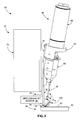
- Fig. 2 shows material feed system 60, X-Y-Z-axis positioning mechanism 70 and base 80 of micro-extrusion system 50 in additional detail.
- the assembly shown in Fig. 2 represents an experimental arrangement utilized to produce solar cells on a small scale, and those skilled in the art will recognize that other arrangements would typically be used to produce solar cells on a larger scale.
- material feed system 60 includes a housing 62 that supports a pneumatic cylinder 64, which is operably coupled to a cartridge 66 such that material is forced from cartridge 66 through feedpipe 68 into printhead assembly 100.
- a pneumatic cylinder 64 which is operably coupled to a cartridge 66 such that material is forced from cartridge 66 through feedpipe 68 into printhead assembly 100.
- X-Y-Z-axis positioning mechanism 70 includes a Z-axis stage 72 that is movable in the Z-axis (vertical) direction relative to target substrate 51 by way of a housing/actuator 74 using known techniques.
- Mounting plate 76 is rigidly connected to a lower end of Z-axis stage 72 and supports printhead assembly 100, and a mounting frame 78 is rigidly connected to and extends upward from Z-axis stage 72 and supports pneumatic cylinder 64 and cartridge 66. Referring to the lower portion of Fig.
- base 80 includes supporting platform 82, which supports target substrate 51 as an X-Y mechanism moves printhead assembly 100 in the X-axis and Y-axis directions (as well as a couple of rotational axes) over the upper surface of substrate 51 utilizing known techniques.
- airflow/gas jet source 90 is fixedly mounted to Z-axis stage 72 such that airflow/gas jet source 90 is held in a fixed relationship relative to extrusion printhead assembly 100 while directing gas 95 onto bead 55.
- airflow/gas jet source 90 may be supported by a structure separate from Z-axis stage 72, although this arrangement may be unnecessarily complicated.
- layered micro-extrusion printhead assembly 100 includes a first (back) plate structure 110, a second (front) plate structure 130, and a layered nozzle structure 150 connected therebetween.
- Back plate structure 110 and front plate structure 130 serve to guide the extrusion material from an inlet port 116 to layered nozzle structure 150, and to rigidly support layered nozzle structure 150 such that extrusion nozzles 163 defined in layered nozzle structure 150 are pointed toward substrate 51 at a predetermined tilted angle ⁇ 1 (e.g., 45°), whereby extruded material traveling down each extrusion nozzle 163 toward its corresponding nozzle orifice 169 is directed toward target substrate 51.
- ⁇ 1 e.g. 45°
- back plate structure 110 and front plate structure 130 includes one or more integrally molded or machined metal parts.
- back plate structure 110 includes an angled back plate 111 and a back plenum 120
- front plate structure 130 includes a single-piece metal plate.
- Angled back plate 111 includes a front surface 112, a side surface 113, and a back surface 114, with front surface 112 and back surface 114 forming a predetermined angle ⁇ 2 (e.g., 45°; shown in Fig. 1 ).
- Angled back plate 111 also defines a bore 115 that extends from a threaded countersunk bore inlet 116 defined in side wall 113 to a bore outlet 117 defined in back surface 114.
- Back plenum 120 includes parallel front surface 122 and back surface 124, and defines a conduit 125 having an inlet 126 defined through front surface 122, and an outlet 127 defined in back surface 124. As described below, bore 115 and plenum 125 cooperate to feed extrusion material to layered nozzle structure 150.
- Front plate structure 130 includes a front surface 132 and a beveled lower surface 134 that form predetermined angle ⁇ 2 (shown in Fig. 1 ).
- Layered nozzle structure 150 includes two or more stacked plates (e.g., a metal such as aluminum, steel or plastic that combine to form one or more extrusion nozzles 163.
- layered nozzle structure 150 includes a top nozzle plate 153, a bottom nozzle plate 156, and a nozzle outlet plate 160 sandwiched between top nozzle plate 153 and bottom nozzle plate 156.
- Top nozzle plate 153 defines an inlet port (through hole) 155, and has a (first) front edge 158-1.
- Bottom nozzle plate 156 is a substantially solid (i.e., continuous) plate having a (third) front edge 158-2.
- Nozzle outlet plate 160 includes a (second)front edge 168 and defines an elongated nozzle channel 162 extending in a predetermined first flow direction F1 from a closed end 165 to an nozzle orifice 169 defined through front edge 168.
- nozzle outlet plate 160 is sandwiched between top nozzle plate 153 and bottom nozzle plate 156 such that elongated nozzle channel 162, a front portion 154 of top nozzle plate 153, and a front portion 157 of bottom nozzle plate 156 combine to define elongated extrusion nozzle 163 that extends from closed end 165 to nozzle orifice 169.
- top nozzle plate 153 is mounted on nozzle outlet plate 160 such that inlet port 155 is aligned with closed end 165 of elongated channel 162, whereby extrusion material forced through inlet port 155 flows in direction F1 along extrusion nozzle 163, and exits from layered nozzle structure 150 by way of nozzle orifice 169 to form bead 55 on substrate 51.
- angled back plate 111 of printhead assembly 100 is rigidly connected to mounting plate 76 by way of one or more fasteners (e.g., machine screws) 142 such that beveled surface 134 of front plate structure 130 is positioned close to parallel to upper surface 52 of target substrate 51.
- fasteners e.g., machine screws
- One or more second fasteners 144 are utilized to connect front plate structure 130 to back plate structure 110 with layered nozzle structure 150 pressed between the back surface of front plate structure 130 and the back surface of back plenum 120.
- material feed system 60 is operably coupled to bore 115 by way of feedpipe 68 and fastener 69 using known techniques, and extrusion material forced into bore 115 is channeled to layered nozzle structure 150 by way of conduit 125.
- a hardenable material is injected into bore 115 and conduit 125 of printhead assembly 100 in the manner described in co-owned and co-pending US Patent Application Serial No. 12/267,147 entitled "DEAD VOLUME REMOVAL FROM AN EXTRUSION PRINTHEAD".
- This hardenable material forms portions 170 that fill any dead zones of conduit 125 that could otherwise trap the extrusion material and lead to clogs.
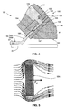
- Fig. 4 is a simplified cross-sectional side view showing a portion of a printhead assembly 100 during operation.
- extrusion material exiting conduit 125 enters the closed end of nozzle 163 by way of inlet 155 and closed end 165 (both shown in Fig. 3 ) of nozzle 163, and flows in direction F1 down nozzle 163 toward outlet 169.
- the extrusion material flowing in the nozzle 163 is directed through the nozzle opening 169.
- a "flying" portion 55A of bead 55 disposed immediately after ejection i.e., before striking upper surface 52 of substrate 51
- a "landed" portion 55B of bead 55 is disposed on upper surface 52 for reasons that are described below.
- the extruded material is guided at the tilted angle ⁇ 2 as it exits nozzle orifice 169, thus being directed toward substrate 51 in a manner that facilitates high volume solar cell production.
- the present invention is specifically directed to techniques for generating an air flow or gas jet onto portion 55A of bead 55 such that bead 55 is reliably deflected down onto substrate 51 as it exits from the dispense nozzle.
- the principal force used to deflect "flying" bead portion 55A is the aerodynamic drag force of the air encountering bead portion 55A in the air flow path. The drag force occurs in the direction of air flow.
- a secondary force that may come into play is the lift force, which will not be considered for the estimates below.
- ⁇ is the density of air
- v is the air velocity
- C d is the drag coefficient
- A is the cross sectional area of the object. Equation 1 is valid when the wake behind an object (e.g., "flying" bead portion 55A) is turbulent.
- a rough estimate of the deflection of bead portion 55A is provided by considering bead portion 55A as an elastic cantilever of length l , thickness t and width w .
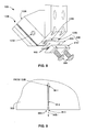
- Fig. 6 is a side view showing a portion of a micro-extrusion system 50A according to a first specific embodiment in which an air knife 90A is utilized to direct a remote air flow (indicated by dashed line 95A) against "flying" bead portion 55A such that bead 55 is reliably forced onto substrate 51 as it emerges from printhead assembly 100.
- Air knife 90A includes a block 91A that is attached to Z-axis stage 72 by way of a bracket 92A such that a curved surface 93A is supported over substrate 51.
- Air knife 90A takes in a flow of compressed air (not shown) and sends the air out through a narrow slot (not shown) located just above curved surface 93A.
- air knife 90A is replaced with a simple wing-like air foil in which curved surface 93A forces air downward and toward printhead assembly 100 as printhead assembly 100 is moved relative to substrate 51.
- Fig. 7 is a side view showing a portion of a micro-extrusion system 50B according to a second specific embodiment in which a pressurized gas (e.g., dry nitrogen) is introduced into a gas jet array 90B from a source (not shown) by way of a pipe 91B, where gas jet array 90B redirects the pressurized gas (e.g., as indicated by dashed-line arrow 95B in Fig. 7 ) onto "flying" portions 55A of each bead 55 while printhead assembly 100B is moved in the Y-axis direction relative to target substrate 51.
- a pressurized gas e.g., dry nitrogen
- printhead assembly 100B is slightly modified from the structures described above in that a back plenum 120B, which otherwise functions as described above is modified to fixedly support gas jet array 90B, and to channel pressurized gas from pipe 91B to the gas jets (described below) provided on gas jet array 90B.
- Fig. 8 is a partial exploded perspective view showing gas jet array 90B and printhead assembly 100B in additional detail.
- back plenum 120B includes a threaded inlet 123B that receives pressurized gas from pipe 91B (see Fig. 7 ).
- the pressurized air passes through a channel (not shown) that communicates with one or more elongated outlets 129B.
- Gas jet array 90B includes a material sheet (e.g., metal or Cirlex, which is a form of polyimide) that is clamped against back surface 128B by way of a back plate structure 97B, with alignment pins being employed to ensure that the air jets are aligned to intersect the nozzle orifices with precise registration.
- material sheet e.g., metal or Cirlex, which is a form of polyimide
- Fig. 9 is an enlarged view showing an exemplary jet nozzle 96B-1 of the array shown in Fig. 9 according to an embodiment of the present invention.
- Jet nozzle 96B-1 receives pressurized gas from elongated opening 129B at its closed end 96-1, and includes a converging/diverging neck region 96-2 between closed end 96-1 and outlet opening 96-3, from which an associated air jet portion 95B-1 is emitted.
- This converging/diverging architecture serves to collimate the exiting flow of air.
- Fig. 10 is an exploded perspective view showing a portion of a micro-extrusion system 50C including a plenum 120C and a gas jet array 90C according to yet another embodiment of the present invention. Similar to the embodiment described above, pressurized air enters through an opening 123C and passes through a channel (not shown) that communicates with elongated outlets 129C-1 and 129C-2.
- gas jet array 90B includes a jet assembly 95C including a spacer layer 95C-1, a nozzle pair array layer 95C-2, and a connecting channel layer 95C-3 that are clamped against surface 128C of back plenum 120C by way of a clamp suture 97C.
- Gas jet array 90B also differs from the embodiment described above with reference to Figs. 7 and 8 in that associated pairs of air jets 96C are directed at each nozzle opening (not shown) in order to provide controllable sideways deflection and torsional deflection of the extruded bead.
- Air jet pairs 96C are formed on a nozzle pair array layer (metal sheet) 95C-2, which is sandwiched between a spacer layer 95C-1 and a connecting channel layer 95C-2.
- pressurized gas is supplied to a first jet of each jet nozzle pair 96C by way of outlet 129B-1 and opening 99-11 defined in spacer layer 95C-1, and to the second jet of each jet nozzle pair 96C by way of outlet 129B-2, opening 99-12 defined in spacer layer 95C-1, opening 99-22 defined in nozzle pair array layer 95C-2, and vertical slots 98 defined in connecting channel layer 95C-2.
- Fig. 11 is a simplified side view showing a portion of a micro-extrusion system 50D according to another embodiment of the present invention.
- Micro-extrusion system 50D includes a Z-axis positioning mechanism 70D and printhead assembly 100 and other features similar to those described above, but differs in that it also includes a gas jet array 90D that is mounted onto Z-axis positioning mechanism 70D such that gas jet array 90D directs pressurized gas (e.g., air, dry nitrogen, or other gas phase fluid) 95D downward onto a portion 55B of extruded beads (lines) 55 immediately after portion 55B has contacted upper surface 52 of target substrate 51 (i.e., while the extruded material is still "wet").
- pressurized gas e.g., air, dry nitrogen, or other gas phase fluid
- Gas jet array 90D includes clamp portions 98D-1 and 98D-2 disposed on opposite sides of one or more metal air jet plates 95D that are formed similar to the air jet arrangements described above with reference to Figs. 8 and 10 , and are secured to Z-axis positioning mechanism 70D by way of screws 99D.
- back clamp portion 98D-2 includes a threaded inlet 93D that receives pressurized gas by way of a pipe 91D.
- the pressurized gas passes through a channel (not shown) that communicates with one or more elongated nozzle outlets 96D.
- pressurized gas 95D applies sufficient force to flatten (slump) portion 55B toward substrate surface 52, thereby facilitating the formation of wide and flat lines of material using a relatively narrow and tall extrusion nozzles.
- a single bead can be expanded to many times its deposited width.
- the inventors have found it possible to flatten (slump) extrusion material lines 55 from a width of about 0.4 mm to a width of greater than 2 mm and a wet thickness of 0.010 to 0.020 mm.
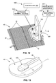
- micro-extrusion system 50D includes a controller 200 (e.g., a microprocessor) that is programmed to both a control extrusion material source 60D to facilitate selective extrusion of material onto substrate 41 by way of printhead 100, and one or more high speed valves 210 that is coupled to a pressurized gas source 220 to selectively control the generation of gas jets by way of gas jet array 90D.
- controller 200 e.g., a microprocessor
- high speed valves 210 are used to pulse the gas pressure at selected times to produce flattening of selected sections of the extruded material structures (lines).
- Fig. 13 is an enlarged partial perspective view showing a gridline endpoint 44A of an H-pattern solar cell 40 that is flattened (slumped) according to an embodiment of the present invention utilizing the arrangement shown in Fig. 12 .
- Adherence of gridlines 44 can be enhanced by increasing the contact area of endpoints 44A. It is an aspect of this invention that gas jets are used to actively slump endpoints 44A of gridlines 44 to create larger contact areas.
- extrusion material source 60D is actuated using control signals sent from controller 200 according to known techniques to begin extruding gridline material on substrate 41.
- controller 300 sends an actuation control signal to high speed valve 210, causing high speed valve 210 to open briefly to pass a pulse (short burst) of high pressure gas from pressurized gas source 220 that coincides with the proper positioning of endpoints 44A under the gas jets, thereby producing the flattening (slumping) shown in Fig. 13 .
- the gas jet assisted slumping described above is utilized to flatten out the topography on buss bars 45 at the vertices between buss bars 45 and gridlines 44.
- system 50D (see Fig. 12 ) is utilized in the manner described above to generate pulses of pressurized gas between times T3 and T4, coinciding with the positioning of the gas jet array over sections 44B of each gridline 44 (i.e., a portion that is located on buss bar 45).
- the gas pulses are delivered onto the buss bar-gridline vertices in order to flatten out the topography (i.e., such that the uppermost surface of section 44B is substantially equal to the upper surface of "unslumped" sections 44-1 and 44-2) while the extruded gridline material (ink) is in a wet state. This way, undesirable slumping of gridlines 44 in the broad area of the cell is avoided.
- Fig. 15 is a partial perspective view showing an alternative gridline flattening operation in which substrate 41 is turned after gridlines 44 are printed (i.e., such that the Y-axis traveling direction of printhead assembly 100 is parallel to buss lines 45), and only the gas jets located over buss lines 45 are actuated, thereby producing a desired flattened topography similar to that shown in Fig. 14 .
- an alternative gridline flattening operation similar to that described above is used to produce back surface features using the extrusion techniques described above (i.e., as opposed to conventional screen printing techniques).
- the target thickness for the back side metallization is in the range of .005 to .030 mm thick after firing.
- the back surface structure e.g., similar to that shown in Fig. 16(B)
- the separate beads of silver and aluminum are deposited by extrusion printing.
- the beads of silver and aluminum ink are deposited on a single co-extrusion printing apparatus capable of printing both aluminum and silver inks simultaneously, obviating the need for two separate printers and an intervening drying step as is currently practiced.
- the various gas jet arrangements described above are used in combination with single extrusion and co-extrusion printhead assemblies with directional extruded bead control, such as those described in co-owned and co-pending U.S. Patent Application Serial No. 12/267,069 , entitled "DIRECTIONAL EXTRUDED BEAD CONTROL".
- one or more of the above-described embodiments may be enhanced using an arrangement in which the bead of ink includes a material that can be attracted by electrostatic force to the substrate.
- the voltage V is limited by the breakdown strength of air (3 kV/mm) to about 1000 Volts. Deflections on the order of 10 nm are feasible with this level of electrostatic actuation.
- a spacer may be placed between the air jet nozzle and the printhead facet in order to reduce dispersive drag on the air jet.
Landscapes
- Engineering & Computer Science (AREA)
- Mechanical Engineering (AREA)
- Coating Apparatus (AREA)
- Application Of Or Painting With Fluid Materials (AREA)
- Processing And Handling Of Plastics And Other Materials For Molding In General (AREA)
Abstract
Description
- The present invention relates to an improvement in micro-extrusion systems. The following description is presented to enable one of ordinary skill in the art to make and use the invention as provided in the context of a particular application and its requirements. As used herein, directional terms such as "upper", "top", "lower", "bottom", "front", "rear", and "lateral" are intended to provide relative positions for purposes of description, and are not intended to designate an absolute frame of reference. Various modifications to the preferred embodiment will be apparent to those with skill in the art, and the general principles defined herein may be applied to other embodiments. Therefore, the present invention is not intended to be limited to the particular embodiments shown and described, but is to be accorded the widest scope consistent with the principles and novel features herein disclosed.
-
Fig. 1 is a simplified side view showing a portion of a generalizedmicro-extrusion system 50 for forming parallel extrudedmaterial lines 55 onupper surface 52 of asubstrate 51.Micro-extrusion system 50 includes anextrusion printhead assembly 100 that is operably coupled to amaterial feed system 60 by way of at least onefeedpipe 68 and an associatedfastener 69. The materials are applied through pushing and/or drawing techniques (e.g., hot and cold) in which the materials are pushed (e.g., squeezed, etc.) and/or drawn (e.g., via a vacuum, etc.) throughextrusion printhead assembly 100, and out one or more outlet orifices (nozzle openings) 169 that are respectively defined in a lower portion ofprinthead assembly 100.Micro-extrusion system 50 also includes a X-Y-Z-axis positioning mechanism 70 including amounting plate 76 for rigidly supporting and positioningprinthead assembly 100 relative tosubstrate 51, and abase 80 including aplatform 82 for supportingsubstrate 51 in a stationary position asprinthead assembly 100 is moved in a predetermined (e.g., Y-axis) direction oversubstrate 51. In alternative embodiment (not shown),printhead assembly 100 is stationary andbase 80 includes an X-Y axis positioning mechanism for movingsubstrate 51 underprinthead assembly 100. - In accordance with the present invention,
micro-extrusion system 50 also includes an airflow/gas jet source 90 that is positioned downstream fromnozzle openings 169 and served to direct a gas 95 (e.g., air or dry nitrogen) either ontobeads 55 immediately after leaving printhead assembly 100 (i.e.,portion 55A located betweennozzle opening 169 and substrate 51), or immediately afterbeads 55 have landed on substrate 51 (i.e.,portion 55B located on substrate 51). As described in additional detail below, in bothcases gas 95 serves to pushbeads 55 towardsubstrate 51, thereby either addressing the bead direction problem mentioned above by pushingbeads 55 towardsubstrate 51, or byflattening beads 55 against thesubstrate surface 52 using pressurized gas. -
Fig. 2 showsmaterial feed system 60, X-Y-Z-axis positioning mechanism 70 andbase 80 ofmicro-extrusion system 50 in additional detail. The assembly shown inFig. 2 represents an experimental arrangement utilized to produce solar cells on a small scale, and those skilled in the art will recognize that other arrangements would typically be used to produce solar cells on a larger scale. Referring to the upper right portion ofFig. 2 ,material feed system 60 includes ahousing 62 that supports apneumatic cylinder 64, which is operably coupled to acartridge 66 such that material is forced fromcartridge 66 throughfeedpipe 68 intoprinthead assembly 100. Referring to the left side ofFig. 2 , X-Y-Z-axis positioning mechanism 70 includes a Z-axis stage 72 that is movable in the Z-axis (vertical) direction relative totarget substrate 51 by way of a housing/actuator 74 using known techniques.Mounting plate 76 is rigidly connected to a lower end of Z-axis stage 72 and supportsprinthead assembly 100, and amounting frame 78 is rigidly connected to and extends upward from Z-axis stage 72 and supportspneumatic cylinder 64 andcartridge 66. Referring to the lower portion ofFig. 2 ,base 80 includes supportingplatform 82, which supportstarget substrate 51 as an X-Y mechanism movesprinthead assembly 100 in the X-axis and Y-axis directions (as well as a couple of rotational axes) over the upper surface ofsubstrate 51 utilizing known techniques. - Referring to the lower portion of
Fig. 2 , in accordance with an embodiment of the present invention, airflow/gas jet source 90 is fixedly mounted to Z-axis stage 72 such that airflow/gas jet source 90 is held in a fixed relationship relative toextrusion printhead assembly 100 while directinggas 95 ontobead 55. In an alternative embodiment (not shown), airflow/gas jet source 90 may be supported by a structure separate from Z-axis stage 72, although this arrangement may be unnecessarily complicated. - As shown in
Fig. 1 and in exploded form inFig. 3 , layeredmicro-extrusion printhead assembly 100 includes a first (back)plate structure 110, a second (front)plate structure 130, and alayered nozzle structure 150 connected therebetween.Back plate structure 110 andfront plate structure 130 serve to guide the extrusion material from aninlet port 116 to layerednozzle structure 150, and to rigidly support layerednozzle structure 150 such thatextrusion nozzles 163 defined inlayered nozzle structure 150 are pointed towardsubstrate 51 at a predetermined tilted angle θ1 (e.g., 45°), whereby extruded material traveling down eachextrusion nozzle 163 toward itscorresponding nozzle orifice 169 is directed towardtarget substrate 51. - Each of
back plate structure 110 andfront plate structure 130 includes one or more integrally molded or machined metal parts. In the disclosed embodiment,back plate structure 110 includes anangled back plate 111 and aback plenum 120, andfront plate structure 130 includes a single-piece metal plate. Angledback plate 111 includes afront surface 112, aside surface 113, and aback surface 114, withfront surface 112 andback surface 114 forming a predetermined angle θ2 (e.g., 45°; shown inFig. 1 ). Angledback plate 111 also defines abore 115 that extends from a threadedcountersunk bore inlet 116 defined inside wall 113 to a bore outlet 117 defined inback surface 114.Back plenum 120 includesparallel front surface 122 andback surface 124, and defines aconduit 125 having aninlet 126 defined throughfront surface 122, and anoutlet 127 defined inback surface 124. As described below, bore 115 andplenum 125 cooperate to feed extrusion material to layerednozzle structure 150.Front plate structure 130 includes afront surface 132 and a beveledlower surface 134 that form predetermined angle θ2 (shown inFig. 1 ). - Layered
nozzle structure 150 includes two or more stacked plates (e.g., a metal such as aluminum, steel or plastic that combine to form one ormore extrusion nozzles 163. In the embodiment shown inFig. 3 , layerednozzle structure 150 includes atop nozzle plate 153, abottom nozzle plate 156, and anozzle outlet plate 160 sandwiched betweentop nozzle plate 153 andbottom nozzle plate 156.Top nozzle plate 153 defines an inlet port (through hole) 155, and has a (first) front edge 158-1.Bottom nozzle plate 156 is a substantially solid (i.e., continuous) plate having a (third) front edge 158-2.Nozzle outlet plate 160 includes a (second)front edge 168 and defines anelongated nozzle channel 162 extending in a predetermined first flow direction F1 from a closedend 165 to annozzle orifice 169 defined throughfront edge 168. When operably assembled (e.g., as shown inFig. 4 ),nozzle outlet plate 160 is sandwiched betweentop nozzle plate 153 andbottom nozzle plate 156 such thatelongated nozzle channel 162, afront portion 154 oftop nozzle plate 153, and afront portion 157 ofbottom nozzle plate 156 combine to defineelongated extrusion nozzle 163 that extends from closedend 165 tonozzle orifice 169. In addition,top nozzle plate 153 is mounted onnozzle outlet plate 160 such thatinlet port 155 is aligned with closedend 165 ofelongated channel 162, whereby extrusion material forced throughinlet port 155 flows in direction F1 alongextrusion nozzle 163, and exits fromlayered nozzle structure 150 by way ofnozzle orifice 169 to formbead 55 onsubstrate 51. - Referring again to
Fig. 1 , when operably assembled and mounted ontomicro-extrusion system 50, angledback plate 111 ofprinthead assembly 100 is rigidly connected tomounting plate 76 by way of one or more fasteners (e.g., machine screws) 142 such thatbeveled surface 134 offront plate structure 130 is positioned close to parallel toupper surface 52 oftarget substrate 51. One or moresecond fasteners 144 are utilized to connectfront plate structure 130 toback plate structure 110 withlayered nozzle structure 150 pressed between the back surface offront plate structure 130 and the back surface ofback plenum 120. In addition,material feed system 60 is operably coupled to bore 115 by way offeedpipe 68 and fastener 69 using known techniques, and extrusion material forced intobore 115 is channeled to layerednozzle structure 150 by way ofconduit 125. - In a preferred embodiment, as shown in
Fig. 1 , a hardenable material is injected intobore 115 andconduit 125 ofprinthead assembly 100 in the manner described in co-owned and co-pendingUS Patent Application Serial No. 12/267,147 entitled "DEAD VOLUME REMOVAL FROM AN EXTRUSION PRINTHEAD". This hardenable material formsportions 170 that fill any dead zones ofconduit 125 that could otherwise trap the extrusion material and lead to clogs. -
Fig. 4 is a simplified cross-sectional side view showing a portion of aprinthead assembly 100 during operation. As shown inFig. 4 , extrusionmaterial exiting conduit 125 enters the closed end ofnozzle 163 by way ofinlet 155 and closed end 165 (both shown inFig. 3 ) ofnozzle 163, and flows in direction F1 downnozzle 163 towardoutlet 169. Referring toFig. 4 , the extrusion material flowing in thenozzle 163 is directed through the nozzle opening 169. As described herein, a "flying"portion 55A ofbead 55 disposed immediately after ejection (i.e., before strikingupper surface 52 of substrate 51) is identified separately from a "landed"portion 55B ofbead 55 is disposed onupper surface 52 for reasons that are described below. Referring back toFig. 1 , the extruded material is guided at the tilted angle θ2 as it exitsnozzle orifice 169, thus being directed towardsubstrate 51 in a manner that facilitates high volume solar cell production. - According to a first series of embodiments, the present invention is specifically directed to techniques for generating an air flow or gas jet onto
portion 55A ofbead 55 such thatbead 55 is reliably deflected down ontosubstrate 51 as it exits from the dispense nozzle. Referring toFig. 5 , the principal force used to deflect "flying"bead portion 55A is the aerodynamic drag force of the air encounteringbead portion 55A in the air flow path. The drag force occurs in the direction of air flow. A secondary force that may come into play is the lift force, which will not be considered for the estimates below. A rough approximation of the drag force Fd on a object is expressed as set in Equation 1:
equation 1, ρ is the density of air, v is the air velocity, Cd is the drag coefficient, and A is the cross sectional area of the object.Equation 1 is valid when the wake behind an object (e.g., "flying"bead portion 55A) is turbulent. A rough estimate of the deflection ofbead portion 55A is provided by consideringbead portion 55A as an elastic cantilever of length l, thickness t and width w. In this case the spring constant k of thebead portion 55A as it pokes out from the nozzle orifice may be expressed by Equation 2:
where Y is the elastic modulus ofbead portion 55A, which is on the order of 1000 Pa. Typical bead width and thickness are 250 and 100 microns, respectively. If one desires to deflectbead portion 55A by 50 microns as it emerges by 100 microns from the nozzle orifice, the above relations provide an estimate that an air velocity on the order of 10 m/sec is required. This level of air flow is readily achieved with modest air pressures and easily fabricated air delivery apparatus, examples of which are provided below. -
Fig. 6 is a side view showing a portion of amicro-extrusion system 50A according to a first specific embodiment in which anair knife 90A is utilized to direct a remote air flow (indicated by dashed line 95A) against "flying"bead portion 55A such thatbead 55 is reliably forced ontosubstrate 51 as it emerges fromprinthead assembly 100.Air knife 90A includes ablock 91A that is attached to Z-axis stage 72 by way of abracket 92A such that acurved surface 93A is supported oversubstrate 51.Air knife 90A takes in a flow of compressed air (not shown) and sends the air out through a narrow slot (not shown) located just abovecurved surface 93A. The air stream coming out of the slot suck in additional ambient air asblock 91A is moved relative to the upper surface ofsubstrate 51 in the Y-axis direction, and directs the air towardprinthead assembly 100, thereby directing a desired air flow 95A onto "flying"portions 55A of each saidbead 55. In one embodiment,air knife 90A is replaced with a simple wing-like air foil in whichcurved surface 93A forces air downward and towardprinthead assembly 100 asprinthead assembly 100 is moved relative tosubstrate 51. -
Fig. 7 is a side view showing a portion of amicro-extrusion system 50B according to a second specific embodiment in which a pressurized gas (e.g., dry nitrogen) is introduced into agas jet array 90B from a source (not shown) by way of apipe 91B, wheregas jet array 90B redirects the pressurized gas (e.g., as indicated by dashed-line arrow 95B inFig. 7 ) onto "flying"portions 55A of eachbead 55 whileprinthead assembly 100B is moved in the Y-axis direction relative totarget substrate 51. In the disclosed embodiment,printhead assembly 100B is slightly modified from the structures described above in that aback plenum 120B, which otherwise functions as described above is modified to fixedly supportgas jet array 90B, and to channel pressurized gas frompipe 91B to the gas jets (described below) provided ongas jet array 90B. -
Fig. 8 is a partial exploded perspective view showinggas jet array 90B andprinthead assembly 100B in additional detail. As indicated,back plenum 120B includes a threadedinlet 123B that receives pressurized gas frompipe 91B (seeFig. 7 ). The pressurized air passes through a channel (not shown) that communicates with one or moreelongated outlets 129B.Gas jet array 90B includes a material sheet (e.g., metal or Cirlex, which is a form of polyimide) that is clamped againstback surface 128B by way of aback plate structure 97B, with alignment pins being employed to ensure that the air jets are aligned to intersect the nozzle orifices with precise registration. Note that the direction of air flow leaving the jets is at a large angle relative to the direction of ink flow leaving the printhead, which helps to ensure that the drag force is maximized. This arrangement has the advantage that less gas is used, and less gas flow is directed onto the substrate (not shown), since air flow under the bead can prevent the bead from landing on and sticking to the substrate. -
Fig. 9 is an enlarged view showing anexemplary jet nozzle 96B-1 of the array shown inFig. 9 according to an embodiment of the present invention.Jet nozzle 96B-1 receives pressurized gas fromelongated opening 129B at its closed end 96-1, and includes a converging/diverging neck region 96-2 between closed end 96-1 and outlet opening 96-3, from which an associatedair jet portion 95B-1 is emitted. This converging/diverging architecture serves to collimate the exiting flow of air. -
Fig. 10 is an exploded perspective view showing a portion of a micro-extrusion system 50C including aplenum 120C and agas jet array 90C according to yet another embodiment of the present invention. Similar to the embodiment described above, pressurized air enters through anopening 123C and passes through a channel (not shown) that communicates withelongated outlets 129C-1 and 129C-2. In this embodiment,gas jet array 90B includes ajet assembly 95C including aspacer layer 95C-1, a nozzlepair array layer 95C-2, and a connectingchannel layer 95C-3 that are clamped againstsurface 128C ofback plenum 120C by way of aclamp suture 97C.Gas jet array 90B also differs from the embodiment described above with reference toFigs. 7 and8 in that associated pairs ofair jets 96C are directed at each nozzle opening (not shown) in order to provide controllable sideways deflection and torsional deflection of the extruded bead. Air jet pairs 96C are formed on a nozzle pair array layer (metal sheet) 95C-2, which is sandwiched between aspacer layer 95C-1 and a connectingchannel layer 95C-2. During operation, pressurized gas is supplied to a first jet of eachjet nozzle pair 96C by way ofoutlet 129B-1 and opening 99-11 defined inspacer layer 95C-1, and to the second jet of eachjet nozzle pair 96C by way ofoutlet 129B-2, opening 99-12 defined inspacer layer 95C-1, opening 99-22 defined in nozzlepair array layer 95C-2, andvertical slots 98 defined in connectingchannel layer 95C-2. -
Fig. 11 is a simplified side view showing a portion of amicro-extrusion system 50D according to another embodiment of the present invention.Micro-extrusion system 50D includes a Z-axis positioning mechanism 70D andprinthead assembly 100 and other features similar to those described above, but differs in that it also includes agas jet array 90D that is mounted onto Z-axis positioning mechanism 70D such thatgas jet array 90D directs pressurized gas (e.g., air, dry nitrogen, or other gas phase fluid) 95D downward onto aportion 55B of extruded beads (lines) 55 immediately afterportion 55B has contactedupper surface 52 of target substrate 51 (i.e., while the extruded material is still "wet").Gas jet array 90D includesclamp portions 98D-1 and 98D-2 disposed on opposite sides of one or more metalair jet plates 95D that are formed similar to the air jet arrangements described above with reference toFigs. 8 and10 , and are secured to Z-axis positioning mechanism 70D by way ofscrews 99D. As indicated,back clamp portion 98D-2 includes a threadedinlet 93D that receives pressurized gas by way of apipe 91D. The pressurized gas passes through a channel (not shown) that communicates with one or moreelongated nozzle outlets 96D. By directingpressurized gas 95D downward ontoportion 55B,system 50D facilitates the high throughput printing of thin, low aspect ratio lines 55 onsubstrate 51. That is,pressurized gas 95D applies sufficient force to flatten (slump)portion 55B towardsubstrate surface 52, thereby facilitating the formation of wide and flat lines of material using a relatively narrow and tall extrusion nozzles. With this technique, a single bead can be expanded to many times its deposited width. For example, with this arrangement, the inventors have found it possible to flatten (slump)extrusion material lines 55 from a width of about 0.4 mm to a width of greater than 2 mm and a wet thickness of 0.010 to 0.020 mm. With the loading and viscosity of the ink used for extrusion printing it would be impossible to produce lines of these dimensions directly, even by allowing large amounts of time for the ink to slump under gravitational and wetting forces (in this regard, a practical consideration is that standard production flow between the printing of buss bars 45 and the printing ofgridlines 44 only allows about three seconds or less between the buss bar print and the grid line print). In addition, as set forth below, this technique is selectively utilized to create reliable connections between the gridline endpoints and the substrate in H-pattern solar cells, and is also utilized to selectively flatten the cell topography to facilitate stronger solder joints between buss bars and metal ribbons. -
Fig. 12 is a modified perspective view showing a portion ofmicro-extrusion system 50D during operation in the production of an H-patternsolar cell 40 similar to that described above in the background section. According to another aspect of the present invention,micro-extrusion system 50D includes a controller 200 (e.g., a microprocessor) that is programmed to both a controlextrusion material source 60D to facilitate selective extrusion of material ontosubstrate 41 by way ofprinthead 100, and one or morehigh speed valves 210 that is coupled to apressurized gas source 220 to selectively control the generation of gas jets by way ofgas jet array 90D. As described below,high speed valves 210 are used to pulse the gas pressure at selected times to produce flattening of selected sections of the extruded material structures (lines). -
Fig. 13 is an enlarged partial perspective view showing agridline endpoint 44A of an H-patternsolar cell 40 that is flattened (slumped) according to an embodiment of the present invention utilizing the arrangement shown inFig. 12 . Adherence ofgridlines 44 can be enhanced by increasing the contact area ofendpoints 44A. It is an aspect of this invention that gas jets are used to actively slumpendpoints 44A ofgridlines 44 to create larger contact areas. In this regard, as theprinthead assembly 100 passes oversubstrate 41 in the manner shown inFig. 12 ,extrusion material source 60D is actuated using control signals sent fromcontroller 200 according to known techniques to begin extruding gridline material onsubstrate 41. During a time period between time T1 and time T2 (i.e., a moment later whengas jet array 90D has moved in the Y-axis direction overendpoints 44A), controller 300 sends an actuation control signal tohigh speed valve 210, causinghigh speed valve 210 to open briefly to pass a pulse (short burst) of high pressure gas frompressurized gas source 220 that coincides with the proper positioning ofendpoints 44A under the gas jets, thereby producing the flattening (slumping) shown inFig. 13 . - In accordance with another embodiment of the present invention, the gas jet assisted slumping described above is utilized to flatten out the topography on buss bars 45 at the vertices between buss bars 45 and
gridlines 44. Referring toFig. 14 ,system 50D (seeFig. 12 ) is utilized in the manner described above to generate pulses of pressurized gas between times T3 and T4, coinciding with the positioning of the gas jet array oversections 44B of each gridline 44 (i.e., a portion that is located on buss bar 45). As mentioned above, by mountinggas jet array 90D immediately behindprinthead assembly 100, the gas pulses are delivered onto the buss bar-gridline vertices in order to flatten out the topography (i.e., such that the uppermost surface ofsection 44B is substantially equal to the upper surface of "unslumped" sections 44-1 and 44-2) while the extruded gridline material (ink) is in a wet state. This way, undesirable slumping ofgridlines 44 in the broad area of the cell is avoided. -
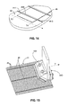
Fig. 15 is a partial perspective view showing an alternative gridline flattening operation in whichsubstrate 41 is turned aftergridlines 44 are printed (i.e., such that the Y-axis traveling direction ofprinthead assembly 100 is parallel to buss lines 45), and only the gas jets located overbuss lines 45 are actuated, thereby producing a desired flattened topography similar to that shown inFig. 14 . - According to another embodiment, an alternative gridline flattening operation similar to that described above is used to produce back surface features using the extrusion techniques described above (i.e., as opposed to conventional screen printing techniques). The target thickness for the back side metallization is in the range of .005 to .030 mm thick after firing. According to an embodiment of the present invention, the back surface structure (e.g., similar to that shown in
Fig. 16(B) ) is produced by first depositing many separate beads of silver and aluminum paste, and then using one or more gas jets or gas curtains to slump and merge the beads together on the substrate to produce a connected structure. In the preferred embodiment, the separate beads of silver and aluminum are deposited by extrusion printing. In the preferred embodiment, the beads of silver and aluminum ink are deposited on a single co-extrusion printing apparatus capable of printing both aluminum and silver inks simultaneously, obviating the need for two separate printers and an intervening drying step as is currently practiced. - In accordance with a preferred embodiment, the various gas jet arrangements described above are used in combination with single extrusion and co-extrusion printhead assemblies with directional extruded bead control, such as those described in co-owned and co-pending
U.S. Patent Application Serial No. 12/267,069 , entitled "DIRECTIONAL EXTRUDED BEAD CONTROL". - In an alternative embodiment, one or more of the above-described embodiments may be enhanced using an arrangement in which the bead of ink includes a material that can be attracted by electrostatic force to the substrate. By applying a voltage V between the substrate and the printhead assembly across a printhead separation d, a bead of ink of width w and
length 1 will experience a force F expressed by Equation 3:
where εo is the air gap (vacuum) permittivity. The voltage V is limited by the breakdown strength of air (3 kV/mm) to about 1000 Volts. Deflections on the order of 10 nm are feasible with this level of electrostatic actuation. - Although the present invention has been described with respect to certain specific embodiments, it will be clear to those skilled in the art that the inventive features of the present invention are applicable to other embodiments as well, all of which are intended to fall within the scope of the present invention. For example, a spacer may be placed between the air jet nozzle and the printhead facet in order to reduce dispersive drag on the air jet.
Claims (12)
- A micro-extrusion system for producing a plurality of beads of extrusion material on an upper surface of a target substrate, the micro-extrusion system comprising:an extrusion printhead assembly including an inlet port, a plurality of nozzle openings, and one or more flow channels, each of the one or more flow channels communicating between said inlet port and an associated one of said plurality of nozzle openings;a material feed system for supplying said extrusion material to said inlet port such that said extrusion material is forced through said one or more flow channels and exits through said plurality of nozzle openings, thereby producing said plurality of beads of extrusion material;means for supporting the extrusion printhead assembly and said target substrate, and for moving the extrusion printhead assembly relative to said target substrate such that extrusion material exiting said plurality of nozzle openings causes said plurality of beads to form parallel lines of extrusion material on the upper surface of the target substrate; andmeans for directing a gas against said plurality of beads such that said gas pushes said plurality of beads toward the target substrate.
- The micro-extrusion system according to Claim 1, wherein said means for directing said gas against said plurality of beads comprises means for directing a pressurized gas against each said bead.
- The micro-extrusion system according to Claim 2,
wherein said means for supporting the extrusion printhead assembly comprises a Z-axis positioning mechanism, and
wherein said means for directing said pressurized gas against each said bead is fixedly connected to said Z-axis positioning mechanism. - The micro-extrusion system according to Claim 2, wherein said means for directing said pressurized gas against each said bead comprises means for directing said pressurized gas against a portion of said each bead that is disposed on the target substrate, whereby said portion is flattened against said substrate.
- The micro-extrusion system according to Claim 1, wherein said means for directing said gas against said plurality of beads comprises means for directing said gas against portions of said plurality of beads that are disposed on the target substrate, whereby said portions are flattened toward said substrate.
- The micro-extrusion system according to Claim 5, wherein said means for directing said gas against portions of said plurality of beads that are disposed on the target substrate comprises means for selectively applying a pressurized gas against said portions.
- The micro-extrusion system according to Claim 6, wherein said means for selectively applying a pressurized gas comprises a high speed valve.
- A method for extruding an extrusion material on an upper surface of a target substrate, the method comprising:supplying said extrusion material to an inlet port of an extrusion printhead assembly having a plurality of nozzle openings and one or more flow channels arranged such that each of the one or more of flow channels communicates between said inlet port and an associated one of said plurality of nozzle openings;, wherein said extrusion material is supplied to said inlet port inlet port such that said extrusion material is forced through said one or more of flow channels and exits through said plurality of nozzle openings, thereby producing a plurality of beads of said extrusion material;supporting the extrusion printhead assembly and said target substrate, and moving the extrusion printhead assembly relative to said target substrate such that extrusion material exiting said plurality of nozzle openings causes said plurality of beads to form parallel lines of extrusion material on the upper surface of the target substrate; anddirecting a gas against said plurality of lines such that said gas pushes said plurality of lines toward the target substrate.
- The method according to Claim 8, directing said gas comprises directing said gas onto a portion of each said bead that is disposed on the target substrate, whereby said portion is flattened toward said substrate.
- The method according to Claim 9, wherein directing said gas onto said portion of each said bead comprises controlling a high speed valve to selectively apply said gas on selected regions of said portion.
- The method according to Claim 10, wherein controlling the high speed valve comprises causing said gas to flatten end points of each of said plurality of lines.
- The method according to Claim 10, wherein controlling the high speed valve comprises causing said gas to flatten selected central sections of said plurality of lines.
Applications Claiming Priority (1)
| Application Number | Priority Date | Filing Date | Title |
|---|---|---|---|
| US12/267,223 US20100117254A1 (en) | 2008-11-07 | 2008-11-07 | Micro-Extrusion System With Airjet Assisted Bead Deflection |
Publications (2)
| Publication Number | Publication Date |
|---|---|
| EP2184767A2 true EP2184767A2 (en) | 2010-05-12 |
| EP2184767A3 EP2184767A3 (en) | 2012-01-25 |
Family
ID=41718349
Family Applications (1)
| Application Number | Title | Priority Date | Filing Date |
|---|---|---|---|
| EP09173595A Withdrawn EP2184767A3 (en) | 2008-11-07 | 2009-10-21 | Micro-extrusion system with airjet assisted bead deflection |
Country Status (5)
| Country | Link |
|---|---|
| US (2) | US20100117254A1 (en) |
| EP (1) | EP2184767A3 (en) |
| JP (1) | JP2010110756A (en) |
| KR (1) | KR20100051556A (en) |
| CN (1) | CN101733231B (en) |
Cited By (1)
| Publication number | Priority date | Publication date | Assignee | Title |
|---|---|---|---|---|
| DE102024128846A1 (en) * | 2024-10-07 | 2026-04-09 | HighLine Technology GmbH | Printhead and its use |
Families Citing this family (16)
| Publication number | Priority date | Publication date | Assignee | Title |
|---|---|---|---|---|
| US20100118081A1 (en) * | 2008-11-07 | 2010-05-13 | Palo Alto Research Center Incorporated | Dead Volume Removal From An Extrusion Printhead |
| US8080729B2 (en) * | 2008-11-24 | 2011-12-20 | Palo Alto Research Center Incorporated | Melt planarization of solar cell bus bars |
| US8960120B2 (en) * | 2008-12-09 | 2015-02-24 | Palo Alto Research Center Incorporated | Micro-extrusion printhead with nozzle valves |
| US8586129B2 (en) * | 2010-09-01 | 2013-11-19 | Solarworld Innovations Gmbh | Solar cell with structured gridline endpoints and vertices |
| US9120190B2 (en) | 2011-11-30 | 2015-09-01 | Palo Alto Research Center Incorporated | Co-extruded microchannel heat pipes |
| US10371468B2 (en) | 2011-11-30 | 2019-08-06 | Palo Alto Research Center Incorporated | Co-extruded microchannel heat pipes |
| US8875653B2 (en) | 2012-02-10 | 2014-11-04 | Palo Alto Research Center Incorporated | Micro-extrusion printhead with offset orifices for generating gridlines on non-square substrates |
| GB201300483D0 (en) * | 2013-01-11 | 2013-02-27 | Zephyros Inc | Extrusion of bands of material |
| US10537913B2 (en) * | 2013-04-29 | 2020-01-21 | Hewlett-Packard Development Company, L.P. | Selective slot coating |
| TW201505198A (en) * | 2013-07-19 | 2015-02-01 | 斯克林集團公司 | Pattern forming device and pattern forming method |
| US10800086B2 (en) * | 2013-08-26 | 2020-10-13 | Palo Alto Research Center Incorporated | Co-extrusion of periodically modulated structures |
| DE102019122131B4 (en) * | 2019-08-16 | 2021-06-10 | Fraunhofer-Gesellschaft zur Förderung der angewandten Forschung e.V. | Method and apparatus for parallel extrusion of printing medium onto a substrate |
| JP7593741B2 (en) | 2020-03-26 | 2024-12-03 | ノードソン コーポレーション | Nozzle, adhesive application head, adhesive application device, and diaper manufacturing method |
| CN112014193B (en) * | 2020-07-24 | 2021-06-15 | 武汉大学中南医院 | A Novel FJ Dyeing Method and Device |
| CN117019433A (en) * | 2023-07-07 | 2023-11-10 | 惠州旋旋科技有限公司 | fluid injection device |
| KR20250078208A (en) * | 2023-11-24 | 2025-06-02 | 삼성에스디아이 주식회사 | Rechargeable battery electrode manufacturing slot die and rechargeable battery electrode and manufacturing method using the same |
Family Cites Families (113)
| Publication number | Priority date | Publication date | Assignee | Title |
|---|---|---|---|---|
| US655739A (en) * | 1900-02-26 | 1900-08-14 | Henry Runtz | Display device for neckties. |
| US2031387A (en) * | 1934-08-22 | 1936-02-18 | Schwarz Arthur | Nozzle |
| US2789731A (en) * | 1955-06-06 | 1957-04-23 | Leonard L Marraffino | Striping dispenser |
| US3032008A (en) * | 1956-05-07 | 1962-05-01 | Polaroid Corp | Apparatus for manufacturing photographic films |
| GB1206280A (en) * | 1966-11-11 | 1970-09-23 | Fuji Photo Film Co Ltd | Multi-layer process for coating photographic solutions or emulsions |
| US3602193A (en) * | 1969-04-10 | 1971-08-31 | John R Adams | Apparatus for preparing coatings with extrusions |
| US3973994A (en) * | 1974-03-11 | 1976-08-10 | Rca Corporation | Solar cell with grooved surface |
| AT349415B (en) * | 1975-07-28 | 1979-04-10 | Zimmer Peter Ag | INJECTION PRESSURE DEVICE FOR SAMPLING OF A GOODS |
| US3988166A (en) * | 1975-01-07 | 1976-10-26 | Beam Engineering, Inc. | Apparatus for enhancing the output of photovoltaic solar cells |
| US4021267A (en) * | 1975-09-08 | 1977-05-03 | United Technologies Corporation | High efficiency converter of solar energy to electricity |
| US4018367A (en) * | 1976-03-02 | 1977-04-19 | Fedco Inc. | Manifold dispensing apparatus having releasable subassembly |
| GB1578018A (en) * | 1976-03-11 | 1980-10-29 | Schmermund A | Glue applications |
| US4337758A (en) * | 1978-06-21 | 1982-07-06 | Meinel Aden B | Solar energy collector and converter |
| US4221468A (en) * | 1979-02-26 | 1980-09-09 | Macken John A | Multi-cavity laser mirror |
| US4254894A (en) * | 1979-08-23 | 1981-03-10 | The Continental Group, Inc. | Apparatus for dispensing a striped product and method of producing the striped product |
| DE8033450U1 (en) * | 1980-12-17 | 1982-07-22 | Colgate-Palmolive Co., 10022 New York, N.Y. | Long container for a donor for pastoeses good |
| US4355196A (en) * | 1981-03-11 | 1982-10-19 | The United States Of America As Represented By The Administrator Of The National Aeronautics And Space Administration | Solar cell having improved back surface reflector |
| US4420510A (en) * | 1982-03-23 | 1983-12-13 | Weyerhaeuser Company | Method for applying a foamed adhesive under start-stop conditions |
| JPS58180262A (en) * | 1982-04-16 | 1983-10-21 | Fuji Photo Film Co Ltd | Coating method |
| US4521457A (en) * | 1982-09-21 | 1985-06-04 | Xerox Corporation | Simultaneous formation and deposition of multiple ribbon-like streams |
| DE3308269A1 (en) * | 1983-03-09 | 1984-09-13 | Licentia Patent-Verwaltungs-Gmbh | SOLAR CELL |
| US4602120A (en) * | 1983-11-25 | 1986-07-22 | Atlantic Richfield Company | Solar cell manufacture |
| US4841946A (en) * | 1984-02-17 | 1989-06-27 | Marks Alvin M | Solar collector, transmitter and heater |
| GB8510706D0 (en) * | 1985-04-26 | 1985-06-05 | Marconi Co Ltd | Solar cell arrays |
| US4796038A (en) * | 1985-07-24 | 1989-01-03 | Ateq Corporation | Laser pattern generation apparatus |
| US4778642A (en) * | 1986-06-17 | 1988-10-18 | Robotic Vision Systems, Inc. | Sealant bead profile control |
| JPS63175667A (en) * | 1987-01-14 | 1988-07-20 | Matsushita Electric Ind Co Ltd | Multi-row simultaneous coating method |
| US4747517A (en) * | 1987-03-23 | 1988-05-31 | Minnesota Mining And Manufacturing Company | Dispenser for metering proportionate increments of polymerizable materials |
| US4826777A (en) * | 1987-04-17 | 1989-05-02 | The Standard Oil Company | Making a photoresponsive array |
| US4891249A (en) * | 1987-05-26 | 1990-01-02 | Acumeter Laboratories, Inc. | Method of and apparatus for somewhat-to-highly viscous fluid spraying for fiber or filament generation, controlled droplet generation, and combinations of fiber and droplet generation, intermittent and continuous, and for air-controlling spray deposition |
| US4938994A (en) * | 1987-11-23 | 1990-07-03 | Epicor Technology, Inc. | Method and apparatus for patch coating printed circuit boards |
| US5004319A (en) * | 1988-12-29 | 1991-04-02 | The United States Of America As Represented By The Department Of Energy | Crystal diffraction lens with variable focal length |
| US5011565A (en) * | 1989-12-06 | 1991-04-30 | Mobil Solar Energy Corporation | Dotted contact solar cell and method of making same |
| US5089055A (en) * | 1989-12-12 | 1992-02-18 | Takashi Nakamura | Survivable solar power-generating systems for use with spacecraft |
| DK170189B1 (en) * | 1990-05-30 | 1995-06-06 | Yakov Safir | Process for the manufacture of semiconductor components, as well as solar cells made therefrom |
| JPH04124645A (en) * | 1990-09-14 | 1992-04-24 | Fuji Photo Film Co Ltd | Photographic base and production thereof |
| US5213628A (en) * | 1990-09-20 | 1993-05-25 | Sanyo Electric Co., Ltd. | Photovoltaic device |
| US5120484A (en) * | 1991-03-05 | 1992-06-09 | The Cloeren Company | Coextrusion nozzle and process |
| US5151377A (en) * | 1991-03-07 | 1992-09-29 | Mobil Solar Energy Corporation | Method for forming contacts |
| US5180441A (en) * | 1991-06-14 | 1993-01-19 | General Dynamics Corporation/Space Systems Division | Solar concentrator array |
| CH682723A5 (en) * | 1992-01-21 | 1993-11-15 | Soremartec Sa | A method for applying coatings starting from alimentary sliding food substances, for example based on chocolate, with tempering of the same, and relative device. |
| JPH06204137A (en) * | 1992-10-19 | 1994-07-22 | Samsung Electron Co Ltd | Manufacture of polycrystalline silicon thin film |
| US5344496A (en) * | 1992-11-16 | 1994-09-06 | General Dynamics Corporation, Space Systems Division | Lightweight solar concentrator cell array |
| US5326402A (en) * | 1992-12-31 | 1994-07-05 | E. I. Du Pont De Nemours And Company | Slide-bead coating technique |
| EP0632507A3 (en) * | 1993-05-12 | 1995-11-22 | Optical Coating Laboratory Inc | Cover for solar cells which reflects UV / IR rays. |
| JPH06337366A (en) * | 1993-05-21 | 1994-12-06 | Xerox Corp | Exposure device for raster output scanner in electrophotography printer |
| JPH0768208A (en) * | 1993-09-06 | 1995-03-14 | Matsushita Electric Ind Co Ltd | Intermittent coating device |
| US5543333A (en) * | 1993-09-30 | 1996-08-06 | Siemens Solar Gmbh | Method for manufacturing a solar cell having combined metallization |
| US5529054A (en) * | 1994-06-20 | 1996-06-25 | Shoen; Neil C. | Solar energy concentrator and collector system and associated method |
| US5501743A (en) * | 1994-08-11 | 1996-03-26 | Cherney; Matthew | Fiber optic power-generating system |
| US5540216A (en) * | 1994-11-21 | 1996-07-30 | Rasmusson; James K. | Apparatus and method for concentrating radiant energy emanated by a moving energy source |
| US5553747A (en) * | 1994-12-07 | 1996-09-10 | Smithkline Beecham Corporation | Container for multisegmental toothpaste |
| WO1996024088A1 (en) * | 1995-02-02 | 1996-08-08 | Minnesota Mining And Manufacturing Company | Method and apparatus for applying thin fluid coating stripes |
| US5538563A (en) * | 1995-02-03 | 1996-07-23 | Finkl; Anthony W. | Solar energy concentrator apparatus for bifacial photovoltaic cells |
| EP0729189A1 (en) * | 1995-02-21 | 1996-08-28 | Interuniversitair Micro-Elektronica Centrum Vzw | Method of preparing solar cells and products obtained thereof |
| GB9507572D0 (en) * | 1995-04-12 | 1995-05-31 | Smithkline Beecham Plc | Dispenser |
| US5929530A (en) * | 1995-08-18 | 1999-07-27 | Mcdonnell Douglas Corporation | Advanced solar controller |
| FR2741194B1 (en) * | 1995-11-13 | 1998-01-30 | Photowatt Int | SOLAR CELL COMPRISING MULTICRYSTALLINE SILICON AND METHOD FOR TEXTURIZING THE SURFACE OF P-TYPE MULTICRYSTALLINE SILICON |
| ES2185901T3 (en) * | 1996-01-31 | 2003-05-01 | Airspray Int Bv | AEROSOL CONCEPTED FOR THE DISTRIBUTION OF A MULTIPLE COMPONENT PRODUCT. |
| US5605720A (en) * | 1996-04-04 | 1997-02-25 | J & M Laboratories Inc. | Method of continuously formulating and applying a hot melt adhesive |
| US6047926A (en) * | 1996-06-28 | 2000-04-11 | Alliedsignal Inc. | Hybrid deicing system and method of operation |
| US6476343B2 (en) * | 1996-07-08 | 2002-11-05 | Sandia Corporation | Energy-beam-driven rapid fabrication system |
| US5902540A (en) * | 1996-10-08 | 1999-05-11 | Illinois Tool Works Inc. | Meltblowing method and apparatus |
| US5873495A (en) * | 1996-11-21 | 1999-02-23 | Saint-Germain; Jean G. | Device for dispensing multi-components from a container |
| WO1999001342A1 (en) * | 1997-07-01 | 1999-01-14 | Smithkline Beecham Corporation | Apparatus for inserting plural materials into containers |
| AU9451098A (en) * | 1997-10-14 | 1999-05-03 | Patterning Technologies Limited | Method of forming an electronic device |
| JP3185729B2 (en) * | 1997-11-07 | 2001-07-11 | 富士ゼロックス株式会社 | Image forming apparatus and image forming method |
| JP4003273B2 (en) * | 1998-01-19 | 2007-11-07 | セイコーエプソン株式会社 | Pattern forming method and substrate manufacturing apparatus |
| US6278054B1 (en) * | 1998-05-28 | 2001-08-21 | Tecstar Power Systems, Inc. | Solar cell having an integral monolithically grown bypass diode |
| AUPP437598A0 (en) * | 1998-06-29 | 1998-07-23 | Unisearch Limited | A self aligning method for forming a selective emitter and metallization in a solar cell |
| US6204523B1 (en) * | 1998-11-06 | 2001-03-20 | Lumileds Lighting, U.S., Llc | High stability optical encapsulation and packaging for light-emitting diodes in the green, blue, and near UV range |
| US6118067A (en) * | 1998-11-20 | 2000-09-12 | Swales Aerospace | Method and apparatus for improved solar concentration arrays |
| US6274508B1 (en) * | 1999-02-05 | 2001-08-14 | Alien Technology Corporation | Apparatuses and methods used in forming assemblies |
| US6257450B1 (en) * | 1999-04-21 | 2001-07-10 | Pechiney Plastic Packaging, Inc. | Dual dispense container having cloverleaf orifice |
| US6203621B1 (en) * | 1999-05-24 | 2001-03-20 | Trw Inc. | Vacuum chuck for holding thin sheet material |
| US6291016B1 (en) * | 1999-06-02 | 2001-09-18 | Nordson Corporation | Method for increasing contact area between a viscous liquid and a substrate |
| US6924493B1 (en) * | 1999-08-17 | 2005-08-02 | The Regents Of The University Of California | Ion beam lithography system |
| US6091017A (en) * | 1999-08-23 | 2000-07-18 | Composite Optics Incorporated | Solar concentrator array |
| US6529220B1 (en) * | 1999-09-06 | 2003-03-04 | Fuji Photo Film Co., Ltd. | Method and apparatus for forming image with image recording liquid and dummy liquid |
| US6420266B1 (en) * | 1999-11-02 | 2002-07-16 | Alien Technology Corporation | Methods for creating elements of predetermined shape and apparatuses using these elements |
| US6623579B1 (en) * | 1999-11-02 | 2003-09-23 | Alien Technology Corporation | Methods and apparatus for fluidic self assembly |
| US6527964B1 (en) * | 1999-11-02 | 2003-03-04 | Alien Technology Corporation | Methods and apparatuses for improved flow in performing fluidic self assembly |
| JP2001148500A (en) * | 1999-11-22 | 2001-05-29 | Sanyo Electric Co Ltd | Solar cell module |
| ES2157846B1 (en) * | 1999-12-02 | 2002-03-01 | Univ Madrid Politecnica | DEVICE WITH DISCONTINUOUS LENS WITH INTERNAL TOTAL REFLECTION AND ASPHERIC DIOPTRIC FOR CONCENTRATION OR COLIMATION OF RADIANT ENERGY. |
| JP4774146B2 (en) * | 1999-12-23 | 2011-09-14 | パナソニック株式会社 | Method and apparatus for drilling holes with a pitch smaller than the wavelength using a laser |
| US6423565B1 (en) * | 2000-05-30 | 2002-07-23 | Kurt L. Barth | Apparatus and processes for the massproduction of photovotaic modules |
| US6232217B1 (en) * | 2000-06-05 | 2001-05-15 | Chartered Semiconductor Manufacturing Ltd. | Post treatment of via opening by N-containing plasma or H-containing plasma for elimination of fluorine species in the FSG near the surfaces of the via opening |
| US6423140B1 (en) * | 2000-06-08 | 2002-07-23 | Formosa Advanced Coating Technologies, Inc. | Die set for preparing ABCABC multiple-stripe coating |
| US6558146B1 (en) * | 2000-10-10 | 2003-05-06 | Delphi Technologies, Inc. | Extrusion deposition molding with in-line compounding of reinforcing fibers |
| US6398370B1 (en) * | 2000-11-15 | 2002-06-04 | 3M Innovative Properties Company | Light control device |
| US7186102B2 (en) * | 2001-04-26 | 2007-03-06 | Strandex Corporation | Apparatus and method for low-density cellular wood plastic composites |
| US7470384B2 (en) * | 2001-06-15 | 2008-12-30 | Fujifilm Corporation | Method of producing of cellulose ester film |
| JP2003047898A (en) * | 2001-08-03 | 2003-02-18 | Matsushita Electric Ind Co Ltd | Fluid coating device and method |
| US6531653B1 (en) * | 2001-09-11 | 2003-03-11 | The Boeing Company | Low cost high solar flux photovoltaic concentrator receiver |
| US7208674B2 (en) * | 2001-09-11 | 2007-04-24 | Eric Aylaian | Solar cell having photovoltaic cells inclined at acute angle to each other |
| JP4414758B2 (en) * | 2001-10-03 | 2010-02-10 | エーエスエムエル ホールディング エヌ.ブイ. | Method and apparatus for mitigating intermixing of liquid jets ejected near a surface |
| US6697096B2 (en) * | 2001-11-16 | 2004-02-24 | Applied Materials, Inc. | Laser beam pattern generator having rotating scanner compensator and method |
| US6896381B2 (en) * | 2002-10-11 | 2005-05-24 | Light Prescriptions Innovators, Llc | Compact folded-optics illumination lens |
| US20050081908A1 (en) * | 2003-03-19 | 2005-04-21 | Stewart Roger G. | Method and apparatus for generation of electrical power from solar energy |
| US7388147B2 (en) * | 2003-04-10 | 2008-06-17 | Sunpower Corporation | Metal contact structure for solar cell and method of manufacture |
| US7964789B2 (en) * | 2003-05-07 | 2011-06-21 | Imec | Germanium solar cell and method for the production thereof |
| US20040259382A1 (en) * | 2003-06-23 | 2004-12-23 | Fuji Photo Film Co., Ltd. | Apparatus and method of producing dope |
| US6959993B2 (en) * | 2003-07-10 | 2005-11-01 | Energy Innovations, Inc. | Solar concentrator array with individually adjustable elements |
| IL157716A0 (en) * | 2003-09-02 | 2004-03-28 | Eli Shifman | Solar energy utilization unit and solar energy utilization system |
| JP4121928B2 (en) * | 2003-10-08 | 2008-07-23 | シャープ株式会社 | Manufacturing method of solar cell |
| JP4232597B2 (en) * | 2003-10-10 | 2009-03-04 | 株式会社日立製作所 | Silicon solar cell and manufacturing method thereof |
| US7316552B2 (en) * | 2004-12-23 | 2008-01-08 | Kimberly-Clark Worldwide, Inc. | Low turbulence die assembly for meltblowing apparatus |
| US7394016B2 (en) * | 2005-10-11 | 2008-07-01 | Solyndra, Inc. | Bifacial elongated solar cell devices with internal reflectors |
| US7765949B2 (en) * | 2005-11-17 | 2010-08-03 | Palo Alto Research Center Incorporated | Extrusion/dispensing systems and methods |
| US7799371B2 (en) * | 2005-11-17 | 2010-09-21 | Palo Alto Research Center Incorporated | Extruding/dispensing multiple materials to form high-aspect ratio extruded structures |
| US7662534B2 (en) * | 2006-09-11 | 2010-02-16 | Ricoh Company Ltd. | Apparatus for producing toner precursor, and method for the same, fibrous toner precursor, apparatus for producing toner, and method for producing electrophotographic toner and fine resin particles |
| US7922471B2 (en) * | 2006-11-01 | 2011-04-12 | Palo Alto Research Center Incorporated | Extruded structure with equilibrium shape |
| US7780812B2 (en) * | 2006-11-01 | 2010-08-24 | Palo Alto Research Center Incorporated | Extrusion head with planarized edge surface |
-
2008
- 2008-11-07 US US12/267,223 patent/US20100117254A1/en not_active Abandoned
-
2009
- 2009-10-21 EP EP09173595A patent/EP2184767A3/en not_active Withdrawn
- 2009-10-30 JP JP2009249850A patent/JP2010110756A/en not_active Abandoned
- 2009-11-05 KR KR1020090106584A patent/KR20100051556A/en not_active Ceased
- 2009-11-09 CN CN200910222103.1A patent/CN101733231B/en not_active Expired - Fee Related
-
2010
- 2010-05-10 US US12/777,190 patent/US20100221434A1/en not_active Abandoned
Cited By (1)
| Publication number | Priority date | Publication date | Assignee | Title |
|---|---|---|---|---|
| DE102024128846A1 (en) * | 2024-10-07 | 2026-04-09 | HighLine Technology GmbH | Printhead and its use |
Also Published As
| Publication number | Publication date |
|---|---|
| CN101733231B (en) | 2014-07-09 |
| CN101733231A (en) | 2010-06-16 |
| KR20100051556A (en) | 2010-05-17 |
| US20100221434A1 (en) | 2010-09-02 |
| US20100117254A1 (en) | 2010-05-13 |
| JP2010110756A (en) | 2010-05-20 |
| EP2184767A3 (en) | 2012-01-25 |
Similar Documents
| Publication | Publication Date | Title |
|---|---|---|
| US20100117254A1 (en) | Micro-Extrusion System With Airjet Assisted Bead Deflection | |
| US20100221435A1 (en) | Micro-Extrusion System With Airjet Assisted Bead Deflection | |
| US7997709B2 (en) | Drop on demand print head with fluid stagnation point at nozzle opening | |
| US8117983B2 (en) | Directional extruded bead control | |
| US5897789A (en) | Valve assembly for controlling fluid flow within an ink-jet pen | |
| US8439481B2 (en) | Liquid dispenser including sloped outlet opening wall | |
| US8586129B2 (en) | Solar cell with structured gridline endpoints and vertices | |
| US20130257994A1 (en) | Functional liquid deposition using continuous liquid | |
| US20120098900A1 (en) | Dispensing liquid using overlapping outlet/return dispenser | |
| US8182073B2 (en) | Flow through dispenser including diverter cooling channel | |
| US20120098899A1 (en) | Dispensing liquid using dispenser with return filter | |
| US20160243827A1 (en) | Controlling air and liquid flows in a two-dimensional printhead array | |
| EP3164268B1 (en) | Droplet deposition apparatus | |
| US20120098895A1 (en) | Dispenser including array of liquid dispensing elements | |
| US8573743B2 (en) | Liquid dispenser including curved vent | |
| US8628180B2 (en) | Liquid dispenser including vertical outlet opening wall | |
| US20120098903A1 (en) | Dispensing liquid using dispenser including multiple returns | |
| US8939551B2 (en) | Digital drop patterning device and method | |
| US20120098884A1 (en) | Dispensing liquid using array of dispensing elements | |
| US20120098893A1 (en) | Dispenser including overlapping outlet and return port | |
| US8633955B2 (en) | Digital drop patterning and deposition device | |
| US8783804B2 (en) | Functional liquid deposition using continuous liquid dispenser | |
| US8602535B2 (en) | Digital drop patterning device and method | |
| US20120098892A1 (en) | Dispensing liquid using sloped outlet opening dispenser | |
| US20120098891A1 (en) | Dispensing liquid using curved vent dispenser |
Legal Events
| Date | Code | Title | Description |
|---|---|---|---|
| PUAI | Public reference made under article 153(3) epc to a published international application that has entered the european phase |
Free format text: ORIGINAL CODE: 0009012 |
|
| 17P | Request for examination filed |
Effective date: 20100202 |
|
| AK | Designated contracting states |
Kind code of ref document: A2 Designated state(s): AT BE BG CH CY CZ DE DK EE ES FI FR GB GR HR HU IE IS IT LI LT LU LV MC MK MT NL NO PL PT RO SE SI SK SM TR |
|
| AX | Request for extension of the european patent |
Extension state: AL BA RS |
|
| RAP1 | Party data changed (applicant data changed or rights of an application transferred) |
Owner name: SOLARWORLD INNOVATIONS GMBH |
|
| REG | Reference to a national code |
Ref country code: FR Ref legal event code: TP Owner name: SOLARWORLD INNOVATIONS GMBH, DE Effective date: 20111012 |
|
| PUAL | Search report despatched |
Free format text: ORIGINAL CODE: 0009013 |
|
| AK | Designated contracting states |
Kind code of ref document: A3 Designated state(s): AT BE BG CH CY CZ DE DK EE ES FI FR GB GR HR HU IE IS IT LI LT LU LV MC MK MT NL NO PL PT RO SE SI SK SM TR |
|
| AX | Request for extension of the european patent |
Extension state: AL BA RS |
|
| RIC1 | Information provided on ipc code assigned before grant |
Ipc: B29C 47/12 20060101ALI20111221BHEP Ipc: H01L 21/67 20060101AFI20111221BHEP |
|
| STAA | Information on the status of an ep patent application or granted ep patent |
Free format text: STATUS: THE APPLICATION IS DEEMED TO BE WITHDRAWN |
|
| 18D | Application deemed to be withdrawn |
Effective date: 20140502 |