EP2184703B1 - Antriebsprognosevorrichtung und Systeme für unbemannte Flugkörper - Google Patents
Antriebsprognosevorrichtung und Systeme für unbemannte Flugkörper Download PDFInfo
- Publication number
- EP2184703B1 EP2184703B1 EP09169099.0A EP09169099A EP2184703B1 EP 2184703 B1 EP2184703 B1 EP 2184703B1 EP 09169099 A EP09169099 A EP 09169099A EP 2184703 B1 EP2184703 B1 EP 2184703B1
- Authority
- EP
- European Patent Office
- Prior art keywords
- prognostics
- engine system
- power output
- flight
- barometric pressure
- Prior art date
- Legal status (The legal status is an assumption and is not a legal conclusion. Google has not performed a legal analysis and makes no representation as to the accuracy of the status listed.)
- Active
Links
Images




Classifications
-
- G—PHYSICS
- G05—CONTROLLING; REGULATING
- G05B—CONTROL OR REGULATING SYSTEMS IN GENERAL; FUNCTIONAL ELEMENTS OF SUCH SYSTEMS; MONITORING OR TESTING ARRANGEMENTS FOR SUCH SYSTEMS OR ELEMENTS
- G05B23/00—Testing or monitoring of control systems or parts thereof
- G05B23/02—Electric testing or monitoring
- G05B23/0205—Electric testing or monitoring by means of a monitoring system capable of detecting and responding to faults
- G05B23/0259—Electric testing or monitoring by means of a monitoring system capable of detecting and responding to faults characterized by the response to fault detection
- G05B23/0283—Predictive maintenance, e.g. involving the monitoring of a system and, based on the monitoring results, taking decisions on the maintenance schedule of the monitored system; Estimating remaining useful life [RUL]
-
- G—PHYSICS
- G01—MEASURING; TESTING
- G01M—TESTING STATIC OR DYNAMIC BALANCE OF MACHINES OR STRUCTURES; TESTING OF STRUCTURES OR APPARATUS, NOT OTHERWISE PROVIDED FOR
- G01M15/00—Testing of engines
- G01M15/04—Testing internal-combustion engines
- G01M15/05—Testing internal-combustion engines by combined monitoring of two or more different engine parameters
-
- G—PHYSICS
- G05—CONTROLLING; REGULATING
- G05B—CONTROL OR REGULATING SYSTEMS IN GENERAL; FUNCTIONAL ELEMENTS OF SUCH SYSTEMS; MONITORING OR TESTING ARRANGEMENTS FOR SUCH SYSTEMS OR ELEMENTS
- G05B23/00—Testing or monitoring of control systems or parts thereof
- G05B23/02—Electric testing or monitoring
-
- G—PHYSICS
- G05—CONTROLLING; REGULATING
- G05B—CONTROL OR REGULATING SYSTEMS IN GENERAL; FUNCTIONAL ELEMENTS OF SUCH SYSTEMS; MONITORING OR TESTING ARRANGEMENTS FOR SUCH SYSTEMS OR ELEMENTS
- G05B23/00—Testing or monitoring of control systems or parts thereof
- G05B23/02—Electric testing or monitoring
- G05B23/0205—Electric testing or monitoring by means of a monitoring system capable of detecting and responding to faults
-
- G—PHYSICS
- G05—CONTROLLING; REGULATING
- G05B—CONTROL OR REGULATING SYSTEMS IN GENERAL; FUNCTIONAL ELEMENTS OF SUCH SYSTEMS; MONITORING OR TESTING ARRANGEMENTS FOR SUCH SYSTEMS OR ELEMENTS
- G05B23/00—Testing or monitoring of control systems or parts thereof
- G05B23/02—Electric testing or monitoring
- G05B23/0205—Electric testing or monitoring by means of a monitoring system capable of detecting and responding to faults
- G05B23/0259—Electric testing or monitoring by means of a monitoring system capable of detecting and responding to faults characterized by the response to fault detection
-
- G—PHYSICS
- G06—COMPUTING OR CALCULATING; COUNTING
- G06N—COMPUTING ARRANGEMENTS BASED ON SPECIFIC COMPUTATIONAL MODELS
- G06N5/00—Computing arrangements using knowledge-based models
-
- B—PERFORMING OPERATIONS; TRANSPORTING
- B64—AIRCRAFT; AVIATION; COSMONAUTICS
- B64U—UNMANNED AERIAL VEHICLES [UAV]; EQUIPMENT THEREFOR
- B64U2201/00—UAVs characterised by their flight controls
- B64U2201/10—UAVs characterised by their flight controls autonomous, i.e. by navigating independently from ground or air stations, e.g. by using inertial navigation systems [INS]
-
- F—MECHANICAL ENGINEERING; LIGHTING; HEATING; WEAPONS; BLASTING
- F05—INDEXING SCHEMES RELATING TO ENGINES OR PUMPS IN VARIOUS SUBCLASSES OF CLASSES F01-F04
- F05D—INDEXING SCHEME FOR ASPECTS RELATING TO NON-POSITIVE-DISPLACEMENT MACHINES OR ENGINES, GAS-TURBINES OR JET-PROPULSION PLANTS
- F05D2260/00—Function
- F05D2260/80—Diagnostics
-
- G—PHYSICS
- G07—CHECKING-DEVICES
- G07C—TIME OR ATTENDANCE REGISTERS; REGISTERING OR INDICATING THE WORKING OF MACHINES; GENERATING RANDOM NUMBERS; VOTING OR LOTTERY APPARATUS; ARRANGEMENTS, SYSTEMS OR APPARATUS FOR CHECKING NOT PROVIDED FOR ELSEWHERE
- G07C5/00—Registering or indicating the working of vehicles
- G07C5/08—Registering or indicating performance data other than driving, working, idle, or waiting time, with or without registering driving, working, idle or waiting time
- G07C5/0808—Diagnosing performance data
Definitions
- the present invention generally relates to small-scale unmanned aerial vehicles, and more particularly relates to propulsion prognostics apparatus and systems for unmanned aerial vehicles.
- Ducted fan propulsion systems for unmanned aerial vehicles are propulsion systems that include a fan surrounded by a duct.
- the fan is driven by a motor or engine and the configuration of the duct increases the efficiency/power of the fan.
- a ducted fan vertical take-off and landing (VTOL) UAV is an aircraft that uses a ducted fan propulsion system to provide vertical take-off and landing capabilities to the UAV.
- Control of a ducted fan VTOL UAV can be provided via modulation, or vectoring, of the thrust provided by the ducted fan propulsion system through the use of flight control vanes that are mounted in the exit air stream of the ducted fan propulsion system.
- Ducted fan propulsion systems for contemporary small-scale (e.g., VTOL) UAVs do not have established problem detection apparatus or systems. As such, it is left up to the instincts and/or experience of users to determine if unmanned aerial vehicles are airworthy for both pre-flight operations and in-flight operations. In other words, it is left up to a user to determine if the engine is producing enough power for an unmanned aerial vehicle to begin flying and/or to continue flying.
- the Document Mark A. Motter ET AL "A Turbine-powered UAV Controls Testbed", AIAA Paper 2007-2751, AIAA Infotech@Aerospace 2007 Conference and Exhibit, Rohnert Park, California, May, 2007., 7 May 2007 (2007-05-07), pages 1-8 , describes a propulsion prognostics apparatus for an unmanned aerial vehicle (UAV) having an engine system, comprising a prognostics module configured to generate prognostics data; a processor coupled to the prognostics module and the airspeed sensor, the processor configured to receive the prognostics data and the airspeed data, compare the prognostics data and the airspeed data, and determine the airworthiness of the UAV based on the comparison.
- UAV unmanned aerial vehicle
- the present invention provides apparatus as defined in claim 1.
- the apparatus may include the features of any one or more of dependent claims 2 to 7.
- Various embodiments provide propulsion prognostics apparatus for an unmanned aerial vehicle (UAV) having an engine system.
- UAV unmanned aerial vehicle
- One propulsion prognostics apparatus comprises a prognostics module configured to generate prognostics data and a power output sensor configured to be coupled to the engine system and configured to generate power output data representing an actual power output of the engine system.
- the propulsion prognostics apparatus further comprises a processor coupled to the prognostics module and the power output sensor.
- the processor is configured to receive the prognostics data and the power output data, compare the prognostics data and the power output data, and determine the airworthiness of the UAV based on the comparison.
- Various other embodiments provide systems comprising a UAV including an engine system and a propulsion prognostics apparatus coupled to the UAV.
- the propulsion prognostics apparatus comprises a prognostics module configured to generate prognostics data, a power output sensor coupled to the engine system and configured to generate power output data representing an actual power output of the engine system, and a processor coupled to the prognostics module and the power output sensor.
- the processor is configured to receive the prognostics data and the power output data, compare the prognostics data and the power output data, and determine the airworthiness of the UAV based on the comparison.
- FIG. 5 is a block diagram of one embodiment of a pre-flight module and an in-flight module included in the prognostics module of FIG. 2 ;
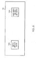
- FIG. 6 is a block diagram of an embodiment of a limits module included in the prognostics module of FIG. 2 ;
- FIG. 7 is a block diagram of one embodiment of a system including an unmanned aerial vehicle comprising the propulsion prognostics apparatus of FIG. 1 .
- Various embodiments of the invention provide propulsion prognostics apparatus for an unmanned aerial vehicle (UAV). Also provided are UAVs comprising the propulsion prognostics apparatus.
- UAV unmanned aerial vehicle
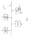
- FIG. 1 is a block diagram of one embodiment of a propulsion prognostics apparatus 100 for a UAV.
- propulsion prognostics apparatus 100 comprises a prognostics module 110, a power output sensor 120, memory 130, and a processor 140 coupled to one another via a bus 150 (e.g., a wired and/or wireless bus).
- bus 150 e.g., a wired and/or wireless bus.
- Prognostics module 110 is configured to monitor the pre-flight and/or in-flight health of a UAV.
- prognostics module 110 comprises a pre-flight module 112, an in-flight module 114, and a limits module 116.
- Various other embodiments of prognostics module 110 comprise pre-flight module 112, in-flight module 114, or limits module 116.
- prognostics module 110 comprises pre-flight module 112 and in-flight module 114, pre-flight module 112 and limits module 116, or in-flight module 114 and limits module 116.
- pre-flight module 112 comprises a tachometer 1122, a throttle position sensor 1124, and a barometric pressure sensor 1126.
- Tachometer 1122 is configured to be coupled to the engine of a UAV and is configured to sense the rotational speed (i.e., revolutions-per-minute (RPM)) of the engine prior to flight.
- Throttle position sensor 1124 is configured to be coupled to the throttle of the UAV and is further configured to sense the position of the throttle or, in other words, how much throttle the user is applying to the engine prior to flight.
- Barometric pressure sensor 1126 may be any system and/or device capable of sensing the barometric pressure in the environment surrounding pre-flight module 112 and/or the UAV.
- In-flight module 114 comprises a tachometer 1142, a throttle position sensor 1144, a barometric pressure sensor 1146, and a vertical rate of climb (VROC) sensor 1148.
- Tachometer 1142 is configured to be coupled to the engine of a UAV and is configured to sense the rotational speed (i.e., revolutions-per-minute (RPMs)) of the engine during flight.
- Throttle position sensor 1144 is configured to be coupled to the throttle of the UAV and is further configured to sense the position of the throttle or, in other words, how much throttle the user is applying to the engine during flight.
- Barometric pressure sensor 1146 may be any system and/or device capable of sensing the barometric pressure in the environment surrounding in-flight module 114 and/or the UAV.
- VROC sensor 1148 may be any system and/or device capable to sensing the vertical rate at which the UAV is climbing (or descending).
- pre-flight module 112 and in-flight module 114 share at least one common sensor.
- pre-flight module 112 and in-flight module 114 both comprise tachometer 1122 (or tachometer 1142), throttle position sensor 1124 (or throttle position sensor 1144), and/or barometric pressure sensor 1126 (or barometric pressure sensor 1146).
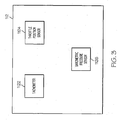
- In-flight module 114 further comprises VROC sensor 1148 as discussed above with reference to FIG. 4 .
- Limits module 116 comprises a throttle servo limit counter 1162 and a flight control vane servo limit counter 1164.
- Throttle servo limit counter 1162 is configured to be coupled to the throttle of a UAV and is further configured to count the number of times the user (or flight controller) attempts to apply the maximum amount of throttle. In common terms, throttle servo limit counter 1162 keeps track of the number of times that the user (or flight controller) attempts to "put the pedal to the metal.”
- Flight control vane servo limit counter 1164 is configured to be coupled to the flight control vanes (e.g., the front flight control vane, the back flight control vane, the left flight control vane, and the right flight control vane) on the UAV. Flight control vane servo limit counter 1164 is further configured to count the number of times the user (or flight controller) attempts to apply the maximum amount of deflection on each flight control vane. That is, flight control vane servo limit counter 1164 is configured to count the number of times the user (or flight controller) attempts to apply the maximum amount of roll to the front and back flight control vanes and to apply the maximum amount of pitch to the left and right flight control vanes.
- flight control vane servo limit counter 1164 is configured to be coupled to the flight control vanes (e.g., the front flight control vane, the back flight control vane, the left flight control vane, and the right flight control vane) on the UAV. Flight control vane servo limit counter 1164 is further configured to count the number of times
- power output sensor 120 is configured to be coupled to the engine of the UAV. Power output sensor 120 is further configured to sense the amount of power being output by the engine during pre-flight operations and/or during in-flight operations.
- Memory 130 may be any system, device, hardware, software, and combinations thereof capable of storing data.
- memory 130 is configured to store one or more look-up tables 135.
- look-up table 135 is a table including data related to the ideal or expected amount of power the engine of the UAV should be producing for a given set of inputs during pre-flight and/or in-flight operations.
- the data included in look-up table 135 relates to the ideal or expected amount of power the engine should be producing based on a rotational speed (in RPM) input for the engine, a throttle position input, and a barometric pressure input.
- the data included in look-up table 135 relates to the ideal or expected amount of power the engine should be producing based on a rotational speed input for the engine, a throttle position input, a barometric pressure input, and a vertical rate of climb input.
- Look-up table 135, in another embodiment, further comprises data related to the number of times the user (or flight controller) attempts to apply the maximum amount of throttle and/or attempts to apply the maximum amount of deflection to one or more flight control vanes in relation to the in-flight operation inputs. That is, when the actual power output of the engine during flight is questionable as to the ability of the engine to keep the UAV aloft, the number of times the user (or flight controller) attempts to apply the maximum amount of throttle and/or the maximum amount of deflection for one or more flight control vanes may be further indicative of the airworthiness of the UAV.
- Processor 140 may be any system, device, hardware, software, and combinations thereof capable of determining the airworthiness of a UAV during pre-flight operations and/or during in-flight operations.
- processor 140 is configured to receive sensor data (e.g., rotational speed data, throttle position data, and/or barometric pressure data) from prognostics module 110 and use look-up table 135 to determine the amount of power the engine of the UAV should be producing (i.e., the ideal power or expected power) for pre-flight operations based on the conditions sensed by tachometer 1122 (or tachometer 1142), throttle position sensor 1124 (or throttle position sensor 1144), and/or barometric pressure sensor 1126 (or barometric pressure sensor 1146).
- Processor 140 is further configured to receive the actual amount of power the engine is producing from power output sensor 120 and compare the actual amount of power to the expected amount of power for pre-flight operations.
- Processor 140 is also configured to determine a "no go" or "go" status based on the comparison of the actual power to the pre-flight expected power. That is, if the actual power is less than a pre-determined threshold of the pre-flight expected power, the UAV is deemed unworthy for flight. Alternatively, if the actual power is greater than the pre-determined threshold of the flight-flight expected power, the UAV is deemed worthy for flight.
- processor 140 is configured to receive sensor data (e.g., rotational speed data, throttle position data, barometric pressure data, and/or VROC data) from prognostics module 110 and use look-up table 135 to determine the amount of power the engine of the UAV should be producing (i.e., the ideal power or expected power) for in-flight operations based on the conditions sensed by tachometer 1142 (or tachometer 1122), throttle position sensor 1144 (or throttle position sensor 1124), barometric pressure sensor 1146 (or barometric pressure sensor 1126), and VROC sensor 1148. Processor 140 is further configured to receive the actual amount of power the engine is producing from power output sensor 120 and compare the actual amount of power to the expected amount of power for in-flight operations.
- sensor data e.g., rotational speed data, throttle position data, barometric pressure data, and/or VROC data
- Processor 140 is also configured to determine a "land" or “continue” status based on the comparison of the actual power to the in-flight expected power. That is, if the actual power is less than a pre-determined threshold of the expected power for flight, the UAV is deemed unworthy to continue flying. Alternatively, if the actual power is greater than the pre-determined threshold of the expected power for flight, the UAV is deemed worthy to continue flying.
- processor 140 is configured to determine the airworthiness of the UAV during in-flight operations when the actual power is close to the pre-determined threshold of the expected power for flight. Specifically, processor 140 is configured to receive sensor data (e.g., counter data from throttle servo limit counter 1162 and/or flight control vane servo limit counter 1164) and use look-up table 135 to determine if the user (or flight controller) has exceeded a pre-determined threshold number of times of attempting to apply the maximum amount of throttle and/or maximum amount of deflection for one or more flight control vanes for the given conditions sensed by in-flight module 114.
- sensor data e.g., counter data from throttle servo limit counter 1162 and/or flight control vane servo limit counter 116
- look-up table 135 to determine if the user (or flight controller) has exceeded a pre-determined threshold number of times of attempting to apply the maximum amount of throttle and/or maximum amount of deflection for one or more flight control vanes for the given conditions sensed by in
- the UAV if the number of maximum throttle and/or maximum deflection counts is greater than a pre-determined threshold number of counts for a particular set of in-flight conditions, the UAV is deemed unworthy to continue flying. Alternatively, if the number of maximum throttle and/or maximum deflection counts is less than the pre-determined threshold number of counts for the particular set of in-flight conditions, the UAV is deemed worthy to continue flying.
- FIG. 7 is a block diagram of one embodiment of a system 700 comprising a UAV 750 including propulsion prognostics apparatus 100.
- UAV 750 may be any UAV known in the art or developed in the future. As such, UAV 750 comprises an engine system, a throttle, and directional flight control vanes, each of which is not specifically shown in FIG. 7 , but is inferred.
- UAV 750 is a ducted fan UAV manufactured by Honeywell International, Inc., although UAVs manufactured by other entities are also contemplated by this embodiment.
- UAV 750 is a ducted fan vertical take-off and landing (VTOL) UAV manufactured by Honeywell International, Inc., although VTOL UAVs manufactured by other entities are also contemplated by this embodiment.
- VTOL ducted fan vertical take-off and landing
Landscapes
- Engineering & Computer Science (AREA)
- Physics & Mathematics (AREA)
- General Physics & Mathematics (AREA)
- Automation & Control Theory (AREA)
- Theoretical Computer Science (AREA)
- Evolutionary Computation (AREA)
- Computing Systems (AREA)
- General Engineering & Computer Science (AREA)
- Data Mining & Analysis (AREA)
- Mathematical Physics (AREA)
- Software Systems (AREA)
- Computational Linguistics (AREA)
- Artificial Intelligence (AREA)
- Chemical & Material Sciences (AREA)
- Combustion & Propulsion (AREA)
- Combined Controls Of Internal Combustion Engines (AREA)
- Control Of Position, Course, Altitude, Or Attitude Of Moving Bodies (AREA)
Claims (8)
- Antriebsprognosevorrichtung (100) für einen unbemannten Flugkörper (UAV) (750) mit einem Triebwerksystem, welches ein Mantelstrom-Fan-Antriebssystem aufweist, das Flugsteuerruder verwendet, aufweisend:ein Prognosemodul (110), das dafür ausgelegt ist, Prognosedaten zu erzeugen, wobei das Prognosemodul eine Nachschlagtabelle (135) aufweist, die Prognosedaten, welche mehrere erwartete Leistungsabgaben beinhalten, eine Schwellenanzahl der Vollgas-Versuche und eine Schwellenanzahl der maximalen Flugsteuerruder-Ausschläge speichert;einen Leistungsabgabesensor (120), der dafür ausgelegt ist, mit dem Triebwerksystem gekoppelt zu werden, und dafür ausgelegt ist, Leistungsabgabedaten zu erzeugen, die eine tatsächliche Leistungsabgabe des Triebwerksystems repräsentieren; undeinen Prozessor (140), der mit dem Prognosemodul und dem Leistungsabgabesensor gekoppelt ist, wobei der Prozessor dafür ausgelegt ist:die Prognosedaten und die Leistungsabgabedaten zu empfangen,die Prognosedaten und die Leistungsabgabedaten zu vergleichen, undauf der Basis des Vergleichs eine Fähigkeit des UAV zur Flugfortsetzung zu beurteilen.
- Antriebsprognosevorrichtung nach Anspruch 1, wobei das Prognosemodul ferner aufweist:einen Tachometer (1122), der dafür ausgelegt ist, mit dem Triebwerksystem gekoppelt zu werden;einen Drosselklappenpositionssensor (1124), der dafür ausgelegt ist, mit dem Triebwerksystem gekoppelt zu werden;einen barometrischen Drucksensor (1126); undeinen Speicher (130), der mit dem Prozessor gekoppelt ist, wobei der Speicher eine Nachschlagtabelle (135) aufweist, welche die mehreren erwarteten Leistungsabgaben für das Triebwerksystem speichert, wobei jede erwartete Leistungsabgabe einen Betrag der Leistung repräsentiert, welche das Triebwerksystem für einen bestimmten Satz aus einer gegebenen Drehzahl des Triebwerksystems, einem gegebenen Drosselbefehl und einer gegebenen barometrischen Druckbedingung erzeugen sollte.
- Antriebsprognosevorrichtung nach Anspruch 2, wobei der Prozessor ferner dafür ausgelegt ist:auf der Basis einer von dem Tachometer erfassten Drehzahl des Triebwerksystems, einer von dem Drosselklappenpositionssensor erfassten Drosselklappenposition und eines von dem barometrischen Drucksensor erfassten barometrischen Drucks eine erwartete Leistungsabgabe von den mehreren erwarteten Leistungsabgaben zu bestimmen; undbeim Bestimmen der Lufttüchtigkeit des UAV die erwartete Leistungsabgabe mit der tatsächlichen Leistungsabgabe zu vergleichen.
- Antriebsprognosevorrichtung nach Anspruch 1, wobei das Prognosemodul aufweist:einen Tachometer (1142), der dafür ausgelegt ist, mit dem Triebwerksystem gekoppelt zu werden;einen Drosselklappenpositionssensor (1144), der dafür ausgelegt ist, mit dem Triebwerksystem gekoppelt zu werden;einen barometrischen Drucksensor (1146);einen Sensor für die vertikale Steigrate (1148); undeinen Speicher (130), der mit dem Prozessor gekoppelt ist, wobei der Speicher eine Nachschlagtabelle (135) aufweist, welche mehrere erwartete Leistungsabgaben für das Triebwerksystem speichert, wobei jede erwartete Leistungsabgabe einen Betrag der Leistung repräsentiert, welche das Triebwerksystem für einen bestimmten Satz aus einer gegebenen Drehzahl des Triebwerksystems, einem gegebenen Drosselbefehl, einer gegebenen barometrischen Druckbedingung und einer gegebenen vertikalen Steigrate erzeugen sollte.
- Antriebsprognosevorrichtung nach Anspruch 4, wobei der Prozessor ferner dafür ausgelegt ist:auf der Basis einer von dem Tachometer erfassten Drehzahl des Triebwerksystems, einer von dem Drosselklappenpositionssensor erfassten Drosselklappenposition, eines von dem barometrischen Drucksensor erfassten barometrischen Drucks und einer von dem Sensor für die vertikale Steigrate erfassten vertikalen Steigrate eine erwartete Leistungsabgabe von den mehreren erwarteten Leistungsabgaben zu bestimmen; undbeim Bestimmen der Lufttüchtigkeit des UAV die erwartete Leistungsabgabe mit der tatsächlichen Leistungsabgabe zu vergleichen.
- Antriebsprognosevorrichtung nach Anspruch 1, wobei das Prognosemodul aufweist:ein In-Flight-Modul (112), welches aufweist:einen Tachometer (1122/1142), der dafür ausgelegt ist, mit dem Triebwerksystem gekoppelt zu werden,einen Drosselklappenpositionssensor (1124/1144), der dafür ausgelegt ist, mit dem Triebwerksystem gekoppelt zu werden, undeinen barometrischen Drucksensor (1126/1146).
- Antriebsprognosevorrichtung nach Anspruch 6, welche ferner einen mit dem Prozessor gekoppelten Speicher (130) aufweist, wobei der Speicher aufweist:eine Nachschlagtabelle (135), welche mehrere erwartete Leistungsabgaben für das Triebwerksystem speichert, wobei jede erwartete Leistungsabgabe einen Betrag der In-Flight-Leistung repräsentiert, welche das Triebwerksystem für einen bestimmten Satz aus einer gegebenen Drehzahl des Triebwerksystems, einem gegebenen Drosselbefehl, einer gegebenen barometrischen Druckbedingung und einer gegebenen vertikalen Steigrate erzeugen sollte.
- Antriebsprognosevorrichtung nach Anspruch 7, wobei der Prozessor ferner dafür ausgelegt ist:auf der Basis einer von dem Tachometer erfassten ersten Drehzahl des Triebwerksystems, einer von dem Drosselklappenpositionssensor erfassten ersten Drosselklappenposition und eines von dem barometrischen Drucksensor erfassten ersten barometrischen Drucks eine erste erwartete Leistungsabgabe von den mehreren erwarteten Leistungsabgaben zu bestimmen;beim Bestimmen der Lufttüchtigkeit des UAV vor dem Flug die erste erwartete Leistungsabgabe mit einer ersten tatsächlichen Leistungsabgabe zu vergleichen;auf der Basis einer von dem Tachometer erfassten zweiten Drehzahl des Triebwerksystems, einer von dem Drosselklappenpositionssensor erfassten zweiten Drosselklappenposition, eines von dem barometrischen Drucksensor erfassten zweiten barometrischen Drucks und einer von dem Sensor für die vertikale Steigrate erfassten vertikalen Steigrate eine zweite erwartete Leistungsabgabe von den mehreren erwarteten Leistungsabgaben zu bestimmen; undbeim Bestimmen der Lufttüchtigkeit des UAV während des Fluges die zweite erwartete Leistungsabgabe mit einer zweiten tatsächlichen Leistungsabgabe zu vergleichen.
Applications Claiming Priority (1)
| Application Number | Priority Date | Filing Date | Title |
|---|---|---|---|
| US12/268,696 US9304512B2 (en) | 2008-11-11 | 2008-11-11 | Propulsion prognostics apparatus and systems for unmanned aerial vehicles |
Publications (3)
| Publication Number | Publication Date |
|---|---|
| EP2184703A2 EP2184703A2 (de) | 2010-05-12 |
| EP2184703A3 EP2184703A3 (de) | 2012-02-08 |
| EP2184703B1 true EP2184703B1 (de) | 2015-10-14 |
Family
ID=41728317
Family Applications (1)
| Application Number | Title | Priority Date | Filing Date |
|---|---|---|---|
| EP09169099.0A Active EP2184703B1 (de) | 2008-11-11 | 2009-08-31 | Antriebsprognosevorrichtung und Systeme für unbemannte Flugkörper |
Country Status (2)
| Country | Link |
|---|---|
| US (1) | US9304512B2 (de) |
| EP (1) | EP2184703B1 (de) |
Families Citing this family (7)
| Publication number | Priority date | Publication date | Assignee | Title |
|---|---|---|---|---|
| US9435267B2 (en) | 2013-03-15 | 2016-09-06 | Rolls-Royce North American Technologies, Inc. | Integrated health management approach to propulsion control system protection limiting |
| US9828107B1 (en) * | 2014-08-25 | 2017-11-28 | Stc.Unm | Redundant component and intelligent computerized control system for multi-rotor VTOL aircraft |
| CN105334865A (zh) * | 2015-11-24 | 2016-02-17 | 余江 | 基于电量监控的飞行控制方法及飞行控制装置 |
| CN109302428A (zh) * | 2016-12-27 | 2019-02-01 | 深圳市大疆创新科技有限公司 | 无人机的控制方法和设备 |
| CN109269807A (zh) * | 2018-09-07 | 2019-01-25 | 桂林航天工业学院 | 无人机发动机磨合系统 |
| WO2021217355A1 (zh) * | 2020-04-27 | 2021-11-04 | 深圳市大疆创新科技有限公司 | 无人机的控制方法、系统和无人机 |
| US11866162B2 (en) * | 2020-12-01 | 2024-01-09 | Textron Innovations Inc. | Power management systems for electrically distributed yaw control systems |
Family Cites Families (35)
| Publication number | Priority date | Publication date | Assignee | Title |
|---|---|---|---|---|
| US5408412A (en) * | 1992-04-09 | 1995-04-18 | United Technologies Corporation | Engine fault diagnostic system |
| US6085127A (en) * | 1997-03-18 | 2000-07-04 | Aurora Flight Sciences Corporation | Fault tolerant automatic control system utilizing analytic redundancy |
| US5938401A (en) * | 1998-02-03 | 1999-08-17 | United Technologies Corporation | Automatic engine hydro-mechanical control unit preflight test |
| US6216066B1 (en) * | 1998-07-01 | 2001-04-10 | General Electric Company | System and method for generating alerts through multi-variate data assessment |
| US6606546B2 (en) * | 1999-12-01 | 2003-08-12 | Sinex Holdings, Llc | Aircraft maintenance program manager |
| US6684349B2 (en) * | 2000-01-18 | 2004-01-27 | Honeywell International Inc. | Reliability assessment and prediction system and method for implementing the same |
| SG97893A1 (en) * | 2000-06-29 | 2003-08-20 | Singapore Tech Aerospace Ltd | A method of monitoring and displaying health performance of an aircraft engine |
| US6664945B1 (en) * | 2000-09-19 | 2003-12-16 | Honeywell International Inc. | System and method for controlling communication and navigational devices |
| US7362551B2 (en) * | 2001-02-01 | 2008-04-22 | Hydro-Aire, Inc. | Aircraft applicable circuit imbalance detection and circuit interrupter and packaging thereof |
| US6567729B2 (en) * | 2001-03-28 | 2003-05-20 | Pt Holdings Ltd. | System and method of analyzing aircraft removal data for preventative maintenance |
| US6907416B2 (en) * | 2001-06-04 | 2005-06-14 | Honeywell International Inc. | Adaptive knowledge management system for vehicle trend monitoring, health management and preventive maintenance |
| US6526356B1 (en) * | 2001-06-19 | 2003-02-25 | The Aerospace Corporation | Rocket engine gear defect monitoring method |
| US6622972B2 (en) * | 2001-10-31 | 2003-09-23 | The Boeing Company | Method and system for in-flight fault monitoring of flight control actuators |
| JP4343691B2 (ja) * | 2001-11-13 | 2009-10-14 | グッドリッチ・ポンプ・アンド・エンジン・コントロール・システムズ・インコーポレーテッド | ガスタービン・エンジン用故障管理システム |
| US6748341B2 (en) * | 2002-04-12 | 2004-06-08 | George E. Crowder, Jr. | Method and device for machinery diagnostics and prognostics |
| US7308614B2 (en) * | 2002-04-30 | 2007-12-11 | Honeywell International Inc. | Control sequencing and prognostics health monitoring for digital power conversion and load management |
| US6751536B1 (en) * | 2002-12-04 | 2004-06-15 | The Boeing Company | Diagnostic system and method for enabling multistage decision optimization for aircraft preflight dispatch |
| US7027953B2 (en) * | 2002-12-30 | 2006-04-11 | Rsl Electronics Ltd. | Method and system for diagnostics and prognostics of a mechanical system |
| US6817171B2 (en) * | 2003-01-17 | 2004-11-16 | Daimlerchrysler Corporation | System and method for predicting concentration of undesirable exhaust emissions from an engine |
| US7212942B2 (en) * | 2003-06-10 | 2007-05-01 | Precision Innovations Llc | Power available and limitation indicator for use with an aircraft engine |
| US7343232B2 (en) * | 2003-06-20 | 2008-03-11 | Geneva Aerospace | Vehicle control system including related methods and components |
| US7689383B2 (en) * | 2003-11-20 | 2010-03-30 | The Boeing Company | Component health assessment for reconfigurable control |
| US7031812B1 (en) * | 2004-03-15 | 2006-04-18 | Howell Instruments, Inc. | System and method for monitoring aircraft engine health and determining engine power available, and applications thereof |
| US7552005B2 (en) * | 2004-03-16 | 2009-06-23 | Honeywell International Inc. | Method for fault diagnosis of a turbine engine |
| US7081729B2 (en) * | 2004-03-23 | 2006-07-25 | The Boeing Company | Variable-structure diagnostics approach achieving optimized low-frequency data sampling for EMA motoring subsystem |
| US7769507B2 (en) * | 2004-08-26 | 2010-08-03 | United Technologies Corporation | System for gas turbine health monitoring data fusion |
| US7103507B2 (en) * | 2004-09-28 | 2006-09-05 | Dimitry Gorinevsky | Structure health monitoring system and method |
| US7656637B2 (en) * | 2004-10-12 | 2010-02-02 | The Boeing Company | Power control system pseudo power-up, aircraft including the power control system and method of controlling power in an aircraft |
| US7379799B2 (en) * | 2005-06-29 | 2008-05-27 | General Electric Company | Method and system for hierarchical fault classification and diagnosis in large systems |
| US7370516B2 (en) * | 2005-11-21 | 2008-05-13 | General Motors Corporation | Method for estimating transmission input torque |
| US20070142980A1 (en) * | 2005-12-19 | 2007-06-21 | Marc Ausman | Avionics method and apparatus |
| US8157205B2 (en) * | 2006-03-04 | 2012-04-17 | Mcwhirk Bruce Kimberly | Multibody aircrane |
| FR2910986A1 (fr) * | 2007-01-03 | 2008-07-04 | Airbus France Sas | Methode de prediction de la fiabilite operationnelle d'un systeme avionique. |
| US8131406B2 (en) * | 2008-04-09 | 2012-03-06 | Lycoming Engines, A Division Of Avco Corporation | Piston engine aircraft automated pre-flight testing |
| US8954228B2 (en) * | 2008-12-30 | 2015-02-10 | Rolls-Royce Corporation | Gas turbine engine failure detection |
-
2008
- 2008-11-11 US US12/268,696 patent/US9304512B2/en active Active
-
2009
- 2009-08-31 EP EP09169099.0A patent/EP2184703B1/de active Active
Also Published As
| Publication number | Publication date |
|---|---|
| EP2184703A2 (de) | 2010-05-12 |
| US20100286860A1 (en) | 2010-11-11 |
| EP2184703A3 (de) | 2012-02-08 |
| US9304512B2 (en) | 2016-04-05 |
Similar Documents
| Publication | Publication Date | Title |
|---|---|---|
| US9304512B2 (en) | Propulsion prognostics apparatus and systems for unmanned aerial vehicles | |
| US11433997B2 (en) | Rotorcraft anti-torque systems and methods therefor | |
| Fleming et al. | Improving control system effectiveness for ducted fan VTOL UAVs operating in crosswinds | |
| CN103895862B (zh) | 通过预测旋翼的两个旋转速度设定点之间的扭矩需求驱动旋翼飞行器旋翼的旋转的方法 | |
| US10435147B2 (en) | Multirotor aircraft control systems | |
| EP4082906B1 (de) | Flugzeug mit einem mehrpropeller-antriebssystem zur steuerung von flugorientierungsübergängen | |
| JP2021059159A (ja) | 電動化航空機及びその空力性能制御方法 | |
| Erturk et al. | Dynamic simulation and control of mass-actuated airplane | |
| Wang et al. | Design, implementation and verification of a quadrotor tail-sitter VTOL UAV | |
| Chang et al. | Flight testing full conversion of a 40-kg-class tilt-duct unmanned aerial vehicle | |
| Choi et al. | Static analysis of a small scale ducted-fan UAV using wind tunnel data | |
| Ohanian III et al. | Nondimensional modeling of ducted-fan aerodynamics | |
| CN121742498A (zh) | 用于飞行器控制的自调整系统 | |
| Kratz et al. | Enhancement of a conceptual hybrid electric tilt-wing propulsion system through application of the turbine electrified energy management concept | |
| Gowtham et al. | Modelling and numerical analysis of attitude control flaps of a UAV | |
| Ohanian et al. | A compact method for modeling the aerodynamics of ducted fan vehicles | |
| Altamirano et al. | Investigation of Longitudinal Aero-Propulsive Interactions of a Small Quadrotor Unmanned Aircraft System | |
| JPH0323399B2 (de) | ||
| EP2947008A2 (de) | Adaptive Flugsteuerung | |
| Mogili et al. | Study of takeoff constraints for lifting an agriculture pesticide sprinkling multi-rotor system | |
| Dantsker et al. | Propulsion system design, optimization, simulation, and testing for a long-endurance solar-powered unmanned aircraft | |
| CN121666346A (zh) | 用于航空器的飞行控制中的振动衰减的系统和方法 | |
| Miller et al. | Development and testing of a coaxial helicopter controlled by shifting the center of gravity | |
| Bradley | Potential Crash Location (PCL) Model | |
| Podsędkowski et al. | Enhancing drone propellers: practical insights from BEM-based pitch optimization |
Legal Events
| Date | Code | Title | Description |
|---|---|---|---|
| PUAI | Public reference made under article 153(3) epc to a published international application that has entered the european phase |
Free format text: ORIGINAL CODE: 0009012 |
|
| 17P | Request for examination filed |
Effective date: 20090831 |
|
| AK | Designated contracting states |
Kind code of ref document: A2 Designated state(s): AT BE BG CH CY CZ DE DK EE ES FI FR GB GR HR HU IE IS IT LI LT LU LV MC MK MT NL NO PL PT RO SE SI SK SM TR |
|
| AX | Request for extension of the european patent |
Extension state: AL BA RS |
|
| REG | Reference to a national code |
Ref country code: DE Ref legal event code: R079 Ref document number: 602009034184 Country of ref document: DE Free format text: PREVIOUS MAIN CLASS: G06N0007000000 Ipc: G06N0005000000 |
|
| PUAL | Search report despatched |
Free format text: ORIGINAL CODE: 0009013 |
|
| AK | Designated contracting states |
Kind code of ref document: A3 Designated state(s): AT BE BG CH CY CZ DE DK EE ES FI FR GB GR HR HU IE IS IT LI LT LU LV MC MK MT NL NO PL PT RO SE SI SK SM TR |
|
| AX | Request for extension of the european patent |
Extension state: AL BA RS |
|
| RIC1 | Information provided on ipc code assigned before grant |
Ipc: G06N 5/00 20060101AFI20120105BHEP |
|
| 17Q | First examination report despatched |
Effective date: 20120711 |
|
| GRAP | Despatch of communication of intention to grant a patent |
Free format text: ORIGINAL CODE: EPIDOSNIGR1 |
|
| INTG | Intention to grant announced |
Effective date: 20150603 |
|
| GRAS | Grant fee paid |
Free format text: ORIGINAL CODE: EPIDOSNIGR3 |
|
| GRAA | (expected) grant |
Free format text: ORIGINAL CODE: 0009210 |
|
| AK | Designated contracting states |
Kind code of ref document: B1 Designated state(s): AT BE BG CH CY CZ DE DK EE ES FI FR GB GR HR HU IE IS IT LI LT LU LV MC MK MT NL NO PL PT RO SE SI SK SM TR |
|
| REG | Reference to a national code |
Ref country code: GB Ref legal event code: FG4D |
|
| REG | Reference to a national code |
Ref country code: AT Ref legal event code: REF Ref document number: 755628 Country of ref document: AT Kind code of ref document: T Effective date: 20151015 Ref country code: CH Ref legal event code: EP |
|
| REG | Reference to a national code |
Ref country code: IE Ref legal event code: FG4D |
|
| REG | Reference to a national code |
Ref country code: DE Ref legal event code: R096 Ref document number: 602009034184 Country of ref document: DE |
|
| RAP2 | Party data changed (patent owner data changed or rights of a patent transferred) |
Owner name: HONEYWELL INTERNATIONAL INC. |
|
| REG | Reference to a national code |
Ref country code: NL Ref legal event code: MP Effective date: 20151014 |
|
| REG | Reference to a national code |
Ref country code: LT Ref legal event code: MG4D |
|
| REG | Reference to a national code |
Ref country code: AT Ref legal event code: MK05 Ref document number: 755628 Country of ref document: AT Kind code of ref document: T Effective date: 20151014 |
|
| PG25 | Lapsed in a contracting state [announced via postgrant information from national office to epo] |
Ref country code: LT Free format text: LAPSE BECAUSE OF FAILURE TO SUBMIT A TRANSLATION OF THE DESCRIPTION OR TO PAY THE FEE WITHIN THE PRESCRIBED TIME-LIMIT Effective date: 20151014 Ref country code: NO Free format text: LAPSE BECAUSE OF FAILURE TO SUBMIT A TRANSLATION OF THE DESCRIPTION OR TO PAY THE FEE WITHIN THE PRESCRIBED TIME-LIMIT Effective date: 20160114 Ref country code: IT Free format text: LAPSE BECAUSE OF FAILURE TO SUBMIT A TRANSLATION OF THE DESCRIPTION OR TO PAY THE FEE WITHIN THE PRESCRIBED TIME-LIMIT Effective date: 20151014 Ref country code: HR Free format text: LAPSE BECAUSE OF FAILURE TO SUBMIT A TRANSLATION OF THE DESCRIPTION OR TO PAY THE FEE WITHIN THE PRESCRIBED TIME-LIMIT Effective date: 20151014 Ref country code: IS Free format text: LAPSE BECAUSE OF FAILURE TO SUBMIT A TRANSLATION OF THE DESCRIPTION OR TO PAY THE FEE WITHIN THE PRESCRIBED TIME-LIMIT Effective date: 20160214 Ref country code: ES Free format text: LAPSE BECAUSE OF FAILURE TO SUBMIT A TRANSLATION OF THE DESCRIPTION OR TO PAY THE FEE WITHIN THE PRESCRIBED TIME-LIMIT Effective date: 20151014 Ref country code: NL Free format text: LAPSE BECAUSE OF FAILURE TO SUBMIT A TRANSLATION OF THE DESCRIPTION OR TO PAY THE FEE WITHIN THE PRESCRIBED TIME-LIMIT Effective date: 20151014 |
|
| PG25 | Lapsed in a contracting state [announced via postgrant information from national office to epo] |
Ref country code: AT Free format text: LAPSE BECAUSE OF FAILURE TO SUBMIT A TRANSLATION OF THE DESCRIPTION OR TO PAY THE FEE WITHIN THE PRESCRIBED TIME-LIMIT Effective date: 20151014 Ref country code: SE Free format text: LAPSE BECAUSE OF FAILURE TO SUBMIT A TRANSLATION OF THE DESCRIPTION OR TO PAY THE FEE WITHIN THE PRESCRIBED TIME-LIMIT Effective date: 20151014 Ref country code: PL Free format text: LAPSE BECAUSE OF FAILURE TO SUBMIT A TRANSLATION OF THE DESCRIPTION OR TO PAY THE FEE WITHIN THE PRESCRIBED TIME-LIMIT Effective date: 20151014 Ref country code: GR Free format text: LAPSE BECAUSE OF FAILURE TO SUBMIT A TRANSLATION OF THE DESCRIPTION OR TO PAY THE FEE WITHIN THE PRESCRIBED TIME-LIMIT Effective date: 20160115 Ref country code: PT Free format text: LAPSE BECAUSE OF FAILURE TO SUBMIT A TRANSLATION OF THE DESCRIPTION OR TO PAY THE FEE WITHIN THE PRESCRIBED TIME-LIMIT Effective date: 20160215 Ref country code: FI Free format text: LAPSE BECAUSE OF FAILURE TO SUBMIT A TRANSLATION OF THE DESCRIPTION OR TO PAY THE FEE WITHIN THE PRESCRIBED TIME-LIMIT Effective date: 20151014 Ref country code: LV Free format text: LAPSE BECAUSE OF FAILURE TO SUBMIT A TRANSLATION OF THE DESCRIPTION OR TO PAY THE FEE WITHIN THE PRESCRIBED TIME-LIMIT Effective date: 20151014 |
|
| REG | Reference to a national code |
Ref country code: DE Ref legal event code: R097 Ref document number: 602009034184 Country of ref document: DE |
|
| REG | Reference to a national code |
Ref country code: FR Ref legal event code: PLFP Year of fee payment: 8 |
|
| PG25 | Lapsed in a contracting state [announced via postgrant information from national office to epo] |
Ref country code: CZ Free format text: LAPSE BECAUSE OF FAILURE TO SUBMIT A TRANSLATION OF THE DESCRIPTION OR TO PAY THE FEE WITHIN THE PRESCRIBED TIME-LIMIT Effective date: 20151014 |
|
| PLBE | No opposition filed within time limit |
Free format text: ORIGINAL CODE: 0009261 |
|
| STAA | Information on the status of an ep patent application or granted ep patent |
Free format text: STATUS: NO OPPOSITION FILED WITHIN TIME LIMIT |
|
| PG25 | Lapsed in a contracting state [announced via postgrant information from national office to epo] |
Ref country code: EE Free format text: LAPSE BECAUSE OF FAILURE TO SUBMIT A TRANSLATION OF THE DESCRIPTION OR TO PAY THE FEE WITHIN THE PRESCRIBED TIME-LIMIT Effective date: 20151014 Ref country code: DK Free format text: LAPSE BECAUSE OF FAILURE TO SUBMIT A TRANSLATION OF THE DESCRIPTION OR TO PAY THE FEE WITHIN THE PRESCRIBED TIME-LIMIT Effective date: 20151014 Ref country code: SK Free format text: LAPSE BECAUSE OF FAILURE TO SUBMIT A TRANSLATION OF THE DESCRIPTION OR TO PAY THE FEE WITHIN THE PRESCRIBED TIME-LIMIT Effective date: 20151014 Ref country code: RO Free format text: LAPSE BECAUSE OF FAILURE TO SUBMIT A TRANSLATION OF THE DESCRIPTION OR TO PAY THE FEE WITHIN THE PRESCRIBED TIME-LIMIT Effective date: 20151014 Ref country code: SM Free format text: LAPSE BECAUSE OF FAILURE TO SUBMIT A TRANSLATION OF THE DESCRIPTION OR TO PAY THE FEE WITHIN THE PRESCRIBED TIME-LIMIT Effective date: 20151014 |
|
| 26N | No opposition filed |
Effective date: 20160715 |
|
| PG25 | Lapsed in a contracting state [announced via postgrant information from national office to epo] |
Ref country code: SI Free format text: LAPSE BECAUSE OF FAILURE TO SUBMIT A TRANSLATION OF THE DESCRIPTION OR TO PAY THE FEE WITHIN THE PRESCRIBED TIME-LIMIT Effective date: 20151014 |
|
| PG25 | Lapsed in a contracting state [announced via postgrant information from national office to epo] |
Ref country code: BE Free format text: LAPSE BECAUSE OF FAILURE TO SUBMIT A TRANSLATION OF THE DESCRIPTION OR TO PAY THE FEE WITHIN THE PRESCRIBED TIME-LIMIT Effective date: 20151014 |
|
| PG25 | Lapsed in a contracting state [announced via postgrant information from national office to epo] |
Ref country code: MC Free format text: LAPSE BECAUSE OF FAILURE TO SUBMIT A TRANSLATION OF THE DESCRIPTION OR TO PAY THE FEE WITHIN THE PRESCRIBED TIME-LIMIT Effective date: 20151014 |
|
| REG | Reference to a national code |
Ref country code: CH Ref legal event code: PL |
|
| PG25 | Lapsed in a contracting state [announced via postgrant information from national office to epo] |
Ref country code: CH Free format text: LAPSE BECAUSE OF NON-PAYMENT OF DUE FEES Effective date: 20160831 Ref country code: LI Free format text: LAPSE BECAUSE OF NON-PAYMENT OF DUE FEES Effective date: 20160831 |
|
| REG | Reference to a national code |
Ref country code: IE Ref legal event code: MM4A |
|
| PG25 | Lapsed in a contracting state [announced via postgrant information from national office to epo] |
Ref country code: IE Free format text: LAPSE BECAUSE OF NON-PAYMENT OF DUE FEES Effective date: 20160831 |
|
| REG | Reference to a national code |
Ref country code: FR Ref legal event code: PLFP Year of fee payment: 9 |
|
| PG25 | Lapsed in a contracting state [announced via postgrant information from national office to epo] |
Ref country code: LU Free format text: LAPSE BECAUSE OF NON-PAYMENT OF DUE FEES Effective date: 20160831 |
|
| PG25 | Lapsed in a contracting state [announced via postgrant information from national office to epo] |
Ref country code: CY Free format text: LAPSE BECAUSE OF FAILURE TO SUBMIT A TRANSLATION OF THE DESCRIPTION OR TO PAY THE FEE WITHIN THE PRESCRIBED TIME-LIMIT Effective date: 20151014 Ref country code: HU Free format text: LAPSE BECAUSE OF FAILURE TO SUBMIT A TRANSLATION OF THE DESCRIPTION OR TO PAY THE FEE WITHIN THE PRESCRIBED TIME-LIMIT; INVALID AB INITIO Effective date: 20090831 |
|
| PG25 | Lapsed in a contracting state [announced via postgrant information from national office to epo] |
Ref country code: MK Free format text: LAPSE BECAUSE OF FAILURE TO SUBMIT A TRANSLATION OF THE DESCRIPTION OR TO PAY THE FEE WITHIN THE PRESCRIBED TIME-LIMIT Effective date: 20151014 Ref country code: TR Free format text: LAPSE BECAUSE OF FAILURE TO SUBMIT A TRANSLATION OF THE DESCRIPTION OR TO PAY THE FEE WITHIN THE PRESCRIBED TIME-LIMIT Effective date: 20151014 Ref country code: MT Free format text: LAPSE BECAUSE OF NON-PAYMENT OF DUE FEES Effective date: 20160831 |
|
| PG25 | Lapsed in a contracting state [announced via postgrant information from national office to epo] |
Ref country code: BG Free format text: LAPSE BECAUSE OF FAILURE TO SUBMIT A TRANSLATION OF THE DESCRIPTION OR TO PAY THE FEE WITHIN THE PRESCRIBED TIME-LIMIT Effective date: 20151014 |
|
| REG | Reference to a national code |
Ref country code: FR Ref legal event code: PLFP Year of fee payment: 10 |
|
| REG | Reference to a national code |
Ref country code: DE Ref legal event code: R081 Ref document number: 602009034184 Country of ref document: DE Owner name: KIA CORPORATION, KR Free format text: FORMER OWNER: HONEYWELL INTERNATIONAL INC., MORRISTOWN, N.J., US Ref country code: DE Ref legal event code: R081 Ref document number: 602009034184 Country of ref document: DE Owner name: HYUNDAI MOTOR COMPANY, KR Free format text: FORMER OWNER: HONEYWELL INTERNATIONAL INC., MORRISTOWN, N.J., US |
|
| REG | Reference to a national code |
Ref country code: GB Ref legal event code: 732E Free format text: REGISTERED BETWEEN 20221117 AND 20221123 |
|
| P01 | Opt-out of the competence of the unified patent court (upc) registered |
Effective date: 20230505 |
|
| PGFP | Annual fee paid to national office [announced via postgrant information from national office to epo] |
Ref country code: DE Payment date: 20250721 Year of fee payment: 17 |
|
| PGFP | Annual fee paid to national office [announced via postgrant information from national office to epo] |
Ref country code: GB Payment date: 20250722 Year of fee payment: 17 |
|
| PGFP | Annual fee paid to national office [announced via postgrant information from national office to epo] |
Ref country code: FR Payment date: 20250725 Year of fee payment: 17 |