EP2184672A1 - Information display apparatus, mobile information unit, display control method and display control program - Google Patents
Information display apparatus, mobile information unit, display control method and display control program Download PDFInfo
- Publication number
- EP2184672A1 EP2184672A1 EP09252461A EP09252461A EP2184672A1 EP 2184672 A1 EP2184672 A1 EP 2184672A1 EP 09252461 A EP09252461 A EP 09252461A EP 09252461 A EP09252461 A EP 09252461A EP 2184672 A1 EP2184672 A1 EP 2184672A1
- Authority
- EP
- European Patent Office
- Prior art keywords
- contact
- unit
- basis
- display
- direction indicated
- Prior art date
- Legal status (The legal status is an assumption and is not a legal conclusion. Google has not performed a legal analysis and makes no representation as to the accuracy of the status listed.)
- Granted
Links
Images




Classifications
-
- G—PHYSICS
- G06—COMPUTING OR CALCULATING; COUNTING
- G06F—ELECTRIC DIGITAL DATA PROCESSING
- G06F3/00—Input arrangements for transferring data to be processed into a form capable of being handled by the computer; Output arrangements for transferring data from processing unit to output unit, e.g. interface arrangements
- G06F3/01—Input arrangements or combined input and output arrangements for interaction between user and computer
- G06F3/048—Interaction techniques based on graphical user interfaces [GUI]
- G06F3/0487—Interaction techniques based on graphical user interfaces [GUI] using specific features provided by the input device, e.g. functions controlled by the rotation of a mouse with dual sensing arrangements, or of the nature of the input device, e.g. tap gestures based on pressure sensed by a digitiser
- G06F3/0488—Interaction techniques based on graphical user interfaces [GUI] using specific features provided by the input device, e.g. functions controlled by the rotation of a mouse with dual sensing arrangements, or of the nature of the input device, e.g. tap gestures based on pressure sensed by a digitiser using a touch-screen or digitiser, e.g. input of commands through traced gestures
Definitions
- the present invention relates to an information display apparatus, mobile information unit, display control method and program.
- a touch panel In recent years, various kinds of mobile devices such as a cellular phone unit, a portable music player and a PDA (personal digital assistant) that are equipped with a touch panel or a touch pad (both of them are referred to as a touch panel hereinafter) have been commercially produced.
- various types of touch panels such as those of a resistive film type, a pressure sensitive type, an electrostatic capacitor detecting type, an ultrasonic surface acoustic wave detecting type, an acoustic pulse recognition type, a vibration detecting type, an infrared light shielding type, an image recognition type and an electrostatic sensor type have been developed or commercially produced.
- the above-mentioned various types of touch panels are representative examples, and many other types have been also proposed. Because these types of touch panels may be produced using existing technologies, detailed explanation about these existing technologies is omitted.
- Japanese Patent Application Publication No. 2000-347787 See FIG. 1 thereof
- a touch panel display apparatus in which a pointer displayed on a display screen is controlled by the way the touch panel of the touch panel display apparatus is touched.
- the display of the pointer is controlled in such a way that the pointer is not displayed when the touched position of the touch panel belongs to the nondisplay area of the touch panel, and the pointer is displayed when the touched position of the touch panel belongs to the area other than the nondisplay area.
- a cellular phone unit in which a cursor displayed on a display screen is moved with the use of a pressure type pointing device that issues signals on the basis of a depressive force and a depressive direction.
- such a mobile device equipped with a touch panel as mentioned above displays several icons on its display screen, and the mobile device is configured to start an application program corresponding to an icon when a portion of panel corresponding to the display position of the icon is touched by a finger or the like.
- a user with large his fingers has to use a so-called stylus pen or the like to touch a desired icon in order to start a desired application.
- the user has to use another operation device (such as an arrow key) to start a desired application, and it is certain that these operations are very troublesome for the user.
- the present invention is proposed with the above mentioned actual situation in mind, and it provides an information display apparatus that makes the operation of its touch panel easy and enables a user to surely touch a desired icon and the like, a mobile information unit having the same function as the information display apparatus, a display control method and a display control program used therein.
- An information display apparatus includes a contact detecting panel unit that detects at least contact with the approximately transparent panel surface thereof made by an external object and a display panel unit installed on the panel back surface of the contact detecting panel unit.
- the information display apparatus includes an analyzing unit and a pointer control unit.
- the analyzing unit analyzes a contact position of the panel surface of the contact detecting panel unit with which the external object makes contact and a direction indicated by a specific portion of the external object on the basis of output values of the contact detecting panel unit.
- the pointer control unit also controls a display position and a pointing direction of a predefined pointer image displayed on the display panel unit on the basis of the contact position and the direction indicated by the specific portion, in which both the contact position and the direction indicated by the specific portion are obtained from the analyzing unit. Owing to the above configuration of the display control apparatus, the above-mentioned problems can be solved.
- the display control apparatus finds the contact position of the panel surface of the contact detecting panel unit with which the external object makes contact and the direction indicated by the specific portion of the external object, and determines the display position and pointing direction of the predefined pointer image displayed on the display panel unit on the basis of the contact position and the direction indicated by the specific portion.
- a user makes a choice of his/her desired icon or the like by using the pointer image instead of directly touching the icon using his/her finger etc.
- the pointer control unit controls the display position of the predefined pointer image in the direction indicated by the specific portion and in the vicinity of the contact position, and at the same time the pointer control unit controls the pointing direction of the predefined pointer image on the basis of the direction indicated by the specific portion.
- the pointer image is displayed not in the position specified by the user's finger etc. but it is displayed in the direction indicated by the specific portion of the user's finger etc. and in the vicinity of the contact position of the user's finger etc.
- the pointing direction of the pointer image becomes identical to the direction indicated by the specific portion of the user's finger.
- the contact position on the panel surface of the contact detecting panel unit with which the external object makes contact and the direction indicated by a specific portion of the external object are calculated and the display position and the pointing direction of the pointer image displayed on the display panel unit is determined on the basis of the above-mentioned contact position and direction, so that it may be possible that even a user with thick fingers operates the touch panel easily and surely touches a desired icon and the like.
- the information display apparatus is equipped with a touch panel that works as an input device for a user interface, that controls the display of a so-called mouse pointer on a display screen on the basis of input information from the touch panel.
- a touch panel that works as an input device for a user interface, that controls the display of a so-called mouse pointer on a display screen on the basis of input information from the touch panel.
- a cellular phone unit equipped with a touch panel of a pressure sensitive type that uses pressure sensors is taken as an example apparatus to which the present invention is applied. Therefore, the contents described hereinafter are only those regarding the preferred embodiment, and it goes without saying that the present invention is not limited to this specific embodiment.
- the present invention can be applied to various types of touch panels such as those of a resistive film type, an electrostatic capacitor detecting type, an ultrasonic surface acoustic wave detecting type, an acoustic pulse recognition type, a vibration detecting type, an infrared light shielding type, an image recognition type and an electrostatic sensor type.
- FIG. 1 is a block diagram showing an internal schematic configuration of a cellular phone unit according to this embodiment of the present invention.
- a communication antenna 12 and a communication circuit 11 are used for transmission and reception of signal waves of phone calls and packet communication; and frequency conversion, modulation, demodulation and the like of transmitter and receiver signals.
- a speaker 20 is composed of a phone call receiving speaker for the cellular phone unit and a speaker for alarm sounds, played-back music, etc.
- a microphone 21 is used for phone call transmission and collection of external sounds.
- a sound processing unit 22 performs various types of processes regarding phone call data, the sounds of played-back music, etc.
- An operating unit 13 is composed of various operating parts such as a numeric keypad, a call key, an end/power key, an arrow key, a shutter button, a jog dial, etc. that are all mounted on the chassis (not shown) of the cellular phone unit, and an operating signal generator that, when an operating part is operated, generates a signal corresponding to the operating part. Meanwhile, the functions of some keys, buttons, etc. of the operating unit 13 can be assigned to a touch panel unit 25, and then these keys, buttons, etc. can be omitted.
- a display unit 14 is a display device composed of, for example, a liquid crystal display panel or an organic EL display panel.
- a display control unit 15 controls a display driving circuit of the display unit 14 to display characters, symbols, icons, a mouse pointer, still images, moving images and the like on the display screen of the display unit 14.
- An image processing unit 23 performs various processes such as generating display image data for characters, symbols, still images, moving images and the like to be displayed on the display screen of the display unit 14. Meanwhile, the functions of the display control unit 15 can be performed by a control unit 10.
- a memory unit 16 stores, for example, an OS (operating system) program, various application programs such as a control program that the control unit 10 uses to control other units, a display control program for controlling the display of a mouse pointer etc. on the basis of the operation of a touch panel, and other various data.
- the display control of the mouse pointer etc. based on the operation of the touch panel according to an embodiment of the present invention will be described later.
- the memory unit 16 also stores necessary data and serves as a working area for the control unit 10.
- a program storing module 17 of the memory unit 16 stores various application programs relating to the embodiment of the present invention such as the display control program and a data storing module 18 stores various data including parameters and threshold values etc. used by the display control program.
- various programs, which are stored in the memory unit 16 and relate to the embodiment of the present invention including the display control program can be stored in the memory unit 16 via disk type storage media, external semiconductor memories, or via external storage media through cables or wireless networks using external interfaces.
- the touch panel unit 25 includes an approximately transparent panel that is disposed on the display panel surface of the display unit 14.
- the panel is a touch panel of a pressure sensitive type equipped with pressure sensors. Although the details will be described hereinafter, when an external object such as a user's finger applies pressure on the panel surface of the touch panel unit 25, the touch panel unit 25 detects the pressure and generates and outputs numerical values representing the applied pressure (pressure value signals).
- the panel surface of the touch panel unit 25 is divided into plural minute pressure detecting blocks, and each pressure detecting block has a pressure sensor. Output signals from these pressure sensors are sent to a touch panel control unit 24.
- the touch panel control unit 24 performs the start-up control (activation ON/OFF control) of the pressure sensors of the touch panel unit 25, and an analog-to-digital conversion in which the pressure value signals sent from activated pressure sensors are converted into pressure value data.
- the touch panel control unit 24 also performs position detecting processing in which the coordinate values on the panel for pressure-applied pressure sensors are generated. To put it concretely, the touch panel control unit 24 detects the positions on the touch panel at which the pressure-applied pressure sensors or pressure applied-pressure detecting blocks are disposed as coordinate values.
- the control unit 10 includes a CPU (central processing unit), and performs control of the units, various signal processing controls, etc. of the cellular phone unit according to this embodiment of the present invention.
- the control unit 10 executes the display control program stored in the program storing module 17 of the memory unit 16, and performs various accompanying data processing tasks. The details will be described hereinafter.
- the cellular phone unit according to this embodiment is equipped with various component parts that an ordinary cellular phone unit has.
- the pressure values detected from those pressure detecting blocks are different from each other because all the pressures caused by the contact portions of the finger or the like are not equal. In other words, when a finger or the like makes contact with the panel surface, there are various contact pressures from large ones to small ones.
- the pressure applied to the plane surface by the fingertip is the largest and the pressure applied by a portion of the finger gradually decreases as the portion gets closer to the base of the finger.
- the control unit 10 analyzes a pressure distribution caused by the finger as mentioned above using output signals from the touch panel control unit 24, and detects the direction indicated by the fingertip.
- FIG. 2 is an example of a schematic contact pressure distribution 40 when a finger 32 shown by dotted lines makes contact with a panel surface 30 of the touch panel unit 25.
- FIG. 3 shows an enlarged view of the pressure distribution 40 in FIG. 2 .
- intensities of the pressures are represented by pressure distribution lines 40a, 40b, 40c and 40d, which are like so-called contours regarding pressures.
- the area within the pressure distribution line 40a represents an area with the largest degree of pressure
- the area between the pressure distribution line 40a and 40b represents an area with the second largest degree of pressure
- the area between the pressure distribution line 40b and40c represents an area with the third largest degree of pressure
- the area between the pressure distribution line 40c and 40d represents an area with the smallest degree of pressure.
- the area outside the pressure distribution line 40d represents an area with the degree of pressure of nearly zero because the finger does not make contact with the area.
- the pressure distribution caused by the finger 32 shows that the pressure applied to the plane surface by the fingertip 32a is the largest and the pressure applied by a portion of the finger gradually decreases as the portion gets closer to the base of the finger 32b.
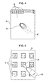
- FIG. 4 shows plural pressure detecting blocks 35 disposed on the touch panel 25 and an example of schematic contact pressure distribution 40 when the finger 32 makes contact with the panel surface 30.
- the sizes (areas) of pressure detecting blocks 35 are depicted as being larger than they actually are for illustration purposes, they are really far smaller than the sizes (areas) of pressure detecting blocks 35 depicted in FIG. 4 .
- the touch panel control unit 24 scans the pressure detecting blocks 35 disposed on the panel surface 30 sequentially as indicated by arrows in FIG. 4 , and when detecting a pressure detecting block 35 whose sensor outputs some pressure value, the touch panel control unit 24 performs more detailed pressure detection regarding pressure detecting blocks surrounding the pressure detecting block 35 whose sensor outputs the pressure value.
- control unit 10 calculates the pressure distribution 40 by analyzing the magnitudes of pressure values obtained from the pressure detecting blocks 35, and detects the direction indicated by the fingertip of the finger 32 on the basis of the pressure distribution 40.
- the cellular phone unit is configured to control the pointing direction indicated by a mouse pointer, for example, displayed on the display screen on the basis of the direction indicated by the fingertip of the finger 32 when the cellular phone unit detects the direction indicated by the fingertip on the basis of the pressure distribution caused by the finger 32 that makes contact with the above-mentioned panel surface 30.
- FIG. 5 and FIG. 6 the above-mentioned panel surface 30, image examples displayed on the display screen at the lower part of the panel surface 30, and the finger 32 that makes contact with the panel surface 30 are shown.
- the cellular phone unit detects the contact position of the finger 32 (the position on the panel surface 30 with which the finger 32 makes contact) when the finger 32 makes contact with the panel surface 30, and at the same time detects the direction indicated by the fingertip on the basis of the pressure distribution caused by the finger 32. Then, on the basis of the detected contact position and the detected direction indicated by the fingertip, the cellular phone unit controls the display position of the mouse pointer 33 and the direction indicated by the arrow of the mouse pointer.
- FIG. 5 shows the case where the finger 32 is placed on the right lower part of the panel surface 30 and the fingertip shows the direction from the lower part of the panel surface to the upper left.
- the control unit 10 performs display control so that the mouse pointer 33 is displayed in the position that is judged from the pressure distribution 40 to be both in the direction of the fingertip and in the vicinity of the fingertip and at the same time the arrow of the mouse pointer shows the direction from the lower right part of the panel surface to the upper left on the basis of the pressure distribution 40.
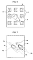
- FIG. 6 shows the case where the finger 32 is placed nearly on the middle part of the panel surface 30 and the fingertip shows the direction from the upper left part of the panel surface to the lower right.
- the control unit 10 performs display control so that the mouse pointer 33 is displayed in the position that is judged from the pressure distribution 40 to be both in the direction of the fingertip and in the vicinity of the fingertip and at the same time the arrow of the mouse pointer shows the direction from the upper left part of the panel surface to the lower right on the basis of the pressure distribution 40.
- the reason why the mouse pointer 33 is displayed in the position that is judged from the pressure distribution 40 to be both in the direction of the fingertip and in the vicinity of the fingertip is that attention is paid lest the mouse pointer 33 should be hidden by the finger 32 with consideration given to the fact that the fingertip is commonly used by the user to point at something.
- the cellular phone unit is configured to control the mouse pointer 33 so that the mouse pointer 33 moves along with the movement of the finger 32 when the finger 32 moves along the panel surface 30.
- FIG. 7 and FIG. 8 show the relation among the panel surface 30, the finger 32 that makes contact with the panel surface 30, and the mouse pointer 33 displayed on the display screen.
- the cellular phone unit detects the change of the contact position of the finger 32 and the change of the pressure distribution along with the movement of the finger 32 when the finger 32 moves while keeping contact with the panel surface 30. Then, on the basis of the detected change of the contact position and the detected change of the pressure distribution, the cellular phone unit controls the display position of the mouse pointer 33 and the direction indicated by the arrow of the mouse pointer 33.
- FIG. 7 shows the case where the finger 32 moves to the right while keeping contact with the panel surface 30 after the finger 32 is placed slightly to the left side of the middle part of the panel surface 30.
- the display of the mouse pointer 33 is controlled so that it moves from the left side of the middle part of the panel surface 30 to the right side, that is, in the direction from the mouse pointer 33a to 33b, along with the movement of the pressure distribution 40.
- FIG. 8 shows the case where the fingertip rotates clockwise while the contact position of the finger 32 does not move after the finger 32 is placed nearly on the middle part of the panel surface 30.
- the display of the mouse pointer 33 is controlled so that it rotates clockwise on the middle part of the panel surface 30 or the direction indicated by the arrow of the mouse pointer rotates clockwise on the basis of the rotation of the pressure distribution 40.
- the cellular phone unit according to this embodiment is configured to judge that the user is directly pointing at the contact position of the finger 32 if the contact pressure distribution caused by the finger 32 is not biased unlike the contact distribution shown in FIG. 2 or FIG. 3 while the finger 32 keeps contact with the panel surface 30.
- the mouse pointer 33 may be displayed or not displayed, either is acceptable.
- the cellular phone unit according to this embodiment is also configured to perform display control so that, when neither the contact position of the finger 32 nor the direction indicated by the fingertip changes on the panel surface 30 but only the contact pressure distribution changes, the position, the length/shape or the like of the mouse pointer 33 is changed on the basis of the pressure distribution.
- FIG. 10 and FIG. 11 show the case where the pressure distribution is changed by changing the angle between the finger 32 and the panel surface 30 while the contact position of the finger 32 on the panel surface 30 and the direction indicated by the fingertip do not change.
- the cellular phone unit controls the display position, the length, the shape or the like of the mouse pointer 33 on the basis of the change of the pressure distribution when the pressure distribution changes from the pressure distribution 40j to 40k by changing the angle of the finger 32 from that of the finger 32a to 32b while the contact position of the finger 32 on the panel surface 30 and the direction indicated by the fingertip do not change.
- FIG. 10 and FIG. 11 show an example of display control of the mouse pointer 33 in which the pressure distribution caused by the finger 32 changes from the pressure distribution 40j to 40k due to the angle between the finger 32 and the panel surface 30 changing from the large angle between the finger 32a and the panel surface as shown by a dashed line in FIG. 10 to the small angle between the finger 32b and the panel surface as shown by a solid line in FIG. 10 .
- FIG. 11 shows an example of display control in which the display position of the mouse pointer 33a shown by a dashed line is changed to the display position of the mouse pointer 33b shown by a solid line on the basis of the above-mentioned change of the pressure distribution.
- FIG. 11 shows the example in which the display position of the mouse pointer 33 is changed
- the length or shape of the mouse pointer 33 can be changed on the basis of the change of the pressure distribution.
- the mouse pointer 33 is made thick and short when the angle between the finger 32a and the panel surface 30 is large as shown in a dashed line in FIG. 10 , and the mouse pointer 33 is made thin and long when the angle between the finger 32b and the panel surface 30 is small as shown in a solid line in FIG. 10 .
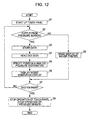
- the process flow of display control that the cellular phone unit according to this embodiment performs on the mouse pointer 33 on the basis of detected pressure values and the pressure distribution when a finger or the like makes contact with the touch panel 25 will be described below with the reference to a flowchart in FIG. 12 .
- the processes shown in the flowchart in FIG. 12 are performed by the control unit 10 executing the display control program stored in the program storing module 17 of the memory unit 16.
- the function of mouse pointer display control based on the above-mentioned detected pressure values and the pressure distribution can be set to either enabled or disabled, and when this function is set to enabled by a user, the processes in the flowchart in FIG. 12 are executed.
- the control unit 10 makes the touch panel control unit 24 start up the touch panel 25 (or pressure sensors) at step S1.
- control unit 10 makes the touch panel control unit 24 scan the pressure detecting blocks 35 of the touch panel unit 25 sequentially to monitor whether any pressure detecting block 35 is depressed at step S2.
- the detected pressure values from the pressure sensors are converted to pressure value data, and the pressure value data along with the coordinate value data of the pressure sensors are temporary stored in the data storing unit 18 of the memory unit 16 under the control of the control unit 10 at step S3.
- control unit 10 reads out the pressure value data and the coordinate value data stored in the data storing unit 18 at step S4.
- control unit 10 analyzes the pressure value data and the coordinate value data read out from the data storing unit 18 in order to specify the depressed position and to calculate the pressure distribution as mentioned above.
- control unit 10 makes the display control unit 15 display the mouse pointer on the display screen as mentioned above on the basis of the position and the pressure distribution calculated at step S5.
- step S7 the control unit 10 judges whether the power supply of the cellular phone unit is turned off or the function of mouse pointer display control is set to disabled. If either is not the case, the control unit 10 makes the process flow go back to step S2. On the other hand, if either is the case, the control unit 10 makes the process flow go to step S9.
- control unit 10 makes the touch panel control unit 24 stop the operation of the touch panel unit 25 (or stop the operation of the pressure sensors), and ends this display control processing.
- control unit 10 makes the display control unit 15 erase the display of the mouse pointer on the display screen as the process at step S8, and makes the process flow go to step S7. Meanwhile, once the mouse pointer is displayed, the mouse pointer can be left as it is when the user takes his/her finger or the like off the touch panel unit 25.
- a touch panel of pressure sensitive type with pressure sensors is taken as an example touch panel for a cellular phone unit according to the present invention
- the present invention can be applied to other types of touch panels.
- a resistive film type of touch panel a resistivity distribution analogous to the above-mentioned pressure distribution can be analyzed by detecting the contact position of a finger and measuring in detail the resistivity values of the parts with which the finger makes contact. Then the display of a mouse pointer can be controlled on the basis of the resistivity distribution like in the case of the pressure sensitive type.
- an electrostatic capacitor value distribution analogous to the above-mentioned pressure distribution can be analyzed by detecting the contact position of a finger and the parts of the panel surface whose electrostatic values have changed because of the close proximity of the finger and measuring in detail the electrostatic values of the above parts. Then the display of a mouse pointer can be controlled on the basis of the electrostatic capacitor value distribution like in the case of the pressure sensitive type.
- the display of a mouse pointer can be also controlled by performing detection analogous to the detection performed in the above electrostatic capacitor detecting type of touch panel.
- a distribution analogous to the above-mentioned pressure distribution can be analyzed by detecting the contact position of a finger and measuring differences among ultrasonic surface acoustic waves that change on the basis of the contact strengths shown by the parts with which the finger makes contact. Then the display of a mouse pointer can be controlled on the basis of the distribution like in the case of the pressure sensitive type.
- the display of a mouse pointer can be also controlled by performing detection analogous to the detection performed in the ultrasonic surface acoustic wave detecting type of touch panel. For other types of touch panels, explanations for them are omitted; however, if the analysis of the contact position and the corresponding distribution for each type of touch panel can be performed, the present invention can be applied to it.
- the cellular phone unit is configured to judge the position of a finger and the direction indicated by the finger by analyzing the position of the finger on the panel surface 30 of the touch panel 25 and the distribution of contacted parts of the position and display a mouse pointer 33 with its direction equal to the direction indicated by the finger. Therefore it becomes easy to operate the touch panel, and it is also ensured that desired icons and the like are touched.
- the present invention is one embodiment according to the present invention. Therefore it goes without saying that the present invention is not limited to the above-described embodiment and various modifications of the present invention depending on design requirements and other factors may be made without departing from the technical ideas relating to the present invention.
- the present invention can be applied not only to a cellular phone unit but also to various types of terminals - such as a PDA (personal digital assistant) equipped with a touch panel, a personal computer, a portable TV game machine, a portable digital television receiver, a car navigation terminal and the like.
- PDA personal digital assistant
Landscapes
- Engineering & Computer Science (AREA)
- General Engineering & Computer Science (AREA)
- Theoretical Computer Science (AREA)
- Human Computer Interaction (AREA)
- Physics & Mathematics (AREA)
- General Physics & Mathematics (AREA)
- Position Input By Displaying (AREA)
- Telephone Set Structure (AREA)
- User Interface Of Digital Computer (AREA)
Abstract
Description
- The present invention relates to an information display apparatus, mobile information unit, display control method and program.
- In recent years, various kinds of mobile devices such as a cellular phone unit, a portable music player and a PDA (personal digital assistant) that are equipped with a touch panel or a touch pad (both of them are referred to as a touch panel hereinafter) have been commercially produced. In addition, various types of touch panels such as those of a resistive film type, a pressure sensitive type, an electrostatic capacitor detecting type, an ultrasonic surface acoustic wave detecting type, an acoustic pulse recognition type, a vibration detecting type, an infrared light shielding type, an image recognition type and an electrostatic sensor type have been developed or commercially produced. The above-mentioned various types of touch panels are representative examples, and many other types have been also proposed. Because these types of touch panels may be produced using existing technologies, detailed explanation about these existing technologies is omitted.
- As another example, in Japanese Patent Application Publication No.
2000-347787 FIG. 1 thereof), a touch panel display apparatus, in which a pointer displayed on a display screen is controlled by the way the touch panel of the touch panel display apparatus is touched, has been disclosed. In other words, in the touch panel display apparatus described in Japanese Patent Application Publication No.2000-347787 - In Japanese Patent Application Publication No.
2005-128802 FIG. 7 thereof), a cellular phone unit in which a cursor displayed on a display screen is moved with the use of a pressure type pointing device that issues signals on the basis of a depressive force and a depressive direction. - Generally speaking, such a mobile device equipped with a touch panel as mentioned above displays several icons on its display screen, and the mobile device is configured to start an application program corresponding to an icon when a portion of panel corresponding to the display position of the icon is touched by a finger or the like.
- However, in the case where a user with large (or thick) fingers operates (or touches) a touch panel, it is often difficult for the user to touch (or depress) an icon depending on the display position of the icon. For example, if the user uses his/her right hand to operate the touch panel, it may be difficult for him/her to touch icons located on the lower right corner of the touch panel. For the same reason, if the user uses his/her left hand to operate the touch panel, it may be difficult for him/her to touch icons located on the lower left corner. Currently there is no technology to solve such an issue regarding a touch panel as mentioned above.
- In addition, when a user with large fingers operates a touch panel, there is a possibility that the user touches another icon other than the desired one or that the user touches plural icons. In this case, another application other than the desired one might start.
- Therefore, a user with large his fingers has to use a so-called stylus pen or the like to touch a desired icon in order to start a desired application. Alternatively, the user has to use another operation device (such as an arrow key) to start a desired application, and it is certain that these operations are very troublesome for the user.
- The present invention is proposed with the above mentioned actual situation in mind, and it provides an information display apparatus that makes the operation of its touch panel easy and enables a user to surely touch a desired icon and the like, a mobile information unit having the same function as the information display apparatus, a display control method and a display control program used therein.
- An information display apparatus according to an embodiment of the present invention includes a contact detecting panel unit that detects at least contact with the approximately transparent panel surface thereof made by an external object and a display panel unit installed on the panel back surface of the contact detecting panel unit. In addition, the information display apparatus according to the embodiment of the present invention includes an analyzing unit and a pointer control unit. In addition, the analyzing unit analyzes a contact position of the panel surface of the contact detecting panel unit with which the external object makes contact and a direction indicated by a specific portion of the external object on the basis of output values of the contact detecting panel unit. The pointer control unit also controls a display position and a pointing direction of a predefined pointer image displayed on the display panel unit on the basis of the contact position and the direction indicated by the specific portion, in which both the contact position and the direction indicated by the specific portion are obtained from the analyzing unit. Owing to the above configuration of the display control apparatus, the above-mentioned problems can be solved.
- To explain the embodiment of the present invention concretely, the display control apparatus finds the contact position of the panel surface of the contact detecting panel unit with which the external object makes contact and the direction indicated by the specific portion of the external object, and determines the display position and pointing direction of the predefined pointer image displayed on the display panel unit on the basis of the contact position and the direction indicated by the specific portion. In other words, a user makes a choice of his/her desired icon or the like by using the pointer image instead of directly touching the icon using his/her finger etc.
- The pointer control unit controls the display position of the predefined pointer image in the direction indicated by the specific portion and in the vicinity of the contact position, and at the same time the pointer control unit controls the pointing direction of the predefined pointer image on the basis of the direction indicated by the specific portion.
- To put it concretely, according to the embodiment of the present invention, the pointer image is displayed not in the position specified by the user's finger etc. but it is displayed in the direction indicated by the specific portion of the user's finger etc. and in the vicinity of the contact position of the user's finger etc. In addition, the pointing direction of the pointer image becomes identical to the direction indicated by the specific portion of the user's finger.
- In the embodiment of the present invention, the contact position on the panel surface of the contact detecting panel unit with which the external object makes contact and the direction indicated by a specific portion of the external object are calculated and the display position and the pointing direction of the pointer image displayed on the display panel unit is determined on the basis of the above-mentioned contact position and direction, so that it may be possible that even a user with thick fingers operates the touch panel easily and surely touches a desired icon and the like.
- Preferably, the information display apparatus is equipped with a touch panel that works as an input device for a user interface, that controls the display of a so-called mouse pointer on a display screen on the basis of input information from the touch panel.
- Various respective aspects and features of the invention are defined in the appended claims. Combinations of features from the dependent claims may be combined with features of the independent claims as appropriate and not merely as explicitly set out in the claims.
- Embodiments of the invention will now be described with reference to the accompanying drawings, throughout which like parts are referred to by like references, and in which:
-
FIG. 1 is a block diagram showing an internal schematic configuration of a cellular phone unit according to an embodiment of the present invention; -
FIG. 2 is a diagram showing an example of a schematic contact pressure distribution when a finger makes contact with a panel surface of a touch panel unit; -
FIG. 3 is a diagram showing an enlarged view of the finger and the pressure distribution inFIG. 2 ; -
FIG. 4 is a diagram showing plural pressure detecting blocks disposed on the touch panel and an example of schematic contact pressure distribution when the finger makes contact with the panel surface; -
FIG. 5 is a diagram used to explain the relation between the direction indicated by the finger and the direction of a mouse pointer on the display screen when the finger is placed on the lower right part of the panel surface and its fingertip points in the direction from the lower part of the panel surface to the upper left; -
FIG. 6 is a diagram used to explain the relation between the direction indicated by the finger and the direction of the mouse pointer on the display screen when the finger is placed nearly on the middle part of the panel surface and the fingertip points in the direction from the upper left part of the panel surface to the lower right; -
FIG. 7 is a diagram used to explain the control of the display of shifting of the mouse pointer when the finger moves to the right after the finger is placed slightly to the left side of the middle part of the panel surface; -
FIG. 8 is a diagram used to explain the control over the display of the rotation of the mouse pointer when the fingertip rotates clockwise while the contact position of the finger does not move after the finger is placed nearly on the middle part of the panel surface; -
FIG. 9 is a diagram used to explain an example of contact pressure distribution when the finger is placed nearly at a right angle to the panel surface; -
FIG. 10 is a diagram used to explain the case where only the pressure distribution changes while the contact position of the finger on the panel surface and the direction indicated by the fingertip do not change; -
FIG. 11 is a diagram used to explain the case where only the pressure distribution changes while the contact position of the finger on the panel surface and the direction indicated by the fingertip do not change, and the display of the mouse pointer is controlled on the basis of the change of the pressure distribution; and -
FIG. 12 is a flowchart showing the process flow of display control that the cellular phone unit according to this embodiment performs on themouse pointer 33 on the basis of detected pressure values detected by the touch panel unit and the pressure distribution calculated from the detected pressure values. - A preferred embodiment of the present invention will be described hereinafter with reference to the attached drawings.
- In this embodiment, a cellular phone unit equipped with a touch panel of a pressure sensitive type that uses pressure sensors is taken as an example apparatus to which the present invention is applied. Therefore, the contents described hereinafter are only those regarding the preferred embodiment, and it goes without saying that the present invention is not limited to this specific embodiment. The present invention can be applied to various types of touch panels such as those of a resistive film type, an electrostatic capacitor detecting type, an ultrasonic surface acoustic wave detecting type, an acoustic pulse recognition type, a vibration detecting type, an infrared light shielding type, an image recognition type and an electrostatic sensor type.
-
FIG. 1 is a block diagram showing an internal schematic configuration of a cellular phone unit according to this embodiment of the present invention. - In
FIG. 1 , acommunication antenna 12 and acommunication circuit 11 are used for transmission and reception of signal waves of phone calls and packet communication; and frequency conversion, modulation, demodulation and the like of transmitter and receiver signals. - A
speaker 20 is composed of a phone call receiving speaker for the cellular phone unit and a speaker for alarm sounds, played-back music, etc. Amicrophone 21 is used for phone call transmission and collection of external sounds. Asound processing unit 22 performs various types of processes regarding phone call data, the sounds of played-back music, etc. - An
operating unit 13 is composed of various operating parts such as a numeric keypad, a call key, an end/power key, an arrow key, a shutter button, a jog dial, etc. that are all mounted on the chassis (not shown) of the cellular phone unit, and an operating signal generator that, when an operating part is operated, generates a signal corresponding to the operating part. Meanwhile, the functions of some keys, buttons, etc. of theoperating unit 13 can be assigned to atouch panel unit 25, and then these keys, buttons, etc. can be omitted. - A
display unit 14 is a display device composed of, for example, a liquid crystal display panel or an organic EL display panel. Adisplay control unit 15 controls a display driving circuit of thedisplay unit 14 to display characters, symbols, icons, a mouse pointer, still images, moving images and the like on the display screen of thedisplay unit 14. Animage processing unit 23 performs various processes such as generating display image data for characters, symbols, still images, moving images and the like to be displayed on the display screen of thedisplay unit 14. Meanwhile, the functions of thedisplay control unit 15 can be performed by acontrol unit 10. - A
memory unit 16 stores, for example, an OS (operating system) program, various application programs such as a control program that thecontrol unit 10 uses to control other units, a display control program for controlling the display of a mouse pointer etc. on the basis of the operation of a touch panel, and other various data. The display control of the mouse pointer etc. based on the operation of the touch panel according to an embodiment of the present invention will be described later. Thememory unit 16 also stores necessary data and serves as a working area for thecontrol unit 10. Meanwhile, aprogram storing module 17 of thememory unit 16 stores various application programs relating to the embodiment of the present invention such as the display control program and adata storing module 18 stores various data including parameters and threshold values etc. used by the display control program. Meanwhile, various programs, which are stored in thememory unit 16 and relate to the embodiment of the present invention including the display control program, can be stored in thememory unit 16 via disk type storage media, external semiconductor memories, or via external storage media through cables or wireless networks using external interfaces. - The
touch panel unit 25 includes an approximately transparent panel that is disposed on the display panel surface of thedisplay unit 14. The panel is a touch panel of a pressure sensitive type equipped with pressure sensors. Although the details will be described hereinafter, when an external object such as a user's finger applies pressure on the panel surface of thetouch panel unit 25, thetouch panel unit 25 detects the pressure and generates and outputs numerical values representing the applied pressure (pressure value signals). The panel surface of thetouch panel unit 25 is divided into plural minute pressure detecting blocks, and each pressure detecting block has a pressure sensor. Output signals from these pressure sensors are sent to a touchpanel control unit 24. - The touch
panel control unit 24 performs the start-up control (activation ON/OFF control) of the pressure sensors of thetouch panel unit 25, and an analog-to-digital conversion in which the pressure value signals sent from activated pressure sensors are converted into pressure value data. The touchpanel control unit 24 also performs position detecting processing in which the coordinate values on the panel for pressure-applied pressure sensors are generated. To put it concretely, the touchpanel control unit 24 detects the positions on the touch panel at which the pressure-applied pressure sensors or pressure applied-pressure detecting blocks are disposed as coordinate values. - The
control unit 10 includes a CPU (central processing unit), and performs control of the units, various signal processing controls, etc. of the cellular phone unit according to this embodiment of the present invention. In this embodiment of the present invention, it is worth noting that thecontrol unit 10 executes the display control program stored in theprogram storing module 17 of thememory unit 16, and performs various accompanying data processing tasks. The details will be described hereinafter. - Although they are not shown in
FIG. 1 , the cellular phone unit according to this embodiment is equipped with various component parts that an ordinary cellular phone unit has. - When the user's finger or the like makes contact with the surface of the
touch panel unit 25 as an external object, the finger or the like makes contact with some of the minute pressure detecting blocks. Therefore pressure values are detected from the plural pressure detecting blocks with which the finger or the like makes contact. - In addition, the pressure values detected from those pressure detecting blocks are different from each other because all the pressures caused by the contact portions of the finger or the like are not equal. In other words, when a finger or the like makes contact with the panel surface, there are various contact pressures from large ones to small ones.
- Therefore, if these different pressure values detected from the plural pressure detecting blocks with which the finger or the like makes contact are analyzed, the pressure distribution caused by the finger or the like which makes contact with the panel surface can be obtained.
- Then if the pressure distribution caused by the finger or the like is known, it becomes possible to extrapolate the direction indicated by a specific portion of the finger (, for example the fingertip) on the panel surface.
- Generally speaking, if a finger is placed in contact with a plane surface, the pressure applied to the plane surface by the fingertip is the largest and the pressure applied by a portion of the finger gradually decreases as the portion gets closer to the base of the finger.
- As a result, if a pressure distribution caused by a finger is analyzed, it becomes possible to extrapolate the direction indicated by the fingertip.
- In the cellular phone unit according to this embodiment, if a finger makes contact with some of pressure detecting blocks, the
control unit 10 analyzes a pressure distribution caused by the finger as mentioned above using output signals from the touchpanel control unit 24, and detects the direction indicated by the fingertip. -
FIG. 2 is an example of a schematiccontact pressure distribution 40 when afinger 32 shown by dotted lines makes contact with apanel surface 30 of thetouch panel unit 25.FIG. 3 shows an enlarged view of thepressure distribution 40 inFIG. 2 . InFIG. 3 , intensities of the pressures are represented bypressure distribution lines pressure distribution line 40a represents an area with the largest degree of pressure, the area between thepressure distribution line pressure distribution line 40b and40c represents an area with the third largest degree of pressure, and the area between thepressure distribution line pressure distribution line 40d represents an area with the degree of pressure of nearly zero because the finger does not make contact with the area. - As can be judged from
FIG. 2 and FIG. 3 , if afinger 32 makes contact with thepanel surface 30, the pressure distribution caused by thefinger 32 shows that the pressure applied to the plane surface by thefingertip 32a is the largest and the pressure applied by a portion of the finger gradually decreases as the portion gets closer to the base of thefinger 32b. -
FIG. 4 shows pluralpressure detecting blocks 35 disposed on thetouch panel 25 and an example of schematiccontact pressure distribution 40 when thefinger 32 makes contact with thepanel surface 30. InFIG. 4 , although the sizes (areas) ofpressure detecting blocks 35 are depicted as being larger than they actually are for illustration purposes, they are really far smaller than the sizes (areas) ofpressure detecting blocks 35 depicted inFIG. 4 . - In this embodiment, the touch
panel control unit 24 scans thepressure detecting blocks 35 disposed on thepanel surface 30 sequentially as indicated by arrows inFIG. 4 , and when detecting apressure detecting block 35 whose sensor outputs some pressure value, the touchpanel control unit 24 performs more detailed pressure detection regarding pressure detecting blocks surrounding thepressure detecting block 35 whose sensor outputs the pressure value. - Then the
control unit 10 calculates thepressure distribution 40 by analyzing the magnitudes of pressure values obtained from thepressure detecting blocks 35, and detects the direction indicated by the fingertip of thefinger 32 on the basis of thepressure distribution 40. - The cellular phone unit according to this embodiment is configured to control the pointing direction indicated by a mouse pointer, for example, displayed on the display screen on the basis of the direction indicated by the fingertip of the
finger 32 when the cellular phone unit detects the direction indicated by the fingertip on the basis of the pressure distribution caused by thefinger 32 that makes contact with the above-mentionedpanel surface 30. - In
FIG. 5 andFIG. 6 , the above-mentionedpanel surface 30, image examples displayed on the display screen at the lower part of thepanel surface 30, and thefinger 32 that makes contact with thepanel surface 30 are shown. - To put it concretely, as shown in
FIG. 5 andFIG. 6 , the cellular phone unit according to this embodiment detects the contact position of the finger 32 (the position on thepanel surface 30 with which thefinger 32 makes contact) when thefinger 32 makes contact with thepanel surface 30, and at the same time detects the direction indicated by the fingertip on the basis of the pressure distribution caused by thefinger 32. Then, on the basis of the detected contact position and the detected direction indicated by the fingertip, the cellular phone unit controls the display position of themouse pointer 33 and the direction indicated by the arrow of the mouse pointer. -
FIG. 5 shows the case where thefinger 32 is placed on the right lower part of thepanel surface 30 and the fingertip shows the direction from the lower part of the panel surface to the upper left. InFIG. 5 , thecontrol unit 10 performs display control so that themouse pointer 33 is displayed in the position that is judged from thepressure distribution 40 to be both in the direction of the fingertip and in the vicinity of the fingertip and at the same time the arrow of the mouse pointer shows the direction from the lower right part of the panel surface to the upper left on the basis of thepressure distribution 40. -
FIG. 6 shows the case where thefinger 32 is placed nearly on the middle part of thepanel surface 30 and the fingertip shows the direction from the upper left part of the panel surface to the lower right. InFIG. 6 , thecontrol unit 10 performs display control so that themouse pointer 33 is displayed in the position that is judged from thepressure distribution 40 to be both in the direction of the fingertip and in the vicinity of the fingertip and at the same time the arrow of the mouse pointer shows the direction from the upper left part of the panel surface to the lower right on the basis of thepressure distribution 40. - Therefore, if the user wants to select an icon located on the lower right corner of the icons displayed on the display screen for example, he has only to put his finger in the direction from upper left to lower right on the display screen as shown in
FIG. 6 . According to the example shown inFIG. 6 , even if the finger of the user is thick and it's difficult for the user to touch the icon directly on the lower right corner for example, the user can select the icon easily. - In addition, the reason why the
mouse pointer 33 is displayed in the position that is judged from thepressure distribution 40 to be both in the direction of the fingertip and in the vicinity of the fingertip is that attention is paid lest themouse pointer 33 should be hidden by thefinger 32 with consideration given to the fact that the fingertip is commonly used by the user to point at something. - The cellular phone unit according to this embodiment is configured to control the
mouse pointer 33 so that themouse pointer 33 moves along with the movement of thefinger 32 when thefinger 32 moves along thepanel surface 30. -
FIG. 7 andFIG. 8 show the relation among thepanel surface 30, thefinger 32 that makes contact with thepanel surface 30, and themouse pointer 33 displayed on the display screen. - To put it concretely, as shown in
FIG. 7 andFIG. 8 , the cellular phone unit according to this embodiment detects the change of the contact position of thefinger 32 and the change of the pressure distribution along with the movement of thefinger 32 when thefinger 32 moves while keeping contact with thepanel surface 30. Then, on the basis of the detected change of the contact position and the detected change of the pressure distribution, the cellular phone unit controls the display position of themouse pointer 33 and the direction indicated by the arrow of themouse pointer 33. -
FIG. 7 shows the case where thefinger 32 moves to the right while keeping contact with thepanel surface 30 after thefinger 32 is placed slightly to the left side of the middle part of thepanel surface 30. InFIG. 7 , when the pressure distribution moves from thepressure distribution 40e to 40f as the finger of the user moves from thefinger 32a to 32b, the display of themouse pointer 33 is controlled so that it moves from the left side of the middle part of thepanel surface 30 to the right side, that is, in the direction from themouse pointer 33a to 33b, along with the movement of thepressure distribution 40. -
FIG. 8 shows the case where the fingertip rotates clockwise while the contact position of thefinger 32 does not move after thefinger 32 is placed nearly on the middle part of thepanel surface 30. InFIG. 8 , when the pressure distribution rotates from thepressure distribution finger mouse pointer 33 is controlled so that it rotates clockwise on the middle part of thepanel surface 30 or the direction indicated by the arrow of the mouse pointer rotates clockwise on the basis of the rotation of thepressure distribution 40. - The cellular phone unit according to this embodiment is configured to judge that the user is directly pointing at the contact position of the
finger 32 if the contact pressure distribution caused by thefinger 32 is not biased unlike the contact distribution shown inFIG. 2 or FIG. 3 while thefinger 32 keeps contact with thepanel surface 30. - To put it concretely, if the contact pressure distribution is nearly balanced when the
finger 32 is placed nearly at the right angle to thepanel surface 30 as shown inFIG. 9 , it is judged that the user is directly pointing at the contact position of thefinger 32. In this case, themouse pointer 33 may be displayed or not displayed, either is acceptable. - The cellular phone unit according to this embodiment is also configured to perform display control so that, when neither the contact position of the
finger 32 nor the direction indicated by the fingertip changes on thepanel surface 30 but only the contact pressure distribution changes, the position, the length/shape or the like of themouse pointer 33 is changed on the basis of the pressure distribution. -
FIG. 10 and FIG. 11 show the case where the pressure distribution is changed by changing the angle between thefinger 32 and thepanel surface 30 while the contact position of thefinger 32 on thepanel surface 30 and the direction indicated by the fingertip do not change. - To put it concretely, as shown in
FIG. 10 and FIG. 11 , the cellular phone unit according to this embodiment controls the display position, the length, the shape or the like of themouse pointer 33 on the basis of the change of the pressure distribution when the pressure distribution changes from thepressure distribution 40j to 40k by changing the angle of thefinger 32 from that of thefinger 32a to 32b while the contact position of thefinger 32 on thepanel surface 30 and the direction indicated by the fingertip do not change. -
FIG. 10 and FIG. 11 show an example of display control of themouse pointer 33 in which the pressure distribution caused by thefinger 32 changes from thepressure distribution 40j to 40k due to the angle between thefinger 32 and thepanel surface 30 changing from the large angle between thefinger 32a and the panel surface as shown by a dashed line inFIG. 10 to the small angle between thefinger 32b and the panel surface as shown by a solid line inFIG. 10 . - In addition,
FIG. 11 shows an example of display control in which the display position of themouse pointer 33a shown by a dashed line is changed to the display position of themouse pointer 33b shown by a solid line on the basis of the above-mentioned change of the pressure distribution. - Although
FIG. 11 shows the example in which the display position of themouse pointer 33 is changed, the length or shape of themouse pointer 33 can be changed on the basis of the change of the pressure distribution. - In addition to one above, it may be also possible to perform display control in which the
mouse pointer 33 is made thick and short when the angle between thefinger 32a and thepanel surface 30 is large as shown in a dashed line inFIG. 10 , and themouse pointer 33 is made thin and long when the angle between thefinger 32b and thepanel surface 30 is small as shown in a solid line inFIG. 10 . - The process flow of display control that the cellular phone unit according to this embodiment performs on the
mouse pointer 33 on the basis of detected pressure values and the pressure distribution when a finger or the like makes contact with thetouch panel 25 will be described below with the reference to a flowchart inFIG. 12 . The processes shown in the flowchart inFIG. 12 are performed by thecontrol unit 10 executing the display control program stored in theprogram storing module 17 of thememory unit 16. In addition, in the cellular phone unit according to this embodiment, the function of mouse pointer display control based on the above-mentioned detected pressure values and the pressure distribution can be set to either enabled or disabled, and when this function is set to enabled by a user, the processes in the flowchart inFIG. 12 are executed. - In
FIG. 12 , if the cellular phone unit is started up by its power supply being turned on when the function of the mouse pointer display control has been already enabled, or if the function of the mouse pointer display control is set from disabled to enabled when the cellular phone unit has been already started up, thecontrol unit 10 makes the touchpanel control unit 24 start up the touch panel 25 (or pressure sensors) at step S1. - Then the
control unit 10 makes the touchpanel control unit 24 scan thepressure detecting blocks 35 of thetouch panel unit 25 sequentially to monitor whether anypressure detecting block 35 is depressed at step S2. - If detected pressure values are obtained from any pressure sensors in the monitoring process at step S2, the detected pressure values from the pressure sensors are converted to pressure value data, and the pressure value data along with the coordinate value data of the pressure sensors are temporary stored in the
data storing unit 18 of thememory unit 16 under the control of thecontrol unit 10 at step S3. - Next, the
control unit 10 reads out the pressure value data and the coordinate value data stored in thedata storing unit 18 at step S4. - At step S5, the
control unit 10 analyzes the pressure value data and the coordinate value data read out from thedata storing unit 18 in order to specify the depressed position and to calculate the pressure distribution as mentioned above. - Then at step S6, the
control unit 10 makes thedisplay control unit 15 display the mouse pointer on the display screen as mentioned above on the basis of the position and the pressure distribution calculated at step S5. - Next at step S7, the
control unit 10 judges whether the power supply of the cellular phone unit is turned off or the function of mouse pointer display control is set to disabled. If either is not the case, thecontrol unit 10 makes the process flow go back to step S2. On the other hand, if either is the case, thecontrol unit 10 makes the process flow go to step S9. - At step S9, the
control unit 10 makes the touchpanel control unit 24 stop the operation of the touch panel unit 25 (or stop the operation of the pressure sensors), and ends this display control processing. - If any detected pressure values have not been obtained from any pressure sensors in the monitoring process at step S2 or if the user has not made contact with the
touch panel unit 25, thecontrol unit 10 makes thedisplay control unit 15 erase the display of the mouse pointer on the display screen as the process at step S8, and makes the process flow go to step S7. Meanwhile, once the mouse pointer is displayed, the mouse pointer can be left as it is when the user takes his/her finger or the like off thetouch panel unit 25. - In the above-mentioned embodiment, although a touch panel of pressure sensitive type with pressure sensors is taken as an example touch panel for a cellular phone unit according to the present invention, the present invention can be applied to other types of touch panels. For example, for a resistive film type of touch panel, a resistivity distribution analogous to the above-mentioned pressure distribution can be analyzed by detecting the contact position of a finger and measuring in detail the resistivity values of the parts with which the finger makes contact. Then the display of a mouse pointer can be controlled on the basis of the resistivity distribution like in the case of the pressure sensitive type. As for an electrostatic capacitor detecting type of touch panel, an electrostatic capacitor value distribution analogous to the above-mentioned pressure distribution can be analyzed by detecting the contact position of a finger and the parts of the panel surface whose electrostatic values have changed because of the close proximity of the finger and measuring in detail the electrostatic values of the above parts. Then the display of a mouse pointer can be controlled on the basis of the electrostatic capacitor value distribution like in the case of the pressure sensitive type. For an electrostatic sensor type of touch panel, the display of a mouse pointer can be also controlled by performing detection analogous to the detection performed in the above electrostatic capacitor detecting type of touch panel. For an ultrasonic surface acoustic wave detecting type of touch panel, a distribution analogous to the above-mentioned pressure distribution can be analyzed by detecting the contact position of a finger and measuring differences among ultrasonic surface acoustic waves that change on the basis of the contact strengths shown by the parts with which the finger makes contact.
Then the display of a mouse pointer can be controlled on the basis of the distribution like in the case of the pressure sensitive type. In addition, for an acoustic pulse recognition type of touch panel, the display of a mouse pointer can be also controlled by performing detection analogous to the detection performed in the ultrasonic surface acoustic wave detecting type of touch panel. For other types of touch panels, explanations for them are omitted; however, if the analysis of the contact position and the corresponding distribution for each type of touch panel can be performed, the present invention can be applied to it. - As described above, the cellular phone unit according to this embodiment of the present invention is configured to judge the position of a finger and the direction indicated by the finger by analyzing the position of the finger on the
panel surface 30 of thetouch panel 25 and the distribution of contacted parts of the position and display amouse pointer 33 with its direction equal to the direction indicated by the finger. Therefore it becomes easy to operate the touch panel, and it is also ensured that desired icons and the like are touched. - The above-described embodiment of the present invention is one embodiment according to the present invention. Therefore it goes without saying that the present invention is not limited to the above-described embodiment and various modifications of the present invention depending on design requirements and other factors may be made without departing from the technical ideas relating to the present invention. In addition, the present invention can be applied not only to a cellular phone unit but also to various types of terminals - such as a PDA (personal digital assistant) equipped with a touch panel, a personal computer, a portable TV game machine, a portable digital television receiver, a car navigation terminal and the like.
- In so far as the embodiments of the invention described above are implemented, at least in part, using software-controlled data processing apparatus, it will be appreciated that a computer program providing such software control and a transmission, storage or other medium by which such a computer program is provided are envisaged as aspects of the present invention.
Claims (10)
- An information display apparatus comprising:a contact detecting panel unit that detects at least contact with the approximately transparent panel surface thereof made by an external object;a display panel unit installed on the panel back surface of the contact detecting panel unit;an analyzing unit that analyzes a contact position of the panel surface with which the external object makes contact and a direction indicated by a specific portion of the external object on the basis of output values from the contact detecting panel unit; anda pointer control unit that controls a display position and a pointing direction of a predefined pointer image displayed on the display panel unit on the basis of the contact position and the direction indicated by the specific portion, wherein both the contact position and the direction are obtained from the analyzing unit.
- The information display apparatus according to claim 1, wherein the pointer control unit controls the display position of the predefined pointer image in the direction indicated by the specific portion and in the vicinity of the contact position, and at the same time the pointer control unit controls a pointing direction of the predefined pointer image on the basis of the direction indicated by the specific portion.
- The information display apparatus according to any of claims 1 and 2, wherein the analyzing unit calculates an output value distribution obtained from the contact portion of the panel surface with which the external object makes contact on the basis of the output values of the contact detecting panel unit and analyzes the direction indicated by the specific portion on the basis of the output value distribution.
- The information display apparatus according to claims 1, wherein:the analyzing unit analyzes a variation of the contact position on the basis of the output values of the contact detecting panel unit; andthe pointer control unit changes the display position of the predefined pointer image displayed on the display panel unit on the basis of the variation of the contact position obtained by the analyzing unit.
- The information display apparatus according to claims 1, wherein:the analyzing unit analyzes a variation of the direction indicated by the specific portion on the basis of the output values of the contact detecting panel unit; andthe pointer control unit changes the pointing direction of the predefined pointer image displayed on the display panel unit on the basis of the variation of the direction indicated by the specific portion that is obtained from the analyzing unit.
- The information display apparatus according to claims 1, wherein:the analyzing unit analyzes a variation of the contact position and a variation of the direction indicated by the specific portion on the basis of the output values of the contact detecting panel unit; andthe pointer control unit changes the display position of the predefined pointer image displayed on the display panel unit on the basis of the variation of the contact position obtained from the analyzing unit and changes the pointing direction of the predefined pointer image displayed on the display panel unit on the basis of the variation of the direction indicated by the specific portion.
- The information display apparatus according to claims 1, wherein:the contact detecting panel unit has a plurality of pressure sensors that detect a plurality of contact pressures on the panel surface applied by the external object; andthe analyzing unit analyzes the contact position and the direction indicated by the specific portion of the external object on the basis of the output values obtained from the plurality of pressure sensors of the contact detecting panel unit.
- A mobile information unit comprising:a contact detecting panel unit that detects at least contact with the approximately transparent panel surface thereof made by an external object;a display panel unit installed on the panel back surface thereof;an analyzing unit that analyzes a contact position of the panel surface of the contact detecting panel unit with which the external object makes contact and a direction indicated by a specific portion of the external object on the basis of output values of the contact detecting panel unit; anda pointer control unit that controls the display position and pointing direction of a predefined pointer image displayed on the display panel unit on the basis of the contact position and the direction indicated by the specific portion, wherein both the contact position and the direction indicated by the specific portion are obtained from the analyzing unit.
- A display control method comprising the steps of:causing an analyzing unit to analyze a contact position of the approximately transparent panel surface of a contact detecting panel unit with which an external object makes contact and a direction indicated by a specific portion of the external object on the basis of output values of the contact detecting panel unit, wherein the contact detecting panel unit detects at least contact with the panel surface made by the external object; andcausing a pointer control unit to control a display position and a pointing direction of a predefined pointer image displayed on a display panel unit installed on the panel back surface of the contact detecting panel unit on the basis of the contact position and the direction indicated by the specific portion, wherein both the contact position and the direction indicated by the specific portion are obtained from the analyzing unit.
- A display control program that causes a computer to function as:an analyzing unit that analyzes a contact position of the approximately transparent panel surface of a contact detecting panel unit with which an external object makes contact and a direction indicated by a specific portion of the external object on the basis of output values of the contact detecting panel unit, wherein the contact detecting panel unit detects at least contact with the panel surface thereof made by the external object; anda pointer control unit that controls a display position and a pointing direction of a predefined pointer image displayed on the display panel unit installed on the panel back surface of the contact detecting panel unit on the basis of the contact position and the direction indicated by the specific portion, wherein both the contact position and the direction indicated by the specific portion are obtained from the analyzing unit.
Applications Claiming Priority (1)
| Application Number | Priority Date | Filing Date | Title |
|---|---|---|---|
| JP2008272780A JP2010102474A (en) | 2008-10-23 | 2008-10-23 | Information display device, personal digital assistant, display control method, and display control program |
Publications (2)
| Publication Number | Publication Date |
|---|---|
| EP2184672A1 true EP2184672A1 (en) | 2010-05-12 |
| EP2184672B1 EP2184672B1 (en) | 2014-06-11 |
Family
ID=41508787
Family Applications (1)
| Application Number | Title | Priority Date | Filing Date |
|---|---|---|---|
| EP09252461.0A Not-in-force EP2184672B1 (en) | 2008-10-23 | 2009-10-22 | Information display apparatus, mobile information unit, display control method and display control program |
Country Status (4)
| Country | Link |
|---|---|
| US (1) | US8599131B2 (en) |
| EP (1) | EP2184672B1 (en) |
| JP (1) | JP2010102474A (en) |
| CN (1) | CN101727238B (en) |
Cited By (4)
| Publication number | Priority date | Publication date | Assignee | Title |
|---|---|---|---|---|
| WO2016077414A1 (en) * | 2014-11-11 | 2016-05-19 | Qualcomm Incorporated | System and methods for controlling a cursor based on finger pressure and direction |
| WO2016209687A1 (en) * | 2015-06-26 | 2016-12-29 | Microsoft Technology Licensing, Llc | Selective pointer offset for touch-sensitive display device |
| RU2729939C2 (en) * | 2016-01-27 | 2020-08-13 | Стериале Сосьедад Анонима | System for placing medical waste with a package and a machine for making such a package |
| US10786733B2 (en) | 2015-09-29 | 2020-09-29 | Tencent Technology (Shenzhen) Company Limited | Information processing method, terminal, and computer storage medium for releasing virtual skill object based on user gesture |
Families Citing this family (19)
| Publication number | Priority date | Publication date | Assignee | Title |
|---|---|---|---|---|
| JP2012252652A (en) * | 2011-06-06 | 2012-12-20 | Panasonic Corp | Touch panel input device |
| KR101189633B1 (en) * | 2011-08-22 | 2012-10-10 | 성균관대학교산학협력단 | A method for recognizing ponter control commands based on finger motions on the mobile device and a mobile device which controls ponter based on finger motions |
| JP5576571B2 (en) * | 2011-10-11 | 2014-08-20 | インターナショナル・ビジネス・マシーンズ・コーポレーション | Object indication method, apparatus, and computer program |
| US9671880B2 (en) * | 2011-12-22 | 2017-06-06 | Sony Corporation | Display control device, display control method, and computer program |
| JP6015183B2 (en) | 2012-07-18 | 2016-10-26 | 富士ゼロックス株式会社 | Information processing apparatus and program |
| JP5388246B1 (en) | 2012-08-31 | 2014-01-15 | Necシステムテクノロジー株式会社 | INPUT DISPLAY CONTROL DEVICE, THIN CLIENT SYSTEM, INPUT DISPLAY CONTROL METHOD, AND PROGRAM |
| TW201413515A (en) * | 2012-09-26 | 2014-04-01 | Hon Hai Prec Ind Co Ltd | Display device, touching control device and method for controlling display device |
| JP5798103B2 (en) * | 2012-11-05 | 2015-10-21 | 株式会社Nttドコモ | Terminal device, screen display method, program |
| JP6033061B2 (en) * | 2012-11-30 | 2016-11-30 | Kddi株式会社 | Input device and program |
| JP2014123257A (en) * | 2012-12-21 | 2014-07-03 | Nippon Seiki Co Ltd | Input device for vehicle |
| CN103902206B (en) * | 2012-12-25 | 2017-11-28 | 广州三星通信技术研究有限公司 | The method and apparatus and mobile terminal of mobile terminal of the operation with touch-screen |
| US20150186011A1 (en) * | 2013-12-30 | 2015-07-02 | Samsung Electronics Co., Ltd. | Apparatus and method for interacting with items on a portable terminal |
| JP6260469B2 (en) * | 2014-06-25 | 2018-01-17 | 富士通株式会社 | Data sequence selection method, data sequence selection program, and portable terminal |
| KR101622695B1 (en) | 2014-09-12 | 2016-05-19 | 엘지전자 주식회사 | Mobile terminal and control method for the mobile terminal |
| CN105630365A (en) * | 2014-10-29 | 2016-06-01 | 深圳富泰宏精密工业有限公司 | Webpage adjustment method and system |
| CN106293438A (en) * | 2015-06-04 | 2017-01-04 | 北京智谷睿拓技术服务有限公司 | Method of mapping, device and subscriber equipment |
| JP6500180B2 (en) * | 2015-08-20 | 2019-04-17 | 株式会社Joled | Image processing apparatus, display apparatus and electronic device |
| JP2017102051A (en) * | 2015-12-03 | 2017-06-08 | ニッタ株式会社 | Pressure measuring device and pressure measuring program |
| US20180121000A1 (en) * | 2016-10-27 | 2018-05-03 | Microsoft Technology Licensing, Llc | Using pressure to direct user input |
Citations (3)
| Publication number | Priority date | Publication date | Assignee | Title |
|---|---|---|---|---|
| GB2347200A (en) * | 1999-02-24 | 2000-08-30 | Ibm | Intuitive cursor moving method and device for touch sensitive pads |
| JP2000347787A (en) | 1999-06-09 | 2000-12-15 | Victor Co Of Japan Ltd | Touch panel display device |
| JP2005128802A (en) | 2003-10-23 | 2005-05-19 | Sony Ericsson Mobilecommunications Japan Inc | Portable electronic device |
Family Cites Families (6)
| Publication number | Priority date | Publication date | Assignee | Title |
|---|---|---|---|---|
| US5621438A (en) * | 1992-10-12 | 1997-04-15 | Hitachi, Ltd. | Pointing information processing apparatus with pointing function |
| JPH06301486A (en) * | 1993-04-16 | 1994-10-28 | Hitachi Ltd | Pointing device and input / output integrated information processing device |
| US6995752B2 (en) * | 2001-11-08 | 2006-02-07 | Koninklijke Philips Electronics N.V. | Multi-point touch pad |
| JP4860625B2 (en) * | 2004-10-08 | 2012-01-25 | イマージョン コーポレーション | Haptic feedback for simulating buttons and scrolling motion on touch input devices |
| US7605804B2 (en) * | 2005-04-29 | 2009-10-20 | Microsoft Corporation | System and method for fine cursor positioning using a low resolution imaging touch screen |
| US20070097096A1 (en) * | 2006-03-25 | 2007-05-03 | Outland Research, Llc | Bimodal user interface paradigm for touch screen devices |
-
2008
- 2008-10-23 JP JP2008272780A patent/JP2010102474A/en active Pending
-
2009
- 2009-10-22 EP EP09252461.0A patent/EP2184672B1/en not_active Not-in-force
- 2009-10-22 US US12/603,611 patent/US8599131B2/en not_active Expired - Fee Related
- 2009-10-23 CN CN200910205441.4A patent/CN101727238B/en not_active Expired - Fee Related
Patent Citations (3)
| Publication number | Priority date | Publication date | Assignee | Title |
|---|---|---|---|---|
| GB2347200A (en) * | 1999-02-24 | 2000-08-30 | Ibm | Intuitive cursor moving method and device for touch sensitive pads |
| JP2000347787A (en) | 1999-06-09 | 2000-12-15 | Victor Co Of Japan Ltd | Touch panel display device |
| JP2005128802A (en) | 2003-10-23 | 2005-05-19 | Sony Ericsson Mobilecommunications Japan Inc | Portable electronic device |
Cited By (4)
| Publication number | Priority date | Publication date | Assignee | Title |
|---|---|---|---|---|
| WO2016077414A1 (en) * | 2014-11-11 | 2016-05-19 | Qualcomm Incorporated | System and methods for controlling a cursor based on finger pressure and direction |
| WO2016209687A1 (en) * | 2015-06-26 | 2016-12-29 | Microsoft Technology Licensing, Llc | Selective pointer offset for touch-sensitive display device |
| US10786733B2 (en) | 2015-09-29 | 2020-09-29 | Tencent Technology (Shenzhen) Company Limited | Information processing method, terminal, and computer storage medium for releasing virtual skill object based on user gesture |
| RU2729939C2 (en) * | 2016-01-27 | 2020-08-13 | Стериале Сосьедад Анонима | System for placing medical waste with a package and a machine for making such a package |
Also Published As
| Publication number | Publication date |
|---|---|
| CN101727238B (en) | 2014-11-19 |
| US20100103097A1 (en) | 2010-04-29 |
| EP2184672B1 (en) | 2014-06-11 |
| JP2010102474A (en) | 2010-05-06 |
| CN101727238A (en) | 2010-06-09 |
| US8599131B2 (en) | 2013-12-03 |
Similar Documents
| Publication | Publication Date | Title |
|---|---|---|
| EP2184672B1 (en) | Information display apparatus, mobile information unit, display control method and display control program | |
| US10871892B2 (en) | Input device | |
| KR100537280B1 (en) | Apparatus and method for inputting character using touch screen in portable terminal | |
| JP5295328B2 (en) | User interface device capable of input by screen pad, input processing method and program | |
| US8918146B2 (en) | Automatic gain control based on detected pressure | |
| KR102120930B1 (en) | User input method of portable device and the portable device enabling the method | |
| KR100663437B1 (en) | Remote input method using fingerprint sensor | |
| JP5759660B2 (en) | Portable information terminal having touch screen and input method | |
| US20100146459A1 (en) | Apparatus and Method for Influencing Application Window Functionality Based on Characteristics of Touch Initiated User Interface Manipulations | |
| US20120068948A1 (en) | Character Input Device and Portable Telephone | |
| US20080238886A1 (en) | Method for providing tactile feedback for touch-based input device | |
| US20110298743A1 (en) | Information processing apparatus | |
| US20100245242A1 (en) | Electronic device and method for operating screen | |
| MX2008014057A (en) | Multi-function key with scrolling. | |
| JP2009509236A (en) | Computer operation using a touch screen interface | |
| KR20080000481A (en) | User input device and method using fingerprint recognition sensor | |
| CN102741794A (en) | Handling tactile inputs | |
| JP2004021933A (en) | Input device and input method | |
| KR101354841B1 (en) | Electronic Device With Touch Screen And Input Data Processing Method Thereof | |
| KR101920864B1 (en) | Method and terminal for displaying of image using touchscreen | |
| US20050190163A1 (en) | Electronic device and method of operating electronic device | |
| KR20130102670A (en) | For detailed operation of the touchscreen handset user-specific finger and touch pen point contact location method and system for setting | |
| JP2013114645A (en) | Small information device | |
| JP5165624B2 (en) | Information input device, object display method, and computer-executable program | |
| JPWO2017149677A1 (en) | Wearable information terminal |
Legal Events
| Date | Code | Title | Description |
|---|---|---|---|
| PUAI | Public reference made under article 153(3) epc to a published international application that has entered the european phase |
Free format text: ORIGINAL CODE: 0009012 |
|
| 17P | Request for examination filed |
Effective date: 20091112 |
|
| AK | Designated contracting states |
Kind code of ref document: A1 Designated state(s): AT BE BG CH CY CZ DE DK EE ES FI FR GB GR HR HU IE IS IT LI LT LU LV MC MK MT NL NO PL PT RO SE SI SK SM TR |
|
| AX | Request for extension of the european patent |
Extension state: AL BA RS |
|
| 17Q | First examination report despatched |
Effective date: 20100428 |
|
| RAP1 | Party data changed (applicant data changed or rights of an application transferred) |
Owner name: SONY MOBILE COMMUNICATIONS AB |
|
| GRAP | Despatch of communication of intention to grant a patent |
Free format text: ORIGINAL CODE: EPIDOSNIGR1 |
|
| INTG | Intention to grant announced |
Effective date: 20140110 |
|
| GRAS | Grant fee paid |
Free format text: ORIGINAL CODE: EPIDOSNIGR3 |
|
| GRAA | (expected) grant |
Free format text: ORIGINAL CODE: 0009210 |
|
| AK | Designated contracting states |
Kind code of ref document: B1 Designated state(s): AT BE BG CH CY CZ DE DK EE ES FI FR GB GR HR HU IE IS IT LI LT LU LV MC MK MT NL NO PL PT RO SE SI SK SM TR |
|
| REG | Reference to a national code |
Ref country code: GB Ref legal event code: FG4D |
|
| REG | Reference to a national code |
Ref country code: CH Ref legal event code: EP |
|
| REG | Reference to a national code |
Ref country code: IE Ref legal event code: FG4D Ref country code: NL Ref legal event code: T3 |
|
| REG | Reference to a national code |
Ref country code: AT Ref legal event code: REF Ref document number: 672541 Country of ref document: AT Kind code of ref document: T Effective date: 20140715 |
|
| REG | Reference to a national code |
Ref country code: DE Ref legal event code: R096 Ref document number: 602009024575 Country of ref document: DE Effective date: 20140724 |
|
| PG25 | Lapsed in a contracting state [announced via postgrant information from national office to epo] |
Ref country code: LT Free format text: LAPSE BECAUSE OF FAILURE TO SUBMIT A TRANSLATION OF THE DESCRIPTION OR TO PAY THE FEE WITHIN THE PRESCRIBED TIME-LIMIT Effective date: 20140611 Ref country code: NO Free format text: LAPSE BECAUSE OF FAILURE TO SUBMIT A TRANSLATION OF THE DESCRIPTION OR TO PAY THE FEE WITHIN THE PRESCRIBED TIME-LIMIT Effective date: 20140911 Ref country code: FI Free format text: LAPSE BECAUSE OF FAILURE TO SUBMIT A TRANSLATION OF THE DESCRIPTION OR TO PAY THE FEE WITHIN THE PRESCRIBED TIME-LIMIT Effective date: 20140611 Ref country code: GR Free format text: LAPSE BECAUSE OF FAILURE TO SUBMIT A TRANSLATION OF THE DESCRIPTION OR TO PAY THE FEE WITHIN THE PRESCRIBED TIME-LIMIT Effective date: 20140912 |
|
| REG | Reference to a national code |
Ref country code: AT Ref legal event code: MK05 Ref document number: 672541 Country of ref document: AT Kind code of ref document: T Effective date: 20140611 |
|
| REG | Reference to a national code |
Ref country code: LT Ref legal event code: MG4D |
|
| PG25 | Lapsed in a contracting state [announced via postgrant information from national office to epo] |
Ref country code: SE Free format text: LAPSE BECAUSE OF FAILURE TO SUBMIT A TRANSLATION OF THE DESCRIPTION OR TO PAY THE FEE WITHIN THE PRESCRIBED TIME-LIMIT Effective date: 20140611 Ref country code: HR Free format text: LAPSE BECAUSE OF FAILURE TO SUBMIT A TRANSLATION OF THE DESCRIPTION OR TO PAY THE FEE WITHIN THE PRESCRIBED TIME-LIMIT Effective date: 20140611 Ref country code: LV Free format text: LAPSE BECAUSE OF FAILURE TO SUBMIT A TRANSLATION OF THE DESCRIPTION OR TO PAY THE FEE WITHIN THE PRESCRIBED TIME-LIMIT Effective date: 20140611 |
|
| PG25 | Lapsed in a contracting state [announced via postgrant information from national office to epo] |
Ref country code: EE Free format text: LAPSE BECAUSE OF FAILURE TO SUBMIT A TRANSLATION OF THE DESCRIPTION OR TO PAY THE FEE WITHIN THE PRESCRIBED TIME-LIMIT Effective date: 20140611 Ref country code: CZ Free format text: LAPSE BECAUSE OF FAILURE TO SUBMIT A TRANSLATION OF THE DESCRIPTION OR TO PAY THE FEE WITHIN THE PRESCRIBED TIME-LIMIT Effective date: 20140611 Ref country code: RO Free format text: LAPSE BECAUSE OF FAILURE TO SUBMIT A TRANSLATION OF THE DESCRIPTION OR TO PAY THE FEE WITHIN THE PRESCRIBED TIME-LIMIT Effective date: 20140611 Ref country code: SK Free format text: LAPSE BECAUSE OF FAILURE TO SUBMIT A TRANSLATION OF THE DESCRIPTION OR TO PAY THE FEE WITHIN THE PRESCRIBED TIME-LIMIT Effective date: 20140611 Ref country code: PT Free format text: LAPSE BECAUSE OF FAILURE TO SUBMIT A TRANSLATION OF THE DESCRIPTION OR TO PAY THE FEE WITHIN THE PRESCRIBED TIME-LIMIT Effective date: 20141013 Ref country code: ES Free format text: LAPSE BECAUSE OF FAILURE TO SUBMIT A TRANSLATION OF THE DESCRIPTION OR TO PAY THE FEE WITHIN THE PRESCRIBED TIME-LIMIT Effective date: 20140611 |
|
| PGFP | Annual fee paid to national office [announced via postgrant information from national office to epo] |
Ref country code: GB Payment date: 20141021 Year of fee payment: 6 Ref country code: DE Payment date: 20141022 Year of fee payment: 6 Ref country code: FR Payment date: 20141022 Year of fee payment: 6 |
|
| PG25 | Lapsed in a contracting state [announced via postgrant information from national office to epo] |
Ref country code: IS Free format text: LAPSE BECAUSE OF FAILURE TO SUBMIT A TRANSLATION OF THE DESCRIPTION OR TO PAY THE FEE WITHIN THE PRESCRIBED TIME-LIMIT Effective date: 20141011 Ref country code: AT Free format text: LAPSE BECAUSE OF FAILURE TO SUBMIT A TRANSLATION OF THE DESCRIPTION OR TO PAY THE FEE WITHIN THE PRESCRIBED TIME-LIMIT Effective date: 20140611 Ref country code: PL Free format text: LAPSE BECAUSE OF FAILURE TO SUBMIT A TRANSLATION OF THE DESCRIPTION OR TO PAY THE FEE WITHIN THE PRESCRIBED TIME-LIMIT Effective date: 20140611 |
|
| PGFP | Annual fee paid to national office [announced via postgrant information from national office to epo] |
Ref country code: NL Payment date: 20141021 Year of fee payment: 6 |
|
| REG | Reference to a national code |
Ref country code: DE Ref legal event code: R097 Ref document number: 602009024575 Country of ref document: DE |
|
| PLBE | No opposition filed within time limit |
Free format text: ORIGINAL CODE: 0009261 |
|
| STAA | Information on the status of an ep patent application or granted ep patent |
Free format text: STATUS: NO OPPOSITION FILED WITHIN TIME LIMIT |
|
| PG25 | Lapsed in a contracting state [announced via postgrant information from national office to epo] |
Ref country code: IT Free format text: LAPSE BECAUSE OF FAILURE TO SUBMIT A TRANSLATION OF THE DESCRIPTION OR TO PAY THE FEE WITHIN THE PRESCRIBED TIME-LIMIT Effective date: 20140611 Ref country code: DK Free format text: LAPSE BECAUSE OF FAILURE TO SUBMIT A TRANSLATION OF THE DESCRIPTION OR TO PAY THE FEE WITHIN THE PRESCRIBED TIME-LIMIT Effective date: 20140611 |
|
| 26N | No opposition filed |
Effective date: 20150312 |
|
| PG25 | Lapsed in a contracting state [announced via postgrant information from national office to epo] |
Ref country code: LU Free format text: LAPSE BECAUSE OF FAILURE TO SUBMIT A TRANSLATION OF THE DESCRIPTION OR TO PAY THE FEE WITHIN THE PRESCRIBED TIME-LIMIT Effective date: 20141022 Ref country code: MC Free format text: LAPSE BECAUSE OF FAILURE TO SUBMIT A TRANSLATION OF THE DESCRIPTION OR TO PAY THE FEE WITHIN THE PRESCRIBED TIME-LIMIT Effective date: 20140611 |
|
| REG | Reference to a national code |
Ref country code: CH Ref legal event code: PL |
|
| REG | Reference to a national code |
Ref country code: DE Ref legal event code: R097 Ref document number: 602009024575 Country of ref document: DE Effective date: 20150312 |
|
| REG | Reference to a national code |
Ref country code: IE Ref legal event code: MM4A |
|
| PG25 | Lapsed in a contracting state [announced via postgrant information from national office to epo] |
Ref country code: SI Free format text: LAPSE BECAUSE OF FAILURE TO SUBMIT A TRANSLATION OF THE DESCRIPTION OR TO PAY THE FEE WITHIN THE PRESCRIBED TIME-LIMIT Effective date: 20140611 Ref country code: LI Free format text: LAPSE BECAUSE OF NON-PAYMENT OF DUE FEES Effective date: 20141031 Ref country code: CH Free format text: LAPSE BECAUSE OF NON-PAYMENT OF DUE FEES Effective date: 20141031 |
|
| PG25 | Lapsed in a contracting state [announced via postgrant information from national office to epo] |
Ref country code: IE Free format text: LAPSE BECAUSE OF NON-PAYMENT OF DUE FEES Effective date: 20141022 |
|
| PG25 | Lapsed in a contracting state [announced via postgrant information from national office to epo] |
Ref country code: SM Free format text: LAPSE BECAUSE OF FAILURE TO SUBMIT A TRANSLATION OF THE DESCRIPTION OR TO PAY THE FEE WITHIN THE PRESCRIBED TIME-LIMIT Effective date: 20140611 |
|
| REG | Reference to a national code |
Ref country code: DE Ref legal event code: R119 Ref document number: 602009024575 Country of ref document: DE |
|
| GBPC | Gb: european patent ceased through non-payment of renewal fee |
Effective date: 20151022 |
|
| PG25 | Lapsed in a contracting state [announced via postgrant information from national office to epo] |
Ref country code: CY Free format text: LAPSE BECAUSE OF FAILURE TO SUBMIT A TRANSLATION OF THE DESCRIPTION OR TO PAY THE FEE WITHIN THE PRESCRIBED TIME-LIMIT Effective date: 20140611 Ref country code: BG Free format text: LAPSE BECAUSE OF FAILURE TO SUBMIT A TRANSLATION OF THE DESCRIPTION OR TO PAY THE FEE WITHIN THE PRESCRIBED TIME-LIMIT Effective date: 20140611 |
|
| REG | Reference to a national code |
Ref country code: NL Ref legal event code: MM Effective date: 20151101 |
|
| PG25 | Lapsed in a contracting state [announced via postgrant information from national office to epo] |
Ref country code: BE Free format text: LAPSE BECAUSE OF FAILURE TO SUBMIT A TRANSLATION OF THE DESCRIPTION OR TO PAY THE FEE WITHIN THE PRESCRIBED TIME-LIMIT Effective date: 20140611 Ref country code: TR Free format text: LAPSE BECAUSE OF FAILURE TO SUBMIT A TRANSLATION OF THE DESCRIPTION OR TO PAY THE FEE WITHIN THE PRESCRIBED TIME-LIMIT Effective date: 20140611 Ref country code: DE Free format text: LAPSE BECAUSE OF NON-PAYMENT OF DUE FEES Effective date: 20160503 Ref country code: GB Free format text: LAPSE BECAUSE OF NON-PAYMENT OF DUE FEES Effective date: 20151022 Ref country code: HU Free format text: LAPSE BECAUSE OF FAILURE TO SUBMIT A TRANSLATION OF THE DESCRIPTION OR TO PAY THE FEE WITHIN THE PRESCRIBED TIME-LIMIT; INVALID AB INITIO Effective date: 20091022 Ref country code: MT Free format text: LAPSE BECAUSE OF FAILURE TO SUBMIT A TRANSLATION OF THE DESCRIPTION OR TO PAY THE FEE WITHIN THE PRESCRIBED TIME-LIMIT Effective date: 20140611 |
|
| REG | Reference to a national code |
Ref country code: FR Ref legal event code: ST Effective date: 20160630 |
|
| PG25 | Lapsed in a contracting state [announced via postgrant information from national office to epo] |
Ref country code: FR Free format text: LAPSE BECAUSE OF NON-PAYMENT OF DUE FEES Effective date: 20151102 Ref country code: NL Free format text: LAPSE BECAUSE OF NON-PAYMENT OF DUE FEES Effective date: 20151101 |
|
| PG25 | Lapsed in a contracting state [announced via postgrant information from national office to epo] |
Ref country code: MK Free format text: LAPSE BECAUSE OF FAILURE TO SUBMIT A TRANSLATION OF THE DESCRIPTION OR TO PAY THE FEE WITHIN THE PRESCRIBED TIME-LIMIT Effective date: 20140611 |