EP2184562A1 - Engine-driven heat pump - Google Patents
Engine-driven heat pump Download PDFInfo
- Publication number
- EP2184562A1 EP2184562A1 EP08791634A EP08791634A EP2184562A1 EP 2184562 A1 EP2184562 A1 EP 2184562A1 EP 08791634 A EP08791634 A EP 08791634A EP 08791634 A EP08791634 A EP 08791634A EP 2184562 A1 EP2184562 A1 EP 2184562A1
- Authority
- EP
- European Patent Office
- Prior art keywords
- compressor
- engine
- heat pump
- driven heat
- starting
- Prior art date
- Legal status (The legal status is an assumption and is not a legal conclusion. Google has not performed a legal analysis and makes no representation as to the accuracy of the status listed.)
- Withdrawn
Links
Images


Classifications
-
- F—MECHANICAL ENGINEERING; LIGHTING; HEATING; WEAPONS; BLASTING
- F04—POSITIVE - DISPLACEMENT MACHINES FOR LIQUIDS; PUMPS FOR LIQUIDS OR ELASTIC FLUIDS
- F04B—POSITIVE-DISPLACEMENT MACHINES FOR LIQUIDS; PUMPS
- F04B35/00—Piston pumps specially adapted for elastic fluids and characterised by the driving means to their working members, or by combination with, or adaptation to, specific driving engines or motors, not otherwise provided for
- F04B35/002—Piston pumps specially adapted for elastic fluids and characterised by the driving means to their working members, or by combination with, or adaptation to, specific driving engines or motors, not otherwise provided for driven by internal combustion engines
-
- F—MECHANICAL ENGINEERING; LIGHTING; HEATING; WEAPONS; BLASTING
- F04—POSITIVE - DISPLACEMENT MACHINES FOR LIQUIDS; PUMPS FOR LIQUIDS OR ELASTIC FLUIDS
- F04B—POSITIVE-DISPLACEMENT MACHINES FOR LIQUIDS; PUMPS
- F04B35/00—Piston pumps specially adapted for elastic fluids and characterised by the driving means to their working members, or by combination with, or adaptation to, specific driving engines or motors, not otherwise provided for
- F04B35/01—Piston pumps specially adapted for elastic fluids and characterised by the driving means to their working members, or by combination with, or adaptation to, specific driving engines or motors, not otherwise provided for the means being mechanical
-
- F—MECHANICAL ENGINEERING; LIGHTING; HEATING; WEAPONS; BLASTING
- F25—REFRIGERATION OR COOLING; COMBINED HEATING AND REFRIGERATION SYSTEMS; HEAT PUMP SYSTEMS; MANUFACTURE OR STORAGE OF ICE; LIQUEFACTION SOLIDIFICATION OF GASES
- F25B—REFRIGERATION MACHINES, PLANTS OR SYSTEMS; COMBINED HEATING AND REFRIGERATION SYSTEMS; HEAT PUMP SYSTEMS
- F25B27/00—Machines, plants or systems, using particular sources of energy
-
- F—MECHANICAL ENGINEERING; LIGHTING; HEATING; WEAPONS; BLASTING
- F25—REFRIGERATION OR COOLING; COMBINED HEATING AND REFRIGERATION SYSTEMS; HEAT PUMP SYSTEMS; MANUFACTURE OR STORAGE OF ICE; LIQUEFACTION SOLIDIFICATION OF GASES
- F25B—REFRIGERATION MACHINES, PLANTS OR SYSTEMS; COMBINED HEATING AND REFRIGERATION SYSTEMS; HEAT PUMP SYSTEMS
- F25B2400/00—Component parts or details not otherwise provided for in this subclass
- F25B2400/06—Several compression cycles arranged in parallel
-
- F—MECHANICAL ENGINEERING; LIGHTING; HEATING; WEAPONS; BLASTING
- F25—REFRIGERATION OR COOLING; COMBINED HEATING AND REFRIGERATION SYSTEMS; HEAT PUMP SYSTEMS; MANUFACTURE OR STORAGE OF ICE; LIQUEFACTION SOLIDIFICATION OF GASES
- F25B—REFRIGERATION MACHINES, PLANTS OR SYSTEMS; COMBINED HEATING AND REFRIGERATION SYSTEMS; HEAT PUMP SYSTEMS
- F25B2400/00—Component parts or details not otherwise provided for in this subclass
- F25B2400/07—Details of compressors or related parts
- F25B2400/075—Details of compressors or related parts with parallel compressors
-
- F—MECHANICAL ENGINEERING; LIGHTING; HEATING; WEAPONS; BLASTING
- F25—REFRIGERATION OR COOLING; COMBINED HEATING AND REFRIGERATION SYSTEMS; HEAT PUMP SYSTEMS; MANUFACTURE OR STORAGE OF ICE; LIQUEFACTION SOLIDIFICATION OF GASES
- F25B—REFRIGERATION MACHINES, PLANTS OR SYSTEMS; COMBINED HEATING AND REFRIGERATION SYSTEMS; HEAT PUMP SYSTEMS
- F25B2500/00—Problems to be solved
- F25B2500/26—Problems to be solved characterised by the startup of the refrigeration cycle
Definitions
- the present invention relates to an engine driven heat pump.
- an engine driven heat pump having a construction for driving a compressor by an engine.
- the compressor is connected to the engine via a clutch.
- the compressor transmits or releases a driving power of the engine by an ON/OFF operation of the clutch.
- Compressor lock means an abnormal state where compression mechanism of the compressor is not movable due to liquid compression, rising of oil or incorporation of foreign material. When the compressor lock is caused, it is necessary that all devices of the engine driven heat pump are stopped, so as to repair and replace the compressor. In other words, the compressor lock is the abnormal state (urgent abnormality) having a great need for maintenance and repair, unlike another abnormal states (such as engine accident fire).
- JP1994-213171 discloses a control technology that detects whether the compressor lock is caused under pressure condition after the elapse of a certain period of time after starting.
- a high-capacity engine driven heat pump a plurality of compressors are connected to one engine.
- the control technology disclosed in JP 1994-213171 when applied to an engine driven heat pump having a plurality of compressors, is disadvantageous in that there is a possibility of being unable to detect whether the compressors are locked or not during starting of an air conditioning operation, as it normally becomes a given pressure unless the compressor firstly driven during the engine driven heat pump start-up is locked.
- the engine driven heat pump one compressor is continuously operated on condition that it remains locked. As a result, when engaging the clutch so as to transmit the driving power to the compressor on a locked condition, spark is sometimes generated due to clutch slippage.
- the construction that transmits the driving power to one or plurality of compressors less than the volume on board at the starting has a possibility of being unable to assuredly avoid the starting of the air conditioning operation with the compressor on the locked condition, at the starting of the air conditioning operation.
- an engine driven heat pump of the present invention which is an engine driven heat pump having a plurality of compressors via clutches for the compressors, a slippage generating torque of the clutches for the compressors is set up to be starting torque of the engine or higher, and all of the clutches for the compressors are engaged, at the time of starting the engine driven heat pump.
- the engine driven heat pump of the present invention in the engine driven heat pump having a plurality of compressors, it can be assuredly detected whether the compressor on the locked condition at the starting of the air conditioning operation is present or not. More specifically, although the construction that transmits the driving power to all of the compressors at the starting also transmits the driving power to the compressor on the locked condition, the operation is locked without causing the clutch slippage since the starting torque is the slippage generating torque of the clutch or lower, whereby the engine driven heat pump is not driven with the compressor on the locked condition. As the causes why the operation is locked are limited to (1) the compressor lock, (2) abnormality of a starter and so on, an operator can easily specify the compressor lock when it is generated.
- driving for controlling compressor capacity corresponding to air-conditioning load can be performed, by disengaging at least one of the clutches for the compressors.
- Fig. 1 is a diagram of a lateral construction illustrating driving construction of a compressor according to an embodiment of the present invention.
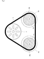
- Fig. 2 is a diagram of a cross section structure along the line AA' in Fig. 1 according to an embodiment of the present invention.
- Fig. 3 is a flow diagram illustrating a flow of a compressor lock detection control.
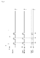
- Fig. 4 is a graph chart illustrating a sequence when determined that the compressor is locked according to an embodiment of the present invention.
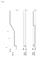
- Fig. 5 is a graph chart illustrating a sequence when determined that the compressor is normal according to an embodiment of the present invention.
- FIG. 1 A driving construction of a compressor 10 in an engine driven heat pump 1 will be briefly described, with reference to Fig. 1 .
- an engine 2 is connected to the compressor 10 via a belt 5.
- the engine 2 is disposed on an installation board 3 via an elastic member or the like aimed at vibration insulation and sound insulation, and is incorporated into a casing of the engine driven heat pump 1.
- the engine 2 includes a starter 6 for starting the engine.
- the engine 2 includes an engine pulley 4 on an output shaft.
- the compressor 10 includes a compressor pulley 11, an intake pipe 15 and a discharge pipe 16, and is incorporated into the casing of the engine driven heat pump 1 as with the engine 2.
- An input shaft 14 of the compressor 10 is rotatably driven by the driving transmission of the compressor pulley 11 via the belt 5 due to the engine pulley 4.
- the compressor 10 compresses an intake gas refrigerant at low temperature and low pressure inhaled from the intake pipe 15 into a discharge gas refrigerant at high temperature and high pressure, by rotating a scroll compression mechanism 13 due to the input shaft 14, and discharges the gas refrigerant from the discharge pipe 16.
- An electromagnetic clutch 20 is interposed between the input shaft 14 and the compressor pulley 11 as a clutch for the compressor.
- the electromagnetic clutch 20 includes a coil 17 provided integral with (attached and fixed to the inside of, in the present embodiment,) the compressor pulley 11 and an armature 12 engaged to one end of the input shaft 14 (that does not relatively rotate with respect to the input shaft 14 and that is slidable in the axial direction of the input shaft 14).
- An Electronic Control Unit (hereinafter, referred to as ECU 7) is connected to the respective systems and detection means (such as an ignition device, a temperature detection means and a rotation speed detection means 18) of the engine 2, the respective devices and detection means (an electronic expansion valve, an electromagnetic valve, a temperature detection means, a pressure detection means) of the engine drive heat pump 1 as well as the electromagnetic clutch 20, so as to control the operation of the engine drive heat pump 1.
- ECU 7 An Electronic Control Unit (hereinafter, referred to as ECU 7) is connected to the respective systems and detection means (such as an ignition device, a temperature detection means and a rotation speed detection means 18) of the engine 2, the respective devices and detection means (an electronic expansion valve, an electromagnetic valve, a temperature detection means, a pressure detection means) of the engine drive heat pump 1 as well as the electromagnetic clutch 20, so as to control the operation of the engine drive heat pump 1.
- the engine drive heat pump 1 of the present embodiment includes two compressors 10 of the first compressor 10a and the second compressor 10b.
- the belt 5 is provided and pulled so as to form as an approximately triangle with respect to the pulley 4 and the compressor pulleys 11a, 11b.
- the electromagnetic clutch 20 when the electromagnetic clutch 20 is disengaged, i.e., when the coil 17 is not excited, the armature 12 and the compressor pulley 11 are separated across a gap, and the compressor pulley 11 only ticks over. Briefly, the electromagnetic clutch 20 is disengaged, and the driving power of the engine 2 is not transmitted to the input shaft 14 of the compressor 10, so that the compressor 10 is stopped.
- the compressor lock means a state that the scroll compression mechanism 13 of the compression 10 is immovable, due to the liquid compression, rising of oil, or incorporation of foreign material.
- the slippage generating torque of the electromagnetic clutch 20 is set up to be the starting torque of the engine 2 (the starter) or higher. In other words, during the staring on the compression locked condition, the slippage is not generated in the electromagnetic clutch 20 and the engine 2 and the compressor 10 can not be rotated even when the electromagnetic clutch 20 is engaged, so that the engine 2 can not be started and the operation is locked.
- the ECU 7 starts the engine 2 (S, Step 110) by receiving ON command for starting the engine drive heat pump 1, or ON command for starting a thermostat when beyond the preset temperature after operating the heat pump (S, Step 100).
- the ECU 7 turns s o n two electromagnetic clutches of the electromagnetic clutches 20a, 20b regardless of size of the air-conditioning load.
- the ECU 7 stops the driving of the starter 6 by outputting an abnormal code E0, when the starter 6 is driven and the rotation speed of the input shaft 14 does not reach the preset rotation speed.
- Eo is an abnormal code when at least one compressor 10 is locked, or when the starter 6 cannot be started due to malfunction or the like.
- the ECU 7 evaluates that at least one compressor 10 is locked (or the starter is abnormal), when the engine 2 is continuously stopped at three times or more due to the Eo (S, Step 130) at the preset time t1. At this time, the ECU 7 evaluates that the operation gets stacked up and entirely stops the engine drive heat pump 1 (S, Step 210). The ECU 7 issues a warning by a warning device, so as to inform the operator of the abnormality.
- the starting clog means a state that the rotating speed of the engine or the compressor does not reach the predetermined rotating speed at the preset time t1, after starting the starting command by the ECU 7.
- Figs. 4 and 5 shows time series as the axis of abscissas, and shows the ON/OFF operation of the first compressor (Comp1), the ON/OFF operation of the second compressor (Comp2), and the engine rotation speed (Nrpm) of the engine (Engine) as axis of ordinate.
- the engine driven heat pump 1 is driven with the compressor 10b on the locked condition.
- the driving force is also transmitted to the compressor 10b on the locked condition so as to generate the starting clog, thereby stopping the engine driven heat pump 1. Consequently, it can be prevented that the engine driven heat pump 1 is driven by the compressor 10a, with the compressor 10b on the locked condition.
- the starting of the air conditioning operation can be avoided, if even one compressor is on the locked condition.
- the operation can be started from one of the compressor 10a (10b), by disengaging the electromagnetic clutch 20b (20a) after the starting of the engine 2 has finished.
- the capacity control for the compressor corresponding to the air conditioning load can be performed.
- the present invention is applicable in the engine driven heat pump.
Landscapes
- Engineering & Computer Science (AREA)
- Mechanical Engineering (AREA)
- General Engineering & Computer Science (AREA)
- Chemical & Material Sciences (AREA)
- Combustion & Propulsion (AREA)
- Physics & Mathematics (AREA)
- Thermal Sciences (AREA)
- Control Of Positive-Displacement Pumps (AREA)
- Control Of Vehicle Engines Or Engines For Specific Uses (AREA)
- Hydraulic Clutches, Magnetic Clutches, Fluid Clutches, And Fluid Joints (AREA)
- Air Conditioning Control Device (AREA)
- Compressors, Vaccum Pumps And Other Relevant Systems (AREA)
Abstract
An engine driven heat pump having a plurality of compressors, in which lock detection means can assuredly detect a lock of one compressor at the time of staring an air-conditioning operation. The engine driven heat pump (1) includes a plurality of compressors (10) via electromagnetic clutches (20). A slippage generating torque of the electromagnetic clutches (20) is set up to be a starting torque of an engine (2) or higher, and all of the electromagnetic clutches (20) are engaged at the time of starting the engine driven heat pump (1).
Description
- The present invention relates to an engine driven heat pump.
- Conventionally, there is well known an engine driven heat pump having a construction for driving a compressor by an engine. In the engine driven heat pump, the compressor is connected to the engine via a clutch. In other words, the compressor transmits or releases a driving power of the engine by an ON/OFF operation of the clutch.
- There is also well known a technology of a compressor lock detection means. Compressor lock means an abnormal state where compression mechanism of the compressor is not movable due to liquid compression, rising of oil or incorporation of foreign material. When the compressor lock is caused, it is necessary that all devices of the engine driven heat pump are stopped, so as to repair and replace the compressor. In other words, the compressor lock is the abnormal state (urgent abnormality) having a great need for maintenance and repair, unlike another abnormal states (such as engine accident fire).
-
JP1994-213171 JP 1994-213171
Briefly, in the engine driven heat pump, one compressor is continuously operated on condition that it remains locked. As a result, when engaging the clutch so as to transmit the driving power to the compressor on a locked condition, spark is sometimes generated due to clutch slippage. - In the engine driven heat pump having the plurality of compressors, the construction that transmits the driving power to one or plurality of compressors less than the volume on board at the starting has a possibility of being unable to assuredly avoid the starting of the air conditioning operation with the compressor on the locked condition, at the starting of the air conditioning operation.
- It's an object of the present invention to provide an engine driven heat pump having a plurality of compressors, capable of avoiding the starting of the air conditioning operation with the compressor on the locked condition.
- In an engine driven heat pump of the present invention, which is an engine driven heat pump having a plurality of compressors via clutches for the compressors, a slippage generating torque of the clutches for the compressors is set up to be starting torque of the engine or higher, and all of the clutches for the compressors are engaged, at the time of starting the engine driven heat pump.
- In the engine driven heat pump of the present invention, it is preferable to disengage at least one of the clutches for the compressors after finishing a starting of the engine.
- According to the engine driven heat pump of the present invention, in the engine driven heat pump having a plurality of compressors, it can be assuredly detected whether the compressor on the locked condition at the starting of the air conditioning operation is present or not. More specifically, although the construction that transmits the driving power to all of the compressors at the starting also transmits the driving power to the compressor on the locked condition, the operation is locked without causing the clutch slippage since the starting torque is the slippage generating torque of the clutch or lower, whereby the engine driven heat pump is not driven with the compressor on the locked condition. As the causes why the operation is locked are limited to (1) the compressor lock, (2) abnormality of a starter and so on, an operator can easily specify the compressor lock when it is generated.
- According to the engine driven heat pump of the present invention, driving for controlling compressor capacity corresponding to air-conditioning load can be performed, by disengaging at least one of the clutches for the compressors.
-
-
Fig. 1 is a diagram of a lateral construction illustrating driving construction of a compressor according to an embodiment of the present invention. -
Fig. 2 is a diagram of a cross section structure along the line AA' inFig. 1 according to an embodiment of the present invention. -
Fig. 3 is a flow diagram illustrating a flow of a compressor lock detection control. -
Fig. 4 is a graph chart illustrating a sequence when determined that the compressor is locked according to an embodiment of the present invention. -
Fig. 5 is a graph chart illustrating a sequence when determined that the compressor is normal according to an embodiment of the present invention. - Next, embodiments of the present invention will be described.
Fig. 1 is a diagram of a lateral construction illustrating driving construction of a compressor according to an embodiment of the present invention.Fig. 2 is a diagram of a cross section structure along the line AA' inFig. 1 according to an embodiment of the present invention.Fig. 3 is a flow diagram illustrating a flow of a compressor lock detection control.Fig. 4 is a graph chart illustrating a sequence when determined that the compressor is locked according to an embodiment of the present invention.Fig. 5 is a graph chart illustrating a sequence when determined that the compressor is normal according to an embodiment of the present invention. - A driving construction of a
compressor 10 in an engine drivenheat pump 1 will be briefly described, with reference toFig. 1 .
As shown inFig. 1 , anengine 2 is connected to thecompressor 10 via abelt 5.
Theengine 2 is disposed on aninstallation board 3 via an elastic member or the like aimed at vibration insulation and sound insulation, and is incorporated into a casing of the engine drivenheat pump 1. Theengine 2 includes astarter 6 for starting the engine. Theengine 2 includes anengine pulley 4 on an output shaft. - The
compressor 10 includes acompressor pulley 11, anintake pipe 15 and adischarge pipe 16, and is incorporated into the casing of the engine drivenheat pump 1 as with theengine 2. Aninput shaft 14 of thecompressor 10 is rotatably driven by the driving transmission of thecompressor pulley 11 via thebelt 5 due to theengine pulley 4. Thecompressor 10 compresses an intake gas refrigerant at low temperature and low pressure inhaled from theintake pipe 15 into a discharge gas refrigerant at high temperature and high pressure, by rotating ascroll compression mechanism 13 due to theinput shaft 14, and discharges the gas refrigerant from thedischarge pipe 16. - An
electromagnetic clutch 20 is interposed between theinput shaft 14 and thecompressor pulley 11 as a clutch for the compressor. Theelectromagnetic clutch 20 includes acoil 17 provided integral with (attached and fixed to the inside of, in the present embodiment,) thecompressor pulley 11 and anarmature 12 engaged to one end of the input shaft 14 (that does not relatively rotate with respect to theinput shaft 14 and that is slidable in the axial direction of the input shaft 14). - An Electronic Control Unit (hereinafter, referred to as ECU 7) is connected to the respective systems and detection means (such as an ignition device, a temperature detection means and a rotation speed detection means 18) of the
engine 2, the respective devices and detection means (an electronic expansion valve, an electromagnetic valve, a temperature detection means, a pressure detection means) of the enginedrive heat pump 1 as well as theelectromagnetic clutch 20, so as to control the operation of the enginedrive heat pump 1. - Moreover, the construction of the engine
drive heat pump 1 equipped with twocompressors 10 in oneengine 2 will be briefly described, with reference toFig. 2 .
As shown inFig, 2 , the enginedrive heat pump 1 of the present embodiment includes twocompressors 10 of thefirst compressor 10a and thesecond compressor 10b. Thebelt 5 is provided and pulled so as to form as an approximately triangle with respect to thepulley 4 and thecompressor pulleys - An ON/OFF action of the
electromagnetic clutch 20 for driving thecompressor 10 having the above construction will be described.
When theelectromagnetic clutch 20 is engaged, theECU 7 applies the current to thecoil 17 provided inside of thecompressor pulley 11 so as to excite it. Thearmature 12 slides and absorbs to the side of thecompressor pulley 11, due to flux generated in thecoil 17 of thecompressor pulley 11. Thearmature 12 and thecompressor pulley 11 become unified due to frictional engagement. Briefly, theelectromagnetic clutch 20 is engaged, and theinput shaft 14 of thecompressor 10 is rotatably driven, so as to put thecompressor 10 into operation.
Meanwhile, when theelectromagnetic clutch 20 is disengaged, i.e., when thecoil 17 is not excited, thearmature 12 and thecompressor pulley 11 are separated across a gap, and thecompressor pulley 11 only ticks over. Briefly, theelectromagnetic clutch 20 is disengaged, and the driving power of theengine 2 is not transmitted to theinput shaft 14 of thecompressor 10, so that thecompressor 10 is stopped. - The compressor lock, and the
electromagnetic clutch 20 on condition that the compressor is locked will be described.
The compressor lock means a state that thescroll compression mechanism 13 of thecompression 10 is immovable, due to the liquid compression, rising of oil, or incorporation of foreign material. When the driving power of thebelt 5 is transmitted to thecompressor pulley 11 and the starting torque is beyond the given torque (the slippage generating torque), thebelt 5 slides to thecompressor pulley 11. - In the present embodiment, the slippage generating torque of the
electromagnetic clutch 20 is set up to be the starting torque of the engine 2 (the starter) or higher. In other words, during the staring on the compression locked condition, the slippage is not generated in theelectromagnetic clutch 20 and theengine 2 and thecompressor 10 can not be rotated even when theelectromagnetic clutch 20 is engaged, so that theengine 2 can not be started and the operation is locked. - An avoidance control for the operation of the engine driven heat pump having the compressor on the locked condition according to the present invention will be described in detail, with reference to
Fig. 3 .
TheECU 7 starts the engine 2 (S, Step 110) by receiving ON command for starting the enginedrive heat pump 1, or ON command for starting a thermostat when beyond the preset temperature after operating the heat pump (S, Step 100).
TheECU 7 turns s o n two electromagnetic clutches of theelectromagnetic clutches ECU 7 stops the driving of thestarter 6 by outputting an abnormal code E0, when thestarter 6 is driven and the rotation speed of theinput shaft 14 does not reach the preset rotation speed. When theengine 2 is not continuously stopped at three times or more due to the Eo (S, Step 130) at the preset time t1, i.e., when theengine 2 is normally started, each one of theelectromagnetic clutches compression 10 is started (S, Step 150).
In this regard, Eo is an abnormal code when at least onecompressor 10 is locked, or when thestarter 6 cannot be started due to malfunction or the like. - Meanwhile, the
ECU 7 evaluates that at least onecompressor 10 is locked (or the starter is abnormal), when theengine 2 is continuously stopped at three times or more due to the Eo (S, Step 130) at the preset time t1. At this time, theECU 7 evaluates that the operation gets stacked up and entirely stops the engine drive heat pump 1 (S, Step 210). TheECU 7 issues a warning by a warning device, so as to inform the operator of the abnormality. In this regard, the starting clog means a state that the rotating speed of the engine or the compressor does not reach the predetermined rotating speed at the preset time t1, after starting the starting command by theECU 7. - Explanation will be given on each sequence of the
engine 2 and thecompressors Figs. 4 and5 .
Figs. 4 and5 shows time series as the axis of abscissas, and shows the ON/OFF operation of the first compressor (Comp1), the ON/OFF operation of the second compressor (Comp2), and the engine rotation speed (Nrpm) of the engine (Engine) as axis of ordinate. - Each of the sequences by the compressor lock detection control when the
second compressor 10b is locked (Rock) will be described in detail, with reference toFig. 4 .
As shown inFig. 4 , after theengine 2 receive s the starting command for the engine drivenheat pump 1, the engine 2 (the starter) cannot start and stops by the Eo, because thesecond compressor 10b is locked. Since the stop/restart by the E0 is continuously performed at three times during the preset time t1, the engine drivenheat pump 1 is totally stopped. - Thus, at the time of starting the air conditioning, it can be assuredly avoided that the engine driven
heat pump 1 is driven with thecompressor 10b on the locked condition. Specifically, due to the construction that the driving forces are transmitted to all of thecompressors compressor 10b on the locked condition so as to generate the starting clog, thereby stopping the engine drivenheat pump 1. Consequently, it can be prevented that the engine drivenheat pump 1 is driven by thecompressor 10a, with thecompressor 10b on the locked condition. In other words, in the engine drivenheat pump 1 equipped with twocompressors - Each of the sequences by the compressor lock detection control when both of the
first compressor 10a and thesecond compressor 10b are normal (Normal) will be described in detail, with reference toFig. 5 . As shown inFig. 5 , at this time, after theengine 2 receives the starting command for the engine drivenheat pump 1, the engine 2 (the starter 6) is normally started, as both of thefirst compressor 10a and thesecond compressor 10b are normal. After that, since one electromagnetic clutch 20b is disengaged, the engine drivenheat pump 1 is driven only by thefirst compressor 10a. The engine drivenheat pump 1 starts thesecond compressor 10b, corresponding to size of the air-conditioning load, and can be driven by two compressors. - Thus, the operation can be started from one of the
compressor 10a (10b), by disengaging the electromagnetic clutch 20b (20a) after the starting of theengine 2 has finished. Briefly, the capacity control for the compressor corresponding to the air conditioning load can be performed. - The present invention is applicable in the engine driven heat pump.
Claims (2)
- An engine driven heat pump having a plurality of compressors via clutches for the compressors,
wherein a slippage generating torque of the clutches for the compressors is set up to be a starting torque of the engine or higher, and
wherein all of the clutches for the compressors are engaged, at the time of starting the engine driven heat pump. - The engine driven heat pump as set forth in claim 1, wherein at least one of the clutches for the compressors are disengaged after finishing a starting of the engine.
Applications Claiming Priority (2)
| Application Number | Priority Date | Filing Date | Title |
|---|---|---|---|
| JP2007195217A JP2009030876A (en) | 2007-07-26 | 2007-07-26 | Engine-driven heat pump |
| PCT/JP2008/063390 WO2009014210A1 (en) | 2007-07-26 | 2008-07-25 | Engine-driven heat pump |
Publications (1)
| Publication Number | Publication Date |
|---|---|
| EP2184562A1 true EP2184562A1 (en) | 2010-05-12 |
Family
ID=40281457
Family Applications (1)
| Application Number | Title | Priority Date | Filing Date |
|---|---|---|---|
| EP08791634A Withdrawn EP2184562A1 (en) | 2007-07-26 | 2008-07-25 | Engine-driven heat pump |
Country Status (5)
| Country | Link |
|---|---|
| EP (1) | EP2184562A1 (en) |
| JP (1) | JP2009030876A (en) |
| KR (1) | KR20100038444A (en) |
| CN (1) | CN101772680A (en) |
| WO (1) | WO2009014210A1 (en) |
Families Citing this family (1)
| Publication number | Priority date | Publication date | Assignee | Title |
|---|---|---|---|---|
| KR102225856B1 (en) * | 2020-05-06 | 2021-03-09 | 서현석 | Gas engine driven heat pump system |
Family Cites Families (4)
| Publication number | Priority date | Publication date | Assignee | Title |
|---|---|---|---|---|
| JPH0413059A (en) * | 1990-04-28 | 1992-01-17 | Yamaha Motor Co Ltd | Operation system for heat pump type multi-system air conditioner |
| JPH06213171A (en) | 1992-11-25 | 1994-08-02 | Daikin Ind Ltd | Lock detecting device for compressor of inverter-driven air-conditioner |
| JP2000274455A (en) * | 1999-03-23 | 2000-10-03 | Toyota Autom Loom Works Ltd | Method for controlling electromagnetic clutch |
| JP2005351307A (en) * | 2004-06-08 | 2005-12-22 | Sanden Corp | Coupling unit of compressor |
-
2007
- 2007-07-26 JP JP2007195217A patent/JP2009030876A/en active Pending
-
2008
- 2008-07-25 KR KR1020107003025A patent/KR20100038444A/en not_active Ceased
- 2008-07-25 WO PCT/JP2008/063390 patent/WO2009014210A1/en not_active Ceased
- 2008-07-25 EP EP08791634A patent/EP2184562A1/en not_active Withdrawn
- 2008-07-25 CN CN200880100115A patent/CN101772680A/en active Pending
Non-Patent Citations (1)
| Title |
|---|
| See references of WO2009014210A1 * |
Also Published As
| Publication number | Publication date |
|---|---|
| WO2009014210A1 (en) | 2009-01-29 |
| KR20100038444A (en) | 2010-04-14 |
| CN101772680A (en) | 2010-07-07 |
| JP2009030876A (en) | 2009-02-12 |
Similar Documents
| Publication | Publication Date | Title |
|---|---|---|
| US8572956B2 (en) | Hydraulic pressure supply device of automatic transmission | |
| US9022748B2 (en) | Screw compressor | |
| EP2136079B1 (en) | Apparatus and method for controlling electric compressor | |
| KR101283044B1 (en) | Control method for vehicle drive source of hybrid vehicle in breakdown of transmission gear step | |
| JP2010281432A (en) | Hydraulic transmission device for automatic transmission | |
| CN103016170A (en) | Control apparatus for electric oil pump | |
| JP5012321B2 (en) | Hydraulic oil supply device for automatic transmission | |
| JP5416060B2 (en) | Control device for electric oil pump for vehicle | |
| JP4948204B2 (en) | Drive control device and drive control method for vehicle oil pump | |
| JP2010117072A (en) | Refrigerating device | |
| JP2013170529A (en) | Engine starter for idle stop vehicle | |
| CN106461077B (en) | For the abnormity determining device in vehicle hydraulic circuit | |
| CN105073538B (en) | The device for detecting fault and its failure judgment method of motor vehicle driven by mixed power | |
| JP5394569B2 (en) | Engine starter and control method for engine starter | |
| CN1536241A (en) | Electromagnetic clutch for a vehicle and a compressor for such a vehicle | |
| KR20090036509A (en) | How to operate the refrigeration unit and refrigeration unit | |
| JP2009030876A (en) | Engine-driven heat pump | |
| JP4075955B1 (en) | Diagnostic equipment | |
| JP2008180301A (en) | Hydraulic control device for automatic transmission for vehicle | |
| US11643952B2 (en) | Method of controlling electric oil pump for vehicle | |
| CN110778703A (en) | System and method for charging a transmission accumulator | |
| CN120990861A (en) | A controller control method for an integrated vehicle air compressor and power steering pump. | |
| JP4705845B2 (en) | Engine driven heat pump | |
| JP2006250436A (en) | Engine-driven heat pump | |
| JPH0519038B2 (en) |
Legal Events
| Date | Code | Title | Description |
|---|---|---|---|
| PUAI | Public reference made under article 153(3) epc to a published international application that has entered the european phase |
Free format text: ORIGINAL CODE: 0009012 |
|
| 17P | Request for examination filed |
Effective date: 20100226 |
|
| AK | Designated contracting states |
Kind code of ref document: A1 Designated state(s): AT BE BG CH CY CZ DE DK EE ES FI FR GB GR HR HU IE IS IT LI LT LU LV MC MT NL NO PL PT RO SE SI SK TR |
|
| AX | Request for extension of the european patent |
Extension state: AL BA MK RS |
|
| DAX | Request for extension of the european patent (deleted) | ||
| STAA | Information on the status of an ep patent application or granted ep patent |
Free format text: STATUS: THE APPLICATION IS DEEMED TO BE WITHDRAWN |
|
| 18D | Application deemed to be withdrawn |
Effective date: 20130201 |