EP2184495B1 - Method for limiting the maximum power required by the hydraulic system of an earth-moving machine and directional control valve operating said method - Google Patents
Method for limiting the maximum power required by the hydraulic system of an earth-moving machine and directional control valve operating said method Download PDFInfo
- Publication number
- EP2184495B1 EP2184495B1 EP20090174983 EP09174983A EP2184495B1 EP 2184495 B1 EP2184495 B1 EP 2184495B1 EP 20090174983 EP20090174983 EP 20090174983 EP 09174983 A EP09174983 A EP 09174983A EP 2184495 B1 EP2184495 B1 EP 2184495B1
- Authority
- EP
- European Patent Office
- Prior art keywords
- section
- passage
- flow
- compensator
- sections
- Prior art date
- Legal status (The legal status is an assumption and is not a legal conclusion. Google has not performed a legal analysis and makes no representation as to the accuracy of the status listed.)
- Not-in-force
Links
Images






Classifications
-
- F—MECHANICAL ENGINEERING; LIGHTING; HEATING; WEAPONS; BLASTING
- F15—FLUID-PRESSURE ACTUATORS; HYDRAULICS OR PNEUMATICS IN GENERAL
- F15B—SYSTEMS ACTING BY MEANS OF FLUIDS IN GENERAL; FLUID-PRESSURE ACTUATORS, e.g. SERVOMOTORS; DETAILS OF FLUID-PRESSURE SYSTEMS, NOT OTHERWISE PROVIDED FOR
- F15B11/00—Servomotor systems without provision for follow-up action; Circuits therefor
- F15B11/16—Servomotor systems without provision for follow-up action; Circuits therefor with two or more servomotors
- F15B11/161—Servomotor systems without provision for follow-up action; Circuits therefor with two or more servomotors with sensing of servomotor demand or load
- F15B11/163—Servomotor systems without provision for follow-up action; Circuits therefor with two or more servomotors with sensing of servomotor demand or load for sharing the pump output equally amongst users or groups of users, e.g. using anti-saturation, pressure compensation
-
- E—FIXED CONSTRUCTIONS
- E02—HYDRAULIC ENGINEERING; FOUNDATIONS; SOIL SHIFTING
- E02F—DREDGING; SOIL-SHIFTING
- E02F9/00—Component parts of dredgers or soil-shifting machines, not restricted to one of the kinds covered by groups E02F3/00 - E02F7/00
- E02F9/20—Drives; Control devices
- E02F9/22—Hydraulic or pneumatic drives
- E02F9/2221—Control of flow rate; Load sensing arrangements
- E02F9/2225—Control of flow rate; Load sensing arrangements using pressure-compensating valves
-
- F—MECHANICAL ENGINEERING; LIGHTING; HEATING; WEAPONS; BLASTING
- F15—FLUID-PRESSURE ACTUATORS; HYDRAULICS OR PNEUMATICS IN GENERAL
- F15B—SYSTEMS ACTING BY MEANS OF FLUIDS IN GENERAL; FLUID-PRESSURE ACTUATORS, e.g. SERVOMOTORS; DETAILS OF FLUID-PRESSURE SYSTEMS, NOT OTHERWISE PROVIDED FOR
- F15B11/00—Servomotor systems without provision for follow-up action; Circuits therefor
- F15B11/16—Servomotor systems without provision for follow-up action; Circuits therefor with two or more servomotors
- F15B11/161—Servomotor systems without provision for follow-up action; Circuits therefor with two or more servomotors with sensing of servomotor demand or load
- F15B11/162—Servomotor systems without provision for follow-up action; Circuits therefor with two or more servomotors with sensing of servomotor demand or load for giving priority to particular servomotors or users
-
- F—MECHANICAL ENGINEERING; LIGHTING; HEATING; WEAPONS; BLASTING
- F15—FLUID-PRESSURE ACTUATORS; HYDRAULICS OR PNEUMATICS IN GENERAL
- F15B—SYSTEMS ACTING BY MEANS OF FLUIDS IN GENERAL; FLUID-PRESSURE ACTUATORS, e.g. SERVOMOTORS; DETAILS OF FLUID-PRESSURE SYSTEMS, NOT OTHERWISE PROVIDED FOR
- F15B13/00—Details of servomotor systems ; Valves for servomotor systems
- F15B13/02—Fluid distribution or supply devices characterised by their adaptation to the control of servomotors
- F15B13/04—Fluid distribution or supply devices characterised by their adaptation to the control of servomotors for use with a single servomotor
- F15B13/0401—Valve members; Fluid interconnections therefor
- F15B13/0402—Valve members; Fluid interconnections therefor for linearly sliding valves, e.g. spool valves
-
- F—MECHANICAL ENGINEERING; LIGHTING; HEATING; WEAPONS; BLASTING
- F15—FLUID-PRESSURE ACTUATORS; HYDRAULICS OR PNEUMATICS IN GENERAL
- F15B—SYSTEMS ACTING BY MEANS OF FLUIDS IN GENERAL; FLUID-PRESSURE ACTUATORS, e.g. SERVOMOTORS; DETAILS OF FLUID-PRESSURE SYSTEMS, NOT OTHERWISE PROVIDED FOR
- F15B13/00—Details of servomotor systems ; Valves for servomotor systems
- F15B13/02—Fluid distribution or supply devices characterised by their adaptation to the control of servomotors
- F15B13/04—Fluid distribution or supply devices characterised by their adaptation to the control of servomotors for use with a single servomotor
- F15B13/0416—Fluid distribution or supply devices characterised by their adaptation to the control of servomotors for use with a single servomotor with means or adapted for load sensing
- F15B13/0417—Load sensing elements; Internal fluid connections therefor; Anti-saturation or pressure-compensation valves
-
- F—MECHANICAL ENGINEERING; LIGHTING; HEATING; WEAPONS; BLASTING
- F15—FLUID-PRESSURE ACTUATORS; HYDRAULICS OR PNEUMATICS IN GENERAL
- F15B—SYSTEMS ACTING BY MEANS OF FLUIDS IN GENERAL; FLUID-PRESSURE ACTUATORS, e.g. SERVOMOTORS; DETAILS OF FLUID-PRESSURE SYSTEMS, NOT OTHERWISE PROVIDED FOR
- F15B2211/00—Circuits for servomotor systems
- F15B2211/30—Directional control
- F15B2211/305—Directional control characterised by the type of valves
- F15B2211/30525—Directional control valves, e.g. 4/3-directional control valve
- F15B2211/3053—In combination with a pressure compensating valve
- F15B2211/30555—Inlet and outlet of the pressure compensating valve being connected to the directional control valve
Definitions
- the present finding is directed to the earth-moving machines field, in particular of the excavators controlled by a hydraulic system comprising at least one sectional flow-sharing directional control valve having multiple elements or sections (each element or section being provided with a spool and a compensator), at least one relief valve, at least one pump, and at least one motor capable of providing the power required.
- the present finding finds application in a well-specified and particular functioning configuration of the machine, i.e., that involving the complete and simultaneous actuation of at least one section of the directional control valve requiring all the flow that can be delivered by the pump and of at least another high pressure section.
- the current LS pumps (like the one of EP 1 610 002 ) are often provided with a torque limiter that is calibrated so that, if the required power, that is nothing else than the product of the flow and the pressure, exceeds that that required can be delivered by the motor, it intervenes by reducing the power.
- the torque limiter has to reduce at least one of the involved parameters (pressure and/or flow), and particular it intervenes on the flow by automatically reducing, as a function of the pressure, the maximum inclination possible of the pump plate and then the maximum flow.
- the required power falls back in the limits of the one that can be delivered by the motor, and the behaviour of the directional control valve, that continues to be consistent with the flow-sharing functional concepts, is at the maximum pressure (coincident to that of the relief valve added to the flow losses); and the maximum flow that is delivered continues to go to the travel sections, however, it being reduced because of the torque limiter intervention on the pump, the travel sections slow down.
- the present invention reduces the maximum pressure to a value such that, when multiplied by the maximum flow, the required power is always lower than that can be delivered by the motor, so that the section at the maximum flow (for example, the two travel sections previously mentioned) is not slowed down in case of the actuation of a third section at the end of the stroke of the cylinder.
- the pressure increase upon the actuation of a third high pressure section is generated, as better illustrated in the detailed descriptive part, by the local compensators of the sections that require the maximum flow (for example, the two travel sections), which throttle the passage (and so the flow) towards the travels because they are subjected to the Load Sensing signal coming from the actuated third member.
- the operations requiring high pressures would result to be thereby penalised, such as, for example, the excavating operation of the excavator; therefore, the optimum would be to reduce such maximum pressure only when the two travel sections are completely and concurrently actuate, to then make it to return to the relief valve value when the two travel sections are no more completely actuated.
- the present invention in the three implementation solutions thereof, looks for a functioning compromise, always in a flow-sharing logic, to achieve the best functionality of the machine.
- Said pressure limitation on the local compensators ends as the complete actuation of the sections, such as, for example, the travel sections, at the maximum flow stops, thus allowing the system to reach the calibration maximum pressure of the valve.
- the pressure limitation is also active in the case of an only partial requirement of flow and not only at the maximum flow requirement, with the consequence that partial negative effects could possibly occur, consisting in possible flow increases to the use compared to the desired one, that are anyway compensated by a considerable constructive simplification of the directional control valve, as described below.
- the system illustrated in Fig. 1 comprises a sectional flow-sharing directional control valve having 3 sections (A, B, and C), a relief valve D, a load sensing pump PP, and a motor M; each of the sections A, B, or C of the system flow-sharing valve comprises a spool 2 and a compensator 1.
- the two A and B sections of the valve control the excavator travels that is, the actuation of the feeding means, and that the third section C controls a cylinder;
- the sections A and B are conventionally sized so that, when the two travels are completely and concurrently actuated, they require the maximum flow Q that can be delivered by the pump PP, and in particular each of the sections A and B requires half of the maximum flow Q, i.e., Q/2.
- the pressure increase is not due to the signal LS increase to the pump PP, but to the fact that this signal arrives to the local compensators 1 of the sections A and B.
- the local compensators 1 of the sections A and B then intervene, according to the known flow-sharing logic, throttling the flow to the travels, and in doing so, it is they that increase the delivery pressure until arriving to the end situation, in which all the flow continues to go to the travels, which therefore do not slow down, but with a delivery pressure that is equal to the relief valve D calibration pressure plus the pump PP limit, according to the flows and pressures distribution highlighted in the simplified diagram of Fig. 10 .
- the relief valve is calibrated at 250 bars, therefore there are, in the sections A and B, 270 bars from the pump PP to the spools 2 (delivery pressure), 250 bars downstream the spools 2, and 250 bars in the LS line.
- first motors M (generally endothermic) capable of meeting the requirement of maximum power P max that there is in the case of the requirement of the maximum flow Q max at the maximum pressure p max , that is the relief valve D calibration one, it results that the motor M would turn off.
- the present finding solves the above-mentioned slowdown/acceleration problem of the machine translation by intervening on the other power factor, i.e., on the pressure p; such result is obtained by bypassing the local compensators of the section(s) that require the maximum flow (for example, of the travel sections) in the instant in which it/they is/are completely and concurrently actuated relative to a third section with cylinder at the end of its stroke; said bypassing occurs by imparting a delivery pressure lower than that imparted by the relief valve D calibration.
- the present finding can be applied both to hydraulic systems in which the LS pump is provided with a torque limiter, and to systems in which the pump is not provided with it.
- the avobe-mentioned delivery pressure is calculated so that the power required is:
- the local compensators intervention should have to be calibrated so that they create a delivery pressure not higher than 180 bars.
- a first method for limiting the maximum pressure in the case of completely actuated travels A and B together with a third section C is to make so that the spools 2 of the sections A and B, at the end of their stroke, open a passage 3 between the two areas upstream 4 and downstream 5 the compensator 1 thereof, so as to bypass the same.
- Said passage 3 is a recess that is obtained on the spool 2 of section A, B, as illustrated in detail in Fig. 2A .
- Said passage 3 has to be such that, at the delivery pressure of 180 bars calculated before, all the maximum flow Q (Q/2 per travel) passes through it, and not through the compensator 1, that is practically shut out.
- the flows and pressures distribution is as follows: 180 bars from the pump PP to the spools 2 (delivery pressure), 160 bars downstream the spools 2, and 180 bars in the LS line.
- a second method for limiting the maximum pressure consists in opening a passage 2E, practically, a hole, between the two areas upstream 4 and downstream 5 the compensator 1 directly in the section A and B.
- Said passage 2E is calculated so that, at the delivery pressure of 180 bars calculated before, all the flow Q (Q/2 per travel) passes through it, thus bypassing the compensator 1.
- the flows and pressures distribution is as follows: 180 bars from the pump PP to the spools 2 (delivery pressure), 160 bars downstream the spools 2, and 180 bars in the LS line.
- the pressure limiting is, however, active also in the case of only partial requirement of the flow, and not only at the maximum requirement, with the consequence that, when the travels sections A, B are partially actuated, flow increases to the use compared to that desired can occur, which translate in acceleration phenomena.
- a third method for limiting the maximum pressure consists in using a compensator 1A that is designed so that, at the end of the stroke, it leaves a passage 2G open, through which all the flow Q passes (Q/2 per travel) at the previously calculated pressure of 180 bars.
- Said passage 2G is obtained by limiting the compensator stroke so as not to let it completely close, or through a recess obtained on the same compensator.
- the limitation of the maximum pressure is active also in the case of only partial requirement of flow, and not only at the maximum requirement, therefore in intermediate positions of the spool 2 of the travels A and B, acceleration phenomena can occur; however, such disadvantages are compensated by the simplicity of the solution.
Landscapes
- Engineering & Computer Science (AREA)
- Physics & Mathematics (AREA)
- Fluid Mechanics (AREA)
- General Engineering & Computer Science (AREA)
- Mechanical Engineering (AREA)
- Mining & Mineral Resources (AREA)
- Civil Engineering (AREA)
- Structural Engineering (AREA)
- Fluid-Pressure Circuits (AREA)
- Operation Control Of Excavators (AREA)
Description
- The present finding is directed to the earth-moving machines field, in particular of the excavators controlled by a hydraulic system comprising at least one sectional flow-sharing directional control valve having multiple elements or sections (each element or section being provided with a spool and a compensator), at least one relief valve, at least one pump, and at least one motor capable of providing the power required.
- More precisely, the present finding finds application in a well-specified and particular functioning configuration of the machine, i.e., that involving the complete and simultaneous actuation of at least one section of the directional control valve requiring all the flow that can be delivered by the pump and of at least another high pressure section.
- An example of that is the case where two sections of the sectional directional control valve, termed "travel" in the jargon, control the excavator translation while the third one controls a cylinder: when both said travel sections, which usually require together the maximum flow, are completely and concurrently actuated, and the third section is in turn actuated, for example, at the relief valve calibration with the cylinder at the end of its stroke, the required may come to exceed the one that can be delivered by the motor, which consequently turns off.
- In order to avoid exceeding the power that can be delivered by the motor, the current LS pumps (like the one of
EP 1 610 002 - To reduce the required power, the torque limiter has to reduce at least one of the involved parameters (pressure and/or flow), and particular it intervenes on the flow by automatically reducing, as a function of the pressure, the maximum inclination possible of the pump plate and then the maximum flow.
- In so doing, the required power falls back in the limits of the one that can be delivered by the motor, and the behaviour of the directional control valve, that continues to be consistent with the flow-sharing functional concepts, is at the maximum pressure (coincident to that of the relief valve added to the flow losses); and the maximum flow that is delivered continues to go to the travel sections, however, it being reduced because of the torque limiter intervention on the pump, the travel sections slow down.
- The result is that upon actuating a third high pressure element, the machine translation slows down, to then accelerate again when it is released.
- This machine behaviour, even not being a malfunctioning, but the logical consequence of the system functioning, is not desired by the operator; besides, however, it is neither acceptable that the system requires a power higher than the one that can be delivered by the motor.
- It is the object of the present discovery to obviate the above-cited drawbacks, i.e., the slowdown and acceleration of the machine translation following the actuation of a further section to that or those already completely actuated and requiring the maximum flow that can be delivered, by reducing the power required from the motor intervening on the pressure instead of on the flow, as is typical of the prior art.
- The present invention reduces the maximum pressure to a value such that, when multiplied by the maximum flow, the required power is always lower than that can be delivered by the motor, so that the section at the maximum flow (for example, the two travel sections previously mentioned) is not slowed down in case of the actuation of a third section at the end of the stroke of the cylinder.
- The pressure increase upon the actuation of a third high pressure section is generated, as better illustrated in the detailed descriptive part, by the local compensators of the sections that require the maximum flow (for example, the two travel sections), which throttle the passage (and so the flow) towards the travels because they are subjected to the Load Sensing signal coming from the actuated third member.
- By bypassing the local compensators of such sections, the pressure would not increase, the torque limiter would not intervene, and therefore the travel sections would continue to work at the maximum speed also during the actuation of a further section at the end of the stroke; however, in this manner, the travel sections would not act as flow-sharing with the other ones anymore.
- Instead, by reducing the maximum pressure in each functioning condition of the machine, the operations requiring high pressures would result to be thereby penalised, such as, for example, the excavating operation of the excavator; therefore, the optimum would be to reduce such maximum pressure only when the two travel sections are completely and concurrently actuate, to then make it to return to the relief valve value when the two travel sections are no more completely actuated. The present invention, in the three implementation solutions thereof, looks for a functioning compromise, always in a flow-sharing logic, to achieve the best functionality of the machine.
- According to a first functioning logic of the finding, which finds application in the first implementation solution, it is made sure that the compensators "inhibition" only occurs with the section(s) at the maximum flow being actuated at the end of their stroke, while the compensator works properly in intermediate positions.
- Therefore, if the maximum pressure that can be delivered by the local compensators of the sections at the maximum flow (it is reminded that the system is of the flow-sharing type, with LS functioning) is calculated so that the product of the flow and the pressure does not make the torque limiter to intervene, then upon actuating the third section as indicated above, the pump flow does not decrease, therefore the section will have the whole maximum flow of the pump, thus avoiding the problem described above.
- Said pressure limitation on the local compensators ends as the complete actuation of the sections, such as, for example, the travel sections, at the maximum flow stops, thus allowing the system to reach the calibration maximum pressure of the valve.
- According to a further functioning logic of the finding, that finds application in the second and third implementation solutions, the pressure limitation is also active in the case of an only partial requirement of flow and not only at the maximum flow requirement, with the consequence that partial negative effects could possibly occur, consisting in possible flow increases to the use compared to the desired one, that are anyway compensated by a considerable constructive simplification of the directional control valve, as described below.
- Said objects and advantages are all achieved by the method for limiting the maximum power required by the hydraulic system of an earth-moving machine and by the directional control valve operating said method, which is the object of the present finding, characterized in what has been provided for in the claims reported below.
- This and other characteristics will result more highlighted by the following description of some embodiments illustrated, by way of non-limiting example, in the annexed drawings.
-
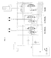
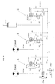
Fig. 1 : partial diagram of a mini excavator system comprising a sectional flow-sharing directional control valve, a pump, motors, a cylinder, and a relief valve, which is typical of the prior art; -
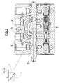
Fig. 2 : section of an element of the flow-sharing directional control valve with the maximum pressure limiting system that is the object of the present finding (first implementation solution); -
Fig. 2A : an enlargement of the recess obtained on the spool 2 (first implementation solution); -
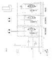
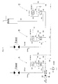
Fig. 3 : hydraulic diagram of a mini excavator system comprising the flow-sharing directional control valve with the maximum pressure limiting system that is the object of the present finding (first implementation solution); -
Fig. 4 : section of an element of the flow-sharing directional control valve with the maximum pressure limiting system that is the object of the present finding (second implementation solution); -
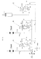
Fig. 5 : hydraulic diagram of a mini excavator system comprising the flow-sharing directional control valve with the maximum pressure limiting system that is the object of the present finding (second implementation solution); -
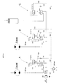
Fig. 6 : section of an element of the flow-sharing directional control valve with the maximum pressure limiting system that is the object of the present finding (third implementation solution); -
Fig. 7 : hydraulic diagram of a mini excavator system comprising the flow-sharing directional control valve with the maximum pressure limiting system that is the object of the present finding (third implementation solution); -
Fig. 8 : hydraulic diagram with distribution of the flows and pressures of the flow-sharing directional control valve that is typical of the prior art, with the 2 travel sections completely and concurrently actuated; -
Fig. 9 : hydraulic diagram with distribution of the flows and pressures of the flow-sharing directional control valve that is typical of the prior art, upon actuating the third section with cylinder at the end of the stroke; -
Fig. 10 : hydraulic diagram with distribution of the flows and pressures of the flow-sharing directional control valve that is typical of the prior art, under conditions of complete flow that is sent to the travels and delivery pressure equal to the relief valve calibration pressure plus the pump limit; -
Fig. 11 : hydraulic diagram with distribution of the flows and pressures of the system with the flow-sharing directional control valve with the maximum pressure limiting system that is the object of the present finding (first implementation solution); -
Fig. 12 : hydraulic diagram with distribution the flows and pressures of the system with the flow-sharing directional control valve with the maximum pressure limiting system that is the object of the present finding (second implementation solution); -
Fig. 13 : hydraulic diagram with distribution the flows and pressures of the system with the flow-sharing directional control valve with the maximum pressure limiting system that is the object of the present finding (third implementation solution). - With particular reference to
Figs. 1 ,8 , and9 , the functioning characteristics of an excavator system with the maximum power limiting system that is typical of the prior art and the problems related thereto are illustrated. - The system illustrated in
Fig. 1 comprises a sectional flow-sharing directional control valve having 3 sections (A, B, and C), a relief valve D, a load sensing pump PP, and a motor M; each of the sections A, B, or C of the system flow-sharing valve comprises aspool 2 and acompensator 1. - It is assumed that the two A and B sections of the valve control the excavator travels, that is, the actuation of the feeding means, and that the third section C controls a cylinder; the sections A and B are conventionally sized so that, when the two travels are completely and concurrently actuated, they require the maximum flow Q that can be delivered by the pump PP, and in particular each of the sections A and B requires half of the maximum flow Q, i.e., Q/2.
- This means that, by completely actuating the two travel sections A and B, the pump plate PP is inclined at most, thus providing the maximum flow Qmax possible; in such situation, the flows and pressures distribution is represented in the simplified diagram of
Fig. 8 . - The above-reported hypothesis, in its widest meaning, also provides for the actuation of a single section, A or B, completely actuated so as to require all the maximum flow Q that can be delivered by the pump PP.
- Referring again to the example reported above, it is assumed that for the actuation of the travels, which are controlled by the sections A and B, 100 bars are needed, that the pump PP limit is of 20 bars, and that the flow losses through the fully open
local compensator 1 are null (because the sections A and B are those at the highest pressure); therefore, there are 100 bars downstream thespools - When also a third section C is actuated, concurrently to the sections A and B, and that the cylinder controlled by it is at the end of its stroke, a transient is present, in which the new flows and pressures distribution is reported in the simplified diagram of
Fig. 9 . - Since the cylinder controlled by the section C is at the end of its stroke, the same pressure as the delivery - 120 bars - arrives to the signal LS, therefore to the pump PP, without anyway generating alterations to the state of the pump PP itself, as it is already at its maximum.
- Therefore, in this situation of maximum flow, the pressure increase is not due to the signal LS increase to the pump PP, but to the fact that this signal arrives to the
local compensators 1 of the sections A and B. - The
local compensators 1 of the sections A and B then intervene, according to the known flow-sharing logic, throttling the flow to the travels, and in doing so, it is they that increase the delivery pressure until arriving to the end situation, in which all the flow continues to go to the travels, which therefore do not slow down, but with a delivery pressure that is equal to the relief valve D calibration pressure plus the pump PP limit, according to the flows and pressures distribution highlighted in the simplified diagram ofFig. 10 . - Assumed that the relief valve is calibrated at 250 bars, therefore there are, in the sections A and B, 270 bars from the pump PP to the spools 2 (delivery pressure), 250 bars downstream the
spools - This behaviour will then continue to be controlled according to the flow-sharing logic.
- Since the machines are usually not equipped with first motors M (generally endothermic) capable of meeting the requirement of maximum power Pmax that there is in the case of the requirement of the maximum flow Qmax at the maximum pressure pmax, that is the relief valve D calibration one, it results that the motor M would turn off.
- To obviate this problem, the prior art usually uses LS pumps provided with a torque limiter that is calibrated so that, if the required power P = Q x p exceeds the one that is generable by the motor M, it intervenes by reducing the required power, i.e., by reducing at least one of the two involved parameters; in particular, the pump torque limiter intervenes on the flow Q by automatically reducing, as a function of the pressure, the maximum inclination possible of the pump plate, therefore the maximum flow Qmax.
- The result, as previously described, is that upon actuating a third element C at high pressure, the machine translation slows down, to then accelerate again when it is released.
- The present finding solves the above-mentioned slowdown/acceleration problem of the machine translation by intervening on the other power factor, i.e., on the pressure p; such result is obtained by bypassing the local compensators of the section(s) that require the maximum flow (for example, of the travel sections) in the instant in which it/they is/are completely and concurrently actuated relative to a third section with cylinder at the end of its stroke; said bypassing occurs by imparting a delivery pressure lower than that imparted by the relief valve D calibration.
- The present finding can be applied both to hydraulic systems in which the LS pump is provided with a torque limiter, and to systems in which the pump is not provided with it.
- The avobe-mentioned delivery pressure is calculated so that the power required is:
- Less than or equal to the power that can be delivered by the motor M, if the system pump PP is not provided with a torque limiter;
- or, alternatively,
- less than the power at which the torque limiter is tripped, if the system pump PP is provided with a torque limiter.
- Assuming that, at the maximum flow, the torque limiter operates upon reaching 190 bars, the local compensators intervention should have to be calibrated so that they create a delivery pressure not higher than 180 bars.
- In this manner, upon actuating the third section C, the pump PP flow does not decrease, therefore the travels do not slow down (i.e., the sections at the maximum flow continue to operate in such configuration), thus avoiding the previously described problem.
- Three possible embodiments of the invention in order to limit the maximum pressure are described herein below.
- With particular reference to
Figs. 2 ,3 , and11 the first constructive solution of the maximum pressure limiting system that is the object of the present finding is described. - A first method for limiting the maximum pressure in the case of completely actuated travels A and B together with a third section C is to make so that the
spools 2 of the sections A and B, at the end of their stroke, open apassage 3 between the two areas upstream 4 and downstream 5 thecompensator 1 thereof, so as to bypass the same. - Said
passage 3 is a recess that is obtained on thespool 2 of section A, B, as illustrated in detail inFig. 2A . - Said
passage 3 has to be such that, at the delivery pressure of 180 bars calculated before, all the maximum flow Q (Q/2 per travel) passes through it, and not through thecompensator 1, that is practically shut out. By doing so, when thespools 2 of the travels A and B are completely actuated, and a third section C is actuated, the maximum flow Q (which, in the example, is divided in Q/2 per part) continues to go entirely to the travels A and B, the delivery pressure does not reach the calibration pressure value of the relief valve D, but only the set pressure value (the above-mentioned 180 bars). - At this pressure value, the torque limiter is tripped, therefore the travels do not slow down, thus obviating the problem reported above.
- As illustrated in the simplified diagram of
Fig. 11 , the flows and pressures distribution is as follows: 180 bars from the pump PP to the spools 2 (delivery pressure), 160 bars downstream thespools - With particular reference to
Figs. 4 ,5 , and12 , the second constructive solution of the maximum pressure limiting system that is the object of the present finding is illustrated. - A second method for limiting the maximum pressure consists in opening a
passage 2E, practically, a hole, between the two areas upstream 4 and downstream 5 thecompensator 1 directly in the section A and B. - Said
passage 2E is calculated so that, at the delivery pressure of 180 bars calculated before, all the flow Q (Q/2 per travel) passes through it, thus bypassing thecompensator 1. - As illustrated in the simplified diagram of
Fig. 12 , the flows and pressures distribution is as follows: 180 bars from the pump PP to the spools 2 (delivery pressure), 160 bars downstream thespools - With the through
hole 2E obtained directly in the sections A and B, the pressure limiting is, however, active also in the case of only partial requirement of the flow, and not only at the maximum requirement, with the consequence that, when the travels sections A, B are partially actuated, flow increases to the use compared to that desired can occur, which translate in acceleration phenomena. - However, on the other hand, the solution cost is lower, it being constructively easier.
- With particular reference to
Figs. 6 ,7 , and13 , the third constructive solution of the maximum pressure limiting system that is the object of the present finding is illustrated. - A third method for limiting the maximum pressure consists in using a compensator 1A that is designed so that, at the end of the stroke, it leaves a
passage 2G open, through which all the flow Q passes (Q/2 per travel) at the previously calculated pressure of 180 bars. - Said
passage 2G is obtained by limiting the compensator stroke so as not to let it completely close, or through a recess obtained on the same compensator. - Also in this case, as in the second constructive solution, the limitation of the maximum pressure is active also in the case of only partial requirement of flow, and not only at the maximum requirement, therefore in intermediate positions of the
spool 2 of the travels A and B, acceleration phenomena can occur; however, such disadvantages are compensated by the simplicity of the solution. - This functionality is always valid when the power required P, given by the maximum flow absorbed by the travels for the maximum pressure delivered by a third use C with the cylinder at the end of its stroke, exceeds the maximum power that can be delivered by the motor M, independently from the presence or not of the torque limiter.
- The optional absence of the torque limiter does not rise the motor turning off problem, since this is avoided by limiting the maximum pressure as described before.
- The same applies also if the pump PP is not LS, and a compensator is then comprised on the flow-sharing directional control valve side.
Claims (8)
- A method for limiting the maximum power required by the hydraulic system of an earth-moving machine, such hydraulic system being composed of a sectional flow-sharing directional control valve having multiple sections (A, B, C), each section comprising a local compensator (1) and a spool (2), with one section (A) or (B) or both the sections (A) and (B) requiring the maximum flow and at least one additional section (C) designed for actuating a work function of the machine, a pump (PP) with or without torque limiter, a motor (M) and a relief valve (D), characterized in that it includes the step of bypassing the local compensators (1) of the section and/or sections (A, B) requiring the maximum flow when they are fully actuated at the same time as the third section (C), to impart a lower delivery pressure than that of the relief valve (D), and calculated so that the power required is:• less than or equal to the power that can be delivered by the motor (M), if the pump (PP) has no torque limiter or• less than the power at which the torque limiter is tripped, if the pump (PP) has one whereby the flow is not reduced.
- The method as claimed in claim 1, characterized in that it includes the step of bypassing the local compensator (1) of the section and/or sections (A, B) requiring the maximum flow, by opening a passage (3) between the two areas upstream (4) and downstream (5) from the compensator (1); said passage (3) being directly opened by the spool/s (2) of the section/s (A, B) at the end of their stroke ; said passage (3) being calculated so that, with the delivery pressure appropriately calculated as claimed in claim 1, all the maximum flow passes through it and not through the compensator (1).
- The method as claimed in claim 1, characterized in that it includes the step of bypassing the local compensator (1) of the section and/or sections (A, B) 10 requiring the maximum flow, by opening a passage (2E) between the two areas upstream (4) and downstream (5) from the local compensator (1), directly machined into the sections (A, B) requiring the maximum flow; said passage (2E) being calculated so that, with the delivery pressure appropriately calculated as claimed in claim 1, all the maximum flow passes through it and bypasses the compensator (1).
- The method as claimed in claim 1, characterized in that it includes the step of bypassing the local compensator (1) of the section and/or sections (A, B) requiring the maximum flow, by opening a passage (2G) that is left open by the local compensator (1) itself at the end of its stroke, said passage (2G) being calculated so that, with the delivery pressure appropriately calculated as claimed in claim 1, all the flow passes through it and bypasses the compensator (1).
- A sectional flow-sharing directional control valve having multiple sections (A, B, C), each section comprising a local compensator (1) and a spool (2), a pump (PP) with or without a torque limiter, a motor (M) and a relief valve (D), characterized in that the section/s (A, B) designed to operate at the maximum flow open a passage (3, 2E, 2G) to bypass the local compensator (1) if a third section (C) is actuated; said passage (3, 2E, 2G) being calculated so that, with the delivery pressure appropriately calculated as claimed in claim 1, all the flow passes through such passage (3, 2E, 2G).
- The directional control valve as claimed in claim 5, characterized in that said passage (3) is directly opened by a recess formed on the spool (2) at the end of its stroke, between the two areas upstream (4) and downstream (5) from the local compensator (1).
- The directional control valve as claimed in claim 5, characterized in that said passage (2E) is a hole formed between the two areas upstream (4) and downstream (5) from the local compensator (1), directly machined in the section/s (A, B) requiring the maximum flow.
- The directional control valve as claimed in claim 5, characterized in that said passage (2G) is opened directly by the local compensator (1) itself at the end of its stroke.
Applications Claiming Priority (1)
| Application Number | Priority Date | Filing Date | Title |
|---|---|---|---|
| ITPR2008A000071A IT1391608B1 (en) | 2008-11-06 | 2008-11-06 | METHOD TO LIMIT THE MAXIMUM POWER REQUIRED FROM THE HYDRAULIC SYSTEM OF AN EARTH-MOVING MACHINE AND OPERATING DISTRIBUTOR OF THE METHOD |
Publications (2)
| Publication Number | Publication Date |
|---|---|
| EP2184495A1 EP2184495A1 (en) | 2010-05-12 |
| EP2184495B1 true EP2184495B1 (en) | 2014-01-08 |
Family
ID=41076717
Family Applications (1)
| Application Number | Title | Priority Date | Filing Date |
|---|---|---|---|
| EP20090174983 Not-in-force EP2184495B1 (en) | 2008-11-06 | 2009-11-04 | Method for limiting the maximum power required by the hydraulic system of an earth-moving machine and directional control valve operating said method |
Country Status (2)
| Country | Link |
|---|---|
| EP (1) | EP2184495B1 (en) |
| IT (1) | IT1391608B1 (en) |
Families Citing this family (6)
| Publication number | Priority date | Publication date | Assignee | Title |
|---|---|---|---|---|
| US8756930B2 (en) * | 2010-05-28 | 2014-06-24 | Caterpillar Inc. | Hydraulic system having implement and steering flow sharing |
| ITPR20110039A1 (en) | 2011-05-13 | 2012-11-14 | Walvoil Spa | HYDRAULIC DISTRIBUTOR WITH PARALLEL CONNECTION TO THE CURSOR FLOW RATE ADJUSTMENT AND LOCAL COMPENSATOR |
| KR102167422B1 (en) * | 2013-01-31 | 2020-10-20 | 파커-한니핀 코포레이션 | Pressure limited flow priority boost |
| US9464580B2 (en) | 2014-01-02 | 2016-10-11 | Caterpillar Paving Products Inc. | Torque limit control |
| WO2018137014A1 (en) * | 2017-01-27 | 2018-08-02 | Caramona Empreendimentos E Participações Ltda | Hydraulic or pneumatic system |
| CN116292524B (en) * | 2023-03-13 | 2025-08-29 | 中国铁建重工集团股份有限公司 | Power flow control method and system for hydraulic system of cantilever roadheader |
Family Cites Families (4)
| Publication number | Priority date | Publication date | Assignee | Title |
|---|---|---|---|---|
| JP4128482B2 (en) * | 2002-04-30 | 2008-07-30 | 東芝機械株式会社 | Hydraulic control system |
| JP2004019873A (en) * | 2002-06-19 | 2004-01-22 | Toyota Industries Corp | Hydraulic control device and industrial vehicle with the hydraulic control device |
| ATE391238T1 (en) * | 2004-06-24 | 2008-04-15 | Walvoil Spa | MULTIPLE SECTION LOAD SENSING HYDRAULIC SYSTEM |
| ITPR20060036A1 (en) * | 2006-04-12 | 2007-10-13 | Walvoil Spa | PRESSURE COMPENSATOR WITH DIFFERENTIAL AREAS PILOTED AND ITS PILOT SYSTEM. |
-
2008
- 2008-11-06 IT ITPR2008A000071A patent/IT1391608B1/en active
-
2009
- 2009-11-04 EP EP20090174983 patent/EP2184495B1/en not_active Not-in-force
Also Published As
| Publication number | Publication date |
|---|---|
| EP2184495A1 (en) | 2010-05-12 |
| ITPR20080071A1 (en) | 2010-05-07 |
| IT1391608B1 (en) | 2012-01-11 |
Similar Documents
| Publication | Publication Date | Title |
|---|---|---|
| EP2184495A1 (en) | Method for limiting the maximum power required by the hydraulic system of an earth-moving machine and directional control valve operating said method | |
| US9091281B2 (en) | System for allocating fluid from multiple pumps to a plurality of hydraulic functions on a priority basis | |
| KR100996322B1 (en) | Hydraulic control device | |
| KR102156446B1 (en) | Hydraulic system of Construction machinery | |
| US9650232B2 (en) | Hydraulic drive apparatus for work machine | |
| US11231053B2 (en) | Hydraulic valve arrangement | |
| WO2013171801A1 (en) | Oil-pressure control system | |
| EP1143151B1 (en) | Pipe breakage control valve device | |
| US10196246B2 (en) | Hydraulic control circuit for crane slewing gear | |
| JPWO1989008200A1 (en) | Hydraulic drive method and hydraulic drive device for hydraulic machine | |
| EP2951442B1 (en) | Directional control valve with bypass for increased flow rate under reduced pressure conditions | |
| KR100527378B1 (en) | hydraulic circuit of option device of heavy equipment of having spool boom joint | |
| EP2518224B1 (en) | Pump control system for a construction machine | |
| US6405529B1 (en) | Hydraulic system for utility vehicles | |
| JP2006283784A (en) | Hydraulic circuit | |
| EP2580483B1 (en) | Hydraulic system and hydraulic distributor for actuating working machines | |
| EP0684387B1 (en) | Load-sensing active hydraulic control device | |
| JP3481675B2 (en) | Hydraulic circuit of construction machinery | |
| JP3535759B2 (en) | Hydraulic valve control device | |
| JP2019015334A (en) | Hydraulic device | |
| JP3499601B2 (en) | Hydraulic circuit of construction machinery | |
| US20030121258A1 (en) | Hydraulic control system for reducing motor cavitation | |
| EP3390843B1 (en) | Modular directional valve with two or more elements of mixed type | |
| WO2026004615A1 (en) | Fluid pressure circuit | |
| JP2003287002A (en) | Hydraulic circuit in working machinery |
Legal Events
| Date | Code | Title | Description |
|---|---|---|---|
| PUAI | Public reference made under article 153(3) epc to a published international application that has entered the european phase |
Free format text: ORIGINAL CODE: 0009012 |
|
| AK | Designated contracting states |
Kind code of ref document: A1 Designated state(s): AT BE BG CH CY CZ DE DK EE ES FI FR GB GR HR HU IE IS IT LI LT LU LV MC MK MT NL NO PL PT RO SE SI SK SM TR |
|
| AX | Request for extension of the european patent |
Extension state: AL BA RS |
|
| 17P | Request for examination filed |
Effective date: 20101112 |
|
| RIC1 | Information provided on ipc code assigned before grant |
Ipc: F15B 11/16 20060101AFI20110131BHEP |
|
| GRAP | Despatch of communication of intention to grant a patent |
Free format text: ORIGINAL CODE: EPIDOSNIGR1 |
|
| INTG | Intention to grant announced |
Effective date: 20130606 |
|
| GRAS | Grant fee paid |
Free format text: ORIGINAL CODE: EPIDOSNIGR3 |
|
| GRAA | (expected) grant |
Free format text: ORIGINAL CODE: 0009210 |
|
| AK | Designated contracting states |
Kind code of ref document: B1 Designated state(s): AT BE BG CH CY CZ DE DK EE ES FI FR GB GR HR HU IE IS IT LI LT LU LV MC MK MT NL NO PL PT RO SE SI SK SM TR |
|
| REG | Reference to a national code |
Ref country code: GB Ref legal event code: FG4D |
|
| REG | Reference to a national code |
Ref country code: CH Ref legal event code: EP |
|
| REG | Reference to a national code |
Ref country code: IE Ref legal event code: FG4D |
|
| REG | Reference to a national code |
Ref country code: AT Ref legal event code: REF Ref document number: 648929 Country of ref document: AT Kind code of ref document: T Effective date: 20140215 |
|
| REG | Reference to a national code |
Ref country code: DE Ref legal event code: R096 Ref document number: 602009021248 Country of ref document: DE Effective date: 20140220 |
|
| REG | Reference to a national code |
Ref country code: AT Ref legal event code: MK05 Ref document number: 648929 Country of ref document: AT Kind code of ref document: T Effective date: 20140108 |
|
| REG | Reference to a national code |
Ref country code: NL Ref legal event code: VDEP Effective date: 20140108 |
|
| REG | Reference to a national code |
Ref country code: LT Ref legal event code: MG4D |
|
| PG25 | Lapsed in a contracting state [announced via postgrant information from national office to epo] |
Ref country code: LT Free format text: LAPSE BECAUSE OF FAILURE TO SUBMIT A TRANSLATION OF THE DESCRIPTION OR TO PAY THE FEE WITHIN THE PRESCRIBED TIME-LIMIT Effective date: 20140108 Ref country code: NO Free format text: LAPSE BECAUSE OF FAILURE TO SUBMIT A TRANSLATION OF THE DESCRIPTION OR TO PAY THE FEE WITHIN THE PRESCRIBED TIME-LIMIT Effective date: 20140408 Ref country code: IS Free format text: LAPSE BECAUSE OF FAILURE TO SUBMIT A TRANSLATION OF THE DESCRIPTION OR TO PAY THE FEE WITHIN THE PRESCRIBED TIME-LIMIT Effective date: 20140508 |
|
| PG25 | Lapsed in a contracting state [announced via postgrant information from national office to epo] |
Ref country code: FI Free format text: LAPSE BECAUSE OF FAILURE TO SUBMIT A TRANSLATION OF THE DESCRIPTION OR TO PAY THE FEE WITHIN THE PRESCRIBED TIME-LIMIT Effective date: 20140108 Ref country code: NL Free format text: LAPSE BECAUSE OF FAILURE TO SUBMIT A TRANSLATION OF THE DESCRIPTION OR TO PAY THE FEE WITHIN THE PRESCRIBED TIME-LIMIT Effective date: 20140108 Ref country code: PT Free format text: LAPSE BECAUSE OF FAILURE TO SUBMIT A TRANSLATION OF THE DESCRIPTION OR TO PAY THE FEE WITHIN THE PRESCRIBED TIME-LIMIT Effective date: 20140508 Ref country code: CY Free format text: LAPSE BECAUSE OF FAILURE TO SUBMIT A TRANSLATION OF THE DESCRIPTION OR TO PAY THE FEE WITHIN THE PRESCRIBED TIME-LIMIT Effective date: 20140108 Ref country code: AT Free format text: LAPSE BECAUSE OF FAILURE TO SUBMIT A TRANSLATION OF THE DESCRIPTION OR TO PAY THE FEE WITHIN THE PRESCRIBED TIME-LIMIT Effective date: 20140108 Ref country code: ES Free format text: LAPSE BECAUSE OF FAILURE TO SUBMIT A TRANSLATION OF THE DESCRIPTION OR TO PAY THE FEE WITHIN THE PRESCRIBED TIME-LIMIT Effective date: 20140108 Ref country code: SE Free format text: LAPSE BECAUSE OF FAILURE TO SUBMIT A TRANSLATION OF THE DESCRIPTION OR TO PAY THE FEE WITHIN THE PRESCRIBED TIME-LIMIT Effective date: 20140108 |
|
| PG25 | Lapsed in a contracting state [announced via postgrant information from national office to epo] |
Ref country code: LV Free format text: LAPSE BECAUSE OF FAILURE TO SUBMIT A TRANSLATION OF THE DESCRIPTION OR TO PAY THE FEE WITHIN THE PRESCRIBED TIME-LIMIT Effective date: 20140108 Ref country code: HR Free format text: LAPSE BECAUSE OF FAILURE TO SUBMIT A TRANSLATION OF THE DESCRIPTION OR TO PAY THE FEE WITHIN THE PRESCRIBED TIME-LIMIT Effective date: 20140108 Ref country code: BE Free format text: LAPSE BECAUSE OF FAILURE TO SUBMIT A TRANSLATION OF THE DESCRIPTION OR TO PAY THE FEE WITHIN THE PRESCRIBED TIME-LIMIT Effective date: 20140108 |
|
| REG | Reference to a national code |
Ref country code: DE Ref legal event code: R097 Ref document number: 602009021248 Country of ref document: DE |
|
| PG25 | Lapsed in a contracting state [announced via postgrant information from national office to epo] |
Ref country code: EE Free format text: LAPSE BECAUSE OF FAILURE TO SUBMIT A TRANSLATION OF THE DESCRIPTION OR TO PAY THE FEE WITHIN THE PRESCRIBED TIME-LIMIT Effective date: 20140108 Ref country code: RO Free format text: LAPSE BECAUSE OF FAILURE TO SUBMIT A TRANSLATION OF THE DESCRIPTION OR TO PAY THE FEE WITHIN THE PRESCRIBED TIME-LIMIT Effective date: 20140108 Ref country code: DK Free format text: LAPSE BECAUSE OF FAILURE TO SUBMIT A TRANSLATION OF THE DESCRIPTION OR TO PAY THE FEE WITHIN THE PRESCRIBED TIME-LIMIT Effective date: 20140108 Ref country code: CZ Free format text: LAPSE BECAUSE OF FAILURE TO SUBMIT A TRANSLATION OF THE DESCRIPTION OR TO PAY THE FEE WITHIN THE PRESCRIBED TIME-LIMIT Effective date: 20140108 |
|
| PLBE | No opposition filed within time limit |
Free format text: ORIGINAL CODE: 0009261 |
|
| STAA | Information on the status of an ep patent application or granted ep patent |
Free format text: STATUS: NO OPPOSITION FILED WITHIN TIME LIMIT |
|
| PG25 | Lapsed in a contracting state [announced via postgrant information from national office to epo] |
Ref country code: PL Free format text: LAPSE BECAUSE OF FAILURE TO SUBMIT A TRANSLATION OF THE DESCRIPTION OR TO PAY THE FEE WITHIN THE PRESCRIBED TIME-LIMIT Effective date: 20140108 Ref country code: SK Free format text: LAPSE BECAUSE OF FAILURE TO SUBMIT A TRANSLATION OF THE DESCRIPTION OR TO PAY THE FEE WITHIN THE PRESCRIBED TIME-LIMIT Effective date: 20140108 |
|
| 26N | No opposition filed |
Effective date: 20141009 |
|
| REG | Reference to a national code |
Ref country code: DE Ref legal event code: R097 Ref document number: 602009021248 Country of ref document: DE Effective date: 20141009 |
|
| PG25 | Lapsed in a contracting state [announced via postgrant information from national office to epo] |
Ref country code: SI Free format text: LAPSE BECAUSE OF FAILURE TO SUBMIT A TRANSLATION OF THE DESCRIPTION OR TO PAY THE FEE WITHIN THE PRESCRIBED TIME-LIMIT Effective date: 20140108 |
|
| PG25 | Lapsed in a contracting state [announced via postgrant information from national office to epo] |
Ref country code: MC Free format text: LAPSE BECAUSE OF FAILURE TO SUBMIT A TRANSLATION OF THE DESCRIPTION OR TO PAY THE FEE WITHIN THE PRESCRIBED TIME-LIMIT Effective date: 20140108 Ref country code: LU Free format text: LAPSE BECAUSE OF FAILURE TO SUBMIT A TRANSLATION OF THE DESCRIPTION OR TO PAY THE FEE WITHIN THE PRESCRIBED TIME-LIMIT Effective date: 20141104 |
|
| REG | Reference to a national code |
Ref country code: CH Ref legal event code: PL |
|
| GBPC | Gb: european patent ceased through non-payment of renewal fee |
Effective date: 20141104 |
|
| PG25 | Lapsed in a contracting state [announced via postgrant information from national office to epo] |
Ref country code: LI Free format text: LAPSE BECAUSE OF NON-PAYMENT OF DUE FEES Effective date: 20141130 Ref country code: CH Free format text: LAPSE BECAUSE OF NON-PAYMENT OF DUE FEES Effective date: 20141130 |
|
| REG | Reference to a national code |
Ref country code: IE Ref legal event code: MM4A |
|
| PG25 | Lapsed in a contracting state [announced via postgrant information from national office to epo] |
Ref country code: IE Free format text: LAPSE BECAUSE OF NON-PAYMENT OF DUE FEES Effective date: 20141104 Ref country code: GB Free format text: LAPSE BECAUSE OF NON-PAYMENT OF DUE FEES Effective date: 20141104 |
|
| REG | Reference to a national code |
Ref country code: FR Ref legal event code: PLFP Year of fee payment: 7 |
|
| PG25 | Lapsed in a contracting state [announced via postgrant information from national office to epo] |
Ref country code: SM Free format text: LAPSE BECAUSE OF FAILURE TO SUBMIT A TRANSLATION OF THE DESCRIPTION OR TO PAY THE FEE WITHIN THE PRESCRIBED TIME-LIMIT Effective date: 20140108 |
|
| PG25 | Lapsed in a contracting state [announced via postgrant information from national office to epo] |
Ref country code: BG Free format text: LAPSE BECAUSE OF FAILURE TO SUBMIT A TRANSLATION OF THE DESCRIPTION OR TO PAY THE FEE WITHIN THE PRESCRIBED TIME-LIMIT Effective date: 20140108 Ref country code: GR Free format text: LAPSE BECAUSE OF FAILURE TO SUBMIT A TRANSLATION OF THE DESCRIPTION OR TO PAY THE FEE WITHIN THE PRESCRIBED TIME-LIMIT Effective date: 20140409 |
|
| PG25 | Lapsed in a contracting state [announced via postgrant information from national office to epo] |
Ref country code: MT Free format text: LAPSE BECAUSE OF FAILURE TO SUBMIT A TRANSLATION OF THE DESCRIPTION OR TO PAY THE FEE WITHIN THE PRESCRIBED TIME-LIMIT Effective date: 20140108 Ref country code: HU Free format text: LAPSE BECAUSE OF FAILURE TO SUBMIT A TRANSLATION OF THE DESCRIPTION OR TO PAY THE FEE WITHIN THE PRESCRIBED TIME-LIMIT; INVALID AB INITIO Effective date: 20091104 Ref country code: TR Free format text: LAPSE BECAUSE OF FAILURE TO SUBMIT A TRANSLATION OF THE DESCRIPTION OR TO PAY THE FEE WITHIN THE PRESCRIBED TIME-LIMIT Effective date: 20140108 |
|
| REG | Reference to a national code |
Ref country code: FR Ref legal event code: PLFP Year of fee payment: 8 |
|
| REG | Reference to a national code |
Ref country code: FR Ref legal event code: PLFP Year of fee payment: 9 |
|
| PG25 | Lapsed in a contracting state [announced via postgrant information from national office to epo] |
Ref country code: MK Free format text: LAPSE BECAUSE OF FAILURE TO SUBMIT A TRANSLATION OF THE DESCRIPTION OR TO PAY THE FEE WITHIN THE PRESCRIBED TIME-LIMIT Effective date: 20140108 |
|
| P01 | Opt-out of the competence of the unified patent court (upc) registered |
Effective date: 20230622 |
|
| PGFP | Annual fee paid to national office [announced via postgrant information from national office to epo] |
Ref country code: IT Payment date: 20231129 Year of fee payment: 15 Ref country code: FR Payment date: 20231120 Year of fee payment: 15 Ref country code: DE Payment date: 20231121 Year of fee payment: 15 |
|
| REG | Reference to a national code |
Ref country code: DE Ref legal event code: R119 Ref document number: 602009021248 Country of ref document: DE |
|
| PG25 | Lapsed in a contracting state [announced via postgrant information from national office to epo] |
Ref country code: DE Free format text: LAPSE BECAUSE OF NON-PAYMENT OF DUE FEES Effective date: 20250603 |
|
| PG25 | Lapsed in a contracting state [announced via postgrant information from national office to epo] |
Ref country code: IT Free format text: LAPSE BECAUSE OF NON-PAYMENT OF DUE FEES Effective date: 20241104 |
|
| PG25 | Lapsed in a contracting state [announced via postgrant information from national office to epo] |
Ref country code: FR Free format text: LAPSE BECAUSE OF NON-PAYMENT OF DUE FEES Effective date: 20241130 |