EP2184320B1 - Fire-resistant piping material - Google Patents
Fire-resistant piping material Download PDFInfo
- Publication number
- EP2184320B1 EP2184320B1 EP07806242.9A EP07806242A EP2184320B1 EP 2184320 B1 EP2184320 B1 EP 2184320B1 EP 07806242 A EP07806242 A EP 07806242A EP 2184320 B1 EP2184320 B1 EP 2184320B1
- Authority
- EP
- European Patent Office
- Prior art keywords
- fire
- pipe
- resistant
- heat
- expandable
- Prior art date
- Legal status (The legal status is an assumption and is not a legal conclusion. Google has not performed a legal analysis and makes no representation as to the accuracy of the status listed.)
- Active
Links
Images


Classifications
-
- C—CHEMISTRY; METALLURGY
- C08—ORGANIC MACROMOLECULAR COMPOUNDS; THEIR PREPARATION OR CHEMICAL WORKING-UP; COMPOSITIONS BASED THEREON
- C08L—COMPOSITIONS OF MACROMOLECULAR COMPOUNDS
- C08L27/00—Compositions of homopolymers or copolymers of compounds having one or more unsaturated aliphatic radicals, each having only one carbon-to-carbon double bond, and at least one being terminated by a halogen; Compositions of derivatives of such polymers
- C08L27/02—Compositions of homopolymers or copolymers of compounds having one or more unsaturated aliphatic radicals, each having only one carbon-to-carbon double bond, and at least one being terminated by a halogen; Compositions of derivatives of such polymers not modified by chemical after-treatment
- C08L27/04—Compositions of homopolymers or copolymers of compounds having one or more unsaturated aliphatic radicals, each having only one carbon-to-carbon double bond, and at least one being terminated by a halogen; Compositions of derivatives of such polymers not modified by chemical after-treatment containing chlorine atoms
- C08L27/06—Homopolymers or copolymers of vinyl chloride
-
- B—PERFORMING OPERATIONS; TRANSPORTING
- B32—LAYERED PRODUCTS
- B32B—LAYERED PRODUCTS, i.e. PRODUCTS BUILT-UP OF STRATA OF FLAT OR NON-FLAT, e.g. CELLULAR OR HONEYCOMB, FORM
- B32B1/00—Layered products having a non-planar shape
- B32B1/08—Tubular products
-
- B—PERFORMING OPERATIONS; TRANSPORTING
- B32—LAYERED PRODUCTS
- B32B—LAYERED PRODUCTS, i.e. PRODUCTS BUILT-UP OF STRATA OF FLAT OR NON-FLAT, e.g. CELLULAR OR HONEYCOMB, FORM
- B32B13/00—Layered products comprising a a layer of water-setting substance, e.g. concrete, plaster, asbestos cement, or like builders' material
- B32B13/04—Layered products comprising a a layer of water-setting substance, e.g. concrete, plaster, asbestos cement, or like builders' material comprising such water setting substance as the main or only constituent of a layer, which is next to another layer of the same or of a different material
- B32B13/12—Layered products comprising a a layer of water-setting substance, e.g. concrete, plaster, asbestos cement, or like builders' material comprising such water setting substance as the main or only constituent of a layer, which is next to another layer of the same or of a different material of synthetic resin
-
- B—PERFORMING OPERATIONS; TRANSPORTING
- B32—LAYERED PRODUCTS
- B32B—LAYERED PRODUCTS, i.e. PRODUCTS BUILT-UP OF STRATA OF FLAT OR NON-FLAT, e.g. CELLULAR OR HONEYCOMB, FORM
- B32B21/00—Layered products comprising a layer of wood, e.g. wood board, veneer, wood particle board
- B32B21/04—Layered products comprising a layer of wood, e.g. wood board, veneer, wood particle board comprising wood as the main or only constituent of a layer, which is next to another layer of the same or of a different material
- B32B21/08—Layered products comprising a layer of wood, e.g. wood board, veneer, wood particle board comprising wood as the main or only constituent of a layer, which is next to another layer of the same or of a different material of synthetic resin
-
- B—PERFORMING OPERATIONS; TRANSPORTING
- B32—LAYERED PRODUCTS
- B32B—LAYERED PRODUCTS, i.e. PRODUCTS BUILT-UP OF STRATA OF FLAT OR NON-FLAT, e.g. CELLULAR OR HONEYCOMB, FORM
- B32B27/00—Layered products comprising a layer of synthetic resin
- B32B27/18—Layered products comprising a layer of synthetic resin characterised by the use of special additives
-
- B—PERFORMING OPERATIONS; TRANSPORTING
- B32—LAYERED PRODUCTS
- B32B—LAYERED PRODUCTS, i.e. PRODUCTS BUILT-UP OF STRATA OF FLAT OR NON-FLAT, e.g. CELLULAR OR HONEYCOMB, FORM
- B32B27/00—Layered products comprising a layer of synthetic resin
- B32B27/30—Layered products comprising a layer of synthetic resin comprising vinyl (co)polymers; comprising acrylic (co)polymers
-
- B—PERFORMING OPERATIONS; TRANSPORTING
- B32—LAYERED PRODUCTS
- B32B—LAYERED PRODUCTS, i.e. PRODUCTS BUILT-UP OF STRATA OF FLAT OR NON-FLAT, e.g. CELLULAR OR HONEYCOMB, FORM
- B32B27/00—Layered products comprising a layer of synthetic resin
- B32B27/32—Layered products comprising a layer of synthetic resin comprising polyolefins
-
- B—PERFORMING OPERATIONS; TRANSPORTING
- B32—LAYERED PRODUCTS
- B32B—LAYERED PRODUCTS, i.e. PRODUCTS BUILT-UP OF STRATA OF FLAT OR NON-FLAT, e.g. CELLULAR OR HONEYCOMB, FORM
- B32B27/00—Layered products comprising a layer of synthetic resin
- B32B27/32—Layered products comprising a layer of synthetic resin comprising polyolefins
- B32B27/322—Layered products comprising a layer of synthetic resin comprising polyolefins comprising halogenated polyolefins, e.g. PTFE
-
- B—PERFORMING OPERATIONS; TRANSPORTING
- B32—LAYERED PRODUCTS
- B32B—LAYERED PRODUCTS, i.e. PRODUCTS BUILT-UP OF STRATA OF FLAT OR NON-FLAT, e.g. CELLULAR OR HONEYCOMB, FORM
- B32B27/00—Layered products comprising a layer of synthetic resin
- B32B27/40—Layered products comprising a layer of synthetic resin comprising polyurethanes
-
- C—CHEMISTRY; METALLURGY
- C08—ORGANIC MACROMOLECULAR COMPOUNDS; THEIR PREPARATION OR CHEMICAL WORKING-UP; COMPOSITIONS BASED THEREON
- C08K—Use of inorganic or non-macromolecular organic substances as compounding ingredients
- C08K3/00—Use of inorganic substances as compounding ingredients
- C08K3/02—Elements
- C08K3/04—Carbon
-
- F—MECHANICAL ENGINEERING; LIGHTING; HEATING; WEAPONS; BLASTING
- F16—ENGINEERING ELEMENTS AND UNITS; GENERAL MEASURES FOR PRODUCING AND MAINTAINING EFFECTIVE FUNCTIONING OF MACHINES OR INSTALLATIONS; THERMAL INSULATION IN GENERAL
- F16L—PIPES; JOINTS OR FITTINGS FOR PIPES; SUPPORTS FOR PIPES, CABLES OR PROTECTIVE TUBING; MEANS FOR THERMAL INSULATION IN GENERAL
- F16L5/00—Devices for use where pipes, cables or protective tubing pass through walls or partitions
- F16L5/02—Sealing
- F16L5/04—Sealing to form a firebreak device
-
- F—MECHANICAL ENGINEERING; LIGHTING; HEATING; WEAPONS; BLASTING
- F16—ENGINEERING ELEMENTS AND UNITS; GENERAL MEASURES FOR PRODUCING AND MAINTAINING EFFECTIVE FUNCTIONING OF MACHINES OR INSTALLATIONS; THERMAL INSULATION IN GENERAL
- F16L—PIPES; JOINTS OR FITTINGS FOR PIPES; SUPPORTS FOR PIPES, CABLES OR PROTECTIVE TUBING; MEANS FOR THERMAL INSULATION IN GENERAL
- F16L55/00—Devices or appurtenances for use in, or in connection with, pipes or pipe systems
- F16L55/10—Means for stopping flow in pipes or hoses
- F16L55/1026—Fire protection devices
-
- F—MECHANICAL ENGINEERING; LIGHTING; HEATING; WEAPONS; BLASTING
- F16—ENGINEERING ELEMENTS AND UNITS; GENERAL MEASURES FOR PRODUCING AND MAINTAINING EFFECTIVE FUNCTIONING OF MACHINES OR INSTALLATIONS; THERMAL INSULATION IN GENERAL
- F16L—PIPES; JOINTS OR FITTINGS FOR PIPES; SUPPORTS FOR PIPES, CABLES OR PROTECTIVE TUBING; MEANS FOR THERMAL INSULATION IN GENERAL
- F16L59/00—Thermal insulation in general
- F16L59/14—Arrangements for the insulation of pipes or pipe systems
- F16L59/145—Arrangements for the insulation of pipes or pipe systems providing fire-resistance
-
- F—MECHANICAL ENGINEERING; LIGHTING; HEATING; WEAPONS; BLASTING
- F16—ENGINEERING ELEMENTS AND UNITS; GENERAL MEASURES FOR PRODUCING AND MAINTAINING EFFECTIVE FUNCTIONING OF MACHINES OR INSTALLATIONS; THERMAL INSULATION IN GENERAL
- F16L—PIPES; JOINTS OR FITTINGS FOR PIPES; SUPPORTS FOR PIPES, CABLES OR PROTECTIVE TUBING; MEANS FOR THERMAL INSULATION IN GENERAL
- F16L9/00—Rigid pipes
- F16L9/12—Rigid pipes of plastics with or without reinforcement
- F16L9/121—Rigid pipes of plastics with or without reinforcement with three layers
-
- B—PERFORMING OPERATIONS; TRANSPORTING
- B32—LAYERED PRODUCTS
- B32B—LAYERED PRODUCTS, i.e. PRODUCTS BUILT-UP OF STRATA OF FLAT OR NON-FLAT, e.g. CELLULAR OR HONEYCOMB, FORM
- B32B2270/00—Resin or rubber layer containing a blend of at least two different polymers
-
- B—PERFORMING OPERATIONS; TRANSPORTING
- B32—LAYERED PRODUCTS
- B32B—LAYERED PRODUCTS, i.e. PRODUCTS BUILT-UP OF STRATA OF FLAT OR NON-FLAT, e.g. CELLULAR OR HONEYCOMB, FORM
- B32B2274/00—Thermoplastic elastomer material
-
- B—PERFORMING OPERATIONS; TRANSPORTING
- B32—LAYERED PRODUCTS
- B32B—LAYERED PRODUCTS, i.e. PRODUCTS BUILT-UP OF STRATA OF FLAT OR NON-FLAT, e.g. CELLULAR OR HONEYCOMB, FORM
- B32B2307/00—Properties of the layers or laminate
- B32B2307/30—Properties of the layers or laminate having particular thermal properties
- B32B2307/306—Resistant to heat
- B32B2307/3065—Flame resistant or retardant, fire resistant or retardant
-
- B—PERFORMING OPERATIONS; TRANSPORTING
- B32—LAYERED PRODUCTS
- B32B—LAYERED PRODUCTS, i.e. PRODUCTS BUILT-UP OF STRATA OF FLAT OR NON-FLAT, e.g. CELLULAR OR HONEYCOMB, FORM
- B32B2307/00—Properties of the layers or laminate
- B32B2307/30—Properties of the layers or laminate having particular thermal properties
- B32B2307/308—Heat stability
-
- B—PERFORMING OPERATIONS; TRANSPORTING
- B32—LAYERED PRODUCTS
- B32B—LAYERED PRODUCTS, i.e. PRODUCTS BUILT-UP OF STRATA OF FLAT OR NON-FLAT, e.g. CELLULAR OR HONEYCOMB, FORM
- B32B2307/00—Properties of the layers or laminate
- B32B2307/70—Other properties
- B32B2307/718—Weight, e.g. weight per square meter
-
- B—PERFORMING OPERATIONS; TRANSPORTING
- B32—LAYERED PRODUCTS
- B32B—LAYERED PRODUCTS, i.e. PRODUCTS BUILT-UP OF STRATA OF FLAT OR NON-FLAT, e.g. CELLULAR OR HONEYCOMB, FORM
- B32B2597/00—Tubular articles, e.g. hoses, pipes
-
- Y—GENERAL TAGGING OF NEW TECHNOLOGICAL DEVELOPMENTS; GENERAL TAGGING OF CROSS-SECTIONAL TECHNOLOGIES SPANNING OVER SEVERAL SECTIONS OF THE IPC; TECHNICAL SUBJECTS COVERED BY FORMER USPC CROSS-REFERENCE ART COLLECTIONS [XRACs] AND DIGESTS
- Y10—TECHNICAL SUBJECTS COVERED BY FORMER USPC
- Y10T—TECHNICAL SUBJECTS COVERED BY FORMER US CLASSIFICATION
- Y10T428/00—Stock material or miscellaneous articles
- Y10T428/13—Hollow or container type article [e.g., tube, vase, etc.]
- Y10T428/1352—Polymer or resin containing [i.e., natural or synthetic]
-
- Y—GENERAL TAGGING OF NEW TECHNOLOGICAL DEVELOPMENTS; GENERAL TAGGING OF CROSS-SECTIONAL TECHNOLOGIES SPANNING OVER SEVERAL SECTIONS OF THE IPC; TECHNICAL SUBJECTS COVERED BY FORMER USPC CROSS-REFERENCE ART COLLECTIONS [XRACs] AND DIGESTS
- Y10—TECHNICAL SUBJECTS COVERED BY FORMER USPC
- Y10T—TECHNICAL SUBJECTS COVERED BY FORMER US CLASSIFICATION
- Y10T428/00—Stock material or miscellaneous articles
- Y10T428/13—Hollow or container type article [e.g., tube, vase, etc.]
- Y10T428/1352—Polymer or resin containing [i.e., natural or synthetic]
- Y10T428/1355—Elemental metal containing [e.g., substrate, foil, film, coating, etc.]
- Y10T428/1359—Three or more layers [continuous layer]
-
- Y—GENERAL TAGGING OF NEW TECHNOLOGICAL DEVELOPMENTS; GENERAL TAGGING OF CROSS-SECTIONAL TECHNOLOGIES SPANNING OVER SEVERAL SECTIONS OF THE IPC; TECHNICAL SUBJECTS COVERED BY FORMER USPC CROSS-REFERENCE ART COLLECTIONS [XRACs] AND DIGESTS
- Y10—TECHNICAL SUBJECTS COVERED BY FORMER USPC
- Y10T—TECHNICAL SUBJECTS COVERED BY FORMER US CLASSIFICATION
- Y10T428/00—Stock material or miscellaneous articles
- Y10T428/13—Hollow or container type article [e.g., tube, vase, etc.]
- Y10T428/1352—Polymer or resin containing [i.e., natural or synthetic]
- Y10T428/1379—Contains vapor or gas barrier, polymer derived from vinyl chloride or vinylidene chloride, or polymer containing a vinyl alcohol unit
-
- Y—GENERAL TAGGING OF NEW TECHNOLOGICAL DEVELOPMENTS; GENERAL TAGGING OF CROSS-SECTIONAL TECHNOLOGIES SPANNING OVER SEVERAL SECTIONS OF THE IPC; TECHNICAL SUBJECTS COVERED BY FORMER USPC CROSS-REFERENCE ART COLLECTIONS [XRACs] AND DIGESTS
- Y10—TECHNICAL SUBJECTS COVERED BY FORMER USPC
- Y10T—TECHNICAL SUBJECTS COVERED BY FORMER US CLASSIFICATION
- Y10T428/00—Stock material or miscellaneous articles
- Y10T428/13—Hollow or container type article [e.g., tube, vase, etc.]
- Y10T428/1352—Polymer or resin containing [i.e., natural or synthetic]
- Y10T428/139—Open-ended, self-supporting conduit, cylinder, or tube-type article
-
- Y—GENERAL TAGGING OF NEW TECHNOLOGICAL DEVELOPMENTS; GENERAL TAGGING OF CROSS-SECTIONAL TECHNOLOGIES SPANNING OVER SEVERAL SECTIONS OF THE IPC; TECHNICAL SUBJECTS COVERED BY FORMER USPC CROSS-REFERENCE ART COLLECTIONS [XRACs] AND DIGESTS
- Y10—TECHNICAL SUBJECTS COVERED BY FORMER USPC
- Y10T—TECHNICAL SUBJECTS COVERED BY FORMER US CLASSIFICATION
- Y10T428/00—Stock material or miscellaneous articles
- Y10T428/13—Hollow or container type article [e.g., tube, vase, etc.]
- Y10T428/1352—Polymer or resin containing [i.e., natural or synthetic]
- Y10T428/139—Open-ended, self-supporting conduit, cylinder, or tube-type article
- Y10T428/1393—Multilayer [continuous layer]
Definitions
- the present invention particularly relates to a fire-resistant pipe that is excellent in fire resistance and is used in a construction passing through a partition of a building.
- Buildings have fireproof compartments defined depending on the types and specifications of the buildings.
- flooring materials and wall materials for fireproof construction or semi-fireproof construction prescribed by the Building Standards Act are used.
- the flooring materials and the wall materials for fireproof construction or semi-fireproof construction prescribed by the Building Standards Act are those defined by the Minister of Land, Infrastructure, Transport and Tourism or certified by the Minister of Land, Infrastructure, Transport and Tourism, and examples thereof include ferroconcrete; concrete blocks, brick constructions, and stone constructions that are reinforced with iron materials; iron materials covered with steel mortar or concrete on both surfaces thereof; lightweight foamed concrete; precast concrete plates; and laminates of plywood and gypsum board, hard wood chip cement board, or lightweight foamed concrete.
- buildings are provided with piping (such as electrical conduits, drain pipes, and ducts).
- piping such as electrical conduits, drain pipes, and ducts.
- Such piping passes through the above-mentioned fireproof compartment in some cases.
- compartment pass-through portion When a through-hole through which piping or the like passes (hereinafter, referred to as "compartment pass-through portion") is provided to the above-mentioned fireproof compartment, occurrence of fire may cause a big fire accident within a short period of time by that the fire and smoke quickly penetrate from the room where the fire occurred to the next room having the fireproof compartment therebetween through the compartment pass-through portion.
- the Building Standards Act establishes that only materials that passed a fire-resistant test for compartment pass-through and certified by the Minister of Land, Infrastructure, Transport and Tourism or evaluated by fire defense can be used as the pipe passing through the compartment pass-through portion in a building.
- the compartment pass-through portion is provided with fire-protection measures for caulking a gap with a noncombustible material such as mortar after installing the piping passing through the compartment so that no gap is formed between the compartment pass-through portion and the piping.
- the pipe is a metal
- the piping material itself is heat resistant and noncombustible, a sufficient effect is observed only by caulking the gap with a noncombustible material such as mortar, as described above.
- the metal piping has a large weight and therefore has a problem that the workability in transferring and in construction is inferior.
- the pipe when the pipe is a synthetic resin, the piping is light in weight, excellent in workability, and easy to bond, compared to the metal piping.
- the synthetic resin piping has thus various merits, but is inferior in heat resistance and fire resistance. Therefore, in fire, the pipe is lost by burning or is deformed by the heat to generate a gap between the compartment pass-through portion and the pipe, which may allow the heat, fire, and smoke occurred at one side of the fireproof compartment to reach the other side.
- the fire-resistant resin composition constituting the sheet-like covering material proposed are those in which a vinyl chloride-based resin is blended with heat-expandable graphite, an inorganic filler, and a plasticizer and also blended with a specific phosphorus compound (for example, refer to Patent Document 1) and those in which a base resin, such as rubber, a thermoplastic elastomer, or a liquid polymer, is blended with heat-expandable graphite serving as an inorganic expansion agent and also blended with a resin serving as a deformation-preventing resin, such as a polycarbonate resin or a polyphenylene sulfide resin (for example, refer to Patent Document 2).
- a base resin such as rubber, a thermoplastic elastomer, or a liquid polymer
- the measures has a large number of work units and takes a long time and also has a problem that the adjustment of the piping position after the winding of the sheet-like covering material to the piping material is difficult.
- the above-mentioned problems can be solved by directly producing a pipe with a resin composition having fire-resistance and expansibility, but since the fire-resistant resin composition in Patent Document 1 contains large amounts of an inorganic filler and a plasticizer in a vinyl chloride-based resin, the pipe formed therewith cannot obtain a high mechanical strength that is an indispensable requirement in a pipe. Furthermore, since the fire-resistant resin composition in Patent Document 2 contains rubber, a thermoplastic elastomer, or a liquid polymer as the base resin, the piping material formed therewith cannot obtain a high mechanical strength that is an indispensable requirement in a pipe, as in the fire-resistant resin composition of Patent Document 1.
- the present invention has been proposed in the light of the above-mentioned problems, and it is an object thereof to provide a fire-resistant pipe that can be fire-protection measures by itself.
- a multilayered fire-resistant pipe according to claim 1 is provided.
- One embodiment of the invention 10 provides a multilayered fire-resistant piping material including a tubular fire-resistant expandable layer made of a heat-expandable fire-resistant resin composition and a covering layer covering at least one of the outer surface and the inner surface of the fire-resistant expandable layer.
- the fire-resistant expandable layer is formed of a fire-resistant resin composition containing heat-expandable graphite having a pH of 1.5 to 4.0 in an amount of 1 to 15 parts by weight based on 100 parts by weight of a polyvinyl chloride-based resin
- the covering layer is formed of a polyvinyl chloride-based resin composition not containing heat-expandable fire-resistant materials.
- the fire-resistant resin composition contains an additive for providing heat stability during molding.
- a multilayered fire-resistant pipe of the invention includes at least one selected from the group consisting of lead-based stabilizers, organic tin-based stabilizers, and higher fatty acid metal salts as the additive for providing heat stability during molding in a total additive amount of 0.3 to 5.0 parts by weight based on 100 parts by weight of the polyvinyl chloride-based resin.
- a multilayered fire-resistant pipe of the invention further includes a basic compound as the additive for providing heat stability during molding in a total additive amount of 0.3 to 5.0 parts by weight based on 100 parts by weight of the polyvinyl chloride-based resin.
- One embodiment of the invention provides a multilayered fire-resistant pipe including a tubular fire-resistant expandable layer made of a heat-expandable fire-resistant resin composition and a covering layer covering at least one of the outer surface and the inner surface of the fire-resistant expandable layer.
- the fire-resistant expandable layer is constituted of a fire-resistant resin composition containing heat-expandable graphite having an expansion volume in the range of 100 to 250 mL/g in an amount of 1 to 15 parts by weight based on 100 parts by weight of a polyvinyl chloride-based resin, and the covering layer is constituted of a polyvinyl chloride-based resin composition not containing heat-expandable fire-resistant materials, and the covering layer is constituted of a polyvinyl chloride-based resin composition not containing heat-expandable fire-resistant materials.
- One embodiment of the invention provides a multilayered fire-resistant piping material including a tubular fire-resistant expandable layer formed of a heat-expandable fire-resistant resin composition and a covering layer covering at least one of the outer surface and the inner surface of the fire-resistant expandable layer.
- the fire-resistant expandable layer is constituted of a fire-resistant resin composition containing heat-expandable graphite having a 1.3-time expansion temperature of 180 to 240°C in an amount of 1 to 15 parts by weight based on 100 parts by weight of a polyvinyl chloride-based resin
- the covering layer is constituted of a polyvinyl chloride-based resin composition not containing heat-expandable fire-resistant materials.
- a multilayered fire-resistant pipe of the invention when the pipe is constructed so as to pass through a flooring material and is subjected to a fire-resistant test (complying with ISO 834-1) in which the underside of the floor is heated under conditions that one end of the pipe is exposed to a heating side by 300 mm from the surface on the heating side of the flooring material and that the other end of the pipeis exposed to a non-heating side by 800 mm from the surface on the non-heating side of the flooring material, a pipe inner cross-sectional area S1 at the end of the pipe before burning on the heating side and a pipe inner cross-sectional area S2 at a minimum inner diameter of the pipe after burning satisfy a relationship: S 2 / S 1 ⁇ 100 ⁇ 50.
- the covering layer is provided on each of the outer surface and the inner surface of the fire-resistant expandable layer.
- 1 to 15 parts by weight of heat-expandable graphite is blended with 100 parts by weight of a polyvinyl chloride-based resin.
- a sufficient heat expansibility cannot be obtained during burning, which causes insufficient caulking of the inside of a pipe, ascending of hot air through the inside of the pipe, and a decrease in fire-resistance performance.
- the amount of the heat-expandable graphite is larger than 15 parts by weight, the heated composition is thermally expanded too much to maintain the shape, resulting in dropping of the residue to decrease the fire-resistance.
- the amount of the heat-expandable graphite is preferably 1 to 12 parts by weight and further preferably 2 to 10 parts by weight.
- the heat-expandable graphite used in the present invention is a crystalline compound maintaining a layer structure of carbon and is obtained by acid treatment of a powder such as natural flake graphite, pyrolytic graphite, or Kish graphite by inserting an inorganic acid between layers of the graphite using an inorganic acid such as concentrated sulfuric acid, nitric acid, or selenic acid and a strong oxidant such as concentrated nitric acid, perchloric acid, perchlorate, permanganate, dichromate, or hydrogen peroxide.
- a powder such as natural flake graphite, pyrolytic graphite, or Kish graphite
- an inorganic acid such as concentrated sulfuric acid, nitric acid, or selenic acid
- a strong oxidant such as concentrated nitric acid, perchloric acid, perchlorate, permanganate, dichromate, or hydrogen peroxide.
- the heat-expandable graphite having a pH of 1.5 to 4.0 is prepared by adjusting the pH after the acid treatment described above.
- the pH adjustment of the heat-expandable graphite is not particularly limited, but, in the state after acid treatment by inserting an inorganic acid between layers of raw material graphite as in above, the pH is usually 1 or less. Therefore, for example, the acid-treated graphite is washed with water for removing the remaining acid on the surface of the graphite, followed by drying. That is, the pH of the heat-expandable graphite can be increased by repeating washing with water and drying.
- heat-expandable graphite that is adjusted to acidic is used. This is because that the fire-resistance performance is improved by preventing burning by effectively carbonizing a polyvinyl chloride resin during burning. This is based on a property of a polyvinyl chloride-based resin that repeats a hydrogen chloride elimination reaction in the presence of an acid to generate a flame-retardant carbide.
- the pH of heat-expandable graphite is lower than 1.5, the too strong acidity may, for example, cause corrosion of a molding apparatus.
- heat-expandable graphite when the pH of heat-expandable graphite is higher than 4.0, the effect of accelerating the carbonization of a polyvinyl chloride-based resin is low, which may cause insufficient fire-resistance performance. Accordingly, it is determined to use heat-expandable graphite having a pH of 1.5 to 4.0.
- polyvinyl chloride-based resin used in the invention examples include polyvinyl chloride homopolymers; copolymers of vinyl chloride monomers and monomers having unsaturated bonds that are copolymerizable with the vinyl chloride monomers; and graft copolymers in which vinyl chloride is graft-copolymerized with (co)polymers other than vinyl chloride. These may be used alone or in a combination of two or more. In addition, the polyvinyl chloride-based resin may be chlorinated, according to need.
- the monomers having unsaturated bonds that are copolymerizable with the vinyl chloride monomers are not particularly limited, and examples thereof include ⁇ -olefins such as ethylene, propylene, and butylene; vinyl esters such as vinyl acetate and vinyl propionate; vinyl ethers such as butylvinyl ether and cetylvinyl ether; (meth)acrylic acid esters such as methyl (meth)acrylate, ethyl (meth)acrylate, and butyl acrylate; aromatic vinyls such as styrene and ⁇ -methyl styrene; and N-substituted maleimides such as N-phenyl maleimide and N-cyclohexyl maleimide. These may be used alone or in a combination of two or more.
- Any (co)polymer that can graft-(co)polymerize vinyl chloride can be used for graft-copolymerizing the vinyl chloride without particular limitation, and examples thereof include ethylene-vinyl acetate copolymers, ethylene-vinyl acetate-carbon monoxide copolymers, ethylene-ethyl acrylate copolymers, ethylene-butyl acrylate-carbon monoxide copolymers, ethylene-methyl methacrylate copolymers, ethylene-propylene copolymers, acrylonitrile-butadiene copolymers, polyurethane, polyethylene chloride, and polypropylene chloride. These may be used alone or in a combination of two or more.
- the average degree of polymerization of the polyvinyl chloride-based resin is not particularly limited, but is preferably 400 to 1600 and most preferably 600 to 1400, since a low average degree of polymerization causes a decrease in physical properties of a molded article, and a high average degree causes an increase in melting viscosity to make molding difficult.
- the above-mentioned "average degree of polymerization” refers to an average degree of polymerization measured in conformity with JIS K-6721 "testing method for vinyl chloride resin” using a resin sample prepared by dissolving a composite vinyl chloride-based resin in tetrahydrofuran (THF), filtering the solution for removing insoluble components, and then removing the THF in the filtrate by drying.
- the polymerization method of the polyvinyl chloride-based resin is not particularly limited. Any known polymerization method may be employed, and examples thereof include a bulk polymerization method, a solution polymerization method, an emulsion polymerization method, and a suspension polymerization method.
- the chlorination method of the polyvinyl chloride-based resin is not particularly limited. Any known chlorination method may be employed, and examples thereof include thermal chlorination and photochlorination.
- the polyvinyl chloride-based resin may be cross-linked or modified within the range that does not impair the fire-resistance performance as a resin composition.
- a resin that is cross-linked or modified in advance may be used, or the cross-linking or modification may be simultaneously performed when an additive or other component is blended.
- the cross-linking or modification may be performed after blending of the additive or other component with the resin.
- the cross-linking of the resin may be performed by any method without particular limitation, and a usual cross-linking method of a polyvinyl chloride-based resin, such as cross-linking using various types of cross-linking agents or oxides, cross-linking by electron beam irradiation, or a method using a water cross-linking agent, may be employed.
- a usual cross-linking method of a polyvinyl chloride-based resin such as cross-linking using various types of cross-linking agents or oxides, cross-linking by electron beam irradiation, or a method using a water cross-linking agent, may be employed.
- the total additive amount of the group consisting of lead-based stabilizers, organic tin-based stabilizers, and higher fatty acid metal salts is 0.3 to 5.0 parts by weight based on 100 parts by weight of the polyvinyl chloride-based resin. This is because that when the total additive amount of the group consisting of lead-based stabilizers, organic tin-based stabilizers, and higher fatty acid metal salts is smaller than 0.3 parts by weight, the heat stability of the polyvinyl chloride-based resin is difficult to be ensured during molding, which may cause easy generation of carbides during molding.
- lead-based stabilizers examples include white lead, basic lead sulfite, tribasic lead sulfate, dibasic lead phosphite, dibasic lead phthalate, tribasic lead maleate, a coprecipitate of silica gel and lead silicate, dibasic lead stearate, lead stearate, and lead naphthalate.
- organic tin-based stabilizers examples include mercaptides such as dibutyltin mercapto, dioctyltin mercapto, and dimethyltin mercapto; maleates such as dibutyltin maleate, dibutyltin maleate polymers, dioctyltin maleate, and dioctyltin maleate polymers; and carboxylates such as dibutyltin mercapto, dibutyltin laurate, and dibutyltin laurate polymers.
- mercaptides such as dibutyltin mercapto, dioctyltin mercapto, and dimethyltin mercapto
- maleates such as dibutyltin maleate, dibutyltin maleate polymers, dioctyltin maleate, and dioctyltin maleate polymers
- carboxylates such as dibutyltin mercapto, di
- Examples of the higher fatty acid metal salts include lithium stearate, magnesium stearate, calcium stearate, calcium laurate, calcium ricinoleate, strontium stearate, barium stearate, barium laurate, barium ricinoleate, cadmium stearate, cadmium laurate, cadmium ricinoleate, cadmium naphthenate, cadmium 2-ethylhexanoate, zinc stearate, zinc laurate, zinc ricinoleate, zinc 2-ethylhexanoate, lead stearate, dibasic lead stearate, and lead naphthenate.
- the amount of the basic compound is 0.3 to 5.0 parts by weight based on 100 parts by weight of the polyvinyl chloride-based resin. This is because that when the additive amount of the basic compound is smaller than 0.3 parts by weight, the heat stability of the polyvinyl chloride-based resin is difficult to be ensured during molding, which may cause easy generation of carbides during molding. On the other hand, when the additive amount of the basic compound is larger than 5.0 parts by weight, the acceleration of carbonization of the polyvinyl chloride-based resin during burning is inhibited, which may cause insufficient fire-resistance performance.
- the basic compound is not particularly limited, and examples thereof include calcium carbonate, calcium silicate, calcium hydroxide, calcium oxide, magnesium carbonate, magnesium hydroxide, magnesium oxide, barium carbonate, aluminum hydroxide, zinc oxide, zinc hydroxide, and iron oxide.
- expansion volume of the heat-expandable graphite refers to the volume per gram of heat-expandable graphite after heat expansion.
- the expansion volume of heat-expandable graphite is determined by the following process:
- the expansion volume of heat-expandable graphite varies depending on the type and amount of the interlayer compound of the heat-expandable graphite and on the particle diameter of the heat-expandable graphite itself, and is a very important factor for exhibiting fire-resistance.
- the expansion volume of heat-expandable graphite is 100 to 250 mL/g. This is because that when the expansion volume of heat-expandable graphite is smaller than 100 mL/g, the expansion volume is too small to achieve sufficient fire-resistance, which requires a large amount of heat-expandable graphite for increasing the fire-resistance and may cause defects in, for example, physical properties or molding properties. On the other hand, when the expansion volume of heat-expandable graphite is larger than 250 mL/g, the heated composition is thermally expanded too much to maintain the shape, which may cause dropping of the residue and a decrease in the fire-resistance.
- the expansion volume of heat-expandable graphite is preferably 120 to 2.30 mL/g and more preferably 140 to 220 mL/g.
- the 1.3-time expansion temperature of heat-expandable graphite is a temperature of a heating furnace when a sample of heat-expandable graphite is heated for 30 minutes in the furnace in which the temperature is kept constant and the expansion magnification of the sample is 1.3 times or more at the temperature.
- expansion magnification is defined by (volume of sample after heating)/(volume of sample before heating).
- the resin temperature during molding refers to the highest temperature of the resin during melting.
- the 1.3-time expansion temperature of heat-expandable graphite is 180 to 240°C. This is because that when the 1.3-time expansion temperature of heat-expandable graphite is lower than 180°C, the heat-expandable graphite may expand during molding, which causes a defect in appearance of a pipe and also may decrease the fire-resistance during burning. On the other hand, when the 1.3-time expansion temperature of heat-expandable graphite is higher than 240°C, there is no risk of starting of expansion of the heat-expandable graphite during molding, but thermal decomposition (foaming) of the polyvinyl chloride-based resin progresses during burning.
- the polyvinyl chloride-based resin may not bear the expansion of the heat-expandable graphite to be broken to pieces.
- the fire-resistant test in the invention is carried out according to an evaluation method of a performance test for pipe passing through, for example, a fireproof compartment, based on the revised Building Standards Act in force on June 1, 2000 (Heisei 12).
- the flooring material used was PC (precast concrete) plate (length: 600 mm, width: 1200 mm, thickness: 100 mm), which is a flooring material of fireproof construction or semi-fireproof construction prescribed by the Building Standards Act.
- flooring material to be used include, in addition to the PC plate, the followings:
- the gap between the pipe and the compartment pass-through portion was caulked with mortar.
- One end of the pipe was exposed to a heating side by 300 mm from the surface on the heating side of the flooring material, and the other end of the pipe was exposed to a non-heating side by 800 mm from the surface on the non-heating side of the flooring material.
- the furnace used in the fire-resistant test had a structure that can heat one surface of a floor material and can almost uniformly give a temporal change in temperature based on the following Expression 1 complying with regulation of ISO 834-1 to all over the entire test surface of the floor material, when the surface on the heating side of the floor material was the test surface.
- the fire-resistant test furnace was provided with a thermocouple (hereinafter, referred to as "furnace thermocouple”) for measuring temperature in the furnace at a position apart from the floor material by 100 to 300 mm such that one to ten hot junctions were arranged uniformly with respect to the test surface of the floor material.
- a thermocouple hereinafter, referred to as "furnace thermocouple”
- thermocouple 345 log 10 8 t + 1 + 20
- T denotes an average temperature (°C) in the furnace
- t denotes elapsed time (minute) in the test, and the temperature was measured within every one minute period.
- the pipe is measured for inner diameters at least in two directions before starting of the fire-resistance test to calculate the average inner diameter, and then the pipe inner cross-sectional area S1 is calculated.
- the pipe inner cross-sectional area S2 at the minimum inner diameter portion of the pipe after burning after starting of the fire-resistance test, when smoke appears from the gap between the compartment pass-through portion and the pipe on the non-heating side, the burning in the fire-resistant test furnace is terminated, and then the flooring material panel is immediately removed from the fire-resistant furnace. After cooling of the pipe, the caulked pipe is observed from the heating side to determine the projected area S2 thereof.
- the S2 may be measured by any method such as the followings:
- the value obtained by the Expression of (S2/S1) ⁇ 100 represents a pipe inner cross-sectional area proportion (%) after burning.
- the pipe inner cross-sectional area proportion is 50% or less. This is because that when the pipe inner cross-sectional area proportion is larger than 50%, the pass-through portion in a pipe after burning cannot be effectively caulked, which may not give a desired fire-resistance performance.
- additives such as a flame retardant, a stabilizer, a lubricant, a processing aid, an impact modifier, a heat-resistance-improving agent, an antioxidant, a light stabilizer, an ultraviolet absorber, a pigment, a plasticizer, and a thermoplastic elastomer, may be added within a range that does not impair the physical properties.
- any flame retardant that increases flame retardancy during burning can be used without particular limitation, and examples thereof include hydroxides such as aluminum hydroxide and magnesium hydroxide; hydrotalcite; antimony oxides such as antimony dioxide, antimony trioxide, and antimony pentoxide; molybdenum compounds such as molybdenum trioxide, molybdenum disulfide, and ammonium molybdate; bromine-based compounds such as tetrabromobisphenol A, tetrabromethane, tetrabromethane, tetrabromethane, and tetrabromethane; phosphorus-based compounds such as triphenyl phosphate and ammonium polyphosphate; calcium borate; and zinc borate.
- hydroxides such as aluminum hydroxide and magnesium hydroxide; hydrotalcite; antimony oxides such as antimony dioxide, antimony trioxide, and antimony pentoxide; molybdenum compounds such as molybdenum trioxide, molybden
- antimony trioxide is particularly preferred, because antimony compounds generate halogenated antimony compounds in the presence of halogenated compounds under high temperature conditions and prevent a burning cycle with a very high effect, and the synergetic effect thereof is significant.
- the additive amount of the flame retardant is not particularly limited, but is preferably 1 part by weight or more and 20 parts by weight or less based on 100 parts by weight of the polyvinyl chloride-based resin. When the amount of the flame retardant is less than 1 part by weight, sufficient synergetic effect may not be obtained. When the amount of the flame retardant is higher than 20 parts by weight, the molding properties and the physical properties may be significantly decreased.
- the stabilizer is not particularly limited, and examples thereof include heat stabilizers and heat stabilization aids.
- the heat stabilizers are not particularly limited, and example thereof include organic tin-based stabilizers such as dibutyltin mercapto, dioctyltin mercapto, dimethyltin mercapto, dibutyltin mercapto, dibutyltin maleate, dibutyltin maleate polymers, dioctyltin maleate, dioctyltin maleate polymers, dibutyltin laurate, and dibutyltin laurate polymers; lead-based stabilizers such as lead stearate, dibasic lead phosphate, and tribasic lead sulfate; calcium-zinc-based stabilizers; barium-zinc-based stabilizers; and barium-cadmium-based stabilizers. These may be used alone or in a combination of two or more.
- the heat stabilization aids are not particularly limited, and examples thereof include epoxidized soybean oil, phosphate esters, polyols, hydrotalcite, and zeolite. These may be used alone or in a combination of two or more.
- the lubricant includes an inner lubricant and an outer lubricant.
- the inner lubricant is used for reducing the fluid viscosity of a melting resin during a molding process to prevent friction heat generation.
- the inner lubricant is not particularly limited, and examples thereof include butyl stearate, lauryl alcohol, stearyl alcohol, epoxidized soybean oil, glycerin monostearate, stearic acid, and bisamides. These may be used alone or in a combination of two or more.
- the outer lubricant is used for accelerating sliding effect between a melting resin and a metal surface during a molding process.
- the outer lubricant is not particularly limited, and examples thereof include paraffin wax, polyolefin wax, ester wax, and montanoic acid wax. These may be used alone or in a combination of two or more.
- the processing aid is not particularly limited, and examples thereof include acryl-based processing aids such as alkyl acrylate-alkyl methacrylate copolymers having a weight average molecular weight of 100000 to 2000000.
- the acryl-based processing aids are not particularly limited, and examples thereof include n-butyl acrylate-methyl methacrylate copolymers and 2-ethylhexyl acrylate-methyl methacrylate-butyl methacrylate copolymers. These may be used alone or in a combination of two or more.
- the impact modifier is not particularly limited, and examples thereof include methyl methacrylate-butadienestyrene (MBS) copolymers, polyethylene chloride, and acrylic rubber.
- MFS methyl methacrylate-butadienestyrene
- the heat-resistance-improving agent is not particularly limited, and examples thereof include ⁇ -methylstyrene-based and N-phenylmaleimide-based resins.
- the antioxidant is not particularly limited, and examples thereof include phenol-based antioxidants.
- the light stabilizer is not particularly limited, and examples thereof include hindered amine light stabilizers.
- the ultraviolet absorber is not particularly limited, and examples thereof include salicylic acid ester-based, benzophenone-based, benzotriazole-based, and cyanoacrylate-based ultraviolet absorbers.
- the pigment is not particularly limited, and examples thereof include organic pigments such as azo-based, phthalocyanine-based, surene-based, and dye lake-based pigments; and inorganic pigments such as oxide-based, molybdenum chromate-based, sulfide/selenide-based, and ferrocyanide-based pigments.
- organic pigments such as azo-based, phthalocyanine-based, surene-based, and dye lake-based pigments
- inorganic pigments such as oxide-based, molybdenum chromate-based, sulfide/selenide-based, and ferrocyanide-based pigments.
- the polyvinyl chloride-based resin may contain a plasticizer, but since the plasticizer may decrease the heat-resistance and fire-resistance of a molded article, the amount thereof is preferably small.
- the plasticizer is not particularly limited, and examples thereof include dibutyl phthalate, di-2-ethylhexyl phthalate, and di-2-ethylhexyl adipate.
- thermoplastic elastomer is not particularly limited, and examples thereof include acrylnitrile-butadiene (NBR) copolymers, ethylene-vinyl acetate (EVA) copolymers, ethylene-vinyl acetate-carbon monoxide (EVACO) copolymers, vinyl chloride-based thermoplastic elastomers such as vinyl chloride-vinyl acetate copolymers and vinyl chloride-vinylidene chloride copolymers, styrene-based thermoplastic elastomers, olefin-based thermoplastic elastomers, urethane-based thermoplastic elastomers, polyester-based thermoplastic elastomers, and polyamide-based thermoplastic elastomers. These thermoplastic elastomers may be used alone or in a combination of two or more.
- NBR acrylnitrile-butadiene
- EVA ethylene-vinyl acetate
- EVACO ethylene-vinyl acetate
- the method for mixing the additives with the polyvinyl chloride-based resin is not particularly limited, and examples thereof include a method by hot-blending and a method by cold blending.
- the fire-resistant pipe of the present invention is molded with an extruder or an injection molder that is usually used.
- the type and the screw shape of the molder are not particularly limited as long as sufficient kneading can be performed, considering the tensile strength and the impact, and an extruder allowing continuous molding is preferred.
- the multilayered fire-resistant pipe of the invention includes a covering layer formed of a polyvinyl chloride-based resin composition not containing heat-expandable graphite on at least one of the outer surface and the inner surface of the fire-resistant expandable layer. Therefore, the multilayered fire-resistant pipe is further excellent in the molding properties and can be continuously produced with high size accuracy by, for example, injection molding or extrusion molding.
- the fire-resistant expandable layer contains a polyvinyl chloride-based resin as a main component and thereby has sufficient mechanical strength and chemical proof necessary as a piping material.
- the base resins of both the fire-resistant expandable layer and the covering layer constituting the pipe are polyvinyl chloride-based resins, the affinity between the layers is high. Therefore, the layers are tightly adhered to each other at the interface, resulting in providing of excellent water cutoff performance. Consequently, when the multilayered fire-resistant pipes of the present invention are connected to each other with a pipe joint, the treatment of the end of the pipe is unnecessary, resulting in dramatic improvement in construction workability.
- the outer circumference surface of the piping material is excellent in adhesion and, for example, can be easily and reliably connected to another member such as a pipe joint.
- the inner circumference surface of the pipe is smooth to allow fluid to smoothly pass.
- the inner circumference surface of the pipe is excellent in chemical proof, the pipe hardly limits the type of fluid, which allows general purpose application.
- the multilayered fire-resistant pipe of one embodiment of the invention includes the covering layer on each of the outer surface and the inner surface of the fire-resistant expandable layer, the outer circumference surface of the pipe is excellent in adhesion and, for example, can be easily and reliably connected to another member such as a pipe joint, and also the inner circumference surface of the pipe is excellent in chemical proof, and thereby the piping material hardly limits the type of fluid, which allows general purpose application.
- a single-layered fire-resistant pipe P1 (reference) is composed of a fire-resistant resin composition alone, as shown in Fig. 1 .
- the pH of the heat-expandable graphite was confirmed by the following method:
- the pH of the heat-expandable graphite was adjusted by the following method:
- the test pipe P was formed so as to have a length of 1200 mm, an outer diameter of 114 mm, a thickness of 6.6 mm, and a nominal diameter of 100 mm.
- test pieces to be used for performance evaluation and heat expansibility evaluation were produced from the test pipe P by cutting out a part of the pipe wall of the test pipe P, press-molding the cut-out pipe wall with a load of 200 kgf at 190°C for 3 minutes to a press plate having a thickness of 3 mm, and cutting the press plate into 1-cm square pieces.
- a multilayered fire-resistant piping material P2 of a first embodiment according to the present invention is constituted of a fire-resistant expandable layer 11 and an inner side covering layer 12 covering the inner circumference surface of the fire-resistant expandable layer 11, as shown in Fig. 2 .
- a multilayered fire-resistant pipe P3 of a second embodiment according to the present invention is constituted of a fire-resistant expandable layer 11, an inner side covering layer 12 covering the inner circumference surface of the fire-resistant expandable layer 11, and an outer side covering layer 13 covering the outer circumference surface of the fire-resistant expandable layer 11, as shown in Fig. 3 .
- a multilayered fire-resistant pipe P4 of a third embodiment according to the present invention is constituted of a fire-resistant expandable layer 11 and an outer side covering layer 13 covering the outer circumference surface of the fire-resistant expandable layer 11, as shown in Fig. 4 .
- Examples 99 to 120 and Comparative Examples 33 to 35 Vinyl chloride resin (manufactured by Taiyo Vinyl Corp., trade name: "TH1000”); Heat-expandable graphite (1.3-time expansion temperature-controlled product); Lead-based stabilizer (manufactured by Sakai Chemical Industry Co., Ltd., trade name: "SL-1000”); Lubricant (manufactured by Mitsui Chemicals, Inc., trade name: "Hiwax 4202E”); and Calcium carbonate (manufactured by Shiraishi Calcium Kaisha, Ltd., trade name: "Whiton SB").
- TH1000 Japanese chloride resin
- Heat-expandable graphite 1.3-time expansion temperature-controlled product
- Lead-based stabilizer manufactured by Sakai Chemical Industry Co., Ltd., trade name: "SL-1000”
- Lubricant manufactured by Mitsui Chemicals, Inc., trade name: "Hiwax 4202E”
- Calcium carbonate manufactured by Shiraishi Calcium Kaisha,
- the resulting resin composition was extrusion molded with a generally used extruder to a test piping material P to be used for fire-resistance evaluation.
- the resin temperature during molding for those that are not shown in the Tables was 190°C.
- the test pipe P was formed so as to have a length of 1200 mm, an outer diameter of 114 mm, a thickness of 6.6 mm, and a nominal diameter of 100 mm.
- the thicknesses of the fire-resistant expandable layer 11, the inner side covering layer 12, and the outer side covering layer 13 were adjusted to those shown in Tables 15 to 20.
- test pieces to be used for performance evaluation and heat expansibility evaluation were produced from the test pipe P by cutting out a part of the pipe wall of the test pipe P, press-molding the cut-out pipe wall with a load of 200 kgf at 190°C for 3 minutes to a press plate having a thickness of 3 mm, and cutting the press plate into 1-cm square pieces.
- a fire-resistance test (an evaluation method of fire-resistance performance test of the revised Building Standards Act in force on June 1, 2000 (Heisei 12), complying with ISO 834-1) was performed using the fire-resistant test furnace X shown in Fig. 5 .
- a precast concrete plate (length: 1200 mm, width: 600 mm, thickness: 100 mm) was used.
- the gap between the test pipe P and the compartment pass-through portion R was caulked with mortar.
- test pipe P was exposed to the heating side by 300 mm from the surface on the heating side of the flooring material Y, and the other end of the test pipe P was exposed to the non-heating side by 800 mm from the surface on the non-heating side of the flooring material Y.
- the inner side wall of the heating chamber Z of the fire-resistant test furnace X was provided with burners V, V.
- two hot junctions of a furnace thermocouple Q were installed at positions apart from the flooring material Y by 300 mm so as to be evenly arranged with respect to the test surface of the flooring material.
- the fire-resistant test furnace X was equipped with an apparatus (not shown) for measuring pressure in the furnace.
- the period of time (smoke-generating time) after the start of heating until the appearance of smoke from the gap between the compartment pass-through portion R and the test pipe P was measured.
- the appearance of smoke was visually determined.
- a test piece of which smoke-generating time was 130 minutes or more was determined as (excellent)
- a test piece of 120 minutes or more was determined as ⁇ (acceptance)
- a test piece of 75 minutes or more was determined as ⁇
- a test piece of shorter than 75 minutes was determined as ⁇ (rejection).
- the pipe inner cross-sectional area proportion was determined as follows:
- the degree of caulking of the inside of the test pipe P after burning was calculated as the pipe inner cross-sectional area proportion after burning by the following calculation expression using a pipe inner cross-sectional area S1 at the end of the test pipe P, before burning, on the heating side as shown in Fig. 6 and a pipe inner cross-sectional area S2 at a minimum inner diameter of the test pipe P after burning as shown in Fig. 7 .
- Pipe inner cross ⁇ sec tional area proportion after burning S 2 / S 1 ⁇ 100.
- the pipe inner cross-sectional area S1 was determined by measuring inner diameters of a piping material in two directions (orthogonal to each other) before the start of the fire-resistance test and calculating the average inner diameter.
- the minimum inner diameter portion in the pipe was sketched on a paper from a photograph taken from the heating side, the sketched portion was cut out and measured the weight thereof, and the S2 was proportionally calculated on the basis of the weight and the area of the paper that were already known.
- the elongated length L of the residue when smoke appeared on the non-heating side from the gap between the compartment pass-through portion and the pipe after the start of the fire-resistant test, the burning of the fire-resistant test furnace was terminated, and then the flooring material panel was immediately removed from the fire-resistant furnace. After cooling of the pipe, the elongated length L orthogonal to the surface on the heating-side of the flooring material was measured.
- test pieces were subjected to a tensile test (evaluation temperature: 23°C) regulated in JIS K7113 for determining whether performance required as a pipe is satisfied.
- test piece having a tensile strength of 45 MPa or more at 23°C was determined as (excellent)
- a test piece of 30 MPa or more was determined as ⁇ (acceptance)
- a test piece of less than 30 MPa was determined as ⁇ (rejection).
- a sample that could be extrusion molded and had a satisfactory pipe appearance in appearance visual observation was determined as ⁇ (acceptance), and a sample that could not be extrusion molded was determined as ⁇ (rejection).
- a sample that had abnormality in pipe appearance was determined as ⁇ .
- the apparatus After conducted manufacturing for three hours, the apparatus was left for three days. Then, the metal hopper portion of the raw material feeding portion was visually observed for investigating the degree of corrosion. When no abnormality was observed, it was determined as ⁇ (acceptance), and when red rust was observed, it was determined as ⁇ (rejection).
- test pieces were subjected to a fire-resistant test.
- the test was performed by, first, putting the test pieces in an electric furnace heated to 500°C, leaving them for 40 minutes, then taking out the test pieces from the furnace and cooling them, and then measuring the thicknesses of the test pieces.
- heat-expandable graphite is required to be contained in the range of 1 to 10 parts by weight based on 100 parts by weight of the vinyl chloride resin.
- Example 20 Comparative Examples 6 Comparative Examples 7 Comparative Example 8 Comparative Examples 9 Blend component Vinyl chloride resin part 100 100 100 100 100 100 100 100 100 100 100 100 100 100 100 Heat-expandable graphite, pH 1.5 2.5 3.5 4.0 0.5 1.0 4.5 7.0 part 6 6 6 6 6 6 6 6 6 6 6 6 6 6 Lead stearate part 2 2 2 2 2 2 2 2 2 Calcium carbonate part 3 3 3 3 3 3 3 3 3 3 3 3 3 3 3 3 Lubricant part 0.5 0.5 0.5 0.5 0.5 0.5 0.5 0.5 0.5 0.5 0.5 0.5 0.5 Apparatus corrosive evaluation ⁇ ⁇ ⁇ ⁇ ⁇ ⁇ ⁇ ⁇ Extrusion molding stability evaluation Performance evaluation, Tensile strength MPa 48 48 48 48 48 48 48 48 Fire-resistance evaluation Smoke-generating time min 120 140 140 120 120 120 100 90 ⁇ ⁇ ⁇ ⁇ ⁇ ⁇ [Table 6] Ref.
- Example 26 Ref.
- Example 27 Ref.
- Example 28 Ref.
- Example 29 Ref.
- Example 30 Ref.
- Example 31 Blend component Vinyl chloride resin part 100 100 100 100 100 100 100 100 100 100 100 100 Heat-expandable graphite pH 2.5 2.5 2.5 2.5 2.5 2.5 2.5 part 6 6 6 6 6 6 6 6 6 6 6 6 Lead stearate part 0.3 0.5 3 3.5 5 6 Calcium carbonate part 3 3 3 3 3 3 3 3 3 3 3 3 3 3 3 3 3 3 3 3 3 3 3 3 3 3 3 3
- Lubricant part 0.5 0.5 0.5 0.5 0.5 0.5 0.5
- Apparatus corrosive evaluation ⁇ ⁇ ⁇ ⁇ ⁇ ⁇
- Performance evaluation Tensile strength MPa 48 48 47 47 46 44 ⁇ Fire-resistance evaluation Smake-generating time min 140 140 140 140 120 120 ⁇ ⁇ [Table 7] Ref.
- Example 18 Ref.
- Example 32 Ref.
- Example 33 Ref.
- Example 34 Blend component Vinyl chloride resin part 100 100 100 100 100 100 Heat-expandable graphite pH 2.5 2.5 2.5 2.5 part 6 6 6 6 6 Lead stearate part 2 Octyltin mercapto part 2 Ca/Zn-based composite stabilizer part 3 Epoxidized soybean oil part 3 Calcium carbonate part 3 3 3 3 3 Lubricant part 0.5 0.5 0.5 0.5 Apparatus corrosive evaluation ⁇ ⁇ ⁇ ⁇ Extrusion molding stability evaluation ⁇ Performance evaluation Tensile strength MPa 48 46 47 43 ⁇ Fire-resistance evaluation Smoke-generating time min 140 140 140 120 ⁇ [Table 8] Ref.
- Example 35 Ref.
- Example 36 Ref.
- Example 37 Ref.
- Example 38 Ref.
- Example 39 Blend component Vinyl chloride resin part 100 100 100 100 100 100 100 100 100 100 100 100 Heat-expandable graphite pH 2.5 2.5 2.5 2.5 2.5 2.5 part 6 6 6 6 6 6 6 6 6 6 6 6 6 6 6 6 Lead stearate part 2 2 2 2 2 2 Calcium carbonate part 0 0.3 0.5 3.0 5 8 Lubricant part 0.5 0.5 0.5 0.5 0.5 0.5 0.5 Apparatus corrosive evaluation ⁇ ⁇ ⁇ ⁇ ⁇ ⁇ Extrusion molding stability evaluation ⁇ Performance evaluation Tensile strength MPa 49 49 49 48 47 45 Fire-resistance evaluation Smoke-generating time min 140 140 140 140 120 120 ⁇ ⁇ [Table 9] Ref. Example 2 Ref. Example 40 Ref.
- Example 41 Blend component Vinyl chloride resin part 100 100 100 Heat-expandable graphite pH 2.5 2.5 2.5 part 6 6 6 Lead stearate part 2 2 Calcium carbonate part 3 Magnesium hydroxide part 3 Hydrotalcite part 3 Lubricant part 0.5 0.5 0.5 Apparatus corrosive evaluation ⁇ ⁇ ⁇ Extrusion molding stability evaluation ⁇ Performance evaluation Tensile strength MPa 48 48 Fire-resistance evaluation Smoke-generating time min 140 120 120 ⁇ ⁇
- the pH of heat-expandable graphite is required to be in the range of 1.5 to 4.0.
- the heat-expandable graphite is required to have a pH of 1.5 to 4.0 and is contained in an amount of 1 to 10 parts by weight based on 100 parts by weight of the vinyl chloride resin. Furthermore, when the amount of the heat-expandable graphite was larger than 10 parts by weight, the heated composition was thermally expanded too much to maintain the shape, resulting in dropping of the residue 2, as shown in Fig. 8 .
- At least one selected from the group consisting of lead-based stabilizers, organic tin-based stabilizers, and higher fatty acid metal salts be contained as the additive for providing heat stability during molding in a total additive amount of 0.3 to 5.0 parts by weight based on 100 parts by weight of the polyvinyl chloride-based resin.
- each of a stabilizer as the additive for providing heat stability during molding and a basic compound be contained in an amount of 0.3 to 5.0 parts by weight based on 100 parts by weight of the vinyl chloride resin.
- Example 58 Ref.
- Example 59 Ref.
- Example 60 Ref.
- Example 61 Ref.
- Example 62 Ref.
- Example 63 Ref.
- Example 64 Ref.
- Example 65 Blend component Vinyl chloride resin part 100 100 100 100 100 100 100 100 100 100 100 100 100 100 100 100 Heat-expandable graphite part 1 4 7 10 5 5 5 5 5 Calcium carbonate part 3 3 3 3 0 1 5 7
- Lubricant part 0.5 0.5 0.5 0.5 0.5 0.5 0.5 0.5
- Heat expansibility evaluation Thickness after expansion mm 4 8 11 13 8 8 9 10 ⁇ ⁇ ⁇ ⁇ ⁇ ⁇ ⁇ Performance evaluation
- Fire-resistance evaluation Smoke-generating time min
- 120 140 120
- 120 140 140 120 ⁇ ⁇ ⁇ ⁇ Pipe inner cross-sectional area proportion
- the heat-expandable graphite is required to have an expansion volume of 100 to 250 mL/g and to be contained in the range of 1 to 10 parts by weight based on 100 parts by weight of the vinyl chloride resin.
- Example 75 Comparative Example 21 Comparative Example 22 Blend component Vinyl chloride resin part 100 100 100 100 100 100 100 100 100 100 100 Heat-expandable graphite part 1 10 5 5 5 0 12 Lead-based stabilizer part 2 2 2 2 2 2 2 2 2 Lubricant part 0.5 0.5 0.5 0.5 0.5 0.5 0.5 1.3-time expansion temperature °C 200 200 180 240 200 - 200 Resin temperature during molding °C 180 180 170 210 195 180 180 Fire-resistance evaluation Smoke-generating time min 120 120 120 120 120 120 55 90 ⁇ ⁇ ⁇ ⁇ ⁇ ⁇ ⁇ Performance evaluation
- Tensile strength MPa 52 45 49 49 49 53 43 ⁇ Molding property evaluation ⁇ ⁇ ⁇ ⁇ ⁇ ⁇ ⁇ ⁇ ⁇ ⁇ ⁇ ⁇ ⁇
- the heat-expandable graphite having a 1.3-time expansion temperature T3 of 180 to 240°C is contained in an amount of 1 to 10 parts by weight based on 100 parts by weight of the vinyl chloride resin.
- the material include a tubular fire-resistant expandable layer composed of a heat-expandable fire-resistant resin composition and a covering layer covering at least one of the outer surface and the inner surface of the fire-resistant expandable layer, the fire-resistant expandable layer is formed of a fire-resistant resin composition containing heat-expandable graphite in an amount of 1 to 15 parts by weight based on 100 parts by weight of the vinyl chloride resin, and the covering layer is formed of a vinyl chloride resin composition not containing heat-expandable fire-resistant materials.
- Example 102 the smoke-generating time was slightly short, and the samples were slightly inferior in the fire-resistance evaluation, compared to those in Examples 100, 103, 104, and 105.
- the fire-resistant expandable layer 11 is formed of a fire-resistant resin composition containing heat-expandable graphite having a 1.3-time expansion temperature in the range of 180 to 240°C in an amount of 5 to 15 parts by weight based on 100 parts by weight of the polyvinyl chloride-based resin.
- Example 112 since the thicknesses of the inner side covering layer 12 and the outer side covering layer 13 were each extremely thin, 0.1 mm, the tensile strength was slightly inferior, compared to those in other Examples.
- Example 113 since the thicknesses of the inner side covering layer 12 and the outer side covering layer 13 were each extremely thick, 2.2 mm, the fire resistance was slightly inferior, compared to those in other Examples.
- the thicknesses of the inner side covering layer 12 and the outer side covering layer 13 each be in the range of 0.2 to 2.0 mm.
- Blend component Example 114 Example 115
- Example 116 Comparative Example 32 Comparative Example 33
- Inner side covering layer Vinyl chloride resin part 100 100 100 100 100 100 100 100 100 100 100 Lead-based stabilizer part 2 2 2 2 2 2 Lubricant part 0.5 0.5 0.5 0.5 0.5 Calcium carbonate part 3 3 3 3 3 3 3 3 3 3 3 3 3 3 3 3 3 3 3 3 3 3
- the resin temperature during molding of the resin composition be 170 to 210°C.
- Example 23 As shown in Table 23, in Comparative Example 23, since the 1.3-time expansion temperature of the heat-expandable graphite was lower than the resin temperature during molding by 10°C, the tensile strength was lower than those in Examples 117 to 120. Furthermore, in Example 120, since the 1.3-time expansion temperature of the heat-expandable graphite was higher than 240°C, the smoke-generating time was slightly short, and the tensile strength was slightly inferior, compared to those in Examples 117 to 119.
- the resin temperature during molding be lower than the 1.3-time expansion temperature of heat-expandable graphite by 5°C and be in 170 to 210°C.
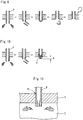
- each layer constituted of a fire-resistant resin composition effectively expands during burning, and, as shown in Fig. 11 , the residue caulks the gap between the pipe and the compartment pass-through portion and the inside of the pipe to prevent flame and smoke from penetrating to the other side partitioned by the floor material.
- the pipes are thus excellent in fire resistance and also excellent in molding properties and have mechanical strength sufficient as pipes.
- the present invention can impart fire resistance to the entire piping.
- the fire resistance was compared by an alternative evaluation technique in which heating is conducted under a condition that one end of a piping material protrudes in a fire-resistant furnace by 300 mm.
- the difference in fire resistance may be further distinguished.
- the pipe of the present invention rapidly and reliably caulks the compartment pass-through portion during burning, and also the entire pipe can undergo burning for a long period of time. Even if the pipe partially dropped during burning, it is suggested that the opening portion of the pipe is quickly caulked to maintain the shape, and thereby flame and smoke hardly penetrate to the outside of the burning chamber, resulting in prevention of the fire from spreading.
- the inner circumference surface of the piping material is smooth and thereby can allow fluid to smoothly pass, and also the inner circumference surface of the piping material is excellent in chemical proof and thereby hardly limits the type of fluid, which allows general purpose application.
- the outer circumference surface of the pipe is excellent in adhesion and, for example, can be easily and reliably connected to another member such as a pipe joint.
- the multilayered fire-resistant pipe of the present invention is not limited to the above-described Examples.
- the pipes have a nominal diameter of 100 mm, but may have a nominal diameter different therefrom.
Landscapes
- Engineering & Computer Science (AREA)
- General Engineering & Computer Science (AREA)
- Mechanical Engineering (AREA)
- Chemical & Material Sciences (AREA)
- Polymers & Plastics (AREA)
- Health & Medical Sciences (AREA)
- Chemical Kinetics & Catalysis (AREA)
- Medicinal Chemistry (AREA)
- Organic Chemistry (AREA)
- Structural Engineering (AREA)
- Life Sciences & Earth Sciences (AREA)
- Wood Science & Technology (AREA)
- Compositions Of Macromolecular Compounds (AREA)
- Rigid Pipes And Flexible Pipes (AREA)
- Laminated Bodies (AREA)
- Building Environments (AREA)
- Sink And Installation For Waste Water (AREA)
Description
- The present invention particularly relates to a fire-resistant pipe that is excellent in fire resistance and is used in a construction passing through a partition of a building.
- Buildings have fireproof compartments defined depending on the types and specifications of the buildings. In the fireproof compartments, according to the specifications, flooring materials and wall materials for fireproof construction or semi-fireproof construction prescribed by the Building Standards Act are used. The flooring materials and the wall materials for fireproof construction or semi-fireproof construction prescribed by the Building Standards Act are those defined by the Minister of Land, Infrastructure, Transport and Tourism or certified by the Minister of Land, Infrastructure, Transport and Tourism, and examples thereof include ferroconcrete; concrete blocks, brick constructions, and stone constructions that are reinforced with iron materials; iron materials covered with steel mortar or concrete on both surfaces thereof; lightweight foamed concrete; precast concrete plates; and laminates of plywood and gypsum board, hard wood chip cement board, or lightweight foamed concrete.
- Incidentally, buildings are provided with piping (such as electrical conduits, drain pipes, and ducts). Such piping passes through the above-mentioned fireproof compartment in some cases.
- When a through-hole through which piping or the like passes (hereinafter, referred to as "compartment pass-through portion") is provided to the above-mentioned fireproof compartment, occurrence of fire may cause a big fire accident within a short period of time by that the fire and smoke quickly penetrate from the room where the fire occurred to the next room having the fireproof compartment therebetween through the compartment pass-through portion.
- Therefore, the Building Standards Act establishes that only materials that passed a fire-resistant test for compartment pass-through and certified by the Minister of Land, Infrastructure, Transport and Tourism or evaluated by fire defense can be used as the pipe passing through the compartment pass-through portion in a building.
- Therefore, the compartment pass-through portion is provided with fire-protection measures for caulking a gap with a noncombustible material such as mortar after installing the piping passing through the compartment so that no gap is formed between the compartment pass-through portion and the piping.
- When the pipe is a metal, since the piping material itself is heat resistant and noncombustible, a sufficient effect is observed only by caulking the gap with a noncombustible material such as mortar, as described above. However, the metal piping has a large weight and therefore has a problem that the workability in transferring and in construction is inferior.
- On the other hand, when the pipe is a synthetic resin, the piping is light in weight, excellent in workability, and easy to bond, compared to the metal piping. The synthetic resin piping has thus various merits, but is inferior in heat resistance and fire resistance. Therefore, in fire, the pipe is lost by burning or is deformed by the heat to generate a gap between the compartment pass-through portion and the pipe, which may allow the heat, fire, and smoke occurred at one side of the fireproof compartment to reach the other side.
- Accordingly, for example, it is employed fire-protection measures in which a sheet-like covering material having fire-resistance and expansibility is wound on the outer surface of the synthetic resin pipe. As the fire-resistant resin composition constituting the sheet-like covering material, proposed are those in which a vinyl chloride-based resin is blended with heat-expandable graphite, an inorganic filler, and a plasticizer and also blended with a specific phosphorus compound (for example, refer to Patent Document 1) and those in which a base resin, such as rubber, a thermoplastic elastomer, or a liquid polymer, is blended with heat-expandable graphite serving as an inorganic expansion agent and also blended with a resin serving as a deformation-preventing resin, such as a polycarbonate resin or a polyphenylene sulfide resin (for example, refer to Patent Document 2).
- However, in the fire-protection measures using the sheet-like covering material, a synthetic resin pipe is temporarily installed, and then the sheet-like covering material is wound to the pipe at a portion previously determined. Subsequently, the pipe is supported and fixed, and then the opening is filled back with mortar. Therefore, the measures has a large number of work units and takes a long time and also has a problem that the adjustment of the piping position after the winding of the sheet-like covering material to the piping material is difficult.
- Accordingly, the above-mentioned problems can be solved by directly producing a pipe with a resin composition having fire-resistance and expansibility, but since the fire-resistant resin composition in
Patent Document 1 contains large amounts of an inorganic filler and a plasticizer in a vinyl chloride-based resin, the pipe formed therewith cannot obtain a high mechanical strength that is an indispensable requirement in a pipe. Furthermore, since the fire-resistant resin composition inPatent Document 2 contains rubber, a thermoplastic elastomer, or a liquid polymer as the base resin, the piping material formed therewith cannot obtain a high mechanical strength that is an indispensable requirement in a pipe, as in the fire-resistant resin composition ofPatent Document 1. -
- [Patent Document 1] Japanese Unexamined Patent Application Publication No.
2006-348228 - [Patent Document 2] Japanese Patent No.
3133683 - The present invention has been proposed in the light of the above-mentioned problems, and it is an object thereof to provide a fire-resistant pipe that can be fire-protection measures by itself.
- In order to solve the above-mentioned problems, a multilayered fire-resistant pipe according to
claim 1 is provided. - One embodiment of the invention 10 provides a multilayered fire-resistant piping material including a tubular fire-resistant expandable layer made of a heat-expandable fire-resistant resin composition and a covering layer covering at least one of the outer surface and the inner surface of the fire-resistant expandable layer. The fire-resistant expandable layer is formed of a fire-resistant resin composition containing heat-expandable graphite having a pH of 1.5 to 4.0 in an amount of 1 to 15 parts by weight based on 100 parts by weight of a polyvinyl chloride-based resin, and the covering layer is formed of a polyvinyl chloride-based resin composition not containing heat-expandable fire-resistant materials.
- In a multilayered fire-resistant piping material of the invention, the fire-resistant resin composition contains an additive for providing heat stability during molding.
- A multilayered fire-resistant pipe of the invention, includes at least one selected from the group consisting of lead-based stabilizers, organic tin-based stabilizers, and higher fatty acid metal salts as the additive for providing heat stability during molding in a total additive amount of 0.3 to 5.0 parts by weight based on 100 parts by weight of the polyvinyl chloride-based resin.
- A multilayered fire-resistant pipe of the invention, further includes a basic compound as the additive for providing heat stability during molding in a total additive amount of 0.3 to 5.0 parts by weight based on 100 parts by weight of the polyvinyl chloride-based resin.
- One embodiment of the invention provides a multilayered fire-resistant pipe including a tubular fire-resistant expandable layer made of a heat-expandable fire-resistant resin composition and a covering layer covering at least one of the outer surface and the inner surface of the fire-resistant expandable layer. The fire-resistant expandable layer is constituted of a fire-resistant resin composition containing heat-expandable graphite having an expansion volume in the range of 100 to 250 mL/g in an amount of 1 to 15 parts by weight based on 100 parts by weight of a polyvinyl chloride-based resin, and the covering layer is constituted of a polyvinyl chloride-based resin composition not containing heat-expandable fire-resistant materials, and the covering layer is constituted of a polyvinyl chloride-based resin composition not containing heat-expandable fire-resistant materials.
- One embodiment of the invention provides a multilayered fire-resistant piping material including a tubular fire-resistant expandable layer formed of a heat-expandable fire-resistant resin composition and a covering layer covering at least one of the outer surface and the inner surface of the fire-resistant expandable layer. The fire-resistant expandable layer is constituted of a fire-resistant resin composition containing heat-expandable graphite having a 1.3-time expansion temperature of 180 to 240°C in an amount of 1 to 15 parts by weight based on 100 parts by weight of a polyvinyl chloride-based resin, and the covering layer is constituted of a polyvinyl chloride-based resin composition not containing heat-expandable fire-resistant materials.
- A multilayered fire-resistant pipe of the invention, when the pipe is constructed so as to pass through a flooring material and is subjected to a fire-resistant test (complying with ISO 834-1) in which the underside of the floor is heated under conditions that one end of the pipe is exposed to a heating side by 300 mm from the surface on the heating side of the flooring material and that the other end of the pipeis exposed to a non-heating side by 800 mm from the surface on the non-heating side of the flooring material, a pipe inner cross-sectional area S1 at the end of the pipe before burning on the heating side and a pipe inner cross-sectional area S2 at a minimum inner diameter of the pipe after burning satisfy a relationship:

- In a multilayered fire-resistant pipe of the invention, the covering layer is provided on each of the outer surface and the inner surface of the fire-resistant expandable layer.
- In an embodiment of the invention, 1 to 15 parts by weight of heat-expandable graphite is blended with 100 parts by weight of a polyvinyl chloride-based resin. This is because that when the amount of the heat-expandable graphite is smaller than 1 part by weight, a sufficient heat expansibility cannot be obtained during burning, which causes insufficient caulking of the inside of a pipe, ascending of hot air through the inside of the pipe, and a decrease in fire-resistance performance. On the other hand, when the amount of the heat-expandable graphite is larger than 15 parts by weight, the heated composition is thermally expanded too much to maintain the shape, resulting in dropping of the residue to decrease the fire-resistance. Herein, the amount of the heat-expandable graphite is preferably 1 to 12 parts by weight and further preferably 2 to 10 parts by weight.
- The heat-expandable graphite used in the present invention is a crystalline compound maintaining a layer structure of carbon and is obtained by acid treatment of a powder such as natural flake graphite, pyrolytic graphite, or Kish graphite by inserting an inorganic acid between layers of the graphite using an inorganic acid such as concentrated sulfuric acid, nitric acid, or selenic acid and a strong oxidant such as concentrated nitric acid, perchloric acid, perchlorate, permanganate, dichromate, or hydrogen peroxide.
- The heat-expandable graphite having a pH of 1.5 to 4.0 is prepared by adjusting the pH after the acid treatment described above. The pH adjustment of the heat-expandable graphite is not particularly limited, but, in the state after acid treatment by inserting an inorganic acid between layers of raw material graphite as in above, the pH is usually 1 or less. Therefore, for example, the acid-treated graphite is washed with water for removing the remaining acid on the surface of the graphite, followed by drying. That is, the pH of the heat-expandable graphite can be increased by repeating washing with water and drying.
- In an embodiment of the invention, heat-expandable graphite that is adjusted to acidic is used. This is because that the fire-resistance performance is improved by preventing burning by effectively carbonizing a polyvinyl chloride resin during burning. This is based on a property of a polyvinyl chloride-based resin that repeats a hydrogen chloride elimination reaction in the presence of an acid to generate a flame-retardant carbide. However, when the pH of heat-expandable graphite is lower than 1.5, the too strong acidity may, for example, cause corrosion of a molding apparatus. On the other hand, when the pH of heat-expandable graphite is higher than 4.0, the effect of accelerating the carbonization of a polyvinyl chloride-based resin is low, which may cause insufficient fire-resistance performance. Accordingly, it is determined to use heat-expandable graphite having a pH of 1.5 to 4.0.
- Examples of the polyvinyl chloride-based resin used in the invention include polyvinyl chloride homopolymers; copolymers of vinyl chloride monomers and monomers having unsaturated bonds that are copolymerizable with the vinyl chloride monomers; and graft copolymers in which vinyl chloride is graft-copolymerized with (co)polymers other than vinyl chloride. These may be used alone or in a combination of two or more. In addition, the polyvinyl chloride-based resin may be chlorinated, according to need.
- The monomers having unsaturated bonds that are copolymerizable with the vinyl chloride monomers are not particularly limited, and examples thereof include α-olefins such as ethylene, propylene, and butylene; vinyl esters such as vinyl acetate and vinyl propionate; vinyl ethers such as butylvinyl ether and cetylvinyl ether; (meth)acrylic acid esters such as methyl (meth)acrylate, ethyl (meth)acrylate, and butyl acrylate; aromatic vinyls such as styrene and α-methyl styrene; and N-substituted maleimides such as N-phenyl maleimide and N-cyclohexyl maleimide. These may be used alone or in a combination of two or more.
- Any (co)polymer that can graft-(co)polymerize vinyl chloride can be used for graft-copolymerizing the vinyl chloride without particular limitation, and examples thereof include ethylene-vinyl acetate copolymers, ethylene-vinyl acetate-carbon monoxide copolymers, ethylene-ethyl acrylate copolymers, ethylene-butyl acrylate-carbon monoxide copolymers, ethylene-methyl methacrylate copolymers, ethylene-propylene copolymers, acrylonitrile-butadiene copolymers, polyurethane, polyethylene chloride, and polypropylene chloride. These may be used alone or in a combination of two or more.
- The average degree of polymerization of the polyvinyl chloride-based resin is not particularly limited, but is preferably 400 to 1600 and most preferably 600 to 1400, since a low average degree of polymerization causes a decrease in physical properties of a molded article, and a high average degree causes an increase in melting viscosity to make molding difficult. In addition, the above-mentioned "average degree of polymerization" refers to an average degree of polymerization measured in conformity with JIS K-6721 "testing method for vinyl chloride resin" using a resin sample prepared by dissolving a composite vinyl chloride-based resin in tetrahydrofuran (THF), filtering the solution for removing insoluble components, and then removing the THF in the filtrate by drying.
- The polymerization method of the polyvinyl chloride-based resin is not particularly limited. Any known polymerization method may be employed, and examples thereof include a bulk polymerization method, a solution polymerization method, an emulsion polymerization method, and a suspension polymerization method.
- The chlorination method of the polyvinyl chloride-based resin is not particularly limited. Any known chlorination method may be employed, and examples thereof include thermal chlorination and photochlorination.
- The polyvinyl chloride-based resin may be cross-linked or modified within the range that does not impair the fire-resistance performance as a resin composition. In such a case, a resin that is cross-linked or modified in advance may be used, or the cross-linking or modification may be simultaneously performed when an additive or other component is blended. Alternatively, the cross-linking or modification may be performed after blending of the additive or other component with the resin. The cross-linking of the resin may be performed by any method without particular limitation, and a usual cross-linking method of a polyvinyl chloride-based resin, such as cross-linking using various types of cross-linking agents or oxides, cross-linking by electron beam irradiation, or a method using a water cross-linking agent, may be employed.
- In one embodiment of the invention, the total additive amount of the group consisting of lead-based stabilizers, organic tin-based stabilizers, and higher fatty acid metal salts is 0.3 to 5.0 parts by weight based on 100 parts by weight of the polyvinyl chloride-based resin. This is because that when the total additive amount of the group consisting of lead-based stabilizers, organic tin-based stabilizers, and higher fatty acid metal salts is smaller than 0.3 parts by weight, the heat stability of the polyvinyl chloride-based resin is difficult to be ensured during molding, which may cause easy generation of carbides during molding. On the other hand, when the total additive amount of the group consisting of lead-based stabilizers, organic tin-based stabilizers, and higher fatty acid metal salts is larger than 5.0 parts by weight, the acceleration of the carbonization of the polyvinyl chloride-based resin during burning is inhibited, which may cause insufficient fire-resistance performance.
- Examples of the lead-based stabilizers include white lead, basic lead sulfite, tribasic lead sulfate, dibasic lead phosphite, dibasic lead phthalate, tribasic lead maleate, a coprecipitate of silica gel and lead silicate, dibasic lead stearate, lead stearate, and lead naphthalate.
- Examples of the organic tin-based stabilizers include mercaptides such as dibutyltin mercapto, dioctyltin mercapto, and dimethyltin mercapto; maleates such as dibutyltin maleate, dibutyltin maleate polymers, dioctyltin maleate, and dioctyltin maleate polymers; and carboxylates such as dibutyltin mercapto, dibutyltin laurate, and dibutyltin laurate polymers.
- Examples of the higher fatty acid metal salts include lithium stearate, magnesium stearate, calcium stearate, calcium laurate, calcium ricinoleate, strontium stearate, barium stearate, barium laurate, barium ricinoleate, cadmium stearate, cadmium laurate, cadmium ricinoleate, cadmium naphthenate, cadmium 2-ethylhexanoate, zinc stearate, zinc laurate, zinc ricinoleate, zinc 2-ethylhexanoate, lead stearate, dibasic lead stearate, and lead naphthenate.
- In one embodiment of the invention, the amount of the basic compound is 0.3 to 5.0 parts by weight based on 100 parts by weight of the polyvinyl chloride-based resin. This is because that when the additive amount of the basic compound is smaller than 0.3 parts by weight, the heat stability of the polyvinyl chloride-based resin is difficult to be ensured during molding, which may cause easy generation of carbides during molding. On the other hand, when the additive amount of the basic compound is larger than 5.0 parts by weight, the acceleration of carbonization of the polyvinyl chloride-based resin during burning is inhibited, which may cause insufficient fire-resistance performance.
- The basic compound is not particularly limited, and examples thereof include calcium carbonate, calcium silicate, calcium hydroxide, calcium oxide, magnesium carbonate, magnesium hydroxide, magnesium oxide, barium carbonate, aluminum hydroxide, zinc oxide, zinc hydroxide, and iron oxide.
- In the invention, the term "expansion volume of the heat-expandable graphite" refers to the volume per gram of heat-expandable graphite after heat expansion.
- The expansion volume of heat-expandable graphite is determined by the following process:
- 1) One gram of a sample is put in a 500-cc. beaker that is heated in advance for 20 minutes or more in a heating furnace and is heated in the heating furnace (furnace temperature: 1000°C);
- 2) After 30 seconds, the beaker is taken out from the heating furnace;
- 3) The sample in the beaker is cooled to room temperature;
- 4) The weight and the volume of the sample after expansion are measured; and
- 5) The value of (volume of the sample after expansion)/(weight of the sample after the expansion) is calculated.
- The expansion volume of heat-expandable graphite varies depending on the type and amount of the interlayer compound of the heat-expandable graphite and on the particle diameter of the heat-expandable graphite itself, and is a very important factor for exhibiting fire-resistance.
- In the invention, the expansion volume of heat-expandable graphite is 100 to 250 mL/g. This is because that when the expansion volume of heat-expandable graphite is smaller than 100 mL/g, the expansion volume is too small to achieve sufficient fire-resistance, which requires a large amount of heat-expandable graphite for increasing the fire-resistance and may cause defects in, for example, physical properties or molding properties. On the other hand, when the expansion volume of heat-expandable graphite is larger than 250 mL/g, the heated composition is thermally expanded too much to maintain the shape, which may cause dropping of the residue and a decrease in the fire-resistance. Herein, the expansion volume of heat-expandable graphite is preferably 120 to 2.30 mL/g and more preferably 140 to 220 mL/g.
- In one embodiment of the invention, the 1.3-time expansion temperature of heat-expandable graphite is a temperature of a heating furnace when a sample of heat-expandable graphite is heated for 30 minutes in the furnace in which the temperature is kept constant and the expansion magnification of the sample is 1.3 times or more at the temperature.
- In addition, expansion magnification is defined by (volume of sample after heating)/(volume of sample before heating).
- The resin temperature during molding refers to the highest temperature of the resin during melting.
- In one embodiment of the invention, the 1.3-time expansion temperature of heat-expandable graphite is 180 to 240°C. This is because that when the 1.3-time expansion temperature of heat-expandable graphite is lower than 180°C, the heat-expandable graphite may expand during molding, which causes a defect in appearance of a pipe and also may decrease the fire-resistance during burning. On the other hand, when the 1.3-time expansion temperature of heat-expandable graphite is higher than 240°C, there is no risk of starting of expansion of the heat-expandable graphite during molding, but thermal decomposition (foaming) of the polyvinyl chloride-based resin progresses during burning. Therefore, since the heat-expandable graphite expands after a reduction in plasticity of the polyvinyl chloride-based resin, the polyvinyl chloride-based resin may not bear the expansion of the heat-expandable graphite to be broken to pieces.
- The fire-resistant test in the invention is carried out according to an evaluation method of a performance test for pipe passing through, for example, a fireproof compartment, based on the revised Building Standards Act in force on June 1, 2000 (Heisei 12). The flooring material used was PC (precast concrete) plate (length: 600 mm, width: 1200 mm, thickness: 100 mm), which is a flooring material of fireproof construction or semi-fireproof construction prescribed by the Building Standards Act.
- Examples of the flooring material to be used include, in addition to the PC plate, the followings:
- 1) A wood frame member in which a gypsum board (thickness: 9.5 mm) is bonded to the upper surface of a structural plywood (thickness: 12 mm) and a reinforced gypsum board (thickness: 15 mm) is bonded to the lower surface of the plywood;
- 2) A wood frame member in which a gypsum board (thickness: 12.5 mm) is bonded to the upper surface of a structural plywood (thickness: 12 mm) and two reinforced gypsum boards (thickness: 12.5 mm) are bonded to the lower surface of the plywood;
- 3) A lightweight foamed concrete (ALC) plate having a thickness of 100 mm or more; and
- 4) A precast concrete (PC) plate having a thickness of 70 mm or more. In particular, the ALC plate and the PC plate having a thickness of 100 mm or more are preferred.
- The gap between the pipe and the compartment pass-through portion was caulked with mortar. One end of the pipe was exposed to a heating side by 300 mm from the surface on the heating side of the flooring material, and the other end of the pipe was exposed to a non-heating side by 800 mm from the surface on the non-heating side of the flooring material.
- The furnace used in the fire-resistant test had a structure that can heat one surface of a floor material and can almost uniformly give a temporal change in temperature based on the following
Expression 1 complying with regulation of ISO 834-1 to all over the entire test surface of the floor material, when the surface on the heating side of the floor material was the test surface. - That is, the fire-resistant test furnace was provided with a thermocouple (hereinafter, referred to as "furnace thermocouple") for measuring temperature in the furnace at a position apart from the floor material by 100 to 300 mm such that one to ten hot junctions were arranged uniformly with respect to the test surface of the floor material.
- Then, according to the regulation of ISO 834-1, the fire-resistant test furnace was heated so that the temporal change in temperature (hereinafter, referred to as "heating temperature") measured by the thermocouple can be expressed by a numerical value represented by the following Expression 1:

Expression 1, T denotes an average temperature (°C) in the furnace, and t denotes elapsed time (minute) in the test, and the temperature was measured within every one minute period. - Regarding the pipe inner cross-sectional area S1 at the end on the heating side of the pipe before burning, the pipe is measured for inner diameters at least in two directions before starting of the fire-resistance test to calculate the average inner diameter, and then the pipe inner cross-sectional area S1 is calculated. Regarding the pipe inner cross-sectional area S2 at the minimum inner diameter portion of the pipe after burning, after starting of the fire-resistance test, when smoke appears from the gap between the compartment pass-through portion and the pipe on the non-heating side, the burning in the fire-resistant test furnace is terminated, and then the flooring material panel is immediately removed from the fire-resistant furnace. After cooling of the pipe, the caulked pipe is observed from the heating side to determine the projected area S2 thereof. The S2 may be measured by any method such as the followings:
- a method by image analysis of a photograph taken from the heating side, or
- a method by sketching a projected portion on a paper, cutting out the sketched portion and weighing the cut-out paper, and determining the S2 by proportional calculation based on the weight of the paper of which weight per unit area is already known.
- When no smoke was observed for 2 hours, the test is terminated after 2 hours, and the S2 is measured by the above-mentioned process.
- In one embodiment of the invention, the value obtained by the Expression of (S2/S1)×100 represents a pipe inner cross-sectional area proportion (%) after burning. In one embodiment of the invention, the pipe inner cross-sectional area proportion is 50% or less. This is because that when the pipe inner cross-sectional area proportion is larger than 50%, the pass-through portion in a pipe after burning cannot be effectively caulked, which may not give a desired fire-resistance performance.
- In one embodiment of the invention, additives, such as a flame retardant, a stabilizer, a lubricant, a processing aid, an impact modifier, a heat-resistance-improving agent, an antioxidant, a light stabilizer, an ultraviolet absorber, a pigment, a plasticizer, and a thermoplastic elastomer, may be added within a range that does not impair the physical properties.
- As the flame retardant, any flame retardant that increases flame retardancy during burning can be used without particular limitation, and examples thereof include hydroxides such as aluminum hydroxide and magnesium hydroxide; hydrotalcite; antimony oxides such as antimony dioxide, antimony trioxide, and antimony pentoxide; molybdenum compounds such as molybdenum trioxide, molybdenum disulfide, and ammonium molybdate; bromine-based compounds such as tetrabromobisphenol A, tetrabromethane, tetrabromethane, tetrabromethane, and tetrabromethane; phosphorus-based compounds such as triphenyl phosphate and ammonium polyphosphate; calcium borate; and zinc borate. From the viewpoint of the effect of preventing burning of polyvinyl chloride, antimony trioxide is particularly preferred, because antimony compounds generate halogenated antimony compounds in the presence of halogenated compounds under high temperature conditions and prevent a burning cycle with a very high effect, and the synergetic effect thereof is significant.
- By using the flame retardant, the synergetic effect between the heat-insulating effect by the expansion of heat-expandable graphite and the flame-retarding effect by the flame retardant can more efficiently improve the fire-resistance performance during burning. The additive amount of the flame retardant is not particularly limited, but is preferably 1 part by weight or more and 20 parts by weight or less based on 100 parts by weight of the polyvinyl chloride-based resin. When the amount of the flame retardant is less than 1 part by weight, sufficient synergetic effect may not be obtained. When the amount of the flame retardant is higher than 20 parts by weight, the molding properties and the physical properties may be significantly decreased.
- The stabilizer is not particularly limited, and examples thereof include heat stabilizers and heat stabilization aids. The heat stabilizers are not particularly limited, and example thereof include organic tin-based stabilizers such as dibutyltin mercapto, dioctyltin mercapto, dimethyltin mercapto, dibutyltin mercapto, dibutyltin maleate, dibutyltin maleate polymers, dioctyltin maleate, dioctyltin maleate polymers, dibutyltin laurate, and dibutyltin laurate polymers; lead-based stabilizers such as lead stearate, dibasic lead phosphate, and tribasic lead sulfate; calcium-zinc-based stabilizers; barium-zinc-based stabilizers; and barium-cadmium-based stabilizers. These may be used alone or in a combination of two or more.
- The heat stabilization aids are not particularly limited, and examples thereof include epoxidized soybean oil, phosphate esters, polyols, hydrotalcite, and zeolite. These may be used alone or in a combination of two or more.
- The lubricant includes an inner lubricant and an outer lubricant.
- The inner lubricant is used for reducing the fluid viscosity of a melting resin during a molding process to prevent friction heat generation. The inner lubricant is not particularly limited, and examples thereof include butyl stearate, lauryl alcohol, stearyl alcohol, epoxidized soybean oil, glycerin monostearate, stearic acid, and bisamides. These may be used alone or in a combination of two or more.
- The outer lubricant is used for accelerating sliding effect between a melting resin and a metal surface during a molding process. The outer lubricant is not particularly limited, and examples thereof include paraffin wax, polyolefin wax, ester wax, and montanoic acid wax. These may be used alone or in a combination of two or more.
- The processing aid is not particularly limited, and examples thereof include acryl-based processing aids such as alkyl acrylate-alkyl methacrylate copolymers having a weight average molecular weight of 100000 to 2000000. The acryl-based processing aids are not particularly limited, and examples thereof include n-butyl acrylate-methyl methacrylate copolymers and 2-ethylhexyl acrylate-methyl methacrylate-butyl methacrylate copolymers. These may be used alone or in a combination of two or more.
- The impact modifier is not particularly limited, and examples thereof include methyl methacrylate-butadienestyrene (MBS) copolymers, polyethylene chloride, and acrylic rubber.
- The heat-resistance-improving agent is not particularly limited, and examples thereof include α-methylstyrene-based and N-phenylmaleimide-based resins.
- The antioxidant is not particularly limited, and examples thereof include phenol-based antioxidants.
- The light stabilizer is not particularly limited, and examples thereof include hindered amine light stabilizers.
- The ultraviolet absorber is not particularly limited, and examples thereof include salicylic acid ester-based, benzophenone-based, benzotriazole-based, and cyanoacrylate-based ultraviolet absorbers.
- The pigment is not particularly limited, and examples thereof include organic pigments such as azo-based, phthalocyanine-based, surene-based, and dye lake-based pigments; and inorganic pigments such as oxide-based, molybdenum chromate-based, sulfide/selenide-based, and ferrocyanide-based pigments.
- The polyvinyl chloride-based resin may contain a plasticizer, but since the plasticizer may decrease the heat-resistance and fire-resistance of a molded article, the amount thereof is preferably small.
- The plasticizer is not particularly limited, and examples thereof include dibutyl phthalate, di-2-ethylhexyl phthalate, and di-2-ethylhexyl adipate.
- The thermoplastic elastomer is not particularly limited, and examples thereof include acrylnitrile-butadiene (NBR) copolymers, ethylene-vinyl acetate (EVA) copolymers, ethylene-vinyl acetate-carbon monoxide (EVACO) copolymers, vinyl chloride-based thermoplastic elastomers such as vinyl chloride-vinyl acetate copolymers and vinyl chloride-vinylidene chloride copolymers, styrene-based thermoplastic elastomers, olefin-based thermoplastic elastomers, urethane-based thermoplastic elastomers, polyester-based thermoplastic elastomers, and polyamide-based thermoplastic elastomers. These thermoplastic elastomers may be used alone or in a combination of two or more.
- The method for mixing the additives with the polyvinyl chloride-based resin is not particularly limited, and examples thereof include a method by hot-blending and a method by cold blending.
- The fire-resistant pipe of the present invention is molded with an extruder or an injection molder that is usually used. The type and the screw shape of the molder are not particularly limited as long as sufficient kneading can be performed, considering the tensile strength and the impact, and an extruder allowing continuous molding is preferred.
- The multilayered fire-resistant pipe of the invention includes a covering layer formed of a polyvinyl chloride-based resin composition not containing heat-expandable graphite on at least one of the outer surface and the inner surface of the fire-resistant expandable layer. Therefore, the multilayered fire-resistant pipe is further excellent in the molding properties and can be continuously produced with high size accuracy by, for example, injection molding or extrusion molding.
- Furthermore, the fire-resistant expandable layer contains a polyvinyl chloride-based resin as a main component and thereby has sufficient mechanical strength and chemical proof necessary as a piping material.
- In addition, since the base resins of both the fire-resistant expandable layer and the covering layer constituting the pipe are polyvinyl chloride-based resins, the affinity between the layers is high. Therefore, the layers are tightly adhered to each other at the interface, resulting in providing of excellent water cutoff performance. Consequently, when the multilayered fire-resistant pipes of the present invention are connected to each other with a pipe joint, the treatment of the end of the pipe is unnecessary, resulting in dramatic improvement in construction workability.
- When the outer surface of the fire-resistant expandable layer is covered with a covering layer formed of a polyvinyl chloride-based resin composition not containing a heat-expandable fire-resistant material, the outer circumference surface of the piping material is excellent in adhesion and, for example, can be easily and reliably connected to another member such as a pipe joint.
- When the inner surface of the fire-resistant expandable layer is covered with a covering layer formed of polyvinyl chloride-based resin composition not containing a heat-expandable fire-resistant material, the inner circumference surface of the pipe is smooth to allow fluid to smoothly pass. In addition, since the inner circumference surface of the pipe is excellent in chemical proof, the pipe hardly limits the type of fluid, which allows general purpose application.
- Since the multilayered fire-resistant pipe of one embodiment of the invention includes the covering layer on each of the outer surface and the inner surface of the fire-resistant expandable layer, the outer circumference surface of the pipe is excellent in adhesion and, for example, can be easily and reliably connected to another member such as a pipe joint, and also the inner circumference surface of the pipe is excellent in chemical proof, and thereby the piping material hardly limits the type of fluid, which allows general purpose application.
-
- [
Fig. 1] Fig. 1 is a cross-sectional view of a single-layered fire-resistant pipe P1. - [
Fig. 2] Fig. 2 is a cross-sectional view of a multilayered fire-resistant pipe P2 according to an embodiment of the present invention. - [
Fig. 3] Fig. 3 is a cross-sectional view of a multilayered fire-resistant pipe P3 according to an embodiment of the present invention. - [
Fig. 4] Fig. 4 is a cross-sectional view of a multilayered fire-resistant pipe P4 according to an embodiment of the present invention. - [
Fig. 5] Fig. 5 is an explanatory drawing simply showing a structure of a fire-resistant test furnace X used in a fire-resistant test. - [
Fig. 6] Fig. 6 is an explanatory drawing showing a pipe inner cross-sectional area S1 of a pipe P, before burning, of the invention. - [
Fig. 7] Fig. 7 is an explanatory drawing showing a pipe inner cross-sectional area S2 of the pipe P, after burning, of the invention. - [
Fig. 8] Fig. 8 is an explanatory drawing showing the state that a conventional pipe P was thermally expanded by heating and could not maintain the shape to drop the residue. - [
Fig. 9] Fig. 9 is an explanatory drawing schematically showing the state of burning of a conventional pipe P constructed so as to pass through a flooring material. - [
Fig. 10] Fig. 10 is an explanatory drawing schematically showing the state of burning of a pipe P according to the present invention constructed so as to pass through a flooring material. - [
Fig. 11] Fig. 11 is an explanatory drawing showing the state of a pipe P according to the present invention that holds the shape to maintain the fire resistance after being thermally expanded by heating. - A single-layered fire-resistant pipe P1 (reference) is composed of a fire-resistant resin composition alone, as shown in
Fig. 1 . - The reference pipe will be described in detail with reference to examples below.
- In Reference Examples 1 to 16 and Comparative Examples 1 to 5, the following materials were used:
- Vinyl chloride resin (manufactured by Taiyo Vinyl Corp., trade name: "TH1000");
- Heat-expandable graphite (manufactured by Tosoh Corp., trade name: "GREP-EG");
- Calcium carbonate (manufactured by Shiraishi Calcium Kaisha, Ltd., trade name: "Whiton SB");
- Lead-based stabilizer (manufactured by Sakai Chemical Industry Co., Ltd., trade name: "SL-1000"); and
- Lubricant (manufactured by Mitsui Chemicals, Inc., trade name: "Hiwax 4202E").
- In Reference Examples 17 to 41 and Comparative Examples 6 to 15, the following materials were used:
- Vinyl chloride resin (manufactured by Tokuyama Sekisui Co., Ltd, trade name: "TS1000R");
- Heat-expandable graphite (manufactured by Chuetsu Graphite Works Co., Ltd., trade name: "SFF");
- Lead-based stabilizer: lead stearate (manufactured by Mizusawa Industrial Chemicals, Ltd., trade name: "StabinexNC18");
- Organic tin-based stabilizer: octyltin mercapto (manufactured by Sankyo Organic Chemicals Co., Ltd., trade name: "ONE-100F");
- Higher fatty acid metal salt: Ca/Zn-based composite stabilizer (manufactured by Sakai Chemical Industry Co., Ltd., trade name: "NWP-6000");
- Basic compound: calcium carbonate (manufactured by Shiraishi Calcium Kaisha, Ltd., trade name: "Whiton SB"), magnesium hydroxide (manufactured by Kyowa Chemical Industry Co., Ltd., trade name: "KISUMA5A");
- Hydrotalcite (manufactured by Kyowa Chemical Industry Co., Ltd., trade name: "DHT-4A");
- Epoxidized soybean oil (manufactured by ADEKA Corp., trade name: "Adekacizer 0130P"); and
- Lubricant (manufactured by Mitsui Chemicals Inc., trade name: "Hiwax 4202E").
- The pH of the heat-expandable graphite was confirmed by the following method:
- 1) A graphite mixture is prepared by adding 25 mL of ion-exchange water to 5 g of a heat-expandable graphite sample;
- 2) The resulting graphite mixture is stirred with a glass rod for 30 seconds; and
- 3) After leaving the solution for 20 minutes, the pH of the graphite mixture is measured with a pH meter (manufactured by Horiba, Ltd., trade name: "pH/ION METER F-23").
- The pH of the heat-expandable graphite was adjusted by the following method:
- The heat-expandable graphite was put in a beaker, and ion exchange water was added thereto, followed by stirring. The acid remaining on the surface of the heat-expandable graphite was removed by washing, while the pH of the graphite mixture was confirmed with the pH meter. Then, the graphite mixture was filtered, followed by drying in a thermostatic chamber to give heat-expandable graphite having a desired pH. When a desired pH was not obtained by washing once, the washing and drying processes were repeated.
- In Reference Examples 42 to 57 and Comparative Examples 16 to 18, the following materials were used:
- Vinyl chloride resin (manufactured by Tokuyama Sekisui Co., Ltd., trade name: "TS1000R");
- Heat-expandable graphite (expansion volume: 65 mL/g): (manufactured by Sanyo Trading Co., Ltd., trade name: "SYZR1003");
- Heat-expandable graphite (expansion volume: 100 mL/g): (grain size-controlled product);
- Heat-expandable graphite (expansion volume: 150 mL/g): (manufactured by Sanyo Trading Co., Ltd., trade name: "SYZR1002");
- Heat-expandable graphite (expansion volume: 180 mL/g): (manufactured by Chuetsu Graphite Works Co., Ltd., trade name: "SFF");
- Heat-expandable graphite (expansion volume: 190 mL/g): (manufactured by Sanyo Trading Co., Ltd., trade name: "SYZR502");
- Heat-expandable graphite (expansion volume: 200 mL/g): (manufactured by Sanyo Trading Co., Ltd., trade name: "SYZR802");
- Heat-expandable graphite (expansion volume: 250 mL/g): (grain size-controlled product);
- Heat-expandable graphite (expansion volume: 275 mL/g): (manufactured by Sanyo Trading Co., Ltd., trade name: "SYZR322");
- Calcium carbonate (manufactured by Shiraishi Calcium Kaisha, Ltd., trade name: "Whiton SB");
- Organic tin-based stabilizer (manufactured by Sankyo Organic Chemicals Co., Ltd., trade name: "ONZ-142F");
- Lubricant (manufactured by Mitsui Chemicals Inc., trade name: "Hiwax 220MP"); and
- Stearic acid (manufactured by Kao Corp., trade name: "S-30").
- In Reference Examples 58 to 70 and Comparative Examples 19 and 20, the following materials were used:
- Vinyl chloride resin (manufactured by Tokuyama Sekisui Co., Ltd., trade name: "TS1000R");
- Heat-expandable graphite (manufactured by Chuetsu Graphite Works Co., Ltd., trade name: "SFF", expansion volume: 180 mL/g);
- Calcium carbonate (manufactured by Shiraishi Calcium Kaisha, Ltd., trade name: "Whiton SB");
- Lead-based stabilizer (manufactured by Sakai Chemical Industry Co., Ltd., trade name: "SL-1000"); and
- Lubricant (manufactured by Mitsui Chemicals Inc., trade name: "Hiwax 4202E").
- In Reference Examples 71 to 75 and Comparative Examples 21 and 22, the following materials were used:
- Vinyl chloride resin (manufactured by Taiyo Vinyl Corp., trade name: "TH1000");
- Heat-expandable graphite (1.3-time expansion temperature-controlled product);
- Lead-based stabilizer (manufactured by Sakai Chemical Industry Co., Ltd., trade name: "SL-1000"); and
- Lubricant (manufactured by Mitsui Chemicals Inc., trade name: "Hiwax 4202E").
- Then, the above-mentioned materials were mixed at ratios shown in Tables 1 to 14, and each mixture was stirred and mixed in a Henschel mixer having a capacity of 200 liters (manufactured by Kawada Industries, Inc.) to give a resin composition. The resulting resin composition was extrusion molded with a generally used extruder to a test pipe P to be used for fire-resistance evaluation. The resin temperature during molding for those that are not shown in the Tables was 180°C.
- As shown in
Fig. 1 , the test pipe P was formed so as to have a length of 1200 mm, an outer diameter of 114 mm, a thickness of 6.6 mm, and a nominal diameter of 100 mm. - Furthermore, test pieces to be used for performance evaluation and heat expansibility evaluation were produced from the test pipe P by cutting out a part of the pipe wall of the test pipe P, press-molding the cut-out pipe wall with a load of 200 kgf at 190°C for 3 minutes to a press plate having a thickness of 3 mm, and cutting the press plate into 1-cm square pieces.
- A multilayered fire-resistant piping material P2 of a first embodiment according to the present invention is constituted of a fire-resistant
expandable layer 11 and an innerside covering layer 12 covering the inner circumference surface of the fire-resistantexpandable layer 11, as shown inFig. 2 . A multilayered fire-resistant pipe P3 of a second embodiment according to the present invention is constituted of a fire-resistantexpandable layer 11, an innerside covering layer 12 covering the inner circumference surface of the fire-resistantexpandable layer 11, and an outerside covering layer 13 covering the outer circumference surface of the fire-resistantexpandable layer 11, as shown inFig. 3 . - Furthermore, a multilayered fire-resistant pipe P4 of a third embodiment according to the present invention is constituted of a fire-resistant
expandable layer 11 and an outerside covering layer 13 covering the outer circumference surface of the fire-resistantexpandable layer 11, as shown inFig. 4 . - The present invention will be described in detail with reference to Examples below.
- In Examples 76 to 98 and Comparative Examples 23 to 32, the following materials were used:
- Vinyl chloride resin (manufactured by Taiyo Vinyl Corp., trade name: "TH1000");
- Heat-expandable graphite (manufactured by Tosoh Corp., trade name: "GREP-EG", 1.3-time expansion temperature: 210°C);
- Lead-based stabilizer (manufactured by Sakai Chemical Industry Co., Ltd., trade name: "SL-1000");
- Lubricant (manufactured by Mitsui Chemicals, Inc., trade name: "Hiwax 4202E");
- Calcium carbonate (Shiraishi Calcium Kaisha, Ltd., trade name: "Whiton SB"); and
- Ammonium polyphosphate (Sumitomo Chemical Co., Ltd., trade name: "Sumisafe P").
- Examples 99 to 120 and Comparative Examples 33 to 35 Vinyl chloride resin (manufactured by Taiyo Vinyl Corp., trade name: "TH1000");
Heat-expandable graphite (1.3-time expansion temperature-controlled product);
Lead-based stabilizer (manufactured by Sakai Chemical Industry Co., Ltd., trade name: "SL-1000");
Lubricant (manufactured by Mitsui Chemicals, Inc., trade name: "Hiwax 4202E"); and
Calcium carbonate (manufactured by Shiraishi Calcium Kaisha, Ltd., trade name: "Whiton SB"). - Then, the resulting resin composition was extrusion molded with a generally used extruder to a test piping material P to be used for fire-resistance evaluation. The resin temperature during molding for those that are not shown in the Tables was 190°C.
- The test pipe P was formed so as to have a length of 1200 mm, an outer diameter of 114 mm, a thickness of 6.6 mm, and a nominal diameter of 100 mm. The thicknesses of the fire-resistant
expandable layer 11, the innerside covering layer 12, and the outerside covering layer 13 were adjusted to those shown in Tables 15 to 20. - Furthermore, test pieces to be used for performance evaluation and heat expansibility evaluation were produced from the test pipe P by cutting out a part of the pipe wall of the test pipe P, press-molding the cut-out pipe wall with a load of 200 kgf at 190°C for 3 minutes to a press plate having a thickness of 3 mm, and cutting the press plate into 1-cm square pieces.
- A fire-resistance test (an evaluation method of fire-resistance performance test of the revised Building Standards Act in force on June 1, 2000 (Heisei 12), complying with ISO 834-1) was performed using the fire-resistant test furnace X shown in
Fig. 5 . - As the floor material Y, a precast concrete plate (length: 1200 mm, width: 600 mm, thickness: 100 mm) was used. As the fireproof construction method, the gap between the test pipe P and the compartment pass-through portion R was caulked with mortar.
- Furthermore, one end of the test pipe P was exposed to the heating side by 300 mm from the surface on the heating side of the flooring material Y, and the other end of the test pipe P was exposed to the non-heating side by 800 mm from the surface on the non-heating side of the flooring material Y.
- The inner side wall of the heating chamber Z of the fire-resistant test furnace X was provided with burners V, V. In addition, in the inside of the heating chamber Z, two hot junctions of a furnace thermocouple Q were installed at positions apart from the flooring material Y by 300 mm so as to be evenly arranged with respect to the test surface of the flooring material. Furthermore, the fire-resistant test furnace X was equipped with an apparatus (not shown) for measuring pressure in the furnace.
- The period of time (smoke-generating time) after the start of heating until the appearance of smoke from the gap between the compartment pass-through portion R and the test pipe P was measured. The appearance of smoke was visually determined. A test piece of which smoke-generating time was 130 minutes or more was determined as(excellent), a test piece of 120 minutes or more was determined as ○ (acceptance), a test piece of 75 minutes or more was determined as Δ, and a test piece of shorter than 75 minutes was determined as × (rejection).

- The pipe inner cross-sectional area proportion was determined as follows:
- First, the fire-resistant test furnace X was heated so that the temporal change in heating temperature could be expressed by a numerical value represented by the
aforementioned Expression 1. - Then, the burning of the test pipe P was visually observed through the observation window G, and when smoke was observed from the gap between the compartment pass-through portion R and the test pipe P, the burning of the fire-resistant test furnace X was terminated.
- Then, the degree of caulking of the inside of the test pipe P after burning was calculated as the pipe inner cross-sectional area proportion after burning by the following calculation expression using a pipe inner cross-sectional area S1 at the end of the test pipe P, before burning, on the heating side as shown in
Fig. 6 and a pipe inner cross-sectional area S2 at a minimum inner diameter of the test pipe P after burning as shown inFig. 7 .
- Herein, the pipe inner cross-sectional area S1 was determined by measuring inner diameters of a piping material in two directions (orthogonal to each other) before the start of the fire-resistance test and calculating the average inner diameter.
- Regarding the pipe inner cross-sectional area S2 at a minimum inner diameter of the piping material after burning, when smoke appeared on the non-heating side from the gap between the compartment pass-through portion and the piping material after the starting of the fire-resistant test, the burning of the fire-resistant test furnace was terminated, and then the flooring material panel was immediately removed from the fire-resistant furnace. After cooling the pipe, the caulked pipe was observed from the heating side to determine the projected area as the S2.
- In the measurement of S2, the minimum inner diameter portion in the pipe was sketched on a paper from a photograph taken from the heating side, the sketched portion was cut out and measured the weight thereof, and the S2 was proportionally calculated on the basis of the weight and the area of the paper that were already known.
- Regarding the elongated length L of the residue, when smoke appeared on the non-heating side from the gap between the compartment pass-through portion and the pipe after the start of the fire-resistant test, the burning of the fire-resistant test furnace was terminated, and then the flooring material panel was immediately removed from the fire-resistant furnace. After cooling of the pipe, the elongated length L orthogonal to the surface on the heating-side of the flooring material was measured.
- When no smoke was observed for 2 hours, the fire-resistant test was terminated after 2 hours, and the pipe inner cross-sectional area S2 and the elongated length L of the residue were measured by the above-mentioned processes.
- The resulting test pieces were subjected to a tensile test (evaluation temperature: 23°C) regulated in JIS K7113 for determining whether performance required as a pipe is satisfied.
- In order to determine whether practical performance required as a pipe is satisfied, a test piece having a tensile strength of 45 MPa or more at 23°C was determined as(excellent), a test piece of 30 MPa or more was determined as ○ (acceptance), and a test piece of less than 30 MPa was determined as × (rejection).
- A sample that could be extrusion molded and had a satisfactory pipe appearance in appearance visual observation was determined as ○ (acceptance), and a sample that could not be extrusion molded was determined as × (rejection). A sample that had abnormality in pipe appearance was determined as Δ.
- After conducted manufacturing for three hours, the apparatus was left for three days. Then, the metal hopper portion of the raw material feeding portion was visually observed for investigating the degree of corrosion. When no abnormality was observed, it was determined as ○ (acceptance), and when red rust was observed, it was determined as × (rejection).
- During continuous operation for three hours, the resin composition discharged from the tip of an extruder was visually confirmed. A case of no carbonization and no burning (yellowing), it was determined as(excellent), a case of no carbonization, it was determined as ○ (acceptance), and a case of carbonization, it was determined as × (rejection).
- The test pieces were subjected to a fire-resistant test. The test was performed by, first, putting the test pieces in an electric furnace heated to 500°C, leaving them for 40 minutes, then taking out the test pieces from the furnace and cooling them, and then measuring the thicknesses of the test pieces.
- When the thickness (thickness after expansion) of a test piece after the fire-resistant test was 4 mm or more, the test piece was accepted, and when the thickness was smaller than 4 mm, the test piece was rejected.
[Table 1] Ref. Example 1 Ref. Example 2 Comparative Example 1 Comparative Example 2 Comparative Example 3 Blend component Vinyl chloride resin part 100 100 100 100 100 Heat- expandable graphite part 1 10 0 12 0 Calcium carbonate part 1 1 1 1 5 Lead-based stabilizer part 2 2 2 2 2 Lubricant part 0.5 0.5 0.5 0.5 0.5 Fire-resistance evaluation Smoke-generating time min 120 120 55 45 60 ○ ○ × × × Performance evaluation Tensile strength (MPa) MPa 52 45 53 43 51 ○ Molding property evaluation ○ ○ ○ ○ ○ [Table 2] Ref. Example 3 Ref. Example 4 Ref. Example 5 Ref. Example 6 Ref. Example 7 Ref. Example 8 Ref. Example 9 Ref. Example 10 Ref. Example 11 Ref. Example 12 Blend component Vinyl chloride resin part 100 100 100 100 100 100 100 100 100 100 Heat-expandable graphite part 5 5 5 5 5 5 5 5 5 5 Calcium carbonate part 1 2 5 6 12.5 25 37.5 50 0 60 Lead-based stabilizer part 2 2 2 2 2 2 2 2 2 2 Lubricant part 0.5 0.5 0.5 0.5 0.5 0.5 0.5 0.5 0.5 0.5 Fire-resistance evaluation Smoke-generating time min 120 130 130 120 120 120 120 120 110 120 ○ ○ ○ ○ ○ ○ Δ ○ Performance evaluation Tensile strength MPa 49 48 47 47 45 40 36 32 49 28 ○ ○ ○ × Molding property evaluation ○ ○ ○ ○ ○ ○ ○ ○ ○ ○ [Table 3] Ref. Example 13 Ref. Example 14 Ref. Example 15 Ref. Example 16 Comparative Example 4 Comparative Example 5 Blend component Vinyl chloride resin part 100 100 100 100 100 100 Heat- expandable graphite part 1 4 7 10 0 12 Calcium carbonate part 40 40 40 40 40 40 Lead-based stabilizer part 2 2 2 2 2 2 Lubricant part 0.5 0.5 0.5 0.5 0.5 0.5 Fire-resistance evaluation Smoke-generating time min 120 120 120 120 72 96 ○ ○ ○ ○ × Δ Performance evaluation Tensile strength MPa 38 36 33 31 39 29 ○ ○ ○ ○ ○ × Molding property evaluation ○ ○ ○ ○ ○ ○ - As shown in Table 1, since heat-expandable graphite was not used in Comparative Examples 1 and 3, the smoke-generating time was short, and thereby the samples were rejected in the fire-resistance evaluation. In Comparative Example 2, since the blending ratio of heat-expandable graphite was too large, the smoke-generating time was short, and thereby the sample was rejected in the fire-resistance evaluation.
- Furthermore, as shown in Table 3, since heat-expandable graphite was not used in Comparative Example 4, the smoke-generating time was short, and thereby the sample was rejected in the fire-resistance evaluation. In Comparative Example 5, since the blending ratio of heat-expandable graphite was too large, the smoke-generating time did not reach 120 minutes.
- Therefore, it was well confirmed that in order to obtain a single-layered fire-resistant piping material that satisfies all the fire-resistance evaluation, performance evaluation, and molding property evaluation requirements, heat-expandable graphite is required to be contained in the range of 1 to 10 parts by weight based on 100 parts by weight of the vinyl chloride resin.
- Furthermore, samples in Reference Examples 4 and 5 in Table 2 were further excellent than those in Reference Examples 3 and 6 to 10 in fire-resistance and tensile strength. Therefore, it was confirmed that when a single-layered fire-resistant piping material contains heat-expandable graphite and also an inorganic filler in the ranges of 1 to 10 parts by weight and 2 to 5 parts by weight, respectively, based on 100 parts by weight of the vinyl chloride resin, a pipe being further well-balanced in any of the fire-resistance, tensile strength, and molding properties can be obtained.
- Incidentally, when the amount of the heat-expandable graphite was larger than 10 parts by weight, the heated composition was thermally expanded too much to maintain the shape, resulting in dropping of the
residue 2, as shown inFig. 8 .[Table 4] Ref. Example 17 Ref. Example 18 Ref. Example 19 Ref. Example 20 Comparative Examples 6 Comparative Examples 7 Comparative Example 8 Comparative Examples 9 Blend component Vinyl chloride resin part 100 100 100 100 100 100 100 100 Heat-expandable graphite, pH 1.5 2.5 3.5 4.0 0.5 1.0 4.5 7.0 part 6 6 6 6 6 6 6 6 Lead stearate part 2 2 2 2 2 2 2 2 Calcium carbonate part 3 3 3 3 3 3 3 3 Lubricant part 0.5 0.5 0.5 0.5 0.5 0.5 0.5 0.5 Apparatus corrosive evaluation ○ ○ ○ ○ × × ○ ○ Extrusion molding stability evaluation Performance evaluation, Tensile strength MPa 48 48 48 48 48 48 48 48 Fire-resistance evaluation Smoke-generating time min 120 140 140 120 120 120 100 90 ○ ○ ○ ○ Δ Δ 
[Table 6] Ref. Example 26 Ref. Example 27 Ref. Example 28 Ref. Example 29 Ref. Example 30 Ref. Example 31 Blend component Vinyl chloride resin part 100 100 100 100 100 100 Heat-expandable graphite pH 2.5 2.5 2.5 2.5 2.5 2.5 part 6 6 6 6 6 6 Lead stearate part 0.3 0.5 3 3.5 5 6 Calcium carbonate part 3 3 3 3 3 3 Lubricant part 0.5 0.5 0.5 0.5 0.5 0.5 Apparatus corrosive evaluation ○ ○ ○ ○ ○ ○ Extrusion mofding stability evaluation Performance evaluation Tensile strength MPa 48 48 47 47 46 44 ○ Fire-resistance evaluation Smake-generating time min 140 140 140 140 120 120 ○ ○ [Table 7] Ref. Example 18 Ref. Example 32 Ref. Example 33 Ref. Example 34 Blend component Vinyl chloride resin part 100 100 100 100 Heat-expandable graphite pH 2.5 2.5 2.5 2.5 part 6 6 6 6 Lead stearate part 2 Octyltin mercapto part 2 Ca/Zn-based composite stabilizer part 3 Epoxidized soybean oil part 3 Calcium carbonate part 3 3 3 3 Lubricant part 0.5 0.5 0.5 0.5 Apparatus corrosive evaluation ○ ○ ○ ○ Extrusion molding stability evaluation × Performance evaluation Tensile strength MPa 48 46 47 43 ○ Fire-resistance evaluation Smoke-generating time min 140 140 140 120 ○ [Table 8] Ref. Example 35 Ref. Example 36 Ref. Example 37 Ref. Examples 18 Ref. Example 38 Ref. Example 39 Blend component Vinyl chloride resin part 100 100 100 100 100 100 Heat-expandable graphite pH 2.5 2.5 2.5 2.5 2.5 2.5 part 6 6 6 6 6 6 Lead stearate part 2 2 2 2 2 2 Calcium carbonate part 0 0.3 0.5 3.0 5 8 Lubricant part 0.5 0.5 0.5 0.5 0.5 0.5 Apparatus corrosive evaluation ○ ○ ○ ○ ○ ○ Extrusion molding stability evaluation ○ Performance evaluation Tensile strength MPa 49 49 49 48 47 45 Fire-resistance evaluation Smoke-generating time min 140 140 140 140 120 120 ○ ○ [Table 9] Ref. Example 2 Ref. Example 40 Ref. Example 41 Blend component Vinyl chloride resin part 100 100 100 Heat-expandable graphite pH 2.5 2.5 2.5 part 6 6 6 Lead stearate part 2 2 Calcium carbonate part 3 Magnesium hydroxide part 3 Hydrotalcite part 3 Lubricant part 0.5 0.5 0.5 Apparatus corrosive evaluation ○ ○ ○ Extrusion molding stability evaluation × Performance evaluation Tensile strength MPa 48 48 48 Fire-resistance evaluation Smoke-generating time min 140 120 120 ○ ○ - As shown in Table 4, in Comparative Examples 6 and 7, since the acidity of heat-expandable graphite was too strong, corrosion was observed in the apparatus. In Comparative Examples 8 and 9, the acidity of heat-expandable graphite was too weak, and therefore the carbonization of the vinyl chloride resin during burning was hardly accelerated, resulting in that a smoke-generating time of 120 minutes was not achieved in the fire-resistance evaluation.
- It was confirmed from these results that in order to exhibit excellent fire resistance without causing corrosion of apparatus, the pH of heat-expandable graphite is required to be in the range of 1.5 to 4.0.
- As shown in Table 5, in Comparative Examples 10 and 11, since the blending ratio of heat-expandable graphite was too small, a smoke-generating time of 120 minutes was not achieved in the fire-resistance evaluation. On the other hand, in Comparative Examples 12 and 13, since the blending ratio of heat-expandable graphite was too large, a smoke-generating time of 120 minutes was not achieved in the fire-resistance evaluation.
- It was confirmed from these results that in order to obtain excellent fire resistance while strength necessary as a pipe is maintained, the heat-expandable graphite is required to have a pH of 1.5 to 4.0 and is contained in an amount of 1 to 10 parts by weight based on 100 parts by weight of the vinyl chloride resin. Furthermore, when the amount of the heat-expandable graphite was larger than 10 parts by weight, the heated composition was thermally expanded too much to maintain the shape, resulting in dropping of the
residue 2, as shown inFig. 8 . - As shown in Table 6, in Reference Example 31, since the additive amount of the stabilizer is too large, the tensile strength was lower than those in Reference Examples 26 to 30.
- As shown in Table 7, in Reference Example 34, epoxidized soybean oil was blended as an additive for providing heat stability during molding. Epoxidized soybean oil does not have high ability of providing heat stability during molding, but has high effect of plasticization. As a result, the sample of Reference Example 34 was rejected in the extrusion molding stability and was also slightly reduced in tensile strength and fire resistance, compared to those in other Examples shown in Table 7.
- It was confirmed from these results that in order to obtain a pipe that is excellent in tensile strength and fire resistance and also excellent in molding stability, it is preferred that at least one selected from the group consisting of lead-based stabilizers, organic tin-based stabilizers, and higher fatty acid metal salts be contained as the additive for providing heat stability during molding in a total additive amount of 0.3 to 5.0 parts by weight based on 100 parts by weight of the polyvinyl chloride-based resin.
- As shown in Table 8, in Reference Example 35, since calcium carbonate serving as a basic compound was not contained, the extrusion molding stability was slightly lower than those in other Reference Examples shown in Table 8. On the other hand, in Reference Example 39, the additive amount of calcium carbonate serving as a basic compound was too large, and thereby the tensile strength was slightly lower than those in other Examples shown in Table 8.
- As shown in Table 9, in Reference Example 41, no stabilizer was blended as the additive for providing heat stability during molding, and only hydrotalcite was blended. Though hydrotalcite has an ability of providing heat stability, sufficient heat stability cannot be achieved by hydrotalcite alone. Consequently, the sample was rejected in the extrusion molding stability.
- It was confirmed from these results that in order to obtain a pipe that is excellent in tensile strength and fire resistance and also excellent in molding stability, it is further preferred that each of a stabilizer as the additive for providing heat stability during molding and a basic compound be contained in an amount of 0.3 to 5.0 parts by weight based on 100 parts by weight of the vinyl chloride resin.

[Table 11] Ref. Example 52 Ref. Example 53 Ref. Example 54 Ref. Example 55 Ref. Example 56 Ref. Example 57 Comparative Example 16 Comparative Example 17 Comparative Example 18 Blend component Vinyl chloride resin part 100 100 100 100 100 100 100 100 100 Heat- expandable graphite part 1 3 6 10 6 6 0 15 6 Calcium carbonate part 6 10 15 Organic tin-based stabilizer part 1 1 1 1 1 1 1 1 Lubricant part 0.5 0.5 0.5 0.5 0.5 0.5 0.5 0.5 Stearic acid part 0.5 0.5 0.5 0.5 0.5 0.5 0.5 0.5 Expansion volume of heat-expandable graphite mL/g 180 180 180 180 180 180 200 180 Heat expansibility evaluation Thickness after expansion mm 4 7 10 13 12 12 0 0 12 ○ ○ ○ ○ ○ ○ × × broken ○ Performance evaluation Tensile strength MPa 52 51 48 45 46 45 53 41 43 ○ ○ Fire-resistance evaluation Smoke-generating time min 120 120 120 120 120 120 50 55 120 ○ ○ ○ ○ ○ ○ × × ○ Pipe inner cross-sectional area proportion % 50 45 40 20 40 35 burned-out dropped 55 ○ ○ ○ ○ ○ ○ × × × [Table 12] Ref. Example 58 Ref. Example 59 Ref. Example 60 Ref. Example 61 Ref. Example 62 Ref. Example 63 Ref. Example 64 Ref. Example 65 Blend component Vinyl chloride resin part 100 100 100 100 100 100 100 100 Heat- expandable graphite part 1 4 7 10 5 5 5 5 Calcium carbonate part 3 3 3 3 0 1 5 7 Lead-based stabilizer part 2 2 2 2 2 2 2 2 Lubricant part 0.5 0.5 0.5 0.5 0.5 0.5 0.5 0.5 Heat expansibility evaluation Thickness after expansion mm 4 8 11 13 8 8 9 10 ○ ○ ○ ○ ○ ○ ○ ○ Performance evaluation Tensile strength MPa 51 49 46 45 49 49 47 47 Fire-resistance evaluation Smoke-generating time min 120 140 140 120 120 140 140 120 ○ ○ ○ ○ Pipe inner cross-sectional area proportion % 50 5 5 20 35 10 10 35 ○ ○ ○ ○ Elongated length mm 30 120 80 40 40 100 90 20 ○ ○ ○ ○ ○ ○ ○ ○ [Table 13] Re. Example 66 Ref. Example 67 Ref. Example 68 Ref. Example 69 Ref. Example 70 Comparative Example 19 Comparative Example 20 Blend component Vinyl chloride resin part 100 100 100 100 100 100 100 Heat-expandable graphite part 5 5 5 5 5 0 15 Calcium carbonate part 3 3 3 3 0 3 3 Lead-based stabilizer part 0.1 0.3 3 5 7 2 2 Lubricant part 0.5 0.5 0.5 0.5 0.5 0.5 0.5 Heat expansibility evaluation Thickness after expansion 9 9 9 9 8 0 0 mm ○ ○ ○ ○ ○ × × Performance evaluation Tensile strength MPa 48 48 48 48 49 52 40 ○ Molding property evaluation Δ ○ ○ ○ ○ ○ ○ slight drift Fire-resistance evaluation Smoke-generating time min 120 140 140 140 120 50 55 ○ ○ × × Pipe inner cross-sectional area proportion % 20 10 5 10 45 burned-out dropped ○ ○ × × Elongated length mm 30 100 100 80 30 0 10 ○ ○ ○ ○ ○ × × - As shown in Tables 11 and 13, in Comparative Examples 16 and 19, since heat-expandable graphite was not blended at all, the pipe burned out. As a result, the increase in temperature of the pipe was rapid on the heating side, and thereby the smoke-generating time was short.
- In Comparative Examples 17 and 20, since the blended amount of the heat-expandable graphite was too large, the pipe could not maintain the shape thereof after expansion, and dropped. As a result, the temperature of the pipe was rapidly increased on the heating side, and thereby the smoke-generating time was short.
- Furthermore, when the amount of the heat-expandable graphite was larger than 10 parts by weight, the heated composition was thermally expanded too much to maintain the shape, resulted in dropping of the residue, as shown in Pig. 8.
- Therefore, it was well confirmed that in order to obtain a single--layered fire-resistant pipe that satisfies all the heat expansibility evaluation, performance evaluation, and fire-resistance evaluation requirements, the heat-expandable graphite is required to have an expansion volume of 100 to 250 mL/g and to be contained in the range of 1 to 10 parts by weight based on 100 parts by weight of the vinyl chloride resin.
- Furthermore, in Reference Examples 42 to 70, not only the tensile strength necessary as a pipe was achieved, but also the smoke-generating time was drastically elongated, compared to those in Comparative Examples. This may be caused by that in Examples 42 to 70, the pipe inner cross-section was caulked with the residue to inhibit an increase in temperature of the pipe.
- Furthermore, in Reference Examples 59 and 60, not only the pipe inner cross-sectional area proportion but also the elongated length L of the residue H was excellent, compared to those in Reference Examples 58 and-61. In Reference Examples 63 and 64, not only the pipe inner cross-sectional area proportion but also the elongated length L of the residue H was excellent, compared to those in Reference Examples 62 and 65. In addition, in Reference Examples 67 to 69, not only the pipe inner cross-sectional area proportion but also the elongated length L of the residue H was excellent, compared to those in Reference Examples 66 and 70. As a result, in these Reference Examples, the smoke-generating time was further improved compared to other Reference Examples.
- Incidentally, when a synthetic resin pipe constructed so as to pass through a floor material is heated from the underside of the floor, first, the portion of the pipe protruding below the floor is directly heated to start softening and burning. Then, a difference in hardness occurs between the portion lying inside the composition and the burning portion of the floor piping material, causing sharp softening. Then, the portion of the pipe protruding below the floor falls apart from the floor and drops (falls away) about 5 to 20 minutes after the start of the burning. The bottom surface of the remaining pipe is in nearly the same plane as the bottom surface of the floor. When the heat is further applied, the phenomena vary depending on the blending composition of the piping material.
- Specifically, in the pipe composed of the composition shown in Comparative Example 19, as shown in
Fig. 9 , after the portion protruding below the floor dropped, the resin run down to once caulk the end on the heating side. However, since no heat-expandable graphite was blended, fire resistance was not obtained, and the end of the pipe on the heating side dropped after all. As a result, hot air flowed in the inside of the pass-through portion of the pipe, and the potion inside the floor structure burned out to generate smoke on the non-heating side. - Since the pipe composed of the composition shown in Comparative Example 20 contained a large amount of heat-expandable graphite, the heated composition was expanded too much to maintain the shape, resulting in dropping.
- On the other hand, in the pipes composed of compositions shown in Reference Examples 66 to 70, as shown in
Fig. 10 , after the portion protruding below the floor dropped, the remaining portion was softened from the lower part by being heated, and the inner diameter slightly shrank in the direction in which the pipe contracts. Then, the heat-expandable graphite started expanding by heating. The expansion continued in the central direction of the pipe cross-section till that the pipe inner cross-sectional area after burning became 50% or less of the pipe inner cross-sectional area before the burning. The residue after the expansion was thought that the main component thereof was a graphite crystal, which gives a very strong, flame-retardant residue H extending from the underside of the floor to the heating side and can prevent itself from dropping and burning. As a result, even though the underside of the floor was heated to 1000°C or higher, the residue H did not drop from the underside of the floor, and a state of almost caulking the pipe continued for a long period of time. In addition, since the pipe inner cross-sectional area was reduced during burning and also the residue extended to the heating side, hot air was prevented from ascending inside the pipe and an increase in temperature of the piping material on the non-heating side with respect to the floor surface could be suppressed. As a result, the pipe was prevented from burning out, and also smoke generation on the non-heating side, which is caused by softening of the piping material to form a gap with the mortar interface, was prevented. - Therefore, it was confirmed that in order to obtain a single-layered fire-resistant pipe that satisfies all the strength as a pipe, stability during molding, and caulking of the end on the heating side of the pipe during heating, it is necessary that heat-expandable graphite having an expansion volume in the range of 100 to 250 mL/g is contained in an amount of 1 to 10 parts by weight based on 100 parts by weight of the vinyl chloride resin.
- Furthermore, it was confirmed that further preferred blending ratios are, based on 100 parts by weight of the vinyl chloride resin, 4 to 7 parts by weight of the heat-expandable graphite having an expansion volume in the range of 100 to 250 mL/g, 1 to 5 parts by weight of calcium carbonate serving as the inorganic filler, and 0.3 to 5 parts by weight of the stabilizer.
[Table 14] Ref. Example 71 Ref. Example 72 Ref. Example 73 Ref. Example 74 Ref. Example 75 Comparative Example 21 Comparative Example 22 Blend component Vinyl chloride resin part 100 100 100 100 100 100 100 Heat- expandable graphite part 1 10 5 5 5 0 12 Lead-based stabilizer part 2 2 2 2 2 2 2 Lubricant part 0.5 0.5 0.5 0.5 0.5 0.5 0.5 1.3-time expansion temperature °C 200 200 180 240 200 - 200 Resin temperature during molding °C 180 180 170 210 195 180 180 Fire-resistance evaluation Smoke-generating time min 120 120 120 120 120 55 90 ○ ○ ○ ○ ○ × Δ Performance evaluation Tensile strength MPa 52 45 49 49 49 53 43 ○ Molding property evaluation ○ ○ ○ ○ ○ ○ ○ - It was confirmed that in order to provide strength necessary as a pipe and to exhibit excellent fire resistance, it is necessary that the heat-expandable graphite having a 1.3-time expansion temperature T3 of 180 to 240°C is contained in an amount of 1 to 10 parts by weight based on 100 parts by weight of the vinyl chloride resin.
- When the amount of the heat-expandable graphite was larger than 10 parts by weight, the heated composition was thermally expanded too much to maintain the shape, resulting in dropping of the
residue 2, as shown inFig. 8 .[Table 15] Blend component Example 76 Example 77 Example 78 Example 79 Example 80 Comparative Example 23 Comparative Example 24 Inner side covering layer Vinyl chloride resin part - - - - - - - Lead-based stabilizer, part - - - - - - - Lubricant part - - - - - - - Calcium carbonate part - - - - - - - Fire-resistant expandable layer Vinyl chloride resin part 100 100 100 100 100 100 100 Lead-based stabilizer part 2 2 2 2 2 2 2 Lubricant part 0.5 0.5 0.5 0.5 0.5 0.5 0.5 Calcium carbonate part 3 3 3 3 3 3 3 Heat-expandable graphite part 1 2 7 14 15 0 17 Outer side covering layer Vinyl chloride resin part 100 100 100 100 100 100 100 Lead-based stabilizer part 2 2 2 2 2 2 2 Lubricant part 0.5 0.5 0.5 0.5 0.5 0.5 0.5 Calcium carbonate part 3 3 3 3 3 3 1 3 Layer thickness (thickness proportion %) Inner side covering layer mm - - - - - - - Fire-resistant expandable layer mm 5.61 (85%) 5.61 (85%) 5.61 (85%) 5.61 (85%) 5.61 (85%) 5.61 (85%) 5.61 (85%) Outer side covering layer mm 0.99 (15%) 0.99 (15%) 0.99 (15%) 0.99 (15%) 0.99 (15%) 0.99 (15%) 0.99 (15%) Fire-resistance evaluation Smoke-generating time min ○ ○ ○ ○ × × 120 120 131 127 120 55 45 Performance evaluation Tensile strength MPa ○ ○ ○ 51.4 50.7 47.3 42.6 41.9 52.1 40.5 [Table 16] Blend component Examples 81 Example 82 Example 83 Example 84 Example 85 Comparative Example 25 Comparative Example 26 Inner side covering layer Vinyl chloride resin part 100 100 100 100 100 100 100 Lead-based stabilizer part 2 2 2 2 2 2 2 Lubricant part 0.5 0.5 0.5 0.5 0.5 0.5 0.5 Calcium carbonate part 3 3 3 3 3 3 3 Fire-resistant expandable layer Vinyl chloride resin part 100 100 100 100 100 100 100 Lead-based stabilizer part 2 2 2 2 2 2 2 Lubricant part 0.5 0.5 0.5 0.5 0,5 0.5 0.5 Calcium carbonate part 3 3 3 3 3 3 3 Heat-expandable graphite part 1 2 7 14 15 0 17 Outer side covering layer Vinyl chloride resin part - - - - - - - Lead-based stabilizer part - - - - - - - Lubricant part - - - - - - - Calcium carbonate part - - - - - - - Layer thickness (thickness proportion %) Inner side covering layer mm 0.99 (15%) 0.99 (15°/°) 0.99 (15%) 0.99 (15%) 0.99 (15%) 0.99 (15%) 0.99 (15%) Fire-resistant expandable layer mm 5.61 (85%) 5.61 (85%) 5.61 (85%) 5.61 (85%) 5.61 (85%) 5.61 (85%) 5.61 (85%) Outer side covering layer mm - - - - - - - Fire-resistance evaluation Smoke-generating time min ○ ○ ○ ○ × × 120 120 130 126 120 57 48 Performance evaluation Tensile strength MPa ○ ○ ○ 51.2 50.8 47.5 42.5 41.7 51.9 40.4 [Table 17] Blend component Example 86 Examples 87 Example 88 Example 89 Example 90 Comparative Example 27 Comparative Example 28 Inner side covering layer Vinyl chloride resin part 100 100 100 100 100 100 100 Lead-based stabilizer part 2 2 2 2 2 2 2 Lubricant part 0.5 0.5 0.5 0.5 0.5 0.5 0.5 Calcium carbonate part 3 3 3 3 3 3 3 Fire-resistant expandable layer Vinyl chloride resin part 100 100 100 100 100 100 100 Lead-based stabilizer part 2 2 2 2 2 2 2 Lubricant part 0.5 0.5 0.5 0.5 0.5 0.5 0.5 Calcium carbonate part 3 3 3 3 3 3 3 Heat-expandable graphite part 1 2 7 14 15 0 17 Outer side covering layer Vinyl chloride resin part 100 100 100 100 100 100 100 Lead-based stabilizer part 2 2 2 2 2 2 2 Lubricant part 0.5 0.5 0.5 0.5 0.5 0.5 0.5 Calcium carbonate part 3 3 3 3 3 3 3 Layer thickness (thickness proportion %) Inner side covering layer mm 0.66 (10%) 0.66 (10%) 0.66 (10%) 0.66 (10%) 0.66 (10%) 0.66 (10%) 0.66 (10%) Fire-resistant expandable layer mm 5.28 (80%) 5.28 (80%) 5.28 (80%) 5.28 (80%) 5.28 (80%) 5.28 (80%) 5.28 (80%) Outer side covering layer mm 0.66 (10%) 0.66 (10%) 0.66 (10%) 0.66 (10%) 0.66 (10%) 0.66 (10%) 0.66 (10%) Fire-resistance evaluation Smoke-generating time min ○ ○ ○ ○ × × 120 120 130 125 120 54 44 Performance evaluation Tensile strength MPa ○ ○ ○ 51.5 50.9 47.7 43.2 42.6 52.2 41.3 [Table 18] Blend component Example 91 Example 92 Example 93 Example 94 Example 95 Example 96 Example 97 Example 98 Inner side covering layer Vinyl chloride resin part 100 100 100 100 100 100 100 100 Lead-based stabilizer part 2 2 2 2 2 2 2 2 Lubricant part 0.5 0.5 0.5 0.5 0.5 0.5 0.5 0.5 Calcium carbonate part 3 3 3 3 3 3 3 3 Fire-resistant expandable layer Vinyl chloride resin part 100 100 100 100 100 100 100 100 Lead-based stabilizer part 2 2 2 2 2 2 2 2 Lubricant part 0.5 0.5 0.5 0.5 0.5 0.5 0.5 0.5 Calcium carbonate part 40 40 40 40 40 40 40 40 Heat-expandable graphite part 5 5 5 5 5 5 5 5 Ammonium polyphosphate part 0 0 0 0 0 0 0 0 Outer side covering layer Vinyl chloride resin part - - - - - 100 100 100 Lead-based stabilizer part - - - - - 2 2 2 Lubricant part - - - - - 0.5 0.5 0.5 Calcium carbonate part - - - - - 3 3 3 Layer thickness (thickness proportion %) Inner side covering layer mm 5.94 (90%) 4.62 (70%) 3.3 (50%) 1.98 (30%) 0.66 (10%) 0.66 (10%) 1.5 (23%) 2.64 (40%) Fire-resistant expandable layer mm 0.66 (10%) 1.98 (30%) 3.3 (50%) 4.62 (70%) 5.94 (90%) 5.28 (80%) 3.6 (54%) 1.32 (20%) Outer side covering layer mm - - - - - 0.66 (10%) 1.5 (23%) 2.64 (40%) Fire-resistance evaluation Smoke-generating time min ○ ○ ○ ○ ○ ○ ○ ○ 120 120 120 120 120 120 120 120 Performance evaluation Tensile strength MPa 50.0 49.1 48.2 47.2 46.3 46.7 48.0 49.6 [Table 19] Blend component Comparative Example 29 Comparative Example 30 Inner side covering layer Vinyl chloride resin part - 100 Lead-based stabilizer part - 2 Lubricant part - 0.5 Calcium carbonate part - 3 Fire-resistant expandable layer Vinyl chloride resin part 100 - Lead-based stabilizer part 2 - Lubricant part 0.5 - Calcium carbonate part 100 - Heat-expandable graphite part 30 - Ammonium polyphosphate part 100 - Outer side covering layer Vinyl chloride resin part - - Lead-based stabilizer part - - Lubricant part - - Calcium carbonate part - - Layer thickness (thickness proportion %) Inner side covering layer mm - 6.6 (100%) Fire-resistant expandable layer mm 6.6 (100%) - Outer side covering layer mm - - Fire-resistance evaluation Smoke-generating time min ○ × 120 55 flame burst Performance evaluation, Tensile strength MPa ○ 33.4 50.5 - As shown in Tables 15 to 19, in Comparative Examples 23 to 28 and 30, the smoke-generating time was short, and the samples were rejected in the fire-resistance evaluation. In addition, in Comparative Example 29, the tensile strength was slightly low. Therefore, in order to obtain a multilayered fire-resistant pipe that satisfies both the fire-resistance evaluation and performance evaluation requirements, it is necessary, as shown in Examples 76 to 90, that the material include a tubular fire-resistant expandable layer composed of a heat-expandable fire-resistant resin composition and a covering layer covering at least one of the outer surface and the inner surface of the fire-resistant expandable layer, the fire-resistant expandable layer is formed of a fire-resistant resin composition containing heat-expandable graphite in an amount of 1 to 15 parts by weight based on 100 parts by weight of the vinyl chloride resin, and the covering layer is formed of a vinyl chloride resin composition not containing heat-expandable fire-resistant materials.
- When the amount of the heat-expandable graphite was larger than 15 parts by weight, the heated test piping material P was thermally expanded too much to maintain the shape, resulting in dropping of the residue, as shown in
Fig. 8 .[Table 20] Blend component Example 99 Example 100 Example 101 Example 102 Example 103 Example 104 Example 105 Example 106 Comparative Example 31 Inner side covering layer Vinyl chloride resin part 100 100 100 100 100 100 100 100 100 Lead-based stabilizer part 2 2 2 2 2 2 2 2 2 Lubricant part 0.5 0.5 0.5 0.5 0.5 0.5 0.5 0.5 0.5 Calcium carbonate part 3 3 3 3 3 3 3 3 3 Fire-resistant expendable layer Vinyl chloride resin part 100 100 100 100 100 100 100 100 100 Lead-based stabilizer part 2 2 2 2 2 2 2 2 2 Lubricant part 0.5 0.5 0.5 0.5 0.5 0.5 0.5 0.5 0.5 Calcium carbonate part 3 3 3 3 3 3 3 3 3 Heat-expandable graphite part 5 10 15 10 10 10 10 10 17 1.3-time expansion temperature °C 210 210 210 170 180 190 240 250 210 Outer side covering layer Vinyl chloride resin part 100 100 100 100 100 100 100 100 100 Lead-based stabilizer part 2 2 2 2 2 2 2 2 2 Lubricant part 0.5 0.5 0.5 0.5 0.5 0.5 0.5 0.5 0.5 Calcium carbonate part 3 3 3 3 3 3 3 3 3 Layer thickness (thickness proportion %) Inner side covering layer mm 0.66 (10%) 0.66 (10%) 0.66 (10%) 0.66 (10%) 0.66 (10%) 0.66 (10%) 0.66 (10%) 0.66 (10%) 0.66 (10%) Fire-resistant expandable layer mm 5.28 (80%) 5.28 (80%) 5.28 (80%) 5.28 (80%) 5.28 (80%) 5.28 (80%) 5.28 (80%) 5.28 (80%) 5.28 (80%) Outer side covering layer mm 0.66 (10%) 0.66 (10%) 0.66 (10%) 0.66 (10%) 0.66 (10%) 0.66 (10%) 0.66 (10%) 0.66 (10%) 0.66 (10%) Fire-resistance evaluation Smoke-generating time min ○ ○ ○ ○ ○ ○ ○ ○ × 125 127 123 120 122 125 123 120 58 Performance evaluation Tensile strength MPa ○ ○ ○ 49.0 45.8 42.6 45.2 45.4 45.7 45.9 44.5 41.3 - As shown in Table 20, in Comparative Example 31, the smoke-generating time was very short, compared to those in Examples 99 to 101, and the sample was rejected in the fire-resistance evaluation.
- In Examples 102 and 106, the smoke-generating time was slightly short, and the samples were slightly inferior in the fire-resistance evaluation, compared to those in Examples 100, 103, 104, and 105.
- Therefore, it was confirmed that in order to satisfy both the fire-resistance evaluation and performance evaluation requirements, it is preferable that the fire-resistant
expandable layer 11 is formed of a fire-resistant resin composition containing heat-expandable graphite having a 1.3-time expansion temperature in the range of 180 to 240°C in an amount of 5 to 15 parts by weight based on 100 parts by weight of the polyvinyl chloride-based resin.[Table 21] Blend component Example 107 Example 108 Example 109 Example 110 Example 111 Example 112 Example 113 Inner side covering layer Vinyl chloride resin part 100 100 100 100 100 100 100 Lead-based stabilizer part 2 2 2 2 2 2 2 Lubricant part 0.5 0.5 0.5 0.5 0.5 0.5 0.5 Calcium carbonate part 3 3 3 3 3 3 3 Fire-resistant expandable layer Vinyl chloride resin part 100 100 100 100 100 100 100 Lead-based stabilizer part 2 2 2 2 2 2 2 Lubricant part 0.5 0.5 0.5 0.5 0.5 0.5 0.5 Calcium carbonate part 3 3 3 3 3 3 3 Heat-expandable graphite part 10 10 10 10 10 10 10 1.3-time expansion temperature °C 210 210 210 210 210 210 210 Outer side covering layer Vinyl chloride resin part 100 100 100 100 100 100 100 Lead-based stabilizer part 2 2 2 2 2 2 2 Lubricant part 0.5 0.5 0.5 0.5 0.5 0.5 0.5 Calcium carbonate part 3 3 3 3 3 3 3 Layer thickness (thickness proportion %) Inner side covering layer mm 0.2 (3%) 0.5 (8%) 1.0 (15%) 1.5 (23%) 2.0 (30%) 0.1 (2%) 2.2 (33%) Fire-resistant expandable layer mm 6.2 (94%) 5.6 (85%) 4.6 (70%) 3.6 (55%) 2.6 (40%) 6.4 (97%) 2.2 (33%) Outer side covering layer mm 0.2 (3%) 0.5 (8%) 1.0 (15%) 1.5 (23%) 2.0 (30%) 0.1 (2%) 2.2 (33%) Fire-resistance evaluation Smoke-generating time min ○ ○ ○ ○ ○ 130 128 125 123 122 132 120 Performance evaluation Tensile strength MPa ○ ○ 43.4 45.8 46.7 48.6 49.4 39.8 49.5 - As shown in Table 21, in Example 112, since the thicknesses of the inner
side covering layer 12 and the outerside covering layer 13 were each extremely thin, 0.1 mm, the tensile strength was slightly inferior, compared to those in other Examples. On the other hand, in Example 113, since the thicknesses of the innerside covering layer 12 and the outerside covering layer 13 were each extremely thick, 2.2 mm, the fire resistance was slightly inferior, compared to those in other Examples. - Therefore, it was confirmed that it is preferable that the thicknesses of the inner
side covering layer 12 and the outerside covering layer 13 each be in the range of 0.2 to 2.0 mm.[Table 22] Blend component Example 114 Example 115 Example 116 Comparative Example 32 Comparative Example 33 Inner side covering layer Vinyl chloride resin part 100 100 100 100 100 Lead-based stabilizer part 2 2 2 2 2 Lubricant part 0.5 0.5 0.5 0.5 0.5 Calcium carbonate part 3 3 3 3 3 Fire-resistant expandable layer Vinyl chloride resin part 100 100 100 100 100 Lead-based stabilizer part 2 2 2 2 2 Lubricant part 0.5 0.5 0.5 0.5 0.5 Calcium carbonate part 3 3 3 3 3 Heat-expandable graphite part 10 10 10 10 10 1.3-time expansion temperature °C 230 230 230 230 230 Outer side covering layer Vinyl chloride resin part 100 100 100 100 100 Lead-based stabilizer part 2 2 2 2 2 Lubricant part 0.5 0.5 0.5 0.5 0.5 Calcium carbonate part 3 3 3 3 3 Layer thickness (thickness proportion %) Inner side covering layer mm 1.0 (15%) 1.0 (15%) 1.0 (15%) 1.0 (15%) 1.0 (15%) Fire-resistant expandable layer mm 4.6 (70%) 4.6 (70%) 4.6 (70%) 4.6 (70%) 4.6 (70%) Outer side covering layer mm 1.0 (15%) 1.0 (15%) 1.0 (15%) 1.0 (15%) 1.0 (15%) Resin temperature during molding °C 170 190 210 160 220 Fire-resistance evaluation Smoke-generating time min ○ ○ ○ ○ ○ 125 126 125 120 120 Performance evaluation Tensile strength MPa ○ ○ 45.3 46.7 46.9 35.6 38.9 - As shown in Table 22, in Comparative Example 32, since the resin temperature during molding was too low, the tensile strength was slightly inferior. Furthermore, in Comparative Example 33, since the resin temperature during molding was too high, the tensile strength was slightly inferior. Therefore, it is preferable that the resin temperature during molding of the resin composition be 170 to 210°C.
[Table 23] Blend component Example 117 Example 118 Example 119 Example 120 Comparative Example 34 Inner side covering layer Vinyl chloride resin part 100 100 100 100 100 Lead-based stabilizer part 2 2 2 2 2 Lubricant part 0.5 0.5 0.5 0.5 0.5 Calcium carbonate part 3 3 3 3 3 Fire-resistant expandable layer Vinyl chloride resin part 100 100 100 100 100 Lead-based stabilizer part 2 2 2 2 2 Lubricant part 0.5 0.5 0.5 0.5 0.5 Calcium carbonate part 3 3 3 3 3 Heat-expandable graphite part 10 10 10 10 10 1.3-time expansion temperature °C 180 200 240 250 160 Outer side covering slayer Vinyl chloride resin part 100 100 100 100 100 Lead-based stabilizer part 2 2 2 2 2 Lubricant part 0.5 0.5 0.5 0.5 0.5 Calcium carbonate part 3 3 3 3 3 Layer thickness (thickness proportion %) Innerside covering layer mm 1.0 (15%) 1.0 (15%) 1.0 (15%) 1.0 (15%) 1.0 (15%) Fire-resistant expandable layer mm 4.6 (70%) 4.6 (70%) 4.6 (70%) 4.6 (70%) 4.6 (70%) Outer side covering layer mm 1.0 (15%) 1.0 (15%) 1.0 (15%) 1.0 (15%) 1.0 (15%) Resin tem perature during molding °C 170 195 210 180 170 Fire-resistance evaluation Smoke-generating time min ○ ○ ○ ○ ○ 129 123 125 120 120 Performance evaluation Tensile strength MPa ○ ○ 46.5 46.1 46.8 40.2 36.6 - As shown in Table 23, in Comparative Example 23, since the 1.3-time expansion temperature of the heat-expandable graphite was lower than the resin temperature during molding by 10°C, the tensile strength was lower than those in Examples 117 to 120. Furthermore, in Example 120, since the 1.3-time expansion temperature of the heat-expandable graphite was higher than 240°C, the smoke-generating time was slightly short, and the tensile strength was slightly inferior, compared to those in Examples 117 to 119.
- Therefore, it was confirmed that it is preferable that the resin temperature during molding be lower than the 1.3-time expansion temperature of heat-expandable graphite by 5°C and be in 170 to 210°C.
- As described in detail with reference to Examples in the above, in the multilayered fire-resistant piping material according to the present invention, each layer constituted of a fire-resistant resin composition effectively expands during burning, and, as shown in
Fig. 11 , the residue caulks the gap between the pipe and the compartment pass-through portion and the inside of the pipe to prevent flame and smoke from penetrating to the other side partitioned by the floor material. The pipes are thus excellent in fire resistance and also excellent in molding properties and have mechanical strength sufficient as pipes. - Furthermore, unlike a piping structure in which only the compartment pass-through portion is subjected to fire-resistant treatment with a conventional fire-resistant expandable sheet-like covering material, the present invention can impart fire resistance to the entire piping.
- In the present fire-resistance evaluation, the fire resistance was compared by an alternative evaluation technique in which heating is conducted under a condition that one end of a piping material protrudes in a fire-resistant furnace by 300 mm. In the case of a fire under a condition that the pipe of the present invention is practically constructed in a building so as to pass through each slab of every floor or each partition wall of every floor, the difference in fire resistance may be further distinguished.
- That is, the pipe of the present invention rapidly and reliably caulks the compartment pass-through portion during burning, and also the entire pipe can undergo burning for a long period of time. Even if the pipe partially dropped during burning, it is suggested that the opening portion of the pipe is quickly caulked to maintain the shape, and thereby flame and smoke hardly penetrate to the outside of the burning chamber, resulting in prevention of the fire from spreading.
- Furthermore, in the multilayered fire-resistant pipe having an inner side covering layer, the inner circumference surface of the piping material is smooth and thereby can allow fluid to smoothly pass, and also the inner circumference surface of the piping material is excellent in chemical proof and thereby hardly limits the type of fluid, which allows general purpose application.
- In addition, in the multilayered fire-resistant pipe having an outer side covering layer, the outer circumference surface of the pipe is excellent in adhesion and, for example, can be easily and reliably connected to another member such as a pipe joint.
- Furthermore, the multilayered fire-resistant pipe of the present invention is not limited to the above-described Examples. For example, in the Examples, the pipes have a nominal diameter of 100 mm, but may have a nominal diameter different therefrom.
Claims (4)
- A multilayered fire-resistant pipe, comprising a tubular fire-resistant expandable layer made of a heat-expandable fire-resistant resin composition and a covering layer covering at least one of the outer surface and the inner surface of the fire-resistant expandable layer, wherein
the fire-resistant expandable layer is formed of a fire-resistant resin composition containing heat-expandable graphite in an amount of 1 to 15 parts by weight based on 100 parts by weight of a polyvinyl chloride-based resin, and the covering layer is formed of a polyvinyl chloride-based resin composition not containing heat-expandable fire-resistant materials, wherein the heat-expandable graphite has an expansion volume of 100 to 250 mL/g and the expansion volume is determined by the following process:1) One gram of a sample is put in a 500-cc, beaker that is heated in advance for 20 minutes or more in a heating furnace and is heated in the heating furnace at 1000°C;2) After 30 seconds , the beaker is taken out from the heating furnace;3) The sample in the beaker is cooled to room temperature;4) The weight and the volume of the sample after expansion are measured; and5) The value of (volume of the sample after expansion)/(weight of the sample after expansion) is calculated. - A multilayered fire-resistant pipe according to claim 1, wherein the heat-expandable graphite has a 1.3-time expansion temperature of 180 to 240°C.
- The multilayered fire-resistant pipe according to claim 1 or 2, wherein
when the pipe is constructed so as to pass through a flooring material and is subjected to a fire-resistant test (complying with ISO 834-1) in which the underside of the floor is heated under conditions that one end of the pipe is exposed to a heating side by 300 mm from the surface on the heating side of the flooring material and that the other end of the pipe is exposed to a non-heating side by 800 mm from the surface on the non-heating side of the flooring material,
a pipe inner cross-sectional area S1 at the end of the pipe before burning on the heating side and a pipe inner cross-sectional area S2 at a minimum inner diameter of the pipe after burning satisfy a relationship:
- The multilayered fire-resistant pipe according to any one of Claims 1 to 3, wherein the covering layer is provided on each of the outer surface and the inner surface of the fire-resistant expandable layer.
Applications Claiming Priority (1)
| Application Number | Priority Date | Filing Date | Title |
|---|---|---|---|
| PCT/JP2007/066765 WO2009028057A1 (en) | 2007-08-29 | 2007-08-29 | Fire-resistant piping material |
Publications (3)
| Publication Number | Publication Date |
|---|---|
| EP2184320A1 EP2184320A1 (en) | 2010-05-12 |
| EP2184320A4 EP2184320A4 (en) | 2013-05-15 |
| EP2184320B1 true EP2184320B1 (en) | 2017-04-26 |
Family
ID=40386801
Family Applications (1)
| Application Number | Title | Priority Date | Filing Date |
|---|---|---|---|
| EP07806242.9A Active EP2184320B1 (en) | 2007-08-29 | 2007-08-29 | Fire-resistant piping material |
Country Status (7)
| Country | Link |
|---|---|
| US (1) | US8962115B2 (en) |
| EP (1) | EP2184320B1 (en) |
| KR (1) | KR101227794B1 (en) |
| CN (1) | CN101796129B (en) |
| AU (1) | AU2007358402B2 (en) |
| CA (1) | CA2695842C (en) |
| WO (1) | WO2009028057A1 (en) |
Cited By (1)
| Publication number | Priority date | Publication date | Assignee | Title |
|---|---|---|---|---|
| DE102020212215A1 (en) | 2020-09-28 | 2022-03-31 | Frank Koppenhagen | Fire protection housing for battery |
Families Citing this family (33)
| Publication number | Priority date | Publication date | Assignee | Title |
|---|---|---|---|---|
| JP5547909B2 (en) * | 2009-05-29 | 2014-07-16 | 積水化学工業株式会社 | Vinyl chloride resin three-layer tube |
| CN102153825A (en) * | 2011-05-25 | 2011-08-17 | 无锡市明珠电缆有限公司 | PVC cable insulating material and preparation method thereof |
| US8808850B2 (en) * | 2011-10-25 | 2014-08-19 | Arclin | Water resistant intumescent fire retardant coating |
| JP5347103B1 (en) * | 2011-11-29 | 2013-11-20 | 積水化学工業株式会社 | Thermal expansion multilayer packing for building materials |
| JP5993209B2 (en) * | 2012-05-24 | 2016-09-14 | タイガースポリマー株式会社 | Battery cooling structure |
| CN103965563A (en) * | 2013-01-28 | 2014-08-06 | 潘朝宗 | Fireproof fire retardation expandable material |
| CA2902027A1 (en) * | 2013-02-20 | 2014-08-20 | Crane Engineering, Inc. | Self-obstructing flammable fluid carrying conduit |
| US9889323B2 (en) * | 2013-03-13 | 2018-02-13 | The Boeing Company | Fire seal end cap and associated multi-member assembly and method |
| KR101343832B1 (en) * | 2013-06-28 | 2013-12-20 | 이종태 | A pipe having cold-resistance and fire-resistance |
| JP6360675B2 (en) * | 2013-11-22 | 2018-07-18 | 積水化学工業株式会社 | Piping structure of drainage system and construction method of this piping structure |
| US9857001B2 (en) | 2014-02-04 | 2018-01-02 | Eaton Corporation | Low permeation fuel hose |
| EP3626783B1 (en) * | 2014-08-27 | 2023-03-22 | Sekisui Chemical Co., Ltd. | Resin composition |
| PL3271170T3 (en) * | 2015-03-20 | 2019-04-30 | Kongsberg Actuation Systems Ii Inc | Flame resistant hose assembly and method therefore |
| CN106402580A (en) * | 2015-07-28 | 2017-02-15 | 天津佳华炜业建材科技有限公司 | Industrial pipeline with fireproof thermal insulation coating and preparation method thereof |
| CN105400101A (en) * | 2015-12-08 | 2016-03-16 | 佛山华清智业环保科技有限公司 | PVC flame retardant |
| JP6698838B2 (en) * | 2016-07-20 | 2020-05-27 | 積水化学工業株式会社 | Fire-resistant molded product and molded product including fire-resistant molded product |
| CN106298102A (en) * | 2016-09-12 | 2017-01-04 | 四川长城电缆厂 | The production technology of environmental protection flexible sheath inorganic mineral insulation waterproof fireproof cable |
| US10604929B2 (en) | 2016-11-01 | 2020-03-31 | United States Gypsum Company | Fire resistant gypsum board comprising expandable graphite and related methods and slurries |
| CN107090156A (en) * | 2017-06-20 | 2017-08-25 | 合肥慧林建材有限公司 | A kind of road tubing and preparation method thereof |
| CN111356731A (en) | 2017-06-22 | 2020-06-30 | 意大利力索兰特绝热材料股份有限公司 | Coated closed cell foam pipe insulation and method of producing same |
| CN107400307A (en) * | 2017-07-12 | 2017-11-28 | 安徽大地环保科技有限公司 | A kind of fire-resistant corrosion-resistant pipeline material and preparation method thereof |
| JP7372734B2 (en) * | 2017-12-28 | 2023-11-01 | 積水化学工業株式会社 | thermal expandable sheet |
| JP6632643B2 (en) * | 2018-01-23 | 2020-01-22 | 古河電気工業株式会社 | Fire resistant hard PVC resin molded body |
| JP7136608B2 (en) * | 2018-06-28 | 2022-09-13 | 積水化学工業株式会社 | piping structure |
| JP7729775B2 (en) * | 2018-10-24 | 2025-08-26 | ヒルティ アクチエンゲゼルシャフト | Composite materials and fire protection elements for sealing passage openings and joints between building components |
| JP7177692B2 (en) * | 2018-12-26 | 2022-11-24 | 株式会社クボタケミックス | Piping material |
| CN109988383A (en) * | 2019-04-09 | 2019-07-09 | 深圳朗昇贸易有限公司 | A kind of new modified polystyrene pipe fitting and preparation method thereof |
| JP6936402B2 (en) * | 2019-08-26 | 2021-09-15 | 積水化学工業株式会社 | Thermally expandable refractory material |
| EP3825113B1 (en) | 2019-11-20 | 2023-07-26 | Eaton Intelligent Power Limited | Zero flow fireproof hose utilizing zinc borate and expandable graphite additives |
| CN111825935A (en) * | 2020-08-11 | 2020-10-27 | 佛山市南海崇泰防火材料有限公司 | Flexible fireproof tube for wires and cables and application thereof |
| US11739880B2 (en) | 2021-05-19 | 2023-08-29 | Samuel Gottfried | High temperature protection wrap for plastic pipes and pipe appliances |
| US11999658B2 (en) | 2021-11-16 | 2024-06-04 | United States Gypsum Company | High salt gypsum wallboard containing salt absorbents and methods of making same |
| US12276367B2 (en) * | 2022-12-15 | 2025-04-15 | Itt Manufacturing Enterprises Llc | Flexible conduit for control cable having flame retardant outer sleeve |
Family Cites Families (15)
| Publication number | Priority date | Publication date | Assignee | Title |
|---|---|---|---|---|
| US3645837A (en) * | 1967-12-29 | 1972-02-29 | Dow Chemical Co | Laminates |
| US4186778A (en) * | 1978-05-30 | 1980-02-05 | Dayco Corporation | Hose construction having integral fire extinguishant and method of making same |
| CN1120644A (en) * | 1995-05-15 | 1996-04-17 | 陆建衡 | High pressure and strength plastic pipe, its pipe accessories and connection method |
| JP3133683B2 (en) | 1995-10-26 | 2001-02-13 | 古河電気工業株式会社 | Expandable resin composition for fire protection |
| JPH09309990A (en) | 1996-05-22 | 1997-12-02 | Chisso Corp | Vinyl chloride resin composition |
| US6124394A (en) * | 1996-08-13 | 2000-09-26 | Tosoh Corporation | Fire-retardant tablet, and fire-retarding method, fire-retardant polymer composition and molded article employing the same |
| US6293311B1 (en) * | 1998-05-22 | 2001-09-25 | Pmd Holdings Corp. | Multilayer composite pipe fluid conduit system using multilayer composite pipe and method of making the composite |
| DE10008725A1 (en) * | 2000-02-24 | 2001-08-30 | Basell Polyolefine Gmbh | Hollow plastic products with a high fire resistance, e.g. plastic fuel tanks for cars, solvent containers or plastic bottles, comprise one or more layers, at least one of which consists of polymer containing a fire retardant |
| JP2002071082A (en) | 2000-08-28 | 2002-03-08 | Sekisui Chem Co Ltd | Sound absorbing fire tube |
| JP2002080612A (en) * | 2000-09-05 | 2002-03-19 | Tosetz Co Ltd | Method of producing thermally expansive molded article, and the molded article |
| JP2002174367A (en) | 2000-09-25 | 2002-06-21 | Sekisui Chem Co Ltd | Piping structure with fire resistant expansion packing |
| JP2006161982A (en) | 2004-12-08 | 2006-06-22 | Sekisui Chem Co Ltd | Refractory multilayer tube and method for manufacturing the same |
| JP4250153B2 (en) * | 2005-06-17 | 2009-04-08 | 信越化学工業株式会社 | Thermally expandable vinyl chloride resin composition and molded article thereof |
| DE102006000189A1 (en) * | 2006-04-20 | 2007-10-25 | Hilti Ag | Fire Hose |
| JP4244052B2 (en) * | 2006-06-06 | 2009-03-25 | 信越化学工業株式会社 | Vinyl chloride resin composition and molded article thereof |
-
2007
- 2007-08-29 CN CN2007801004351A patent/CN101796129B/en active Active
- 2007-08-29 WO PCT/JP2007/066765 patent/WO2009028057A1/en not_active Ceased
- 2007-08-29 KR KR1020107004422A patent/KR101227794B1/en active Active
- 2007-08-29 EP EP07806242.9A patent/EP2184320B1/en active Active
- 2007-08-29 US US12/733,359 patent/US8962115B2/en active Active
- 2007-08-29 CA CA2695842A patent/CA2695842C/en active Active
- 2007-08-29 AU AU2007358402A patent/AU2007358402B2/en not_active Ceased
Cited By (1)
| Publication number | Priority date | Publication date | Assignee | Title |
|---|---|---|---|---|
| DE102020212215A1 (en) | 2020-09-28 | 2022-03-31 | Frank Koppenhagen | Fire protection housing for battery |
Also Published As
| Publication number | Publication date |
|---|---|
| KR20100049091A (en) | 2010-05-11 |
| US8962115B2 (en) | 2015-02-24 |
| HK1143174A1 (en) | 2010-12-24 |
| CA2695842A1 (en) | 2009-03-05 |
| CA2695842C (en) | 2012-07-24 |
| EP2184320A4 (en) | 2013-05-15 |
| US20100173109A1 (en) | 2010-07-08 |
| AU2007358402B2 (en) | 2011-11-10 |
| CN101796129B (en) | 2012-09-26 |
| CN101796129A (en) | 2010-08-04 |
| KR101227794B1 (en) | 2013-01-29 |
| AU2007358402A1 (en) | 2009-03-05 |
| EP2184320A1 (en) | 2010-05-12 |
| WO2009028057A1 (en) | 2009-03-05 |
Similar Documents
| Publication | Publication Date | Title |
|---|---|---|
| US8962115B2 (en) | Fire-resistant piping material | |
| JP4440287B2 (en) | Plumbing material for building and method for molding this piping material for building | |
| JP2008180367A (en) | Multi-layer fireproof piping material | |
| JP7136982B2 (en) | PIPE STRUCTURE AND METHOD FOR MANUFACTURING PIPE FITTINGS FOR PIPE STRUCTURE | |
| EP3575348A1 (en) | Thermally expandable fire-resistant sheet | |
| JP7777204B2 (en) | Fire-resistant resin composition | |
| JP5175505B2 (en) | Leg joint | |
| JP2009057995A (en) | Resin-lined steel pipe and drainage pipe structure using this resin-lined steel pipe | |
| EP2447584A1 (en) | Fire-resistant piping material | |
| JP4833267B2 (en) | Piping material for water supply and drainage | |
| JP4440290B2 (en) | Piping materials for construction | |
| JP7136608B2 (en) | piping structure | |
| JP2020106060A (en) | Piping material | |
| JP5150170B2 (en) | Drainage pipe fitting | |
| JP5238383B2 (en) | Drainage piping structure | |
| JP7619767B2 (en) | Piping material, piping structure, and method for manufacturing piping material | |
| JP4440288B2 (en) | Piping materials for construction | |
| JP7224759B2 (en) | Pipe material and piping system | |
| JP7449202B2 (en) | multilayer pipe | |
| JP7449201B2 (en) | multilayer pipe | |
| HK1143174B (en) | Fire-resistant piping material | |
| JP2025094076A (en) | Thermally expandable composition and fireproof material |
Legal Events
| Date | Code | Title | Description |
|---|---|---|---|
| PUAI | Public reference made under article 153(3) epc to a published international application that has entered the european phase |
Free format text: ORIGINAL CODE: 0009012 |
|
| 17P | Request for examination filed |
Effective date: 20100211 |
|
| AK | Designated contracting states |
Kind code of ref document: A1 Designated state(s): AT BE BG CH CY CZ DE DK EE ES FI FR GB GR HU IE IS IT LI LT LU LV MC MT NL PL PT RO SE SI SK TR |
|
| AX | Request for extension of the european patent |
Extension state: AL BA HR MK RS |
|
| DAX | Request for extension of the european patent (deleted) | ||
| A4 | Supplementary search report drawn up and despatched |
Effective date: 20130415 |
|
| RIC1 | Information provided on ipc code assigned before grant |
Ipc: F16L 9/12 20060101ALI20130405BHEP Ipc: C08K 3/04 20060101ALI20130405BHEP Ipc: B32B 1/08 20060101ALI20130405BHEP Ipc: C08J 5/00 20060101ALI20130405BHEP Ipc: C08L 27/06 20060101AFI20130405BHEP Ipc: B32B 27/30 20060101ALI20130405BHEP |
|
| 17Q | First examination report despatched |
Effective date: 20150122 |
|
| GRAP | Despatch of communication of intention to grant a patent |
Free format text: ORIGINAL CODE: EPIDOSNIGR1 |
|
| INTG | Intention to grant announced |
Effective date: 20161129 |
|
| GRAS | Grant fee paid |
Free format text: ORIGINAL CODE: EPIDOSNIGR3 |
|
| GRAA | (expected) grant |
Free format text: ORIGINAL CODE: 0009210 |
|
| AK | Designated contracting states |
Kind code of ref document: B1 Designated state(s): AT BE BG CH CY CZ DE DK EE ES FI FR GB GR HU IE IS IT LI LT LU LV MC MT NL PL PT RO SE SI SK TR |
|
| REG | Reference to a national code |
Ref country code: GB Ref legal event code: FG4D |
|
| REG | Reference to a national code |
Ref country code: CH Ref legal event code: EP |
|
| REG | Reference to a national code |
Ref country code: AT Ref legal event code: REF Ref document number: 887853 Country of ref document: AT Kind code of ref document: T Effective date: 20170515 |
|
| REG | Reference to a national code |
Ref country code: IE Ref legal event code: FG4D |
|
| REG | Reference to a national code |
Ref country code: DE Ref legal event code: R096 Ref document number: 602007050781 Country of ref document: DE |
|
| REG | Reference to a national code |
Ref country code: FR Ref legal event code: PLFP Year of fee payment: 11 |
|
| REG | Reference to a national code |
Ref country code: NL Ref legal event code: MP Effective date: 20170426 |
|
| REG | Reference to a national code |
Ref country code: LT Ref legal event code: MG4D |
|
| REG | Reference to a national code |
Ref country code: AT Ref legal event code: MK05 Ref document number: 887853 Country of ref document: AT Kind code of ref document: T Effective date: 20170426 |
|
| PG25 | Lapsed in a contracting state [announced via postgrant information from national office to epo] |
Ref country code: NL Free format text: LAPSE BECAUSE OF FAILURE TO SUBMIT A TRANSLATION OF THE DESCRIPTION OR TO PAY THE FEE WITHIN THE PRESCRIBED TIME-LIMIT Effective date: 20170426 |
|
| PG25 | Lapsed in a contracting state [announced via postgrant information from national office to epo] |
Ref country code: ES Free format text: LAPSE BECAUSE OF FAILURE TO SUBMIT A TRANSLATION OF THE DESCRIPTION OR TO PAY THE FEE WITHIN THE PRESCRIBED TIME-LIMIT Effective date: 20170426 Ref country code: FI Free format text: LAPSE BECAUSE OF FAILURE TO SUBMIT A TRANSLATION OF THE DESCRIPTION OR TO PAY THE FEE WITHIN THE PRESCRIBED TIME-LIMIT Effective date: 20170426 Ref country code: AT Free format text: LAPSE BECAUSE OF FAILURE TO SUBMIT A TRANSLATION OF THE DESCRIPTION OR TO PAY THE FEE WITHIN THE PRESCRIBED TIME-LIMIT Effective date: 20170426 Ref country code: LT Free format text: LAPSE BECAUSE OF FAILURE TO SUBMIT A TRANSLATION OF THE DESCRIPTION OR TO PAY THE FEE WITHIN THE PRESCRIBED TIME-LIMIT Effective date: 20170426 Ref country code: GR Free format text: LAPSE BECAUSE OF FAILURE TO SUBMIT A TRANSLATION OF THE DESCRIPTION OR TO PAY THE FEE WITHIN THE PRESCRIBED TIME-LIMIT Effective date: 20170727 |
|
| PG25 | Lapsed in a contracting state [announced via postgrant information from national office to epo] |
Ref country code: BG Free format text: LAPSE BECAUSE OF FAILURE TO SUBMIT A TRANSLATION OF THE DESCRIPTION OR TO PAY THE FEE WITHIN THE PRESCRIBED TIME-LIMIT Effective date: 20170726 Ref country code: IS Free format text: LAPSE BECAUSE OF FAILURE TO SUBMIT A TRANSLATION OF THE DESCRIPTION OR TO PAY THE FEE WITHIN THE PRESCRIBED TIME-LIMIT Effective date: 20170826 Ref country code: LV Free format text: LAPSE BECAUSE OF FAILURE TO SUBMIT A TRANSLATION OF THE DESCRIPTION OR TO PAY THE FEE WITHIN THE PRESCRIBED TIME-LIMIT Effective date: 20170426 Ref country code: SE Free format text: LAPSE BECAUSE OF FAILURE TO SUBMIT A TRANSLATION OF THE DESCRIPTION OR TO PAY THE FEE WITHIN THE PRESCRIBED TIME-LIMIT Effective date: 20170426 Ref country code: PL Free format text: LAPSE BECAUSE OF FAILURE TO SUBMIT A TRANSLATION OF THE DESCRIPTION OR TO PAY THE FEE WITHIN THE PRESCRIBED TIME-LIMIT Effective date: 20170426 |
|
| REG | Reference to a national code |
Ref country code: DE Ref legal event code: R097 Ref document number: 602007050781 Country of ref document: DE |
|
| PG25 | Lapsed in a contracting state [announced via postgrant information from national office to epo] |
Ref country code: SK Free format text: LAPSE BECAUSE OF FAILURE TO SUBMIT A TRANSLATION OF THE DESCRIPTION OR TO PAY THE FEE WITHIN THE PRESCRIBED TIME-LIMIT Effective date: 20170426 Ref country code: RO Free format text: LAPSE BECAUSE OF FAILURE TO SUBMIT A TRANSLATION OF THE DESCRIPTION OR TO PAY THE FEE WITHIN THE PRESCRIBED TIME-LIMIT Effective date: 20170426 Ref country code: CZ Free format text: LAPSE BECAUSE OF FAILURE TO SUBMIT A TRANSLATION OF THE DESCRIPTION OR TO PAY THE FEE WITHIN THE PRESCRIBED TIME-LIMIT Effective date: 20170426 Ref country code: EE Free format text: LAPSE BECAUSE OF FAILURE TO SUBMIT A TRANSLATION OF THE DESCRIPTION OR TO PAY THE FEE WITHIN THE PRESCRIBED TIME-LIMIT Effective date: 20170426 Ref country code: DK Free format text: LAPSE BECAUSE OF FAILURE TO SUBMIT A TRANSLATION OF THE DESCRIPTION OR TO PAY THE FEE WITHIN THE PRESCRIBED TIME-LIMIT Effective date: 20170426 |
|
| PG25 | Lapsed in a contracting state [announced via postgrant information from national office to epo] |
Ref country code: IT Free format text: LAPSE BECAUSE OF FAILURE TO SUBMIT A TRANSLATION OF THE DESCRIPTION OR TO PAY THE FEE WITHIN THE PRESCRIBED TIME-LIMIT Effective date: 20170426 |
|
| PLBE | No opposition filed within time limit |
Free format text: ORIGINAL CODE: 0009261 |
|
| STAA | Information on the status of an ep patent application or granted ep patent |
Free format text: STATUS: NO OPPOSITION FILED WITHIN TIME LIMIT |
|
| REG | Reference to a national code |
Ref country code: CH Ref legal event code: PL |
|
| PG25 | Lapsed in a contracting state [announced via postgrant information from national office to epo] |
Ref country code: MC Free format text: LAPSE BECAUSE OF FAILURE TO SUBMIT A TRANSLATION OF THE DESCRIPTION OR TO PAY THE FEE WITHIN THE PRESCRIBED TIME-LIMIT Effective date: 20170426 |
|
| 26N | No opposition filed |
Effective date: 20180129 |
|
| PG25 | Lapsed in a contracting state [announced via postgrant information from national office to epo] |
Ref country code: LI Free format text: LAPSE BECAUSE OF NON-PAYMENT OF DUE FEES Effective date: 20170831 Ref country code: CH Free format text: LAPSE BECAUSE OF NON-PAYMENT OF DUE FEES Effective date: 20170831 |
|
| REG | Reference to a national code |
Ref country code: IE Ref legal event code: MM4A |
|
| PG25 | Lapsed in a contracting state [announced via postgrant information from national office to epo] |
Ref country code: SI Free format text: LAPSE BECAUSE OF FAILURE TO SUBMIT A TRANSLATION OF THE DESCRIPTION OR TO PAY THE FEE WITHIN THE PRESCRIBED TIME-LIMIT Effective date: 20170426 |
|
| REG | Reference to a national code |
Ref country code: BE Ref legal event code: MM Effective date: 20170831 |
|
| PG25 | Lapsed in a contracting state [announced via postgrant information from national office to epo] |
Ref country code: LU Free format text: LAPSE BECAUSE OF NON-PAYMENT OF DUE FEES Effective date: 20170829 |
|
| PG25 | Lapsed in a contracting state [announced via postgrant information from national office to epo] |
Ref country code: IE Free format text: LAPSE BECAUSE OF NON-PAYMENT OF DUE FEES Effective date: 20170829 |
|
| REG | Reference to a national code |
Ref country code: FR Ref legal event code: PLFP Year of fee payment: 12 |
|
| PG25 | Lapsed in a contracting state [announced via postgrant information from national office to epo] |
Ref country code: BE Free format text: LAPSE BECAUSE OF NON-PAYMENT OF DUE FEES Effective date: 20170831 |
|
| PG25 | Lapsed in a contracting state [announced via postgrant information from national office to epo] |
Ref country code: MT Free format text: LAPSE BECAUSE OF NON-PAYMENT OF DUE FEES Effective date: 20170829 |
|
| PG25 | Lapsed in a contracting state [announced via postgrant information from national office to epo] |
Ref country code: HU Free format text: LAPSE BECAUSE OF FAILURE TO SUBMIT A TRANSLATION OF THE DESCRIPTION OR TO PAY THE FEE WITHIN THE PRESCRIBED TIME-LIMIT; INVALID AB INITIO Effective date: 20070829 |
|
| PG25 | Lapsed in a contracting state [announced via postgrant information from national office to epo] |
Ref country code: CY Free format text: LAPSE BECAUSE OF NON-PAYMENT OF DUE FEES Effective date: 20170426 |
|
| PG25 | Lapsed in a contracting state [announced via postgrant information from national office to epo] |
Ref country code: TR Free format text: LAPSE BECAUSE OF FAILURE TO SUBMIT A TRANSLATION OF THE DESCRIPTION OR TO PAY THE FEE WITHIN THE PRESCRIBED TIME-LIMIT Effective date: 20170426 |
|
| PG25 | Lapsed in a contracting state [announced via postgrant information from national office to epo] |
Ref country code: PT Free format text: LAPSE BECAUSE OF FAILURE TO SUBMIT A TRANSLATION OF THE DESCRIPTION OR TO PAY THE FEE WITHIN THE PRESCRIBED TIME-LIMIT Effective date: 20170426 |
|
| P01 | Opt-out of the competence of the unified patent court (upc) registered |
Effective date: 20230522 |
|
| PGFP | Annual fee paid to national office [announced via postgrant information from national office to epo] |
Ref country code: DE Payment date: 20240702 Year of fee payment: 18 |
|
| PGFP | Annual fee paid to national office [announced via postgrant information from national office to epo] |
Ref country code: GB Payment date: 20240701 Year of fee payment: 18 |
|
| PGFP | Annual fee paid to national office [announced via postgrant information from national office to epo] |
Ref country code: FR Payment date: 20240702 Year of fee payment: 18 |
|
| REG | Reference to a national code |
Ref country code: DE Ref legal event code: R119 Ref document number: 602007050781 Country of ref document: DE |
|
| GBPC | Gb: european patent ceased through non-payment of renewal fee |
Effective date: 20250829 |