EP2184135B1 - Fastening tool - Google Patents
Fastening tool Download PDFInfo
- Publication number
- EP2184135B1 EP2184135B1 EP08792567.3A EP08792567A EP2184135B1 EP 2184135 B1 EP2184135 B1 EP 2184135B1 EP 08792567 A EP08792567 A EP 08792567A EP 2184135 B1 EP2184135 B1 EP 2184135B1
- Authority
- EP
- European Patent Office
- Prior art keywords
- socket
- fastening
- cover
- bolt
- shavings
- Prior art date
- Legal status (The legal status is an assumption and is not a legal conclusion. Google has not performed a legal analysis and makes no representation as to the accuracy of the status listed.)
- Not-in-force
Links
Images



Classifications
-
- B—PERFORMING OPERATIONS; TRANSPORTING
- B25—HAND TOOLS; PORTABLE POWER-DRIVEN TOOLS; MANIPULATORS
- B25B—TOOLS OR BENCH DEVICES NOT OTHERWISE PROVIDED FOR, FOR FASTENING, CONNECTING, DISENGAGING, OR HOLDING
- B25B21/00—Portable power-driven screw or nut setting or loosening tools; Attachments for drilling apparatus serving the same purpose
- B25B21/02—Portable power-driven screw or nut setting or loosening tools; Attachments for drilling apparatus serving the same purpose with means for imparting impact to screwdriver blade or nut socket
-
- B—PERFORMING OPERATIONS; TRANSPORTING
- B25—HAND TOOLS; PORTABLE POWER-DRIVEN TOOLS; MANIPULATORS
- B25B—TOOLS OR BENCH DEVICES NOT OTHERWISE PROVIDED FOR, FOR FASTENING, CONNECTING, DISENGAGING, OR HOLDING
- B25B23/00—Details of, or accessories for, spanners, wrenches, screwdrivers
Definitions
- the present invention relates to a fastening tool for fastening a gripped fastening member to a fastened member.
- the components are assembled to the body.
- the electrodeposition coatings are performed to the body and door, and temporarily attaching the door to the body, the second coating and finish coating are carried out to the body and door.
- the door is bolted to the body when temporarily attached and assembled to the body, in which used for bolting is the fastening tool such as an impact wrench disclosed in JP H5-74770 U .
- the flange formed at the bolt head has a contact with the door-side members having the electrodeposition coating film, whereby the coating film is shaved off and the shavings occur.
- the nut arranged in the body also has the electrodeposition coating film, so that the bolt shaves the coating film, thereby occurring the shavings.
- Fastening the bolt in the nut is, for example, performed in such a way that the socket of the wrench covers and grips the bolt head, and the socket rotates.
- the shavings may occur by the contact of the socket with the bolt head.
- the coating step in order to avoid the poor coating quality (e.g. seeding) caused by the coating such as second coating or finish coating with the dust adhered to the surface of the body or door, the coating operation is carried out in a clean environment such as in a clean room.
- the coating quality e.g. seeding
- the shavings occur when tacking the door to the body, and the shavings adhere to the surface of the body or door, which causes the imperfect coating such as the seeding in second coating or finish coating, so that it is preferable to avoid the adhesion of the shavings to the surfaces of the body and door when fastening the bolt in the nut for temporarily attaching the door to the body.
- a fastening tool according to the preamble of claim 1 is known from JP 2002-046075 A .
- the objective of the present invention is to provide an unexpected fastening tool enabled to avoid adhering of the shavings, which are generated by fastening the bolt in the nut when attaching the work to the body, to the surfaces of the work and the body.
- the present invention is a fastening tool fastening a fastening member supported by a gripping member to a fastened member, and includes a cover for covering around the gripping member and a suction port for sucking an atmosphere surrounded by the cover.
- Above structure allows to suck the atmosphere in the cover and to collect the shavings generated in fastening the fastening member through the suction port, thereby preventing the shavings from scattering around.
- the coating step for the vehicle when the door is temporarily attached by means of the fastening member to the body with which the fastened member is provided, the poor coating quality such as the seeding caused by the shavings adhered to the surface of the body or door can be prevented and the coating quality can be improved.
- the gripping member comprises a through hole communicating an inner side to an outer side thereof.
- Above structure allows to suck the shavings generated in the area surrounded by the inner side of the gripping member via the through hole, thereby improving the collection efficiency for the shavings.
- the gripping member rotates in a direction of fastening the fastening member
- the through hole is formed in a direction perpendicular to the rotating axis of the gripping member and the formed direction of the hole is inclined to an opposite side to the rotating direction with respect to a radiating direction from a rotation center of the gripping member.
- the shavings generated in the socket to enter the through hole and to be discharged through the through hole, thereby collecting the shavings efficiently.
- the wrench further includes a fan for generating airflow toward the suction port, arranged in the cover.
- prevented is the scattering of the shavings caused by the fastening of the fastening member to the fastened member.
- the poor coating quality such as the seeding caused by the shavings adhered to the surface of the body or door can be prevented and the coating quality can be improved.
- Fig. 1 shows an impact wrench 1 as a fastening tool fastening a fastening member such as a bolt to a fastened member such as a nut, including a socket 6 for gripping the fastening member, a body 2 for supporting the socket 6 rotatably via a rotating shaft 5, and a grip 3 extending from the body 2 for the operator to hold the wrench 1.
- a fastening member such as a bolt
- a fastened member such as a nut
- the body 2 has a motor connected to the shaft 5 for driving the socket 6, and the grip 3 has a trigger 7 for switching the drive of the motor.
- the rotating axis of the socket 6 (that is the axis of the shaft 5) is the same as the longitudinal direction (left: and right direction in Fig. 1 ) of the body 2.
- the outer periphery of the body 2 is covered with a body cover 11 from the side of the socket 6 (head portion) to the side of the grip 3 (base portion).
- the cover 11 is stuck to the body 2 at the middle 11b and the base end 11c, whereby the sealing is secured between the body 2 and the cover 11.
- the cover 11 extends the leading end 11 a from the body 2 toward the socket 6, covering the surroundings of the shaft 5 with defming a space C around the shaft 5.
- the cover 11 is opened at the leading end.
- the cover 11 has rigidity to a certain extent in that the cover maintains the shape self-supportingly, and has elasticity to a certain extent in that the sealing is secured between the body 2 and the cover 11 when stuck to the body 2, for example the material of the cover 11 is the polyvinyl chloride.
- the end 11a of the cover 11 is connected with a suction cover 12 extending toward the socket 6 and having a tubular shape at the tip thereof.
- the suction cover 12 has a certain length from the end 11a of the cover 11 to the tip of the socket 6 or beyond the tip of the socket 6, thereby the suction cover covering the tip of the shaft 5 and the periphery of the socket 6.
- the end 11a of the cover 11 may be extended to the tip of the shaft 5 so that the suction cover 12 only covers the socket 6.
- suction cover 12 has a bellows structure stretching in the axis direction of the shaft 5.
- the end 11a of the cover 11, which is arranged to form the space C around the shaft 5, has a suction port 11d for sucking the atmosphere in the space C.
- the suction port 11d may be connected with the hose communicated with the suction device, thereby being capable of sucking the atmosphere in the space C.
- the space C is communicated with the inside surrounded by the suction cover 12, so that sucking through the suction port 11 d makes it possible to suck the atmosphere in the cover 12.
- the socket 6 has an internal opening 6a, which is formed in accordance with the bolt head to be engaged with the bolt head, and the socket 6 supports the bolt head fitted therein.
- the socket 6 grips the bolt head and rotates together with it.
- the socket 6 has through holes 6c at the sides thereof, and the holes communicate the inner side of the opening 6a to the outer side 6b of the socket 6.
- the holes 6c is drilled in the orthogonal direction to the rotating axis of the socket 6.
- the socket 6 fastens the hexagon-headed bolt, and the opening 6a is formed in hexagonal shape in response to the shape of the head 51a of the bolt.
- the holes 6c are formed in each side of the inner wall of the opening 6a, and the formed direction of each hole 6c is radiated from the rotation center of the socket 6.
- the screw portion 51c of the bolt 51 is inserted into the hinge 60 of the door and the bolt 51 is fastened to the nut 70a of the body 70, whereby the door is attached to the body 70 via the hinge 60.
- the impact wrench 1 is used to fasten the bolt 51 as follows.
- the opening 6a of the socket 6 is engaged with the head 51 a of the bolt 51, and pushing the trigger 7 makes the socket 6 rotated by the motor in the body 2.
- the bolt 51 rotates to be fastened to the nut 70a.
- the hinge 60 is fastened to the body 70, so that the door is attached to the body 70.
- the door (including the hinge 60) and the body (including the nut 70a) have electrodepostion coating films.
- the screw portion 51c of the bolt 51 shaves the coating film of the nut 70a of the body 70, and at the same time, the flange 51b provided with the head 51a of the bolt 51 has a contact with the body 70, so that the coating film of the body 70 is shaved off for generating the shavings at the side of the head 51a of the bolt 51.
- the poor coating quality such as the seeding occurs when performing the second coating or the finish coating at the coating step, so that the wrench 1 easily collects the shavings generated in fastening the bolt 51 to the nut 70a so as not to scatter around.
- the opening 6a of the socket 6 engages with the head 51a of the bolt 51 and the socket 6 is rotated, at the time that the socket 6 covers the bolt 51, the tip of the cover 12 is contacted to the hinge 60.
- the suction cover 12 has the certain length from the end 11a of the body cover 11 to the tip of the socket 6 or beyond the tip of the socket 6, so that the tip of the suction cover 12 contacts to the hinge 60 and the suction cover 12 covers the head 51a of the bolt 51 and the socket 6 engaged with the head 51a.
- the socket 6 and the surroundings are covered with the suction cover 12 and the atmosphere in the suction cover 12 is sucked when fastening the bolt 51, as a result, the shavings generated at the side of the head 51a of the bolt 51 is sucked through the port 11d, thereby preventing the scattering around.
- the socket 6 has the holes 6c, so that the shavings generated in the opening 6a of the socket 6 caused by the contact of the socket 6 to the head 51a of the bolt 51 are took out of the socket 6 through the holes 6c and sucked through the port 11d as well as the shavings generated at the periphery of the socket 6.
- the shavings sucked through the port 11d is collected by the suction device or captured by the filter disposed between the port 11d and the suction device.
- the suction device for sucking the atmosphere surrounded by the suction cover 12 through the port 11d may be employed by a wondergun connected to the air pipes in the factory where the coating step is performed.
- the wondergun utilizes the back pressure generated by the air in the air pipes to suck the atmosphere in the suction cover 12 through the hoses connected to the port 11d.
- the wrench 1 sucks the atmosphere in the suction cover 12 through the suction port 11d and collects the shavings generated when fastening the bolt 51, thereby preventing the scattering of the shavings.
- the holes 6c of the socket 6 are, as shown in Fig. 4 , formed as radiated from the rotation center of the socket 6 toward outside, and explained below is the advantageous embodiment of the holes 6c.
- the formed directions of the holes are inclined by the angle ⁇ to the opposite side to the rotating direction of the socket 6 with respect to the radiation direction from the center of the rotation axis of the socket 6.
- the inner ends of the holes 6c are shifted toward the rotating direction with respect to the outer end, and the holes 6c direct at the directions inclined gradually from inside to outside by the angle ⁇ to the opposite side to the rotating direction of the socket 6 with respect to the radiation direction.
- the rotating direction of the socket 6 is perpendicular to the formed directions of the holes 6c, so that there may be the case that the shavings generated in the opening 6a are not removed through the holes 6c and left at the corners of the inside of the opening 6a.
- the formed directions of the holes 6c are inclined to the opposite direction to the rotation direction of the socket 6, so that the angle which the rotating direction of the socket 6 and the formed directions of the holes 6c make is smaller than right angle; as a result, it becomes easier for the shavings to enter the holes 6c in accordance with the rotation of the socket 6, and for the shavings generated in the opening 6a to be discharged through the holes 6c.
- the wrench 1 may include a fan for blowing toward the port 11d in the surrounded area with the suction cover 12.
- the wrench 1 has a fan 31 in the shaft 5, and the fan 31 rotates together with the socket 6.
- the fan 31 blows toward the body 2 from the socket 6 in the suction cover 12 when the socket 6 is rotated for fastening the bolt 51, so that the airflow generated by the fan 31 toward the port 11 d strengthens the airflow generated by the suction at the port 11d from the socket 6 to the body 2.
- the direction of the rotating axis of the socket 6 is the same as the longitudinal direction (left and right direction in Fig. 1 ) of the body 2, and Figs. 8, 9 show the wrench 1 as the other embodiment, in which the rotating axis of the socket 6 is orthogonal to the longitudinal direction (left and right direction in Figs. 8, 9 ) of the body 2, being capable of collecting the shavings.
- the body cover 11 covers the tip of the body 2, and the tip of the cover 11 is connected to the suction cover 12 surrounding the socket 6.
- the suction cover 12 has the bellows structure as the same as shown in Figs. 1,2 .
- the shavings generated at fastening the bolt 51 is collected by being sucked through the port 11 d via the space between the suction cover 12 arranged at the tip of the cover 11 and the socket 6 and via the space C defined between the cover 11 and the body 2.
- the cover 11 is stuck to the body 2 at the portion positioned closer to the base end than the port 11d, and sucking through the port 11d allows to suck the atmosphere around the socket 6 covered with the suction cover 12.
- the fastening tool according to the present invention is applicable to the fastening tool for fastening the gripped fastening member to the fastened member, especially to the case that the shavings occur in the fastened member when fastening the fastening member to the fastened member.
Landscapes
- Engineering & Computer Science (AREA)
- Mechanical Engineering (AREA)
- Grinding-Machine Dressing And Accessory Apparatuses (AREA)
- Automobile Manufacture Line, Endless Track Vehicle, Trailer (AREA)
- Auxiliary Devices For Machine Tools (AREA)
- Cleaning In General (AREA)
Description
- The present invention relates to a fastening tool for fastening a gripped fastening member to a fastened member.
- In the popular product line of the vehicles, after coating the vehicle body, the components are assembled to the body. In a coating step, with the door such as a front door or rear door separated from the body, the electrodeposition coatings are performed to the body and door, and temporarily attaching the door to the body, the second coating and finish coating are carried out to the body and door.
- In such a case, in a subsequent assembling step, the door is detached and assembled to the body.
- The door is bolted to the body when temporarily attached and assembled to the body, in which used for bolting is the fastening tool such as an impact wrench disclosed in
JP H5-74770 U - When fastening the bolt to the nut set in the body and temporarily attaching the door to the body, the flange formed at the bolt head has a contact with the door-side members having the electrodeposition coating film, whereby the coating film is shaved off and the shavings occur.
- The nut arranged in the body also has the electrodeposition coating film, so that the bolt shaves the coating film, thereby occurring the shavings.
- Fastening the bolt in the nut is, for example, performed in such a way that the socket of the wrench covers and grips the bolt head, and the socket rotates. In the case, the shavings may occur by the contact of the socket with the bolt head.
- Thus, when fastening the bolt using the fastening tool such as an impact wrench for attaching the door to the body, many shavings occur around the bolted portion.
- On the other hand, in the coating step, in order to avoid the poor coating quality (e.g. seeding) caused by the coating such as second coating or finish coating with the dust adhered to the surface of the body or door, the coating operation is carried out in a clean environment such as in a clean room.
- However, as mentioned above, the shavings occur when tacking the door to the body, and the shavings adhere to the surface of the body or door, which causes the imperfect coating such as the seeding in second coating or finish coating, so that it is preferable to avoid the adhesion of the shavings to the surfaces of the body and door when fastening the bolt in the nut for temporarily attaching the door to the body.
- A fastening tool according to the preamble of claim 1 is known from
JP 2002-046075 A - The objective of the present invention is to provide an unexpected fastening tool enabled to avoid adhering of the shavings, which are generated by fastening the bolt in the nut when attaching the work to the body, to the surfaces of the work and the body.
- The present invention is a fastening tool fastening a fastening member supported by a gripping member to a fastened member, and includes a cover for covering around the gripping member and a suction port for sucking an atmosphere surrounded by the cover.
- Above structure allows to suck the atmosphere in the cover and to collect the shavings generated in fastening the fastening member through the suction port, thereby preventing the shavings from scattering around.
- Therefore, at the coating step for the vehicle, when the door is temporarily attached by means of the fastening member to the body with which the fastened member is provided, the poor coating quality such as the seeding caused by the shavings adhered to the surface of the body or door can be prevented and the coating quality can be improved.
- In the advantageous embodiment of the present invention, the gripping member comprises a through hole communicating an inner side to an outer side thereof.
- Above structure allows to suck the shavings generated in the area surrounded by the inner side of the gripping member via the through hole, thereby improving the collection efficiency for the shavings.
- In the preferable embodiment of the present invention, the gripping member rotates in a direction of fastening the fastening member, and the through hole is formed in a direction perpendicular to the rotating axis of the gripping member and the formed direction of the hole is inclined to an opposite side to the rotating direction with respect to a radiating direction from a rotation center of the gripping member.
- Thus, it becomes for the shavings generated in the socket to enter the through hole and to be discharged through the through hole, thereby collecting the shavings efficiently.
- In the other embodiment of the present invention, the wrench further includes a fan for generating airflow toward the suction port, arranged in the cover.
- Thus, increasing the suction performance in the suction cover toward the port, the efficiency for collecting the shavings generated at the fastening of the bolt is improved.
- According to the present invention, prevented is the scattering of the shavings caused by the fastening of the fastening member to the fastened member.
- Thus, at the coating step for the vehicle, when the door is temporarily attached by means of the fastening member to the body with which the fastened member is provided, the poor coating quality such as the seeding caused by the shavings adhered to the surface of the body or door can be prevented and the coating quality can be improved.
-
-
Fig. 1 is a perspective view illustrating an impact wrench as one embodiment of the fastening tool. -
Fig. 2 is a sectional side view showing the head portion of the wrench covered with a body cover and a suction cover. -
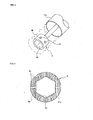
Fig. 3 is a perspective view illustrating a socket arranged in the head portion of the wrench. -
Fig. 4 is a front view showing through holes formed in the socket. -
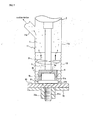
Fig. 5 is a sectional side view showing the wrench sucking the shavings generated at fastening the bolt to the nut. -
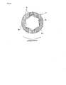
Fig. 6 is a front view showing the other embodiment of the through holes. -
Fig. 7 is a sectional side view showing the other embodiment of the wrench having a fan, provided in the shaft, rotating together with the socket. -
Fig. 8 is a sectional side view showing an impact wrench, in which the rotating axis of the socket is perpendicular to the longitudinal direction of the body. -
Fig. 9 is a bottom view showing an impact wrench, in which the rotating axis of the socket is perpendicular to the longitudinal direction of the body. - The best mode for carrying out the present invention is described below, referring attached drawings.
-
Fig. 1 shows an impact wrench 1 as a fastening tool fastening a fastening member such as a bolt to a fastened member such as a nut, including asocket 6 for gripping the fastening member, abody 2 for supporting thesocket 6 rotatably via a rotatingshaft 5, and agrip 3 extending from thebody 2 for the operator to hold the wrench 1. - The
body 2 has a motor connected to theshaft 5 for driving thesocket 6, and thegrip 3 has a trigger 7 for switching the drive of the motor. - In the wrench 1, the rotating axis of the socket 6 (that is the axis of the shaft 5) is the same as the longitudinal direction (left: and right direction in
Fig. 1 ) of thebody 2. - The outer periphery of the
body 2 is covered with abody cover 11 from the side of the socket 6 (head portion) to the side of the grip 3 (base portion). - As shown in
Fig. 2 , thecover 11 is stuck to thebody 2 at themiddle 11b and thebase end 11c, whereby the sealing is secured between thebody 2 and thecover 11. - The
cover 11 extends the leadingend 11 a from thebody 2 toward thesocket 6, covering the surroundings of theshaft 5 with defming a space C around theshaft 5. - The
cover 11 is opened at the leading end. - The
cover 11 has rigidity to a certain extent in that the cover maintains the shape self-supportingly, and has elasticity to a certain extent in that the sealing is secured between thebody 2 and thecover 11 when stuck to thebody 2, for example the material of thecover 11 is the polyvinyl chloride. - The
end 11a of thecover 11 is connected with asuction cover 12 extending toward thesocket 6 and having a tubular shape at the tip thereof. - The
suction cover 12 has a certain length from theend 11a of thecover 11 to the tip of thesocket 6 or beyond the tip of thesocket 6, thereby the suction cover covering the tip of theshaft 5 and the periphery of thesocket 6. - In the embodiment, the
end 11a of thecover 11 may be extended to the tip of theshaft 5 so that thesuction cover 12 only covers thesocket 6. - Note that the
suction cover 12 has a bellows structure stretching in the axis direction of theshaft 5. - The
end 11a of thecover 11, which is arranged to form the space C around theshaft 5, has asuction port 11d for sucking the atmosphere in the space C. - The
suction port 11d may be connected with the hose communicated with the suction device, thereby being capable of sucking the atmosphere in the space C. - The space C is communicated with the inside surrounded by the
suction cover 12, so that sucking through thesuction port 11 d makes it possible to suck the atmosphere in thecover 12. - As depicted in
Fig. 3 , thesocket 6 has aninternal opening 6a, which is formed in accordance with the bolt head to be engaged with the bolt head, and thesocket 6 supports the bolt head fitted therein. - In this manner, the
socket 6 grips the bolt head and rotates together with it. - The
socket 6 has throughholes 6c at the sides thereof, and the holes communicate the inner side of the opening 6a to theouter side 6b of thesocket 6. Theholes 6c is drilled in the orthogonal direction to the rotating axis of thesocket 6. - As shown in
Fig. 4 , thesocket 6 fastens the hexagon-headed bolt, and the opening 6a is formed in hexagonal shape in response to the shape of thehead 51a of the bolt. - The
holes 6c are formed in each side of the inner wall of the opening 6a, and the formed direction of eachhole 6c is radiated from the rotation center of thesocket 6. - In one embodiment shown in
Fig. 5 , when the door is attached to the body using thebolt 51, thescrew portion 51c of thebolt 51 is inserted into thehinge 60 of the door and thebolt 51 is fastened to thenut 70a of thebody 70, whereby the door is attached to thebody 70 via thehinge 60. - As mentioned above, when fastening the
bolt 51 to thenut 70a, the impact wrench 1 is used to fasten thebolt 51 as follows. - The
opening 6a of thesocket 6 is engaged with thehead 51 a of thebolt 51, and pushing the trigger 7 makes thesocket 6 rotated by the motor in thebody 2. In cooperated with the rotation of thesocket 6, thebolt 51 rotates to be fastened to thenut 70a. - The
hinge 60 is fastened to thebody 70, so that the door is attached to thebody 70. - Note that the door (including the hinge 60) and the body (including the
nut 70a) have electrodepostion coating films. - When the wrench 1 fastens the
bolt 51 and the door is attached to thebody 70 having the coating film, thescrew portion 51c of thebolt 51 shaves the coating film of thenut 70a of thebody 70, and at the same time, theflange 51b provided with thehead 51a of thebolt 51 has a contact with thebody 70, so that the coating film of thebody 70 is shaved off for generating the shavings at the side of thehead 51a of thebolt 51. - If the shavings scatter and adhere to the surfaces of the
body 70 and the door, the poor coating quality such as the seeding occurs when performing the second coating or the finish coating at the coating step, so that the wrench 1 easily collects the shavings generated in fastening thebolt 51 to thenut 70a so as not to scatter around. - When the wrench 1 fastens the
bolt 51 to thenut 70a, theopening 6a of thesocket 6 engages with thehead 51a of thebolt 51 and thesocket 6 is rotated, at the time that thesocket 6 covers thebolt 51, the tip of thecover 12 is contacted to thehinge 60. - Mentioned above, the
suction cover 12 has the certain length from theend 11a of thebody cover 11 to the tip of thesocket 6 or beyond the tip of thesocket 6, so that the tip of thesuction cover 12 contacts to thehinge 60 and thesuction cover 12 covers thehead 51a of thebolt 51 and thesocket 6 engaged with thehead 51a. - When fastening the
bolt 51, the atmosphere surrounding thesocket 6 and the other members is sucked through theport 11d connected with the suction device. - The
socket 6 and the surroundings are covered with thesuction cover 12 and the atmosphere in thesuction cover 12 is sucked when fastening thebolt 51, as a result, the shavings generated at the side of thehead 51a of thebolt 51 is sucked through theport 11d, thereby preventing the scattering around. - In such a case, the
socket 6 has theholes 6c, so that the shavings generated in theopening 6a of thesocket 6 caused by the contact of thesocket 6 to thehead 51a of thebolt 51 are took out of thesocket 6 through theholes 6c and sucked through theport 11d as well as the shavings generated at the periphery of thesocket 6. - The shavings sucked through the
port 11d is collected by the suction device or captured by the filter disposed between theport 11d and the suction device. - The suction device for sucking the atmosphere surrounded by the
suction cover 12 through theport 11d may be employed by a wondergun connected to the air pipes in the factory where the coating step is performed. - The wondergun utilizes the back pressure generated by the air in the air pipes to suck the atmosphere in the
suction cover 12 through the hoses connected to theport 11d. - As described above, the wrench 1 sucks the atmosphere in the
suction cover 12 through thesuction port 11d and collects the shavings generated when fastening thebolt 51, thereby preventing the scattering of the shavings. - Thus, when temporarily attaching the door to the
body 70 at the coating step, it is prevented to occur the poor coating quality such as the seeding caused by adhering of the shavings to thebody 70 or the door, thereby improving the coating quality. - In the embodiment, the
holes 6c of thesocket 6 are, as shown inFig. 4 , formed as radiated from the rotation center of thesocket 6 toward outside, and explained below is the advantageous embodiment of theholes 6c. - For example, as depicted in
Fig. 6 , the formed directions of the holes are inclined by the angle θ to the opposite side to the rotating direction of thesocket 6 with respect to the radiation direction from the center of the rotation axis of thesocket 6. - In other words, in this embodiment, the inner ends of the
holes 6c are shifted toward the rotating direction with respect to the outer end, and theholes 6c direct at the directions inclined gradually from inside to outside by the angle θ to the opposite side to the rotating direction of thesocket 6 with respect to the radiation direction. - In the above-described embodiment, in which the
holes 6c are formed as radiated from the rotation center of thesocket 6 as shown inFig. 4 , the rotating direction of thesocket 6 is perpendicular to the formed directions of theholes 6c, so that there may be the case that the shavings generated in theopening 6a are not removed through theholes 6c and left at the corners of the inside of theopening 6a. - In the advantageous embodiment shown in
Fig. 6 , the formed directions of theholes 6c are inclined to the opposite direction to the rotation direction of thesocket 6, so that the angle which the rotating direction of thesocket 6 and the formed directions of theholes 6c make is smaller than right angle; as a result, it becomes easier for the shavings to enter theholes 6c in accordance with the rotation of thesocket 6, and for the shavings generated in theopening 6a to be discharged through theholes 6c. - Thus, it is prevented to leave the shavings in the
opening 6a of thesocket 6 and the efficient collection of the shavings is provided. - In the preferable embodiment, in order to improve the efficiency for collecting the shavings generated at the fastening of the
bolt 51, the wrench 1 may include a fan for blowing toward theport 11d in the surrounded area with thesuction cover 12. - For example, as depicted in
Fig. 7 , the wrench 1 has afan 31 in theshaft 5, and thefan 31 rotates together with thesocket 6. - The
fan 31 blows toward thebody 2 from thesocket 6 in thesuction cover 12 when thesocket 6 is rotated for fastening thebolt 51, so that the airflow generated by thefan 31 toward theport 11 d strengthens the airflow generated by the suction at theport 11d from thesocket 6 to thebody 2. - Thus, increasing the suction performance in the
suction cover 12 toward theport 11d, the efficiency for collecting the shavings generated at the fastening of thebolt 51 is improved. - In the wrench 1 as above-described embodiment, the direction of the rotating axis of the
socket 6 is the same as the longitudinal direction (left and right direction inFig. 1 ) of thebody 2, andFigs. 8, 9 show the wrench 1 as the other embodiment, in which the rotating axis of thesocket 6 is orthogonal to the longitudinal direction (left and right direction inFigs. 8, 9 ) of thebody 2, being capable of collecting the shavings. - In the wrench 1 as depicted in
Figs. 8, 9 , thebody cover 11 covers the tip of thebody 2, and the tip of thecover 11 is connected to thesuction cover 12 surrounding thesocket 6. Thesuction cover 12 has the bellows structure as the same as shown inFigs. 1,2 . - The shavings generated at fastening the
bolt 51 is collected by being sucked through theport 11 d via the space between thesuction cover 12 arranged at the tip of thecover 11 and thesocket 6 and via the space C defined between thecover 11 and thebody 2. - Note that the
cover 11 is stuck to thebody 2 at the portion positioned closer to the base end than theport 11d, and sucking through theport 11d allows to suck the atmosphere around thesocket 6 covered with thesuction cover 12. - The fastening tool according to the present invention is applicable to the fastening tool for fastening the gripped fastening member to the fastened member, especially to the case that the shavings occur in the fastened member when fastening the fastening member to the fastened member.
Claims (3)
- A fastening tool (1) fastening a fastening member (51) supported by a gripping member (6) to a fastened member (70a), comprising:a cover (12) for covering around the gripping member (6); anda suction port (11d) for sucking an atmosphere surrounded by the cover (12),characterized in thatthe gripping member (6) comprises a through hole (6c) communicating an inner side to an outer side thereof
- The fastening tool (1) according to claim 1,
wherein the gripping member (6) rotates in a direction of fastening the fastening member (51), and
wherein the through hole (6c) is formed in a direction perpendicular to the rotating axis of the gripping member (6) and the formed direction of the hole (6c) is inclined to an opposite side to the rotating direction with respect to a radiating direction from a rotation center of the gripping member (6). - The fastening tool(1) according to claim 1 or 2, further comprising:a fan (31) for generating airflow toward the suction port (11d), arranged in the cover (12).
Applications Claiming Priority (2)
| Application Number | Priority Date | Filing Date | Title |
|---|---|---|---|
| JP2007220437A JP4360432B2 (en) | 2007-08-27 | 2007-08-27 | Fastening tool |
| PCT/JP2008/064796 WO2009028362A1 (en) | 2007-08-27 | 2008-08-20 | Fastening tool |
Publications (3)
| Publication Number | Publication Date |
|---|---|
| EP2184135A1 EP2184135A1 (en) | 2010-05-12 |
| EP2184135A4 EP2184135A4 (en) | 2011-09-21 |
| EP2184135B1 true EP2184135B1 (en) | 2015-02-25 |
Family
ID=40387085
Family Applications (1)
| Application Number | Title | Priority Date | Filing Date |
|---|---|---|---|
| EP08792567.3A Not-in-force EP2184135B1 (en) | 2007-08-27 | 2008-08-20 | Fastening tool |
Country Status (6)
| Country | Link |
|---|---|
| US (1) | US8671803B2 (en) |
| EP (1) | EP2184135B1 (en) |
| JP (1) | JP4360432B2 (en) |
| CN (1) | CN101790439B (en) |
| CA (1) | CA2697503C (en) |
| WO (1) | WO2009028362A1 (en) |
Families Citing this family (4)
| Publication number | Priority date | Publication date | Assignee | Title |
|---|---|---|---|---|
| JP2012045665A (en) * | 2010-08-26 | 2012-03-08 | Toyota Motor Corp | Impact tightening tool |
| SE540840C2 (en) * | 2017-05-16 | 2018-11-27 | Atlas Copco Ind Technique Ab | Power screw driver with screw pick-up feature. |
| JP2024131274A (en) * | 2023-03-15 | 2024-09-30 | 株式会社Subaru | Fastening tool and method for manufacturing fastened item |
| CN117429304A (en) * | 2023-11-16 | 2024-01-23 | 无锡华纳威尔金属制造有限公司 | A battery transfer device |
Family Cites Families (18)
| Publication number | Priority date | Publication date | Assignee | Title |
|---|---|---|---|---|
| NL7601588A (en) * | 1975-02-28 | 1976-08-31 | Lechner Helmut | DEVICE POSSIBLE ON A DRILLING MACHINE OR SIMILAR TOOL FOR COLLECTING, RESPECTIVELY DRAINING MATERIAL LOOSEN WHEN DRILLING. |
| JPS5640529Y2 (en) * | 1977-05-27 | 1981-09-22 | ||
| JPS5683374U (en) * | 1979-11-30 | 1981-07-04 | ||
| JPS5698579U (en) * | 1979-12-27 | 1981-08-04 | ||
| US4593583A (en) * | 1982-10-25 | 1986-06-10 | Hi-Shear Corporation | Torque tool adapted to set a fastener and to secure and retain fastener fragments |
| JPS62114885A (en) * | 1985-11-12 | 1987-05-26 | 三菱電機株式会社 | Thread fastening head |
| DE3612466A1 (en) * | 1986-04-14 | 1987-10-22 | Weg Legrand Gmbh | Screwdriver with at least one compressed-air channel and at least one air intake channel to an axially displaceable guide sleeve for the screwing spindle |
| JPS6360520U (en) * | 1986-10-09 | 1988-04-22 | ||
| US4924732A (en) * | 1987-07-27 | 1990-05-15 | Alliance Automation Systems, Inc. | Power driven screwdriver with vacuum for removing contaminants |
| JPH01138711U (en) * | 1988-03-15 | 1989-09-21 | ||
| JPH0574770U (en) | 1992-03-25 | 1993-10-12 | 本田技研工業株式会社 | Hand tools |
| SG94335A1 (en) * | 1999-10-01 | 2003-02-18 | Ibm | A screw-pick-up apparatus |
| JP2002046075A (en) * | 2000-08-01 | 2002-02-12 | Sumitomo Metal Steel Products Inc | Chip suction device for electric driver |
| US20020154960A1 (en) * | 2001-04-19 | 2002-10-24 | Lin Sheng Chieh | Power drill with vacuum dust-collection ability |
| DE10346207A1 (en) * | 2003-10-06 | 2005-04-28 | Bosch Gmbh Robert | Suction unit for power tool, comprising dust receptacle integrated in suction head |
| JP4607789B2 (en) | 2006-02-16 | 2011-01-05 | 三菱電機株式会社 | Connector, board and portable device |
| DE102006048719A1 (en) * | 2006-10-16 | 2008-04-17 | Robert Bosch Gmbh | System with a hand tool |
| JP2009052679A (en) | 2007-08-27 | 2009-03-12 | Toyota Motor Corp | bolt |
-
2007
- 2007-08-27 JP JP2007220437A patent/JP4360432B2/en not_active Expired - Fee Related
-
2008
- 2008-08-20 US US12/675,332 patent/US8671803B2/en not_active Expired - Fee Related
- 2008-08-20 CN CN2008801046611A patent/CN101790439B/en not_active Expired - Fee Related
- 2008-08-20 CA CA2697503A patent/CA2697503C/en not_active Expired - Fee Related
- 2008-08-20 EP EP08792567.3A patent/EP2184135B1/en not_active Not-in-force
- 2008-08-20 WO PCT/JP2008/064796 patent/WO2009028362A1/en not_active Ceased
Also Published As
| Publication number | Publication date |
|---|---|
| EP2184135A4 (en) | 2011-09-21 |
| CA2697503A1 (en) | 2009-03-05 |
| JP4360432B2 (en) | 2009-11-11 |
| JP2009050966A (en) | 2009-03-12 |
| EP2184135A1 (en) | 2010-05-12 |
| CA2697503C (en) | 2012-12-18 |
| CN101790439A (en) | 2010-07-28 |
| CN101790439B (en) | 2012-02-01 |
| US20100199810A1 (en) | 2010-08-12 |
| WO2009028362A1 (en) | 2009-03-05 |
| US8671803B2 (en) | 2014-03-18 |
Similar Documents
| Publication | Publication Date | Title |
|---|---|---|
| US10603754B2 (en) | Universal-fit vacuum assisted dust collection hood for routers | |
| US8834641B2 (en) | Method of use for debris removal system for power tool | |
| US9387578B2 (en) | Handle arrangement for sander | |
| US8671803B2 (en) | Fastening tool | |
| US20050000052A1 (en) | Vacuum attachment for drilling tool | |
| CN110386095B (en) | Transport device | |
| US8578554B2 (en) | System and method for capturing dust from power tool operation | |
| US20070264092A1 (en) | Dust collector for drill | |
| JP2010036260A (en) | Portable tool | |
| US20120260456A1 (en) | System and method for capturing resultant dust from power tool operation | |
| US20180093372A1 (en) | Paddle assembly on a compact sander | |
| CN102310395B (en) | Impact tool | |
| JP7488077B2 (en) | Fastening Tools | |
| CN110386096A (en) | Transporting equipment | |
| KR101508814B1 (en) | Vacuum tip for Electric screw driver | |
| KR20040084305A (en) | Part painting device of multi-function | |
| CN1990192A (en) | Suction device for a handheld power tool | |
| CN220216948U (en) | Electric cutting tool | |
| JP3043801U (en) | Roof tile cutting equipment | |
| KR20050036369A (en) | Hose assemble for cleaner and upright-type vacuum cleaner having the same | |
| CN121448117A (en) | Structure for attaching component to door inner panel | |
| CN215078055U (en) | Distance measuring devices and sweeping robots | |
| CN117301174A (en) | Cutting mechanism and cutting equipment | |
| KR200357162Y1 (en) | Structure of moter cover combine of a vacuum cleaner | |
| JP2001062772A (en) | Working robot |
Legal Events
| Date | Code | Title | Description |
|---|---|---|---|
| PUAI | Public reference made under article 153(3) epc to a published international application that has entered the european phase |
Free format text: ORIGINAL CODE: 0009012 |
|
| 17P | Request for examination filed |
Effective date: 20100223 |
|
| AK | Designated contracting states |
Kind code of ref document: A1 Designated state(s): AT BE BG CH CY CZ DE DK EE ES FI FR GB GR HR HU IE IS IT LI LT LU LV MC MT NL NO PL PT RO SE SI SK TR |
|
| AX | Request for extension of the european patent |
Extension state: AL BA MK RS |
|
| DAX | Request for extension of the european patent (deleted) | ||
| REG | Reference to a national code |
Ref country code: DE Ref legal event code: R079 Ref document number: 602008036826 Country of ref document: DE Free format text: PREVIOUS MAIN CLASS: B25B0021000000 Ipc: B25B0021020000 |
|
| A4 | Supplementary search report drawn up and despatched |
Effective date: 20110823 |
|
| RIC1 | Information provided on ipc code assigned before grant |
Ipc: B25B 23/00 20060101ALI20110817BHEP Ipc: B25B 21/02 20060101AFI20110817BHEP |
|
| RAP1 | Party data changed (applicant data changed or rights of an application transferred) |
Owner name: TOYOTA JIDOSHA KABUSHIKI KAISHA |
|
| GRAP | Despatch of communication of intention to grant a patent |
Free format text: ORIGINAL CODE: EPIDOSNIGR1 |
|
| INTG | Intention to grant announced |
Effective date: 20140904 |
|
| INTG | Intention to grant announced |
Effective date: 20140910 |
|
| GRAS | Grant fee paid |
Free format text: ORIGINAL CODE: EPIDOSNIGR3 |
|
| GRAA | (expected) grant |
Free format text: ORIGINAL CODE: 0009210 |
|
| AK | Designated contracting states |
Kind code of ref document: B1 Designated state(s): AT BE BG CH CY CZ DE DK EE ES FI FR GB GR HR HU IE IS IT LI LT LU LV MC MT NL NO PL PT RO SE SI SK TR |
|
| REG | Reference to a national code |
Ref country code: GB Ref legal event code: FG4D |
|
| REG | Reference to a national code |
Ref country code: CH Ref legal event code: EP |
|
| REG | Reference to a national code |
Ref country code: IE Ref legal event code: FG4D |
|
| REG | Reference to a national code |
Ref country code: DE Ref legal event code: R096 Ref document number: 602008036826 Country of ref document: DE Effective date: 20150409 |
|
| REG | Reference to a national code |
Ref country code: AT Ref legal event code: REF Ref document number: 711521 Country of ref document: AT Kind code of ref document: T Effective date: 20150415 |
|
| REG | Reference to a national code |
Ref country code: DE Ref legal event code: R084 Ref document number: 602008036826 Country of ref document: DE |
|
| REG | Reference to a national code |
Ref country code: NL Ref legal event code: VDEP Effective date: 20150225 |
|
| REG | Reference to a national code |
Ref country code: AT Ref legal event code: MK05 Ref document number: 711521 Country of ref document: AT Kind code of ref document: T Effective date: 20150225 |
|
| REG | Reference to a national code |
Ref country code: LT Ref legal event code: MG4D |
|
| PG25 | Lapsed in a contracting state [announced via postgrant information from national office to epo] |
Ref country code: HR Free format text: LAPSE BECAUSE OF FAILURE TO SUBMIT A TRANSLATION OF THE DESCRIPTION OR TO PAY THE FEE WITHIN THE PRESCRIBED TIME-LIMIT Effective date: 20150225 Ref country code: LT Free format text: LAPSE BECAUSE OF FAILURE TO SUBMIT A TRANSLATION OF THE DESCRIPTION OR TO PAY THE FEE WITHIN THE PRESCRIBED TIME-LIMIT Effective date: 20150225 Ref country code: ES Free format text: LAPSE BECAUSE OF FAILURE TO SUBMIT A TRANSLATION OF THE DESCRIPTION OR TO PAY THE FEE WITHIN THE PRESCRIBED TIME-LIMIT Effective date: 20150225 Ref country code: NO Free format text: LAPSE BECAUSE OF FAILURE TO SUBMIT A TRANSLATION OF THE DESCRIPTION OR TO PAY THE FEE WITHIN THE PRESCRIBED TIME-LIMIT Effective date: 20150525 Ref country code: SE Free format text: LAPSE BECAUSE OF FAILURE TO SUBMIT A TRANSLATION OF THE DESCRIPTION OR TO PAY THE FEE WITHIN THE PRESCRIBED TIME-LIMIT Effective date: 20150225 Ref country code: FI Free format text: LAPSE BECAUSE OF FAILURE TO SUBMIT A TRANSLATION OF THE DESCRIPTION OR TO PAY THE FEE WITHIN THE PRESCRIBED TIME-LIMIT Effective date: 20150225 |
|
| PG25 | Lapsed in a contracting state [announced via postgrant information from national office to epo] |
Ref country code: LV Free format text: LAPSE BECAUSE OF FAILURE TO SUBMIT A TRANSLATION OF THE DESCRIPTION OR TO PAY THE FEE WITHIN THE PRESCRIBED TIME-LIMIT Effective date: 20150225 Ref country code: AT Free format text: LAPSE BECAUSE OF FAILURE TO SUBMIT A TRANSLATION OF THE DESCRIPTION OR TO PAY THE FEE WITHIN THE PRESCRIBED TIME-LIMIT Effective date: 20150225 Ref country code: GR Free format text: LAPSE BECAUSE OF FAILURE TO SUBMIT A TRANSLATION OF THE DESCRIPTION OR TO PAY THE FEE WITHIN THE PRESCRIBED TIME-LIMIT Effective date: 20150526 Ref country code: IS Free format text: LAPSE BECAUSE OF FAILURE TO SUBMIT A TRANSLATION OF THE DESCRIPTION OR TO PAY THE FEE WITHIN THE PRESCRIBED TIME-LIMIT Effective date: 20150625 |
|
| PG25 | Lapsed in a contracting state [announced via postgrant information from national office to epo] |
Ref country code: NL Free format text: LAPSE BECAUSE OF FAILURE TO SUBMIT A TRANSLATION OF THE DESCRIPTION OR TO PAY THE FEE WITHIN THE PRESCRIBED TIME-LIMIT Effective date: 20150225 |
|
| PG25 | Lapsed in a contracting state [announced via postgrant information from national office to epo] |
Ref country code: RO Free format text: LAPSE BECAUSE OF FAILURE TO SUBMIT A TRANSLATION OF THE DESCRIPTION OR TO PAY THE FEE WITHIN THE PRESCRIBED TIME-LIMIT Effective date: 20150225 Ref country code: SK Free format text: LAPSE BECAUSE OF FAILURE TO SUBMIT A TRANSLATION OF THE DESCRIPTION OR TO PAY THE FEE WITHIN THE PRESCRIBED TIME-LIMIT Effective date: 20150225 Ref country code: EE Free format text: LAPSE BECAUSE OF FAILURE TO SUBMIT A TRANSLATION OF THE DESCRIPTION OR TO PAY THE FEE WITHIN THE PRESCRIBED TIME-LIMIT Effective date: 20150225 Ref country code: DK Free format text: LAPSE BECAUSE OF FAILURE TO SUBMIT A TRANSLATION OF THE DESCRIPTION OR TO PAY THE FEE WITHIN THE PRESCRIBED TIME-LIMIT Effective date: 20150225 Ref country code: CZ Free format text: LAPSE BECAUSE OF FAILURE TO SUBMIT A TRANSLATION OF THE DESCRIPTION OR TO PAY THE FEE WITHIN THE PRESCRIBED TIME-LIMIT Effective date: 20150225 |
|
| REG | Reference to a national code |
Ref country code: DE Ref legal event code: R097 Ref document number: 602008036826 Country of ref document: DE |
|
| PG25 | Lapsed in a contracting state [announced via postgrant information from national office to epo] |
Ref country code: PL Free format text: LAPSE BECAUSE OF FAILURE TO SUBMIT A TRANSLATION OF THE DESCRIPTION OR TO PAY THE FEE WITHIN THE PRESCRIBED TIME-LIMIT Effective date: 20150225 |
|
| PG25 | Lapsed in a contracting state [announced via postgrant information from national office to epo] |
Ref country code: IT Free format text: LAPSE BECAUSE OF FAILURE TO SUBMIT A TRANSLATION OF THE DESCRIPTION OR TO PAY THE FEE WITHIN THE PRESCRIBED TIME-LIMIT Effective date: 20150225 |
|
| PLBE | No opposition filed within time limit |
Free format text: ORIGINAL CODE: 0009261 |
|
| STAA | Information on the status of an ep patent application or granted ep patent |
Free format text: STATUS: NO OPPOSITION FILED WITHIN TIME LIMIT |
|
| 26N | No opposition filed |
Effective date: 20151126 |
|
| PG25 | Lapsed in a contracting state [announced via postgrant information from national office to epo] |
Ref country code: SI Free format text: LAPSE BECAUSE OF FAILURE TO SUBMIT A TRANSLATION OF THE DESCRIPTION OR TO PAY THE FEE WITHIN THE PRESCRIBED TIME-LIMIT Effective date: 20150225 |
|
| PG25 | Lapsed in a contracting state [announced via postgrant information from national office to epo] |
Ref country code: MC Free format text: LAPSE BECAUSE OF FAILURE TO SUBMIT A TRANSLATION OF THE DESCRIPTION OR TO PAY THE FEE WITHIN THE PRESCRIBED TIME-LIMIT Effective date: 20150225 Ref country code: LU Free format text: LAPSE BECAUSE OF FAILURE TO SUBMIT A TRANSLATION OF THE DESCRIPTION OR TO PAY THE FEE WITHIN THE PRESCRIBED TIME-LIMIT Effective date: 20150820 |
|
| REG | Reference to a national code |
Ref country code: CH Ref legal event code: PL |
|
| GBPC | Gb: european patent ceased through non-payment of renewal fee |
Effective date: 20150820 |
|
| PG25 | Lapsed in a contracting state [announced via postgrant information from national office to epo] |
Ref country code: LI Free format text: LAPSE BECAUSE OF NON-PAYMENT OF DUE FEES Effective date: 20150831 Ref country code: CH Free format text: LAPSE BECAUSE OF NON-PAYMENT OF DUE FEES Effective date: 20150831 |
|
| PG25 | Lapsed in a contracting state [announced via postgrant information from national office to epo] |
Ref country code: BE Free format text: LAPSE BECAUSE OF FAILURE TO SUBMIT A TRANSLATION OF THE DESCRIPTION OR TO PAY THE FEE WITHIN THE PRESCRIBED TIME-LIMIT Effective date: 20150225 |
|
| REG | Reference to a national code |
Ref country code: IE Ref legal event code: MM4A |
|
| REG | Reference to a national code |
Ref country code: FR Ref legal event code: ST Effective date: 20160429 |
|
| PG25 | Lapsed in a contracting state [announced via postgrant information from national office to epo] |
Ref country code: GB Free format text: LAPSE BECAUSE OF NON-PAYMENT OF DUE FEES Effective date: 20150820 Ref country code: IE Free format text: LAPSE BECAUSE OF NON-PAYMENT OF DUE FEES Effective date: 20150820 |
|
| PG25 | Lapsed in a contracting state [announced via postgrant information from national office to epo] |
Ref country code: FR Free format text: LAPSE BECAUSE OF NON-PAYMENT OF DUE FEES Effective date: 20150831 |
|
| PG25 | Lapsed in a contracting state [announced via postgrant information from national office to epo] |
Ref country code: MT Free format text: LAPSE BECAUSE OF FAILURE TO SUBMIT A TRANSLATION OF THE DESCRIPTION OR TO PAY THE FEE WITHIN THE PRESCRIBED TIME-LIMIT Effective date: 20150225 |
|
| PG25 | Lapsed in a contracting state [announced via postgrant information from national office to epo] |
Ref country code: HU Free format text: LAPSE BECAUSE OF FAILURE TO SUBMIT A TRANSLATION OF THE DESCRIPTION OR TO PAY THE FEE WITHIN THE PRESCRIBED TIME-LIMIT; INVALID AB INITIO Effective date: 20080820 Ref country code: BG Free format text: LAPSE BECAUSE OF FAILURE TO SUBMIT A TRANSLATION OF THE DESCRIPTION OR TO PAY THE FEE WITHIN THE PRESCRIBED TIME-LIMIT Effective date: 20150225 |
|
| PG25 | Lapsed in a contracting state [announced via postgrant information from national office to epo] |
Ref country code: CY Free format text: LAPSE BECAUSE OF FAILURE TO SUBMIT A TRANSLATION OF THE DESCRIPTION OR TO PAY THE FEE WITHIN THE PRESCRIBED TIME-LIMIT Effective date: 20150225 |
|
| PG25 | Lapsed in a contracting state [announced via postgrant information from national office to epo] |
Ref country code: TR Free format text: LAPSE BECAUSE OF FAILURE TO SUBMIT A TRANSLATION OF THE DESCRIPTION OR TO PAY THE FEE WITHIN THE PRESCRIBED TIME-LIMIT Effective date: 20150225 |
|
| PGFP | Annual fee paid to national office [announced via postgrant information from national office to epo] |
Ref country code: DE Payment date: 20170815 Year of fee payment: 10 |
|
| PG25 | Lapsed in a contracting state [announced via postgrant information from national office to epo] |
Ref country code: PT Free format text: LAPSE BECAUSE OF FAILURE TO SUBMIT A TRANSLATION OF THE DESCRIPTION OR TO PAY THE FEE WITHIN THE PRESCRIBED TIME-LIMIT Effective date: 20150225 |
|
| REG | Reference to a national code |
Ref country code: DE Ref legal event code: R119 Ref document number: 602008036826 Country of ref document: DE |
|
| PG25 | Lapsed in a contracting state [announced via postgrant information from national office to epo] |
Ref country code: DE Free format text: LAPSE BECAUSE OF NON-PAYMENT OF DUE FEES Effective date: 20190301 |