EP2183565B1 - Sensing device arrangement for fuel storage tanks - Google Patents
Sensing device arrangement for fuel storage tanks Download PDFInfo
- Publication number
- EP2183565B1 EP2183565B1 EP07841121.2A EP07841121A EP2183565B1 EP 2183565 B1 EP2183565 B1 EP 2183565B1 EP 07841121 A EP07841121 A EP 07841121A EP 2183565 B1 EP2183565 B1 EP 2183565B1
- Authority
- EP
- European Patent Office
- Prior art keywords
- sensing device
- controller
- sensing
- sensing devices
- devices
- Prior art date
- Legal status (The legal status is an assumption and is not a legal conclusion. Google has not performed a legal analysis and makes no representation as to the accuracy of the status listed.)
- Active
Links
Images

Classifications
-
- G—PHYSICS
- G01—MEASURING; TESTING
- G01M—TESTING STATIC OR DYNAMIC BALANCE OF MACHINES OR STRUCTURES; TESTING OF STRUCTURES OR APPARATUS, NOT OTHERWISE PROVIDED FOR
- G01M3/00—Investigating fluid-tightness of structures
- G01M3/02—Investigating fluid-tightness of structures by using fluid or vacuum
- G01M3/04—Investigating fluid-tightness of structures by using fluid or vacuum by detecting the presence of fluid at the leakage point
- G01M3/16—Investigating fluid-tightness of structures by using fluid or vacuum by detecting the presence of fluid at the leakage point using electric detection means
- G01M3/18—Investigating fluid-tightness of structures by using fluid or vacuum by detecting the presence of fluid at the leakage point using electric detection means for pipes, cables or tubes; for pipe joints or seals; for valves; for welds; for containers, e.g. radiators
- G01M3/186—Investigating fluid-tightness of structures by using fluid or vacuum by detecting the presence of fluid at the leakage point using electric detection means for pipes, cables or tubes; for pipe joints or seals; for valves; for welds; for containers, e.g. radiators for containers, e.g. radiators
-
- B—PERFORMING OPERATIONS; TRANSPORTING
- B67—OPENING, CLOSING OR CLEANING BOTTLES, JARS OR SIMILAR CONTAINERS; LIQUID HANDLING
- B67D—DISPENSING, DELIVERING OR TRANSFERRING LIQUIDS, NOT OTHERWISE PROVIDED FOR
- B67D7/00—Apparatus or devices for transferring liquids from bulk storage containers or reservoirs into vehicles or into portable containers, e.g. for retail sale purposes
- B67D7/04—Apparatus or devices for transferring liquids from bulk storage containers or reservoirs into vehicles or into portable containers, e.g. for retail sale purposes for transferring fuels, lubricants or mixed fuels and lubricants
-
- B—PERFORMING OPERATIONS; TRANSPORTING
- B67—OPENING, CLOSING OR CLEANING BOTTLES, JARS OR SIMILAR CONTAINERS; LIQUID HANDLING
- B67D—DISPENSING, DELIVERING OR TRANSFERRING LIQUIDS, NOT OTHERWISE PROVIDED FOR
- B67D7/00—Apparatus or devices for transferring liquids from bulk storage containers or reservoirs into vehicles or into portable containers, e.g. for retail sale purposes
- B67D7/06—Details or accessories
- B67D7/32—Arrangements of safety or warning devices; Means for preventing unauthorised delivery of liquid
- B67D7/3209—Arrangements of safety or warning devices; Means for preventing unauthorised delivery of liquid relating to spillage or leakage, e.g. spill containments, leak detection
-
- G—PHYSICS
- G01—MEASURING; TESTING
- G01M—TESTING STATIC OR DYNAMIC BALANCE OF MACHINES OR STRUCTURES; TESTING OF STRUCTURES OR APPARATUS, NOT OTHERWISE PROVIDED FOR
- G01M3/00—Investigating fluid-tightness of structures
- G01M3/02—Investigating fluid-tightness of structures by using fluid or vacuum
- G01M3/26—Investigating fluid-tightness of structures by using fluid or vacuum by measuring rate of loss or gain of fluid, e.g. by pressure-responsive devices, by flow detectors
- G01M3/28—Investigating fluid-tightness of structures by using fluid or vacuum by measuring rate of loss or gain of fluid, e.g. by pressure-responsive devices, by flow detectors for pipes, cables or tubes; for pipe joints or seals; for valves ; for welds
- G01M3/2892—Investigating fluid-tightness of structures by using fluid or vacuum by measuring rate of loss or gain of fluid, e.g. by pressure-responsive devices, by flow detectors for pipes, cables or tubes; for pipe joints or seals; for valves ; for welds for underground fuel dispensing systems
Definitions
- This invention relates to detection devices for monitoring hazardous maternal storage and has particular application to the arrangement and controlling of detection devices.
- fluid e.g., liquid or gas
- fluid levels such as fluid level, pressure, temperature, density, etc.
- storage tanks both above ground and underground
- storage tanks may range in size (e.g., 20,000 gallons) and in use, generally contain a stratified fuel sitting atop an inch or two of water.
- sensing devices and systems designed to, for example, measure the fuel level, temperature and/or density within these tanks, which may then be used for fluid volume and tank leak detection calculations.
- sensing devices and systems designed to monitor various parameters around the tanks. As is customary, the sensing devices may be operatively coupled to a central controller that receives signals from the sensing devices indicative of the state of the fuel within the tank and/or parameters surrounding the tank.
- Intrinsic safety barriers are generally devices that limit current, voltage, and total energy delivered to sensing device located in the hazardous area. Limiting the power to the sensing devices helps to prevent or reduce the likelihood of fires and explosions from occurring in areas containing hazardous chemicals, gases, or other ignitable atmospheres. While being necessary or desirable, these barriers add cost and complexity to the installation and set up of sensing device networks used in monitoring the storage tanks and surrounding area. Conventional networks contain sensing devices (e.g., probes, sensors, etc.) that are individually connected to their own dedicated barrier and then to a controller.
- sensing devices e.g., probes, sensors, etc.
- sensing device networks require a significant amount of operator interaction.
- an operator will typically have to manually input various data about each of the sensing devices into the controller.
- This data may include voltages, currents, and various threshold values so that the controller knows how to use the data coming from the sensing device to determine if the sensing device is in alarm.
- a wrong threshold value may render the sensing device inoperable for its intended purpose.
- operator errors may be difficult to detect.
- the installer is required to manually compare the ISB voltage and current parameters to the device's voltage and current parameters, and manually calculate the total capacitance and inductance of all the devices and again compare the total with the maximum safe value for the ISB.
- An error in the calculation of the inductance and capacitance may unintentionally result in potentially putting the sensing device in an unsafe condition, which could remain undetected.
- one objective of the invention is to provide an improved sensing device arrangement that reduces the complexity of connecting sensing devices to a controller, not only in the number of network cable runs, but also in the number of wires within a cable.
- a further objective of the invention is to reduce the amount of operator configuration at the controller after installing a sensing device.
- Another objective of the invention is to ensure that the site is safe to operate by allowing the controller to check the entity parameters of the intrinsic safety barriers and compare them to the connected sensing devices to ensure that the parameters are not exceeded.
- US 5202667 discloses a sensing device arrangement for a fuel storage system including at least one storage tank, a plurality of sensing devices positioned in or around the at least one storage tank, and a controller in electrical communication with the plurality of sensing devices.
- the present invention provides a sensing device arrangement which is characterized in that the controller is configured to communicate with each sensing device of the plurality of sensing devices on a single bi-directional data line, and in that an asynchronous communications protocol is used to transmit data over the single bi-directional data line.
- the sensing devices are configured in a multi-drop configuration.
- a sensing device of the plurality of sensing devices includes an interface component having a microprocessor operable to communicate with the controller, and an active or passive sensing component electrically coupled to the interface component.
- the interface component may be operable to store a unique identifier for the sensing device as well as other device characteristics such as voltage, current, capacitance, inductance, threshold values, manufacturer, manufactured date, and software version.
- Sensing devices of the plurality of sensing devices are activated by the controller.
- Data is acquired by the sensing devices and transmitted to the controller over the single bi-directional data line.
- the controller instructs each sensing device to change to a low power state.
- the data is compared to a threshold value for the sensing device and only transmitted if the threshold is exceeded.
- the data is periodically transmitted from the sensing device to the controller regardless of the threshold value.
- Sensing devices in a sensing device arrangement for a fuel storage system are recognized by the controller over the single bi-directional data line.
- a discovery message is broadcast from the controller to a plurality of sensing devices in electrical communication with the controller over the data line.
- the controller transmits a sync character to the plurality of sensing devices over the data line.
- a sensing device of the plurality of sensing devices transmits its unique identifier to the controller over the data line.
- the controller After receiving the unique identifier, transmits a silencing instruction from the to the sensing device, where the silencing instruction causes the sensing device to ignore further discovery messages and sync characters sent from the controller.
- the controller broadcasts subsequent discovery messages to the plurality of sensing devices along with transmitting a subsequent sync character.
- a subsequent sensing device of the plurality of sensing devices that has not received a silencing instruction transmits its unique identification to the controller over the single bi-directional data line and receives a silencing instruction from the controller.
- the sensing device monitors the single bi-directional data line connecting the plurality of sensing devices to ascertain if another sensing device of the plurality of sensing devices is already transmitting a unique identifier. If there are no transmissions on the single bi-directional data line, the sensing device transmits a first byte of the unique identification of the sensing device to the controller. In one embodiment, the sensing device transmits the byte of data by driving the single bi-directional data line high when transmitting a bit value of one (1) or passively allowing a pull down resistor to pull the single bi-directional data line low when transmitting a bit value of zero (0). The single bi-directional data line is monitored when transmitting the bit value of zero (0).
- the sensing device ignores subsequent sync characters until the controller sends a subsequent broadcast of a discovery message.
- the sensing device receives a subsequent sync character from the controller, and transmits a next byte of data representing the unique identification of the sensing device in response to the sync character.
- the sensing device receives a silencing instruction from the controller to change from an active state to a low power state and ignore further discovery message broadcasts and sync characters from the controller.
- a characteristic of the sensing device is transmitted with the unique identification to the controller.
- Embodiments verify compliance between a sensing device arrangement and an intrinsic safety barrier for a fuel storage system by broadcasting a discovery message over a single bi-directional data line to discover a plurality of sensing devices.
- a controller receives electrical characteristics of the plurality of sensing devices and calculates a characteristic of the sensing device arrangement using the characteristics transmitted by the plurality of sensing devices. Compliance between the sensing device arrangement and the intrinsic safety barrier is verified.
- the controller in response to the characteristic of the sensing device arrangement being out of compliance with the intrinsic safety barrier, the controller shuts down the sensing device arrangement.
- Embodiments of the present invention provide a sensing device arrangement for a fuel storage system having reduced complexity and cost when compared to conventional sensing device arrangements. Aspects of the invention provide for a significant reduction in the amount of cabling and wiring, a reduction in the space requirements for the wiring (e.g, reduced conduit size for carrying wiring), a reduction in the number or intrinsic safety barriers, a reduction in the number of ports in the controller, and other benefits. Such a reduction provides for a less complex sensing device network that assists in reducing time, costs, and labor associated with the installation of such networks. Aspects of the invention further provide for reduced operator interactions, which may in turn provide for a more accurate and reliable sensing device network.
- FIG. 1 is a schematic illustration of a fuel dispensing system 10 that incorporates a conventional controller and sensing device arrangement.
- the fuel dispensing system 10 includes a source of fuel 12 having fuel 14 contained therein.
- the source 12 of fuel may be an underground fuel tank, such as that used at a retail gas station for instance.
- the fuel dispensing system 10 includes a stand pipe extending into the fuel tank, a sump 16, various flow control and flow measurement devices (not shown) and a section of piping 18 that is mechanically and fluidicly coupled to a fuel dispensing unit 20.
- the fuel dispensing unit 20 is mounted on a pedestal 22, which may be made of concrete and which in turn is mounted on a surface, such as, for example, a concrete surface of a retail gas station.
- the fuel dispensing system 10 includes a rigid pipe or conduit 24 that extends upwardly through the interior of the dispensing unit 20.
- Pipe 24 is mechanically coupled and in fluid communication with pipe 18.
- Pipe 24 is also in fluid communication with a flexible hose 26 that terminates in a nozzle 28 that is adapted for dispensing fuel into the fuel tank of a motor vehicle, such as an automobile, truck, etc.
- a controller 30 is operable to monitor a plurality of sensing devices 32, 34a-34h.
- the sensing devices 32, 34a-34h may include devices such as probes, sensors, or other measuring devices.
- sensing device 32 may be a probe for monitoring the fuel level in source 12.
- Such probes may operate on magnetostrictive technology and are commercially available from, for example, OPW Fuel Management Systems (Hodgkins, IL).
- Such probes may further include other devices, such as temperature and density measuring devices and/or other devices for measuring various fluid properties.
- the sensing devices 34a-34h may generally be used to determine conditions around the fuel dispensing system.
- the sensing devices may include temperature devices, hydrocarbon detectors, pressure devices, liquid detection device, density sensors, fluid type sensors (e.g., water, air, or hydrocarbon), and other devices for detecting a leak or monitoring operation of the system.
- each of the sensing devices 32, 34a-34h individually connects to the controller 30 via its own dedicated cabling and port at the controller 30.
- the sensing devices 32, 34 are generally placed in hazardous areas, in and around explosive materials, they are typically supplied power with an Intrinsic Safety Barrier ("ISB").
- ISBs are devices that limit current, voltage, and total energy delivered to sensing devices 32, 34a-34h or other instrumentation located in a hazardous area. Limiting the energy prevents or reduces the likelihood of fires and explosions from occurring in areas with hazardous chemicals, gases, or other ignitable atmospheres. In the conventional configuration illustrated in FIG.
- each sensing device 32, 34a-34h requires not only a separate connection to the controller 30, but also its own ISB, adding both complexity and cost to sensing device installations including both the cost of the ISB and the large amount of cabling and wire for connecting the individual sensing devices to the controller.
- the sensing device network shown in FIG. 1 is costly and time and labor intensive to install, which further increases overall costs. Installations become even more complex and costly as additional sources of fuel are added and connected to a pump. The problem becomes even larger as more pumps are added.
- the limited power environment established by the ISBs has presented challenges for reducing the wiring and complexity of sensing device networks, as well as the time, cost and labor associated with the installation of such networks.
- Embodiments in accordance with the invention present a sensing device arrangement and method to assist in overcoming the challenges with prior conventional arrangements.
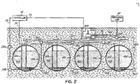
- multiple storage tanks 40a-40d having fuel 42a-42d respectively contained therein, arc mechanically and fluidicly connected through a manifold 44 to a section of piping 46 and on to a dispensing unit 48.
- the sensing device arrangement for such an embodiment requires fewer connections (three shown 52, 54, 56) to a controller 50 and therefore fewer ISBs (e.g. three corresponding to connections 52, 54, 56) connecting the multiple sensing devices 58a-58f, 60a-60d, and 62a-62h.
- the ISB limits the power available to the sensing devices, all of the sensing devices along the connections 52, 54, 56 in FIG. 2 may not be simultaneously fully powered.
- the number of sensing devices that can be feasibly connected together depends on the type of sensing device and its power requirements including electrical characteristics such as inductance and capacitance, plus any further limitations set by the ISBs.
- sensing devices 60a-60d on connection 54 which may be probes monitoring tank levels and possibly fluid temperatures, pressures and/or densities, may be limited to a maximum of about four per ISB connection. As noted above fewer or more probes may be used depending on the power requirements of the probes and/or the limit established by the ISB. The limit allows for power sufficient to activate one probe while the remaining probes are in a low power state.
- the sensing devices 58a-58f and 62a-62g may be sensors that have power requirements different from the probes above (typically less than) allowing for more sensors, e.g., in excess of eight, to be connected together.
- the sensors similar to the probes, would be limited such that the power requirements to have one active sensor with the remaining sensors in a low power state along with a summation of other electrical characteristics such as inductance and capacitance would be less than the maximum allowed by the ISB.
- Other embodiments with other types of probes or sensors may have other limits as to the number of sensing devices that can be connected together. Still other embodiments may be limited as to both the number and types of sensing devices connected together.
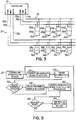
- the sensing devices may be configured in a multi-drop configuration in some embodiments as illustrated in FIG. 3 .
- controller 70 communicates through busses 72 and 74 (e.g., cables) with sensing devices 76a-76d and 82a-82d respectively.
- the bus connection includes three wires, for example wires 72a, 72b, and 72c, to supply power and ground to the sensing devices, as well as a single bi-directional data line for communication between the sensing devices 76a-76d and controller 70.
- Controller 70 uses asynchronous communications to communicate between the sensing devices 76a-76d on the data line 72c.
- Sensing devices 76a-76d and 82a-82d may include an interface component 78a-78d, 84a-84d, which is electrically coupled to an active or passive sensing component 80a-80d, 86a-86d.
- the interface component 78a-78d, 84a-84d may include a microprocessor operable to communicate with the controller 70 and store a unique identifier and sensing device characteristics such as capacitance, inductance, threshold values, manufacturer/manufactured date, software version, etc.
- the sensing devices 76a-76d, 82a-82d maintain a power level sufficient to supply power to the microprocessor in the interface component 78a-78d, 84a-84d such that the microprocessor can be in communication with the controller 70, while the remainder of the sensing device 76a-76d, 82a-82d is powered off or waiting in a dormant or standby condition.
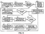
- the controller To avoid data collisions on the single data line, the controller only communicates with one of the sensing devices at a time. In order to communicate, the controller needs to be able to identify each of the sensing devices on the bus. To this end, each sensing device has a unique identification that may be transmitted to the controller over the single bi-directional data line (e.g., 72c, 74c). The controller learns the identity of the sensing devices during a start-up discovery process illustrated in the flowchart in FIG. 4 , as will now be described. In an embodiment, circuitry as is generally known in the art is used on the bus to make the data line low (e.g. about zero volts) or high (e.g. about 5 volts).
- the data line in its dormant state is pulled low by a pull down resistor to ground.
- a sensing device when transmitting data, actively makes the data line high, but when it needs to output a zero, it releases the drive to the data line and allows the pull down resistor to drive the data line low.
- the sensing device may itself briefly drive the data line low to overcome the capacitance in the cable.
- the controller sends a broadcast discovery message to all of the sensing devices on the bus in block 102.
- the controller then sends a sync character to all of the sensing devices in block 104 requesting that the sensors transmit their unique identification. Because the individual sensing devices are not clocked together, the sensing devices may not simultaneously respond to the sync character. If there is a device to respond to the discovery message and sync character ("yes" branch of decision block 106), the sensing device checks the data line to ascertain if another sensing device is already transmitting in block 108.
- the sensing device transmits a unique identifier, e.g. serial number or other identifier, to the controller as a series of bytes composed of bits.
- a unique identifier e.g. serial number or other identifier
- the sensing device drives the data line high.
- the sensing device stops driving the data line high and passively allows the pull down resister to pull the data line low.
- the sensing device monitors the data line in block 116. If the data line is high ("yes" branch of decision block 118), then the sensing device detects another sensing device of the plurality of sensing devices is transmitting.
- the current sensing device then stops transmitting and waits in a low power state, ignoring subsequent sync characters from the controller and waits for the next broadcast of the discovery message in block 112 from the controller. If the data line is low ("no" branch of decision block 118) then the sensing device continues to send data until the sensing device completes the transmission of the unique identifier in block 120, continuing to monitor the data line when sending "0" bits. In other embodiments, other methods of avoiding data collisions may be implemented.
- Each byte of the unique identifier is transmitted in response to a sync character from the controller.
- the sensing device may also transmit other information related to the sensing device during the discovery process as discussed further below.
- the controller After receiving all of the bytes associated with the unique identifier, the controller then sends the unique identifier back out on the data line with a silencing instruction in block 122. Resending the unique identifier operates as a double check that the proper sensing device on the bus is receiving the silencing instruction. The sensing device acknowledges the silencing instruction in block 124 and then ignores any subsequent discovery requests and sync characters sent by the controller.
- the process continues at block 102 as the controller continues to broadcast discovery messages until there are no further responses on the data line ("no" branch of decision block 106).
- the discovery has completed and the controller may verify compliance of the sensing devices on the bus with the ISB as discussed in more detail below.
- the controller is operable to shut down the bus and the sensing devices if the bus and sensing devices exceed the limits of the ISB.
- the controller may resume the discovery sequence by sending a global reset message to all of the devices on the bus.
- Each sensing device contains details of its type and electrical characteristics along with its description, which may be sent to the controller during the discovery process. Additional information, such as voltage, current, inductance, and capacitance levels as well as manufactured date and software version may also be sent to the controller. An operator may additionally add information related to the physical location of the sensing device into the controller. The controller at this point has enough information to process the data from the sensing devices without any operator intervention in addition to verifying proper installation and compliance with the ISB.
- Each sensing device has certain entity parameters (e.g. voltage, current, inductance and capacitance) that must match the entity parameters of the ISB for the safe operation of a gas station, for example.
- entity parameters e.g. voltage, current, inductance and capacitance
- the inductance values and capacitance values of each or the sensing devices is summed and added to the inductance value and capacitance value of the connecting cable by the installer to calculate values for the sensing device arrangement. The installer would then compare the sensing device arrangement values to the limits established by the ISB.
- the process becomes more automated, eliminating the potential error introduced by operator input and manual calculations to verify that the site is safe.
- the controller has access to the ISB parameters and the ability to total and check the sensing device parameters against the ISB, thus allowing it refuse to run if an unsafe condition exists.
- Threshold values may also be programmed into the sensing devices so that the controller is only sent information when one of its threshold values is exceeded, which may assist in reducing traffic on the data line. To ensure that the data that is stored in the controller is relatively current, in some embodiments, the sensing devices will periodically send sensor data even if the threshold value has not been exceeded.
- the flowchart in FIG. 5 illustrates a process that the controller may use to acquire data from the sensing devices.
- the controller begins by polling the sensing devices on the bus in block 130.
- the sensing devices are individually powered on, while others remain in a low power state, such as a dormant mode or a sleep mode. For example, in the low power state, all of the interface components of the sensing devices may be communicating with the controller while the sensor components are off/powered down.
- the controller then instructs one of the sensing devices to activate in block 132.
- the sensing device acquires data in block 134, and may, in some embodiments, transmit the data directly to the controller.
- the acquired data is checked against a threshold value of the sensing device and if the data value exceeds the threshold ("yes" branch of decision block 136), the data is transmitted to the controller in block 138.
- the unique identifier may also accompany the data transmission. As discussed above, transmitting data only when a threshold is exceeded may assist in reducing data traffic on the data line.
- the controller then instructs the sensing device to deactivate, returning the sensing device to its low power state in block 140. If another sensing device is connected to the bus and has not acquired data (“yes" branch of decision block 142), then the process continues with the next sensing device at block 132. If all sensing devices have been polled ("no" branch of decision block 142), the controller ends the polling of the devices in block 144.
- the sensing device arrangement overcomes the challenges of prior arrangements by configuring sensing devices in a multi-drop configuration, thereby reducing the number of ports and ISBs required to connect the sensing devices to the controller, and lowering the overall costs of the system.
- the arrangement also reduces the amount of wiring necessary as fewer cables are needed to connect the sensing devices to the controller, further lowering the cost and reducing the complexity of the installation.
- each cable includes only three wires as opposed to conventional cables having a four wire arrangement. Thus, conduit sizes may be correspondingly reduced. Automatic detection of the sensing devices removes or reduces costs associated with installation and reduces potential sources of error from the sensing device arrangement by reducing the tasks associated with an operator.
Landscapes
- Physics & Mathematics (AREA)
- General Physics & Mathematics (AREA)
- Engineering & Computer Science (AREA)
- Mechanical Engineering (AREA)
- Arrangements For Transmission Of Measured Signals (AREA)
Priority Applications (1)
| Application Number | Priority Date | Filing Date | Title |
|---|---|---|---|
| PL07841121T PL2183565T3 (pl) | 2007-08-20 | 2007-08-20 | Układ urządzenia wykrywającego do zbiorników do składowania paliwa |
Applications Claiming Priority (1)
| Application Number | Priority Date | Filing Date | Title |
|---|---|---|---|
| PCT/US2007/076327 WO2009025666A1 (en) | 2007-08-20 | 2007-08-20 | Sensing device arrangement for fuel storage tanks |
Publications (2)
| Publication Number | Publication Date |
|---|---|
| EP2183565A1 EP2183565A1 (en) | 2010-05-12 |
| EP2183565B1 true EP2183565B1 (en) | 2017-10-25 |
Family
ID=39357249
Family Applications (1)
| Application Number | Title | Priority Date | Filing Date |
|---|---|---|---|
| EP07841121.2A Active EP2183565B1 (en) | 2007-08-20 | 2007-08-20 | Sensing device arrangement for fuel storage tanks |
Country Status (4)
| Country | Link |
|---|---|
| EP (1) | EP2183565B1 (pl) |
| CN (1) | CN101842681B (pl) |
| PL (1) | PL2183565T3 (pl) |
| WO (1) | WO2009025666A1 (pl) |
Families Citing this family (4)
| Publication number | Priority date | Publication date | Assignee | Title |
|---|---|---|---|---|
| US8281655B2 (en) | 2009-04-03 | 2012-10-09 | Eaton Corporation | Fuel gauging system utilizing a digital fuel gauging probe |
| US8682600B2 (en) * | 2011-07-06 | 2014-03-25 | Saudi Arabian Oil Company | Pipeline leak detection and location system through pressure and cathodic protection soil |
| CN112919397B (zh) * | 2014-08-11 | 2023-04-21 | 富兰克林加油系统公司 | 燃料管理系统、安装系统和验证燃料系统安装的方法 |
| US20210139233A1 (en) * | 2019-11-07 | 2021-05-13 | Veeder-Root Company | Fuel dispensing environment having wireless sensing arrangement |
Family Cites Families (7)
| Publication number | Priority date | Publication date | Assignee | Title |
|---|---|---|---|---|
| US1676A (en) | 1840-07-10 | Improvement in the mode of | ||
| US4835521A (en) * | 1987-11-05 | 1989-05-30 | Emhart Industries, Inc. | Fluid status detector |
| US5223826A (en) * | 1988-08-26 | 1993-06-29 | Nakamura Kiki Engineering Co., Ltd. | Control/supervisory signal transmission system |
| DE3921744A1 (de) * | 1989-07-01 | 1991-01-03 | Bayerische Motoren Werke Ag | Kommunikationsverfahren fuer einen einleitungs-datenbus von kraftfahrzeugen |
| US5008653A (en) * | 1989-12-22 | 1991-04-16 | Emhart Industries, Inc. | Fluid detector with overfill probe |
| US5202667A (en) | 1990-10-19 | 1993-04-13 | Monitoring Systems, Inc. | Electric leakage detector for underground storage tank systems |
| USH1676H (en) * | 1994-03-03 | 1997-09-02 | Shell Oil Company | Site management system for containing hazardous spills and leaks |
-
2007
- 2007-08-20 PL PL07841121T patent/PL2183565T3/pl unknown
- 2007-08-20 WO PCT/US2007/076327 patent/WO2009025666A1/en not_active Ceased
- 2007-08-20 EP EP07841121.2A patent/EP2183565B1/en active Active
- 2007-08-20 CN CN200780101055XA patent/CN101842681B/zh active Active
Non-Patent Citations (1)
| Title |
|---|
| None * |
Also Published As
| Publication number | Publication date |
|---|---|
| CN101842681B (zh) | 2012-11-07 |
| WO2009025666A1 (en) | 2009-02-26 |
| CN101842681A (zh) | 2010-09-22 |
| EP2183565A1 (en) | 2010-05-12 |
| HK1144109A1 (en) | 2011-01-28 |
| PL2183565T3 (pl) | 2018-04-30 |
Similar Documents
| Publication | Publication Date | Title |
|---|---|---|
| US7825816B2 (en) | Sensing device arrangement for fuel storage tanks | |
| US10196258B2 (en) | Method and system for mobile distribution station | |
| US10087065B2 (en) | Mobile distribution station having sensor communication lines routed with hoses | |
| US10289126B2 (en) | Mobile distribution station with guided wave radar fuel level sensors | |
| US20260078753A1 (en) | Mobile distribution station with fail-safes | |
| US7671482B2 (en) | Hydrogen powered vehicle refueling strategy | |
| EP2183565B1 (en) | Sensing device arrangement for fuel storage tanks | |
| KR101662050B1 (ko) | 누출 감지 장치 및 이를 포함하는 누출 감지 시스템 | |
| CN101999100A (zh) | 用于传递安置在危险位置中的系统元件的传感器信息的系统、装置和方法 | |
| KR101403644B1 (ko) | 토양, 지하수 오염방지 배송관 누출 감지 시스템 및 그 방법 | |
| WO2015022517A1 (en) | Monitoring system for liquid transfer and method | |
| US20140125496A1 (en) | Universal Remote Display System | |
| KR101103311B1 (ko) | 단열 이중 관 손상감지 시스템 | |
| EP1934564A1 (en) | Tank gauging system | |
| CN108980637A (zh) | 一种管道渗漏监测系统及监测方法 | |
| US20070157705A1 (en) | Leak detection system with addressable sensors | |
| RU2443986C2 (ru) | Компоновка датчика для резервуаров-хранилищ топлива | |
| JP3070590B2 (ja) | エンジン発電設備 | |
| HK1144109B (en) | Sensing device arrangement for fuel storage tanks | |
| JP2018060524A (ja) | フィールド保守ツールにおける接続確認 | |
| KR101883809B1 (ko) | 복합 감지 장치, 이를 이용한 시설물 관리 장치 및 시스템 | |
| RU2215676C1 (ru) | Система хранения нефти | |
| CN114777031B (zh) | 油气管路监测设备 | |
| KR20150135799A (ko) | Plc 콘트롤러부를 이용한 히트 트레이싱부 온도 정보 모니터링 시스템 | |
| CA3023080C (en) | Method and system for mobile distribution station |
Legal Events
| Date | Code | Title | Description |
|---|---|---|---|
| PUAI | Public reference made under article 153(3) epc to a published international application that has entered the european phase |
Free format text: ORIGINAL CODE: 0009012 |
|
| 17P | Request for examination filed |
Effective date: 20100318 |
|
| AK | Designated contracting states |
Kind code of ref document: A1 Designated state(s): AT BE BG CH CY CZ DE DK EE ES FI FR GB GR HU IE IS IT LI LT LU LV MC MT NL PL PT RO SE SI SK TR |
|
| AX | Request for extension of the european patent |
Extension state: AL BA HR MK RS |
|
| DAX | Request for extension of the european patent (deleted) | ||
| 17Q | First examination report despatched |
Effective date: 20101222 |
|
| RAP1 | Party data changed (applicant data changed or rights of an application transferred) |
Owner name: OPW FUEL MANAGEMENT SYSTEMS, INC. |
|
| GRAP | Despatch of communication of intention to grant a patent |
Free format text: ORIGINAL CODE: EPIDOSNIGR1 |
|
| INTG | Intention to grant announced |
Effective date: 20170502 |
|
| GRAS | Grant fee paid |
Free format text: ORIGINAL CODE: EPIDOSNIGR3 |
|
| GRAA | (expected) grant |
Free format text: ORIGINAL CODE: 0009210 |
|
| AK | Designated contracting states |
Kind code of ref document: B1 Designated state(s): AT BE BG CH CY CZ DE DK EE ES FI FR GB GR HU IE IS IT LI LT LU LV MC MT NL PL PT RO SE SI SK TR |
|
| REG | Reference to a national code |
Ref country code: GB Ref legal event code: FG4D |
|
| REG | Reference to a national code |
Ref country code: CH Ref legal event code: EP |
|
| REG | Reference to a national code |
Ref country code: AT Ref legal event code: REF Ref document number: 940361 Country of ref document: AT Kind code of ref document: T Effective date: 20171115 |
|
| REG | Reference to a national code |
Ref country code: IE Ref legal event code: FG4D |
|
| REG | Reference to a national code |
Ref country code: DE Ref legal event code: R096 Ref document number: 602007052825 Country of ref document: DE |
|
| REG | Reference to a national code |
Ref country code: NL Ref legal event code: MP Effective date: 20171025 |
|
| REG | Reference to a national code |
Ref country code: LT Ref legal event code: MG4D |
|
| REG | Reference to a national code |
Ref country code: AT Ref legal event code: MK05 Ref document number: 940361 Country of ref document: AT Kind code of ref document: T Effective date: 20171025 |
|
| PG25 | Lapsed in a contracting state [announced via postgrant information from national office to epo] |
Ref country code: NL Free format text: LAPSE BECAUSE OF FAILURE TO SUBMIT A TRANSLATION OF THE DESCRIPTION OR TO PAY THE FEE WITHIN THE PRESCRIBED TIME-LIMIT Effective date: 20171025 |
|
| PG25 | Lapsed in a contracting state [announced via postgrant information from national office to epo] |
Ref country code: LT Free format text: LAPSE BECAUSE OF FAILURE TO SUBMIT A TRANSLATION OF THE DESCRIPTION OR TO PAY THE FEE WITHIN THE PRESCRIBED TIME-LIMIT Effective date: 20171025 Ref country code: FI Free format text: LAPSE BECAUSE OF FAILURE TO SUBMIT A TRANSLATION OF THE DESCRIPTION OR TO PAY THE FEE WITHIN THE PRESCRIBED TIME-LIMIT Effective date: 20171025 Ref country code: ES Free format text: LAPSE BECAUSE OF FAILURE TO SUBMIT A TRANSLATION OF THE DESCRIPTION OR TO PAY THE FEE WITHIN THE PRESCRIBED TIME-LIMIT Effective date: 20171025 Ref country code: SE Free format text: LAPSE BECAUSE OF FAILURE TO SUBMIT A TRANSLATION OF THE DESCRIPTION OR TO PAY THE FEE WITHIN THE PRESCRIBED TIME-LIMIT Effective date: 20171025 |
|
| PG25 | Lapsed in a contracting state [announced via postgrant information from national office to epo] |
Ref country code: GR Free format text: LAPSE BECAUSE OF FAILURE TO SUBMIT A TRANSLATION OF THE DESCRIPTION OR TO PAY THE FEE WITHIN THE PRESCRIBED TIME-LIMIT Effective date: 20180126 Ref country code: LV Free format text: LAPSE BECAUSE OF FAILURE TO SUBMIT A TRANSLATION OF THE DESCRIPTION OR TO PAY THE FEE WITHIN THE PRESCRIBED TIME-LIMIT Effective date: 20171025 Ref country code: AT Free format text: LAPSE BECAUSE OF FAILURE TO SUBMIT A TRANSLATION OF THE DESCRIPTION OR TO PAY THE FEE WITHIN THE PRESCRIBED TIME-LIMIT Effective date: 20171025 Ref country code: IS Free format text: LAPSE BECAUSE OF FAILURE TO SUBMIT A TRANSLATION OF THE DESCRIPTION OR TO PAY THE FEE WITHIN THE PRESCRIBED TIME-LIMIT Effective date: 20180225 Ref country code: BG Free format text: LAPSE BECAUSE OF FAILURE TO SUBMIT A TRANSLATION OF THE DESCRIPTION OR TO PAY THE FEE WITHIN THE PRESCRIBED TIME-LIMIT Effective date: 20180125 |
|
| REG | Reference to a national code |
Ref country code: DE Ref legal event code: R097 Ref document number: 602007052825 Country of ref document: DE |
|
| PG25 | Lapsed in a contracting state [announced via postgrant information from national office to epo] |
Ref country code: CZ Free format text: LAPSE BECAUSE OF FAILURE TO SUBMIT A TRANSLATION OF THE DESCRIPTION OR TO PAY THE FEE WITHIN THE PRESCRIBED TIME-LIMIT Effective date: 20171025 Ref country code: CY Free format text: LAPSE BECAUSE OF FAILURE TO SUBMIT A TRANSLATION OF THE DESCRIPTION OR TO PAY THE FEE WITHIN THE PRESCRIBED TIME-LIMIT Effective date: 20171025 Ref country code: SK Free format text: LAPSE BECAUSE OF FAILURE TO SUBMIT A TRANSLATION OF THE DESCRIPTION OR TO PAY THE FEE WITHIN THE PRESCRIBED TIME-LIMIT Effective date: 20171025 Ref country code: EE Free format text: LAPSE BECAUSE OF FAILURE TO SUBMIT A TRANSLATION OF THE DESCRIPTION OR TO PAY THE FEE WITHIN THE PRESCRIBED TIME-LIMIT Effective date: 20171025 Ref country code: DK Free format text: LAPSE BECAUSE OF FAILURE TO SUBMIT A TRANSLATION OF THE DESCRIPTION OR TO PAY THE FEE WITHIN THE PRESCRIBED TIME-LIMIT Effective date: 20171025 |
|
| REG | Reference to a national code |
Ref country code: FR Ref legal event code: PLFP Year of fee payment: 12 |
|
| PG25 | Lapsed in a contracting state [announced via postgrant information from national office to epo] |
Ref country code: RO Free format text: LAPSE BECAUSE OF FAILURE TO SUBMIT A TRANSLATION OF THE DESCRIPTION OR TO PAY THE FEE WITHIN THE PRESCRIBED TIME-LIMIT Effective date: 20171025 Ref country code: IT Free format text: LAPSE BECAUSE OF FAILURE TO SUBMIT A TRANSLATION OF THE DESCRIPTION OR TO PAY THE FEE WITHIN THE PRESCRIBED TIME-LIMIT Effective date: 20171025 |
|
| PLBE | No opposition filed within time limit |
Free format text: ORIGINAL CODE: 0009261 |
|
| STAA | Information on the status of an ep patent application or granted ep patent |
Free format text: STATUS: NO OPPOSITION FILED WITHIN TIME LIMIT |
|
| 26N | No opposition filed |
Effective date: 20180726 |
|
| PG25 | Lapsed in a contracting state [announced via postgrant information from national office to epo] |
Ref country code: SI Free format text: LAPSE BECAUSE OF FAILURE TO SUBMIT A TRANSLATION OF THE DESCRIPTION OR TO PAY THE FEE WITHIN THE PRESCRIBED TIME-LIMIT Effective date: 20171025 |
|
| REG | Reference to a national code |
Ref country code: DE Ref legal event code: R119 Ref document number: 602007052825 Country of ref document: DE |
|
| PG25 | Lapsed in a contracting state [announced via postgrant information from national office to epo] |
Ref country code: MC Free format text: LAPSE BECAUSE OF FAILURE TO SUBMIT A TRANSLATION OF THE DESCRIPTION OR TO PAY THE FEE WITHIN THE PRESCRIBED TIME-LIMIT Effective date: 20171025 |
|
| REG | Reference to a national code |
Ref country code: CH Ref legal event code: PL |
|
| PG25 | Lapsed in a contracting state [announced via postgrant information from national office to epo] |
Ref country code: LI Free format text: LAPSE BECAUSE OF NON-PAYMENT OF DUE FEES Effective date: 20180831 Ref country code: LU Free format text: LAPSE BECAUSE OF NON-PAYMENT OF DUE FEES Effective date: 20180820 Ref country code: CH Free format text: LAPSE BECAUSE OF NON-PAYMENT OF DUE FEES Effective date: 20180831 |
|
| REG | Reference to a national code |
Ref country code: BE Ref legal event code: MM Effective date: 20180831 |
|
| REG | Reference to a national code |
Ref country code: IE Ref legal event code: MM4A |
|
| PG25 | Lapsed in a contracting state [announced via postgrant information from national office to epo] |
Ref country code: IE Free format text: LAPSE BECAUSE OF NON-PAYMENT OF DUE FEES Effective date: 20180820 Ref country code: DE Free format text: LAPSE BECAUSE OF NON-PAYMENT OF DUE FEES Effective date: 20190301 |
|
| PG25 | Lapsed in a contracting state [announced via postgrant information from national office to epo] |
Ref country code: BE Free format text: LAPSE BECAUSE OF NON-PAYMENT OF DUE FEES Effective date: 20180831 |
|
| PG25 | Lapsed in a contracting state [announced via postgrant information from national office to epo] |
Ref country code: MT Free format text: LAPSE BECAUSE OF NON-PAYMENT OF DUE FEES Effective date: 20180820 |
|
| PG25 | Lapsed in a contracting state [announced via postgrant information from national office to epo] |
Ref country code: TR Free format text: LAPSE BECAUSE OF FAILURE TO SUBMIT A TRANSLATION OF THE DESCRIPTION OR TO PAY THE FEE WITHIN THE PRESCRIBED TIME-LIMIT Effective date: 20171025 |
|
| PG25 | Lapsed in a contracting state [announced via postgrant information from national office to epo] |
Ref country code: HU Free format text: LAPSE BECAUSE OF FAILURE TO SUBMIT A TRANSLATION OF THE DESCRIPTION OR TO PAY THE FEE WITHIN THE PRESCRIBED TIME-LIMIT; INVALID AB INITIO Effective date: 20070820 Ref country code: PT Free format text: LAPSE BECAUSE OF FAILURE TO SUBMIT A TRANSLATION OF THE DESCRIPTION OR TO PAY THE FEE WITHIN THE PRESCRIBED TIME-LIMIT Effective date: 20171025 |
|
| PGFP | Annual fee paid to national office [announced via postgrant information from national office to epo] |
Ref country code: PL Payment date: 20220720 Year of fee payment: 16 |
|
| P01 | Opt-out of the competence of the unified patent court (upc) registered |
Effective date: 20230529 |
|
| PG25 | Lapsed in a contracting state [announced via postgrant information from national office to epo] |
Ref country code: PL Free format text: LAPSE BECAUSE OF NON-PAYMENT OF DUE FEES Effective date: 20230820 |
|
| PG25 | Lapsed in a contracting state [announced via postgrant information from national office to epo] |
Ref country code: PL Free format text: LAPSE BECAUSE OF NON-PAYMENT OF DUE FEES Effective date: 20230820 |
|
| PGFP | Annual fee paid to national office [announced via postgrant information from national office to epo] |
Ref country code: GB Payment date: 20250826 Year of fee payment: 19 |
|
| PGFP | Annual fee paid to national office [announced via postgrant information from national office to epo] |
Ref country code: FR Payment date: 20250825 Year of fee payment: 19 |