EP2183158B1 - High speed automated filling of solid pharmaceutical product packaging via a conveyor system - Google Patents
High speed automated filling of solid pharmaceutical product packaging via a conveyor system Download PDFInfo
- Publication number
- EP2183158B1 EP2183158B1 EP08797613.0A EP08797613A EP2183158B1 EP 2183158 B1 EP2183158 B1 EP 2183158B1 EP 08797613 A EP08797613 A EP 08797613A EP 2183158 B1 EP2183158 B1 EP 2183158B1
- Authority
- EP
- European Patent Office
- Prior art keywords
- product package
- cavities
- filling
- array
- shuttle
- Prior art date
- Legal status (The legal status is an assumption and is not a legal conclusion. Google has not performed a legal analysis and makes no representation as to the accuracy of the status listed.)
- Active
Links
Images



Classifications
-
- B—PERFORMING OPERATIONS; TRANSPORTING
- B65—CONVEYING; PACKING; STORING; HANDLING THIN OR FILAMENTARY MATERIAL
- B65B—MACHINES, APPARATUS OR DEVICES FOR, OR METHODS OF, PACKAGING ARTICLES OR MATERIALS; UNPACKING
- B65B35/00—Supplying, feeding, arranging or orientating articles to be packaged
- B65B35/30—Arranging and feeding articles in groups
- B65B35/40—Arranging and feeding articles in groups by reciprocating or oscillatory pushers
-
- B—PERFORMING OPERATIONS; TRANSPORTING
- B65—CONVEYING; PACKING; STORING; HANDLING THIN OR FILAMENTARY MATERIAL
- B65B—MACHINES, APPARATUS OR DEVICES FOR, OR METHODS OF, PACKAGING ARTICLES OR MATERIALS; UNPACKING
- B65B5/00—Packaging individual articles in containers or receptacles, e.g. bags, sacks, boxes, cartons, cans, jars
- B65B5/10—Filling containers or receptacles progressively or in stages by introducing successive articles, or layers of articles
- B65B5/101—Filling containers or receptacles progressively or in stages by introducing successive articles, or layers of articles by gravity
- B65B5/103—Filling containers or receptacles progressively or in stages by introducing successive articles, or layers of articles by gravity for packaging pills or tablets
-
- B—PERFORMING OPERATIONS; TRANSPORTING
- B65—CONVEYING; PACKING; STORING; HANDLING THIN OR FILAMENTARY MATERIAL
- B65B—MACHINES, APPARATUS OR DEVICES FOR, OR METHODS OF, PACKAGING ARTICLES OR MATERIALS; UNPACKING
- B65B35/00—Supplying, feeding, arranging or orientating articles to be packaged
- B65B35/06—Separating single articles from loose masses of articles
Definitions
- the present invention relates generally to the field of automated solid pharmaceutical packaging systems. More specifically, the present invention is directed to a unique arrangement of automated solid pharmaceutical packaging machinery which advantageously achieves extremely high throughput for automatically filling solid pharmaceutical product packaging.
- the systems and methods of the present invention are particularly suitable for filling of individualized solid pharmaceutical product packages which may be used to provide a plurality of prescription medications for an individual.
- US 4,834,264 A discloses an apparatus for dispensing solid objects such as, for example, pills or tablets, from a bulk supply into a receptacle containing individual doses of such medication.
- US 7,185,476 B1 describes a fully automated pharmaceutical product packaging machine capable of selectively depositing one or more different solid pharmaceutical products into an individual cavity for each of a plurality of individual patient product package cavities.
- US 2007/0084150 A1 discusses an automated pharmaceutical product packaging machine configured to simultaneously fill a plurality of product package templates in parallel with desired pharmaceutical dosing requirements.
- the present invention is directed to new and improved solid pharmaceutical product packaging solutions which provide a dramatic increase in the overall throughput for the solid pharmaceutical product packaging machine while also minimizing the potential for cross-contamination of the processing machinery arising out of the processing of multiple types of solid pharmaceutical products.
- a method of filling an array of product package cavities with solid pharmaceutical products as defined in claim 1.
- Embodiments of the present invention are defined in the dependent claims.
- Systems used in the method of the present invention for providing individualized solid pharmaceutical product packaging solutions utilize a plurality of filling stations preferably arranged proximate to a conveyor system. Those skilled in the art will appreciate that for uses outside the claimed invention the conveyor system may not be necessary, however, and the unique filling station described herein may be utilized independently.
- Each of the filling stations may be embodied as a version of a conventional flood fill type mechanism wherein a hopper is used to store a large number of a single type of solid pharmaceutical products.
- each of the filling stations is able to incorporate at least one package template or temporary storage portion or shuttle member having a plurality of product package cavity locations corresponding to each of the product package cavities that are to be filled by the system.
- the hopper is used as a source of medications for filling the product package cavities of the product package template or shuttle member.
- a sweeper mechanism or mechanical vibration may be used to ensure that each of the template cavities or cavities of the shuttle member are filled by the solid pharmaceuticals contained within the hopper.
- the temporary storage cavity arrangement of the template or shuttle is used to temporarily secure solid pharmaceutical products that are received from the hopper of the filling station.
- a temporary cover plate may be shifted so that openings in the temporary cover do not correspond with locations of openings in the bottom of the hopper and therefore no additional medications from the hopper will pass through openings in the bottom thereof when the temporary storage template or shuttle member is withdrawn from its initial position directly beneath the hopper.
- the product package template or shuttle member is preferably positioned directly beneath a digital camera or other imaging device for automated vision verification that all desired cavities have been filled by the appropriate medications.
- the shuttle or product package template is thereafter preferably moved to a location directly above a conveyor system which preferably transfers either an additional product package template or solid pharmaceutical product package having an array of cavities.
- a conveyor system which preferably transfers either an additional product package template or solid pharmaceutical product package having an array of cavities.
- a transition bock may be utilized to alter the spacing and/or arrangement of the solid pharmaceuticals contained in the array of cavities of the shuttle or initial product package template so that they may be transferred to a further product package template or array having different physical relationships for cavities in its array.
- the transition block simply alters the cavity array spacing from a first spacing for the initial shuttle or temporary storage package cavity to a further spacing for an alternate arrangement.
- a microprocessor controller is programmed to ensure that each of the necessary medications for every single one of one or more prescriptions for a given patient are incorporated into a single customized solid pharmaceutical product package. This is accomplished by ensuring that the package or template associated with a given patient is transferred to locations beneath each filling station corresponding to all of the medications required by the patient's one or more prescriptions:
- the transfer of the medications from the initial temporary storage product package template or shuttle is accomplished by a sliding gate.
- a sliding gate reveals openings so that the desired members from the array are transferred from the shuttle or product package template preferably through the transition block into the further temper storage member or package cavity.
- the sliding gate may be a single member having a size corresponding to the entire array of cavities for the product package template or shuttle member.
- a plurality of gates is provided which are arranged corresponding to either the rows or columns of the array of solid pharmaceutical products found in the initial temporary storage member or product package template.
- the system is able to selectively transfer a limited number of medications which may correspond to the daily doses for an entire week required for a given patient.
- the systems of the prior art were only capable of transferring an entire arrays worth of the solid pharmaceutical products and there was no mechanism for selectively transferring only medications for a given row or column of the array.
- the system then seals the solid pharmaceuticals in the package cavities and preferably prints information identifying the patient and prescriptions on the package.
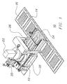
- Figure 1 illustrates, to provide context for the understanding of the invention, a system which is shown generally at 10.
- Figure 1 specifically illustrates the overall arrangement of the various portions of the system.
- only one filling station 12 is illustrated so that the details thereof may be more apparent.
- the filling station 12 extends over a portion of the conveyor system 14.
- the conveyor system 14 is programmed to transfer product package templates 16 or the cavity portion of a solid pharmaceutical product package having an array of cavities.
- Each filling station 12 is preferably comprised of a hopper 20 which contains a bulk supply of a single type of solid pharmaceutical products that are to be deposited in a solid pharmaceutical product package.
- a sweeping mechanism 22 or agitator is utilized to ensure that solid pharmaceutical products contained within the hopper 20 are transferred into the cavities of a shuttle member or temporary storage product package template.
- Figure 1 illustrates an arrangement of the overall device wherein the shuttle member 24 having a plurality of temporary storage cavities 26 is partially extended from an original position beneath the hopper 20.
- a sliding gate is initially positioned between the bulk solid pharmaceutical product contained within the hopper 20 and the shuttle members 24. The sliding gate is provided in order to enable the selective transfer of solid pharmaceutical products from a hopper into the cavities 26 of the shuttle member 24 or product package template.
- the initial gate is placed in the closed position to cover openings in the bottom of the hopper 20 which would otherwise expose cavities 26. This enables the cavities 26 to be filled with the desired solid pharmaceutical products and also prevents solid pharmaceuticals from inadvertently escaping from the hopper 20.
- the shuttle member 24 having solid pharmaceutical products contained within its cavities 26 is then maneuvered to a position beneath a camera member 28. After the temporary storage cavities are removed from their initial location beneath the hopper, the product package template or shuttle member is preferably positioned directly beneath a digital camera or other imaging device for automated vision verification that all desired cavities have been filled by the appropriate medications. This stage of the process is illustrated in Figure 1
- the shuttle or product package template is thereafter preferably moved to a location directly above a conveyor system which preferably transfers the solid pharmaceutical products from the initial shuttle or product package template to either an additional product package template 14 or solid pharmaceutical product package having an array of cavities.
- a conveyor system which preferably transfers the solid pharmaceutical products from the initial shuttle or product package template to either an additional product package template 14 or solid pharmaceutical product package having an array of cavities.
- FIG 2A illustrates, to provide context for the understanding of the invention, a top view of the shuttle tray 30 having a single gate 32 which is a unitary body that slides from an open position wherein the cavities of the shuttle are exposed to a closed position Wherein the cavities are secured by the gate thereby preventing the transfer of solid pharmaceutical products contained within the shuttle tray 30.
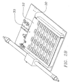
- Figure 2B is a bottom view of the shuttle tray which illustrates the sliding gate 32 and its corresponding actuator 33.
- Figure 3A illustrates a top view of the shuttle tray 30 suitable for use with the invention and haying a multiple gate structure which are plurality of independently moving bodies that slide from an open position wherein the cavities of the shuttle are exposed to a closed position wherein the cavities are secured by the gate thereby preventing the transfer of solid pharmaceutical products contained within the shuttle tray 30.
- Figure 3B is a bottom view of the shuttle tray 30 which illustrates the multiple sliding gate structure wherein individual independent sliding gates 35, 36, 37, and 38 and corresponding independent gate actuators 41, 42, 43, 44 are provided to independently open and close the shuttle cavities secured by the corresponding linear gate members.
- the plurality of gates are arranged corresponding to either the rows or columns of the array of solid pharmaceutical products found in the initial temporary storage member or product package template and is corresponding rows or columns of the package to be filled.
- the system is able to selectively transfer a limited number of medications which may correspond to the daily doses for an entire week required for a given patient.
- the systems of the prior art were only capable of transferring an entire arrays worth of the solid pharmaceutical products and there was no mechanism for selectively transferring only medications for a given row or column of the array.
- FIG 4A is a detailed illustration which shows the shuttle tray 30 in an extended position along with its corresponding gate 32 which in this illustration is a single gate structure.
- the shuttle tray 30 is transferred with its corresponding gate 32 along guide members 51, 52.
- Pneumatic drives may be provided to effect motion of the shuttle tray 30.
- alternative drives may be utilized such as, for example, electric drives or motor drives and/or solenoid. It may be preferable to use solenoid for temporary displacement of the gate members but the particular selection for the drive mechanism is not critical.
- Figure 4A also illustrates the shuttle tray 31 as it is positioned directly above transition block 55.
- a transition bock is a mechanical structure which may be utilized to alter the spacing and/or arrangement of the solid pharmaceuticals contained in the array of cavities of the shuttle or initial product package template so that they may be transferred to a further product package template or array having different physical relationships for cavities in its array. More specifically, the transition block 55 may simply alter the cavity array spacing from a first spacing for the initial shuttle or temporary storage package cavity to a further spacing for an alternate arrangement.
- transition block 55 By using a transition block 55, it is possible to conveniently fill product packages having various cavity arrangements without having to change much of the physical structures associated with individual filling stations.
- the transition block 55 is a convenient mechanism for altering any differences in the physical arrangements for the array members which may exist between an actual product package cavity and the shuttle tray or initial temporary product package template. Accordingly, the systems and methods utilizing the structure are much more flexible and simple to use.
- Figure 4B illustrates an alternate arrangement wherein the shuttle tray 30 is located adjacent to the transition block 55.
- Figure 5A is a cutaway illustration which shows the transition block and its structures for effecting any necessary transition in the arrangement of the cavities.
- Figure 5B is a semi transparent illustration of the transition block 55 illustrated in Figure 5A .
- Figure 5B clearly demonstrates how different arrangements of the cavities in any upper array may be matched to a lower array having a different arrangement of the cavities.
- Figure 6 illustrates a conveyor system 71 for use in conjunction with the filling stations which are example five by triangular blocks 72 in the illustration of Figure 6 .
- the filling stations are used to transfer medications from the individual filling station 72 into independently transferable solid pharmaceutical product package templates 75 or conveyed structures which secure at least a portion of a product package having an array of cavities arranged therein.
- the independent motion of the product package templates 75 or bodies holding at least portions of product package cavities which include arrays of the cavities can be used to quickly and conveniently fill a plurality of prescriptions for a given patient into a blister card package for a given patient having a plurality of different prescriptions. This is accomplished by programming the system to selectively convey independently movable product package templates or bodies holding at least portions of product package cavities beneath filling stations for each of the medications required by a patient's prescriptions.
- transition blocks may be provided at each of the filling stations as necessary to provide the desired flexibility to handle virtually any solid pharmaceutical product package arrangement.
Landscapes
- Engineering & Computer Science (AREA)
- Mechanical Engineering (AREA)
- Medical Preparation Storing Or Oral Administration Devices (AREA)
- Auxiliary Devices For And Details Of Packaging Control (AREA)
- Basic Packing Technique (AREA)
- Containers And Plastic Fillers For Packaging (AREA)
- Supply Of Fluid Materials To The Packaging Location (AREA)
Description
- The present invention relates generally to the field of automated solid pharmaceutical packaging systems. More specifically, the present invention is directed to a unique arrangement of automated solid pharmaceutical packaging machinery which advantageously achieves extremely high throughput for automatically filling solid pharmaceutical product packaging. The systems and methods of the present invention are particularly suitable for filling of individualized solid pharmaceutical product packages which may be used to provide a plurality of prescription medications for an individual.
- A wide variety of solid pharmaceutical product packaging machinery is currently available. Significantly, however, existing arrangements of solid pharmaceutical packaging machinery have issues relating to the potential for cross-contamination of the machinery due to the fact that multiple different medications may be processed via a single structure and therefore particles or portions from one medication may inadvertently and undesirably contaminate the processing machinery which is used in processing another medication. Furthermore, there is an ever increasing demand for individualized solid pharmaceutical product packaging solutions and accordingly higher throughput and capacity is desired for existing machinery.
- The number of patients currently living in managed-care environments is growing dramatically and the rate of growth is expected to increase dramatically in the coming years. Yet another factor related to the increased demand for individualized solid pharmaceutical product packaging solutions is due to the fact that ever-increasing numbers of an aging population are relying upon greater numbers of medications which must be taken daily or in some cases several times in one day. It may be difficult for an individual to meet the dosing requirements for a number of medications in a given day when the medications are provided in bulk containers. Members of an aging population can become confused and may forget whether they have already taken a particular medication. Customized packaging solutions are currently available which provide the consumers with time and date dosing indications but it is necessary for the managed care facility to provide customized packaging of multiple solid pharmaceuticals depending upon the prescriptions required for an individual.
- Accordingly, in light of these considerations, it is apparent that there is an ever increasing demand for individualized solid pharmaceutical product packaging solutions. It is also desirable to provide higher throughput in order to satisfy the greater demand while minimizing the potential for cross-contamination.
-
US 4,834,264 A discloses an apparatus for dispensing solid objects such as, for example, pills or tablets, from a bulk supply into a receptacle containing individual doses of such medication. -
US 7,185,476 B1 describes a fully automated pharmaceutical product packaging machine capable of selectively depositing one or more different solid pharmaceutical products into an individual cavity for each of a plurality of individual patient product package cavities. -
US 2007/0084150 A1 discusses an automated pharmaceutical product packaging machine configured to simultaneously fill a plurality of product package templates in parallel with desired pharmaceutical dosing requirements. - The applicants of the instant invention have discovered new and improved arrangements and highly efficient automated solid pharmaceutical product packaging solutions which are capable of attaining tremendous throughput for packaging individualized groupings of solid pharmaceutical products while also minimizing the potential for cross-contamination of the system.
- The present invention is directed to new and improved solid pharmaceutical product packaging solutions which provide a dramatic increase in the overall throughput for the solid pharmaceutical product packaging machine while also minimizing the potential for cross-contamination of the processing machinery arising out of the processing of multiple types of solid pharmaceutical products. In accordance with the present invention, there is disclosed a method of filling an array of product package cavities with solid pharmaceutical products as defined in claim 1. Embodiments of the present invention are defined in the dependent claims. Systems used in the method of the present invention for providing individualized solid pharmaceutical product packaging solutions utilize a plurality of filling stations preferably arranged proximate to a conveyor system. Those skilled in the art will appreciate that for uses outside the claimed invention the conveyor system may not be necessary, however, and the unique filling station described herein may be utilized independently. Each of the filling stations may be embodied as a version of a conventional flood fill type mechanism wherein a hopper is used to store a large number of a single type of solid pharmaceutical products.
- In accordance with the present invention, each of the filling stations is able to incorporate at least one package template or temporary storage portion or shuttle member having a plurality of product package cavity locations corresponding to each of the product package cavities that are to be filled by the system. The hopper is used as a source of medications for filling the product package cavities of the product package template or shuttle member. A sweeper mechanism or mechanical vibration may be used to ensure that each of the template cavities or cavities of the shuttle member are filled by the solid pharmaceuticals contained within the hopper.
- The temporary storage cavity arrangement of the template or shuttle is used to temporarily secure solid pharmaceutical products that are received from the hopper of the filling station. As soon as the initial product package template or shuttle is filled by the system, a temporary cover plate may be shifted so that openings in the temporary cover do not correspond with locations of openings in the bottom of the hopper and therefore no additional medications from the hopper will pass through openings in the bottom thereof when the temporary storage template or shuttle member is withdrawn from its initial position directly beneath the hopper.
- After the temporary storage cavities are removed their initial location beneath the hopper, the product package template or shuttle member is preferably positioned directly beneath a digital camera or other imaging device for automated vision verification that all desired cavities have been filled by the appropriate medications.
- In accordance with an embodiment, after all of the desired pills have been verified to be present by the imaging system, the shuttle or product package template is thereafter preferably moved to a location directly above a conveyor system which preferably transfers either an additional product package template or solid pharmaceutical product package having an array of cavities. Those skilled in the art will also appreciate that the imaging verification may alternately take place directly over the location of the conveyor system.
- In accordance with an embodiment of the present invention, a transition bock may be utilized to alter the spacing and/or arrangement of the solid pharmaceuticals contained in the array of cavities of the shuttle or initial product package template so that they may be transferred to a further product package template or array having different physical relationships for cavities in its array. In the embodiment, the transition block simply alters the cavity array spacing from a first spacing for the initial shuttle or temporary storage package cavity to a further spacing for an alternate arrangement.
- The conveyor system is then utilized to transfer either a solid pharmaceutical product package portion into which a plurality of solid pharmaceuticals have been positioned via the first filling station to a location beneath one or more additional filling stations so that a desired number of different medications may be provided by the system. In accordance with the system, a microprocessor controller is programmed to ensure that each of the necessary medications for every single one of one or more prescriptions for a given patient are incorporated into a single customized solid pharmaceutical product package. This is accomplished by ensuring that the package or template associated with a given patient is transferred to locations beneath each filling station corresponding to all of the medications required by the patient's one or more prescriptions:
- In accordance with an embodiment of the present invention, the transfer of the medications from the initial temporary storage product package template or shuttle is accomplished by a sliding gate. A sliding gate reveals openings so that the desired members from the array are transferred from the shuttle or product package template preferably through the transition block into the further temper storage member or package cavity. The sliding gate may be a single member having a size corresponding to the entire array of cavities for the product package template or shuttle member. In accordance with the present invention however, a plurality of gates is provided which are arranged corresponding to either the rows or columns of the array of solid pharmaceutical products found in the initial temporary storage member or product package template.
- Advantageously, by providing gates corresponding to the rows or columns of the initial temporary storage template or shuttle, the system is able to selectively transfer a limited number of medications which may correspond to the daily doses for an entire week required for a given patient. The systems of the prior art were only capable of transferring an entire arrays worth of the solid pharmaceutical products and there was no mechanism for selectively transferring only medications for a given row or column of the array.
- In accordance with the preferred exemplary embodiment of the present invention, after all of the necessary solid pharmaceuticals have been deposited into the array of cavities for a temporary storage product package template or shuttle member or the actual package cavities, the system then seals the solid pharmaceuticals in the package cavities and preferably prints information identifying the patient and prescriptions on the package.
-
-
Figure 1 illustrates an arrangement of a system for use with the present invention; -
Figure 2A illustrates a shuttle tray with a single gate; -
Figure 2B illustrates the bottom of the shuttle tray with a single gate; -
Figure 3A illustrates an exemplary shuttle tray with multiple gates for use with the present invention; -
Figure 3B illustrates the bottom of the exemplary shuttle tray with multiple gates for use with the present invention; -
Figure 4A illustrates a shuttle tray or package template positioned over a transition bock for use in an optional method step of the present invention; -
Figure 4B illustrates a shuttle tray or package template positioned adjacent a transition bock for use in an optional method step of the present invention; -
Figure 5A illustrates cutaway details of a transition block for use in an optional method step of the present invention; -
Figure 5B is a semitransparent perspective view illustrating a transition block for use in an optional method step of the present invention; and -
Figure 6 illustrates an exemplary overall conveyor system and an arrangement of filling stations along the conveyor system for use with the present invention. -
Figure 1 illustrates, to provide context for the understanding of the invention, a system which is shown generally at 10.Figure 1 specifically illustrates the overall arrangement of the various portions of the system. In this illustration, only one filling station 12 is illustrated so that the details thereof may be more apparent. In this illustration of the system, the filling station 12 extends over a portion of the conveyor system 14. The conveyor system 14 is programmed to transfer product package templates 16 or the cavity portion of a solid pharmaceutical product package having an array of cavities. - Each filling station 12 is preferably comprised of a hopper 20 which contains a bulk supply of a single type of solid pharmaceutical products that are to be deposited in a solid pharmaceutical product package. A sweeping mechanism 22 or agitator is utilized to ensure that solid pharmaceutical products contained within the hopper 20 are transferred into the cavities of a shuttle member or temporary storage product package template.
Figure 1 illustrates an arrangement of the overall device wherein the shuttle member 24 having a plurality of temporary storage cavities 26 is partially extended from an original position beneath the hopper 20. A sliding gate is initially positioned between the bulk solid pharmaceutical product contained within the hopper 20 and the shuttle members 24. The sliding gate is provided in order to enable the selective transfer of solid pharmaceutical products from a hopper into the cavities 26 of the shuttle member 24 or product package template. - After the cavities 26 of the shuttle member 24 or the product package template have been filled, the initial gate is placed in the closed position to cover openings in the bottom of the hopper 20 which would otherwise expose cavities 26. This enables the cavities 26 to be filled with the desired solid pharmaceutical products and also prevents solid pharmaceuticals from inadvertently escaping from the hopper 20. The shuttle member 24 having solid pharmaceutical products contained within its cavities 26 is then maneuvered to a position beneath a camera member 28. After the temporary storage cavities are removed from their initial location beneath the hopper, the product package template or shuttle member is preferably positioned directly beneath a digital camera or other imaging device for automated vision verification that all desired cavities have been filled by the appropriate medications. This stage of the process is illustrated in
Figure 1 - After all of the desired pills have been verified to be present by the imaging system, the shuttle or product package template is thereafter preferably moved to a location directly above a conveyor system which preferably transfers the solid pharmaceutical products from the initial shuttle or product package template to either an additional product package template 14 or solid pharmaceutical product package having an array of cavities. Those skilled in the art will also appreciate that the imaging verification may alternately take place directly over the location of the conveyor system.
-
Figure 2A illustrates, to provide context for the understanding of the invention, a top view of theshuttle tray 30 having asingle gate 32 which is a unitary body that slides from an open position wherein the cavities of the shuttle are exposed to a closed position Wherein the cavities are secured by the gate thereby preventing the transfer of solid pharmaceutical products contained within theshuttle tray 30.Figure 2B is a bottom view of the shuttle tray which illustrates the slidinggate 32 and its correspondingactuator 33.Figure 3A illustrates a top view of theshuttle tray 30 suitable for use with the invention and haying a multiple gate structure which are plurality of independently moving bodies that slide from an open position wherein the cavities of the shuttle are exposed to a closed position wherein the cavities are secured by the gate thereby preventing the transfer of solid pharmaceutical products contained within theshuttle tray 30.Figure 3B is a bottom view of theshuttle tray 30 which illustrates the multiple sliding gate structure wherein individual independent slidinggates independent gate actuators - In accordance with the invention, the plurality of gates are arranged corresponding to either the rows or columns of the array of solid pharmaceutical products found in the initial temporary storage member or product package template and is corresponding rows or columns of the package to be filled.
- Advantageously, by providing independent gates corresponding to the rows or columns of the initial temporary storage template or shuttle and the package to be filled, the system is able to selectively transfer a limited number of medications which may correspond to the daily doses for an entire week required for a given patient. The systems of the prior art were only capable of transferring an entire arrays worth of the solid pharmaceutical products and there was no mechanism for selectively transferring only medications for a given row or column of the array.
-
Figure 4A is a detailed illustration which shows theshuttle tray 30 in an extended position along with its correspondinggate 32 which in this illustration is a single gate structure. Theshuttle tray 30 is transferred with its correspondinggate 32 alongguide members shuttle tray 30. Those skilled in the art will appreciate that alternative drives may be utilized such as, for example, electric drives or motor drives and/or solenoid. It may be preferable to use solenoid for temporary displacement of the gate members but the particular selection for the drive mechanism is not critical. -
Figure 4A also illustrates the shuttle tray 31 as it is positioned directly abovetransition block 55. A transition bock is a mechanical structure which may be utilized to alter the spacing and/or arrangement of the solid pharmaceuticals contained in the array of cavities of the shuttle or initial product package template so that they may be transferred to a further product package template or array having different physical relationships for cavities in its array. More specifically, thetransition block 55 may simply alter the cavity array spacing from a first spacing for the initial shuttle or temporary storage package cavity to a further spacing for an alternate arrangement. - By using a
transition block 55, it is possible to conveniently fill product packages having various cavity arrangements without having to change much of the physical structures associated with individual filling stations. Thetransition block 55 is a convenient mechanism for altering any differences in the physical arrangements for the array members which may exist between an actual product package cavity and the shuttle tray or initial temporary product package template. Accordingly, the systems and methods utilizing the structure are much more flexible and simple to use.Figure 4B illustrates an alternate arrangement wherein theshuttle tray 30 is located adjacent to thetransition block 55. -
Figure 5A is a cutaway illustration which shows the transition block and its structures for effecting any necessary transition in the arrangement of the cavities. Those skilled in the art will appreciate that by providinginternal transition channels 61 betweenupper openings 62 andlower openings 63 which connect correspondingupper openings 62 withlower openings 63, a wide variety of differences in the arrangement of the cavity arrays between an upper arrangement and a lower arrangement may be accommodated.Figure 5B is a semi transparent illustration of thetransition block 55 illustrated inFigure 5A .Figure 5B clearly demonstrates how different arrangements of the cavities in any upper array may be matched to a lower array having a different arrangement of the cavities. -
Figure 6 illustrates aconveyor system 71 for use in conjunction with the filling stations which are example five bytriangular blocks 72 in the illustration ofFigure 6 . As shown in the illustration ofFigure 6 , the filling stations are used to transfer medications from theindividual filling station 72 into independently transferable solid pharmaceuticalproduct package templates 75 or conveyed structures which secure at least a portion of a product package having an array of cavities arranged therein. Those skilled in the art will appreciate that the independent motion of theproduct package templates 75 or bodies holding at least portions of product package cavities which include arrays of the cavities can be used to quickly and conveniently fill a plurality of prescriptions for a given patient into a blister card package for a given patient having a plurality of different prescriptions. This is accomplished by programming the system to selectively convey independently movable product package templates or bodies holding at least portions of product package cavities beneath filling stations for each of the medications required by a patient's prescriptions. - As noted above, transition blocks may be provided at each of the filling stations as necessary to provide the desired flexibility to handle virtually any solid pharmaceutical product package arrangement.
Claims (6)
- A method of filling an array of product package cavities with solid pharmaceuticals comprising:providing a system (10) comprising a plurality of solid pharmaceutical filling stations (12) arranged adjacent to a conveyor system (14), wherein the system is programmed to selectively convey independently movable product package template shuttles or package portions (24) beneath filling stations (12) for a first medication required by a patient's prescriptions;transferring, via the conveyor system (14), the product package template shuttles or package portions (24) to locations beneath additional filling stations (12) corresponding to each further medication required by the patient's prescription until each of the necessary medications for each and every one of one or more prescriptions for a given patient are deposited into the product package template shuttles or package portions (24);selectively filling at least one row or column of the cavities (26) of a product package template shuttle (24) or package portion with solid pharmaceutical product at each filling station (12) to which the conveyor system (14) automatically transfers the product package template shuttles (24) or package portions;automatically positioning the product package template shuttle or package portions (24) above a further product package template shuttle or a product package portion (16) transferred by a conveying system (14);and providing a plurality of gates (35, 36, 37, 38), each gate corresponding to either rows or columns of said cavities (26) and independently actuatable to open and close to thereby selectively release the solid pharmaceutical products from at least one row or column of cavities (26) of the product package template shuttle (24) into corresponding cavities of the further product package template or product package portion (16) that is transferred by said conveying system (14).
- The method of filling an array of product package cavities according to claim 1, further comprising passing the solid pharmaceuticals through a transition block (55).
- The method according to claim 2 wherein the transition block (55) provides for simultaneous transfer of the solid pharmaceuticals from the product package template shuttle (24) which has a plurality of cavities (26) arranged in an array having a first spacing to the further product package template or product package portion (16) which has an array of cavities arranged at an further different spacing.
- The method of filling an array of product package cavities according to claim 1, further comprising providing automated visual verification that all of the desired cavities have been filled by the required solid pharmaceutical product with an imaging device (24).
- The method of filling an array of product package cavities according to claim 1, further comprising providing a gate (32), corresponding to each row of cavities of the product package template shuttle, beneath each product package template shuttle (24).
- The method of filling an array of product package cavities according to claim 1, further comprising providing an image verification system for processing digital image information and confirming that solid pharmaceuticals corresponding to a patient prescription have been properly transferred from at least one filling station (12) to a plurality of cavity locations corresponding to a patient prescription.
Applications Claiming Priority (2)
| Application Number | Priority Date | Filing Date | Title |
|---|---|---|---|
| US11/838,106 US7784244B2 (en) | 2007-08-13 | 2007-08-13 | High speed automated filling of solid pharmaceutical product packaging via a conveyor system |
| PCT/US2008/072794 WO2009023632A1 (en) | 2007-08-13 | 2008-08-11 | High speed automated filling of solid pharmaceutical product packaging via a conveyor system |
Publications (3)
| Publication Number | Publication Date |
|---|---|
| EP2183158A1 EP2183158A1 (en) | 2010-05-12 |
| EP2183158A4 EP2183158A4 (en) | 2011-08-31 |
| EP2183158B1 true EP2183158B1 (en) | 2016-04-13 |
Family
ID=40351108
Family Applications (1)
| Application Number | Title | Priority Date | Filing Date |
|---|---|---|---|
| EP08797613.0A Active EP2183158B1 (en) | 2007-08-13 | 2008-08-11 | High speed automated filling of solid pharmaceutical product packaging via a conveyor system |
Country Status (8)
| Country | Link |
|---|---|
| US (2) | US7784244B2 (en) |
| EP (1) | EP2183158B1 (en) |
| JP (2) | JP5411859B2 (en) |
| KR (1) | KR101592041B1 (en) |
| AU (1) | AU2008286955B2 (en) |
| CA (1) | CA2695578C (en) |
| ES (1) | ES2574631T3 (en) |
| WO (1) | WO2009023632A1 (en) |
Families Citing this family (37)
| Publication number | Priority date | Publication date | Assignee | Title |
|---|---|---|---|---|
| US7185476B1 (en) * | 1999-05-11 | 2007-03-06 | Mts, Medication Technologies, Inc. | Automated solid pharmaceutical product packaging machine |
| JP5012806B2 (en) * | 2006-09-20 | 2012-08-29 | 株式会社湯山製作所 | Drug packaging device |
| US11264124B2 (en) | 2008-02-20 | 2022-03-01 | Chudy Group, LLC | System and apparatus for item management |
| US8380346B2 (en) * | 2008-02-20 | 2013-02-19 | Chundy Group, LLC | System and apparatus for item management |
| US7958701B2 (en) * | 2008-06-27 | 2011-06-14 | Qem, Inc. | Pill dispenser with interchangeable platen having electronically readable identification |
| US7908827B2 (en) * | 2008-06-27 | 2011-03-22 | Qem, Inc. | Method and apparatus for automatically filling prescriptions using interchangeable platens |
| US8863480B2 (en) * | 2008-06-27 | 2014-10-21 | Qem, Inc. | Pill dispenser with interchangeable platen having electronically readable/writable identification |
| US20110113727A1 (en) * | 2009-11-18 | 2011-05-19 | Bonner Kevin B | Custom Prepackaging Method and Apparatus |
| WO2011109861A1 (en) * | 2010-03-11 | 2011-09-15 | Manrex Pty. Ltd. | Blister sheet loading apparatus with bounce prevention means |
| US20120126554A1 (en) * | 2010-06-10 | 2012-05-24 | Pioneer Hi-Bred International, Inc. | Apparatus, method and system for simultaneously picking up and releasing objects in bulk |
| WO2012054866A2 (en) * | 2010-10-22 | 2012-04-26 | Pcas Patient Care Automation Services Inc. | Apparatus and method for concurrent item dispensing |
| JP5870931B2 (en) * | 2010-11-26 | 2016-03-01 | 株式会社湯山製作所 | Tablet packaging device and tablet packaging method |
| WO2013009852A1 (en) | 2011-07-11 | 2013-01-17 | Omnicare, Inc. | Methods and apparatus for filling packagings with medications |
| US9073206B2 (en) | 2012-06-21 | 2015-07-07 | Omnicare, Inc. | Methods and apparatus for automated filling of packagings with medications |
| DE202012005898U1 (en) * | 2012-06-16 | 2012-07-09 | Harro Höfliger Verpackungsmaschinen GmbH | Dosing disc and capsule filling device with dosing disc |
| CN103771066A (en) * | 2012-10-17 | 2014-05-07 | Jvm有限公司 | Dispensing box for drug-containing ampoule |
| KR102000296B1 (en) * | 2012-10-17 | 2019-07-15 | (주)제이브이엠 | Dispensing box for ampoule-shaped drug |
| EP2754615B1 (en) * | 2013-01-14 | 2015-07-29 | Edwin Kohl | System for personalised filling of blister packs with medications according to specified prescription data |
| EP2754614B1 (en) * | 2013-01-14 | 2015-06-24 | Edwin Kohl | System and method for personalised filling of blister packages with drugs |
| US9477816B2 (en) * | 2013-03-14 | 2016-10-25 | Arxium, Inc. | Pharmaceutical tray filling system and method |
| PT2815984T (en) * | 2013-06-20 | 2016-08-05 | Carefusion Germany 326 Gmbh | Transport device for an automated medication dosing device |
| ES2626779T3 (en) * | 2014-09-08 | 2017-07-26 | Edwin Kohl | Installation and procedure for repackaging different medicines from their respective original blisters to filling blisters |
| CA2939591C (en) * | 2015-08-25 | 2021-11-09 | Chudy Group, LLC | Plural-mode automatic medicament packaging system |
| JP6630518B2 (en) * | 2015-09-04 | 2020-01-15 | 株式会社松尾製作所 | Unwrapping system |
| DE102016219871A1 (en) * | 2016-10-12 | 2018-04-12 | Melvin Haas | System for feeding, sorting and / or palletizing parts |
| KR20180105804A (en) * | 2017-03-16 | 2018-10-01 | (주)제이브이엠 | Blister Packing Device and Packing Method for Blister Pack |
| KR102666501B1 (en) * | 2018-03-09 | 2024-05-17 | 가부시키가이샤 유야마 세이사쿠쇼 | tablet distribution device |
| CN109018564B (en) * | 2018-09-13 | 2020-12-25 | 湖北工业大学 | Cartridge clip type single-row capacitor disc loading device and disc loading method thereof |
| WO2021202835A1 (en) * | 2020-04-01 | 2021-10-07 | Rxsafe Llc | Automatic packager for medications |
| NL2025568B1 (en) * | 2020-05-12 | 2021-11-25 | Vmi Holland Bv | Docking station and method for loading a medicine transport plate |
| US11814203B2 (en) | 2021-02-19 | 2023-11-14 | Altria Client Services Llc | Apparatuses and methods for loading containers with products |
| US12521315B2 (en) | 2021-06-22 | 2026-01-13 | Vmi Holland B.V. | Method, computer program product and dispensing device for dispensing discrete medicaments |
| US11273103B1 (en) | 2021-06-22 | 2022-03-15 | Vmi Holland B.V. | Method, computer program product and dispensing device for dispensing discrete medicaments |
| US11673700B2 (en) | 2021-06-22 | 2023-06-13 | Vmi Holland B.V. | Device and methods for packaging medicaments with fault detection |
| US11498761B1 (en) | 2021-06-22 | 2022-11-15 | Vmi Holland B.V. | Method for dispensing discrete medicaments, a test station for testing a feeder unit, and a method for determining a fill level of a feeder unit |
| CN114652000B (en) * | 2022-04-07 | 2023-03-21 | 烟台工程职业技术学院(烟台市技师学院) | Material delivery device and method for food processing |
| WO2025151583A1 (en) * | 2024-01-12 | 2025-07-17 | Parata Systems, Llc | Methods, systems, and computer program product for generating dispense settings and a cell layout configuration for a drug product packaging system based on drug product characteristics |
Citations (2)
| Publication number | Priority date | Publication date | Assignee | Title |
|---|---|---|---|---|
| US7185476B1 (en) * | 1999-05-11 | 2007-03-06 | Mts, Medication Technologies, Inc. | Automated solid pharmaceutical product packaging machine |
| US20070084150A1 (en) * | 2000-11-01 | 2007-04-19 | Medical Technology Systems, Inc. | Automated solid pharmaceutical product packaging machine |
Family Cites Families (17)
| Publication number | Priority date | Publication date | Assignee | Title |
|---|---|---|---|---|
| US3545164A (en) * | 1968-08-22 | 1970-12-08 | Warnaco Inc | Apparatus and method for filling packaging receptacles |
| US4065000A (en) * | 1976-06-03 | 1977-12-27 | Gary Murton | Pharmaceutical tablet and capsule counter |
| US4101284A (en) * | 1977-10-25 | 1978-07-18 | Abbott Laboratories | Multiple bead dispenser for diagnostic assay |
| FR2427257A1 (en) * | 1978-05-29 | 1979-12-28 | Expandet Sa | DISTRIBUTOR MACHINE FOR PLACING STORED OBJECTS ON DISPLAY RACKS |
| US4211329A (en) * | 1979-04-27 | 1980-07-08 | Milton Braverman | Extender and header card for medicinal dispensing device |
| US4416375A (en) * | 1982-04-30 | 1983-11-22 | Medi-Dose, Inc. | Computer print form cover sheet for multi-compartment medicinal dispensing device |
| US4542808A (en) * | 1983-06-30 | 1985-09-24 | House Of Lloyd, Inc. | Order filling system |
| US4834264A (en) * | 1985-06-03 | 1989-05-30 | Siegel Family Revocable Trust | Dedicated multi-cavity dispenser for solids |
| US4664262A (en) * | 1985-11-26 | 1987-05-12 | White Pamela J | Pill dispensing system |
| US5208762A (en) * | 1990-12-06 | 1993-05-04 | Baxter International Inc. | Automated prescription vial filling system |
| JP3506462B2 (en) * | 1993-06-24 | 2004-03-15 | 株式会社トーショー | Automatic tablet packaging device |
| JP3524606B2 (en) * | 1994-12-28 | 2004-05-10 | 三洋電機株式会社 | Solid preparation filling device |
| CA2207045C (en) * | 1996-07-22 | 1999-06-01 | Michel Bouthiette | Kit and process for the manufacture of a set of individual pill containers |
| AU1921597A (en) * | 1996-12-30 | 1998-07-31 | P+P Materialfluss-Systeme Gmbh | Method and device for automatic dispatching of singular items, specially an individual pill |
| US5832693A (en) * | 1997-01-22 | 1998-11-10 | Kabushiki Kaisha Yuyama Seisakusho | Apparatus for collecting ampules |
| ES2286116T3 (en) * | 2000-03-31 | 2007-12-01 | Mts Medication Technologies, Inc | AUTOMATIC PACKAGING MACHINES FOR SOLID PHARMACOS. |
| US6508279B2 (en) * | 2001-04-23 | 2003-01-21 | Medical Technology Systems, Inc. | Automated solid pharmaceutical product packaging machine with parallel filling and sealing capability |
-
2007
- 2007-08-13 US US11/838,106 patent/US7784244B2/en active Active
-
2008
- 2008-08-11 WO PCT/US2008/072794 patent/WO2009023632A1/en not_active Ceased
- 2008-08-11 KR KR1020107005468A patent/KR101592041B1/en active Active
- 2008-08-11 CA CA2695578A patent/CA2695578C/en active Active
- 2008-08-11 ES ES08797613.0T patent/ES2574631T3/en active Active
- 2008-08-11 JP JP2010521110A patent/JP5411859B2/en active Active
- 2008-08-11 EP EP08797613.0A patent/EP2183158B1/en active Active
- 2008-08-11 AU AU2008286955A patent/AU2008286955B2/en active Active
-
2010
- 2010-07-19 US US12/839,057 patent/US20100275552A1/en not_active Abandoned
-
2013
- 2013-04-10 JP JP2013081809A patent/JP2013189248A/en active Pending
Patent Citations (2)
| Publication number | Priority date | Publication date | Assignee | Title |
|---|---|---|---|---|
| US7185476B1 (en) * | 1999-05-11 | 2007-03-06 | Mts, Medication Technologies, Inc. | Automated solid pharmaceutical product packaging machine |
| US20070084150A1 (en) * | 2000-11-01 | 2007-04-19 | Medical Technology Systems, Inc. | Automated solid pharmaceutical product packaging machine |
Also Published As
| Publication number | Publication date |
|---|---|
| US20100275552A1 (en) | 2010-11-04 |
| WO2009023632A1 (en) | 2009-02-19 |
| AU2008286955A1 (en) | 2009-02-19 |
| AU2008286955B2 (en) | 2014-03-27 |
| KR20100054149A (en) | 2010-05-24 |
| JP5411859B2 (en) | 2014-02-12 |
| CA2695578A1 (en) | 2009-02-19 |
| CA2695578C (en) | 2015-12-01 |
| ES2574631T3 (en) | 2016-06-21 |
| EP2183158A4 (en) | 2011-08-31 |
| US7784244B2 (en) | 2010-08-31 |
| EP2183158A1 (en) | 2010-05-12 |
| KR101592041B1 (en) | 2016-02-05 |
| JP2010536426A (en) | 2010-12-02 |
| JP2013189248A (en) | 2013-09-26 |
| US20090044489A1 (en) | 2009-02-19 |
Similar Documents
| Publication | Publication Date | Title |
|---|---|---|
| CA2695578C (en) | High speed automated filling of solid pharmaceutical product packaging via a conveyor system | |
| US12168573B2 (en) | Apparatus and methods for automated picking of items | |
| US7882680B2 (en) | Automated solid pharmaceutical product packaging machine | |
| US7185476B1 (en) | Automated solid pharmaceutical product packaging machine | |
| US7225597B1 (en) | Machine to automate dispensing of pills | |
| EP2855281B1 (en) | Pharmacy packaging system | |
| EP2537112B1 (en) | Systems and methods for automating pharmacy operations utilizing robotic pick and place technology | |
| US8950166B2 (en) | Automated solid pharmaceutical packaging machine utilizing robotic drive | |
| US7565781B2 (en) | Conveyor for feeding small objects to a blister-film loader | |
| EP1787909B1 (en) | Automated solid pharmaceutical product packaging machine | |
| CA2960322A1 (en) | Installation and method for repackaging different medicines from their respective original blister packs into organiser blister packs | |
| AU2001251235A1 (en) | Automated solid pharmaceutical product packaging machine | |
| JP5390933B2 (en) | Filling equipment | |
| JP2025160015A (en) | Feeder-type medicine calendar making device and method |
Legal Events
| Date | Code | Title | Description |
|---|---|---|---|
| PUAI | Public reference made under article 153(3) epc to a published international application that has entered the european phase |
Free format text: ORIGINAL CODE: 0009012 |
|
| 17P | Request for examination filed |
Effective date: 20100225 |
|
| AK | Designated contracting states |
Kind code of ref document: A1 Designated state(s): AT BE BG CH CY CZ DE DK EE ES FI FR GB GR HR HU IE IS IT LI LT LU LV MC MT NL NO PL PT RO SE SI SK TR |
|
| AX | Request for extension of the european patent |
Extension state: AL BA MK RS |
|
| DAX | Request for extension of the european patent (deleted) | ||
| A4 | Supplementary search report drawn up and despatched |
Effective date: 20110802 |
|
| RIC1 | Information provided on ipc code assigned before grant |
Ipc: B65B 5/08 20060101AFI20110727BHEP |
|
| 17Q | First examination report despatched |
Effective date: 20120426 |
|
| GRAP | Despatch of communication of intention to grant a patent |
Free format text: ORIGINAL CODE: EPIDOSNIGR1 |
|
| INTG | Intention to grant announced |
Effective date: 20151016 |
|
| GRAS | Grant fee paid |
Free format text: ORIGINAL CODE: EPIDOSNIGR3 |
|
| GRAA | (expected) grant |
Free format text: ORIGINAL CODE: 0009210 |
|
| AK | Designated contracting states |
Kind code of ref document: B1 Designated state(s): AT BE BG CH CY CZ DE DK EE ES FI FR GB GR HR HU IE IS IT LI LT LU LV MC MT NL NO PL PT RO SE SI SK TR |
|
| REG | Reference to a national code |
Ref country code: GB Ref legal event code: FG4D |
|
| REG | Reference to a national code |
Ref country code: AT Ref legal event code: REF Ref document number: 789827 Country of ref document: AT Kind code of ref document: T Effective date: 20160415 Ref country code: CH Ref legal event code: EP |
|
| REG | Reference to a national code |
Ref country code: IE Ref legal event code: FG4D |
|
| REG | Reference to a national code |
Ref country code: DE Ref legal event code: R096 Ref document number: 602008043571 Country of ref document: DE |
|
| REG | Reference to a national code |
Ref country code: ES Ref legal event code: FG2A Ref document number: 2574631 Country of ref document: ES Kind code of ref document: T3 Effective date: 20160621 |
|
| REG | Reference to a national code |
Ref country code: NL Ref legal event code: FP |
|
| REG | Reference to a national code |
Ref country code: LT Ref legal event code: MG4D |
|
| REG | Reference to a national code |
Ref country code: FR Ref legal event code: PLFP Year of fee payment: 9 |
|
| REG | Reference to a national code |
Ref country code: AT Ref legal event code: MK05 Ref document number: 789827 Country of ref document: AT Kind code of ref document: T Effective date: 20160413 |
|
| PG25 | Lapsed in a contracting state [announced via postgrant information from national office to epo] |
Ref country code: FI Free format text: LAPSE BECAUSE OF FAILURE TO SUBMIT A TRANSLATION OF THE DESCRIPTION OR TO PAY THE FEE WITHIN THE PRESCRIBED TIME-LIMIT Effective date: 20160413 Ref country code: LT Free format text: LAPSE BECAUSE OF FAILURE TO SUBMIT A TRANSLATION OF THE DESCRIPTION OR TO PAY THE FEE WITHIN THE PRESCRIBED TIME-LIMIT Effective date: 20160413 Ref country code: NO Free format text: LAPSE BECAUSE OF FAILURE TO SUBMIT A TRANSLATION OF THE DESCRIPTION OR TO PAY THE FEE WITHIN THE PRESCRIBED TIME-LIMIT Effective date: 20160713 Ref country code: PL Free format text: LAPSE BECAUSE OF FAILURE TO SUBMIT A TRANSLATION OF THE DESCRIPTION OR TO PAY THE FEE WITHIN THE PRESCRIBED TIME-LIMIT Effective date: 20160413 |
|
| PG25 | Lapsed in a contracting state [announced via postgrant information from national office to epo] |
Ref country code: LV Free format text: LAPSE BECAUSE OF FAILURE TO SUBMIT A TRANSLATION OF THE DESCRIPTION OR TO PAY THE FEE WITHIN THE PRESCRIBED TIME-LIMIT Effective date: 20160413 Ref country code: PT Free format text: LAPSE BECAUSE OF FAILURE TO SUBMIT A TRANSLATION OF THE DESCRIPTION OR TO PAY THE FEE WITHIN THE PRESCRIBED TIME-LIMIT Effective date: 20160816 Ref country code: SE Free format text: LAPSE BECAUSE OF FAILURE TO SUBMIT A TRANSLATION OF THE DESCRIPTION OR TO PAY THE FEE WITHIN THE PRESCRIBED TIME-LIMIT Effective date: 20160413 Ref country code: HR Free format text: LAPSE BECAUSE OF FAILURE TO SUBMIT A TRANSLATION OF THE DESCRIPTION OR TO PAY THE FEE WITHIN THE PRESCRIBED TIME-LIMIT Effective date: 20160413 Ref country code: AT Free format text: LAPSE BECAUSE OF FAILURE TO SUBMIT A TRANSLATION OF THE DESCRIPTION OR TO PAY THE FEE WITHIN THE PRESCRIBED TIME-LIMIT Effective date: 20160413 Ref country code: GR Free format text: LAPSE BECAUSE OF FAILURE TO SUBMIT A TRANSLATION OF THE DESCRIPTION OR TO PAY THE FEE WITHIN THE PRESCRIBED TIME-LIMIT Effective date: 20160714 |
|
| PG25 | Lapsed in a contracting state [announced via postgrant information from national office to epo] |
Ref country code: BE Free format text: LAPSE BECAUSE OF FAILURE TO SUBMIT A TRANSLATION OF THE DESCRIPTION OR TO PAY THE FEE WITHIN THE PRESCRIBED TIME-LIMIT Effective date: 20160413 |
|
| REG | Reference to a national code |
Ref country code: DE Ref legal event code: R097 Ref document number: 602008043571 Country of ref document: DE |
|
| PG25 | Lapsed in a contracting state [announced via postgrant information from national office to epo] |
Ref country code: DK Free format text: LAPSE BECAUSE OF FAILURE TO SUBMIT A TRANSLATION OF THE DESCRIPTION OR TO PAY THE FEE WITHIN THE PRESCRIBED TIME-LIMIT Effective date: 20160413 Ref country code: EE Free format text: LAPSE BECAUSE OF FAILURE TO SUBMIT A TRANSLATION OF THE DESCRIPTION OR TO PAY THE FEE WITHIN THE PRESCRIBED TIME-LIMIT Effective date: 20160413 Ref country code: RO Free format text: LAPSE BECAUSE OF FAILURE TO SUBMIT A TRANSLATION OF THE DESCRIPTION OR TO PAY THE FEE WITHIN THE PRESCRIBED TIME-LIMIT Effective date: 20160413 Ref country code: SK Free format text: LAPSE BECAUSE OF FAILURE TO SUBMIT A TRANSLATION OF THE DESCRIPTION OR TO PAY THE FEE WITHIN THE PRESCRIBED TIME-LIMIT Effective date: 20160413 Ref country code: CZ Free format text: LAPSE BECAUSE OF FAILURE TO SUBMIT A TRANSLATION OF THE DESCRIPTION OR TO PAY THE FEE WITHIN THE PRESCRIBED TIME-LIMIT Effective date: 20160413 |
|
| PLBE | No opposition filed within time limit |
Free format text: ORIGINAL CODE: 0009261 |
|
| STAA | Information on the status of an ep patent application or granted ep patent |
Free format text: STATUS: NO OPPOSITION FILED WITHIN TIME LIMIT |
|
| 26N | No opposition filed |
Effective date: 20170116 |
|
| PG25 | Lapsed in a contracting state [announced via postgrant information from national office to epo] |
Ref country code: MC Free format text: LAPSE BECAUSE OF FAILURE TO SUBMIT A TRANSLATION OF THE DESCRIPTION OR TO PAY THE FEE WITHIN THE PRESCRIBED TIME-LIMIT Effective date: 20160413 |
|
| REG | Reference to a national code |
Ref country code: CH Ref legal event code: PL |
|
| PG25 | Lapsed in a contracting state [announced via postgrant information from national office to epo] |
Ref country code: LI Free format text: LAPSE BECAUSE OF NON-PAYMENT OF DUE FEES Effective date: 20160831 Ref country code: CH Free format text: LAPSE BECAUSE OF NON-PAYMENT OF DUE FEES Effective date: 20160831 |
|
| PG25 | Lapsed in a contracting state [announced via postgrant information from national office to epo] |
Ref country code: SI Free format text: LAPSE BECAUSE OF FAILURE TO SUBMIT A TRANSLATION OF THE DESCRIPTION OR TO PAY THE FEE WITHIN THE PRESCRIBED TIME-LIMIT Effective date: 20160413 |
|
| REG | Reference to a national code |
Ref country code: IE Ref legal event code: MM4A |
|
| REG | Reference to a national code |
Ref country code: FR Ref legal event code: PLFP Year of fee payment: 10 |
|
| PG25 | Lapsed in a contracting state [announced via postgrant information from national office to epo] |
Ref country code: IE Free format text: LAPSE BECAUSE OF NON-PAYMENT OF DUE FEES Effective date: 20160811 |
|
| PG25 | Lapsed in a contracting state [announced via postgrant information from national office to epo] |
Ref country code: LU Free format text: LAPSE BECAUSE OF NON-PAYMENT OF DUE FEES Effective date: 20160811 |
|
| PG25 | Lapsed in a contracting state [announced via postgrant information from national office to epo] |
Ref country code: CY Free format text: LAPSE BECAUSE OF FAILURE TO SUBMIT A TRANSLATION OF THE DESCRIPTION OR TO PAY THE FEE WITHIN THE PRESCRIBED TIME-LIMIT Effective date: 20160413 Ref country code: HU Free format text: LAPSE BECAUSE OF FAILURE TO SUBMIT A TRANSLATION OF THE DESCRIPTION OR TO PAY THE FEE WITHIN THE PRESCRIBED TIME-LIMIT; INVALID AB INITIO Effective date: 20080811 |
|
| PG25 | Lapsed in a contracting state [announced via postgrant information from national office to epo] |
Ref country code: IS Free format text: LAPSE BECAUSE OF FAILURE TO SUBMIT A TRANSLATION OF THE DESCRIPTION OR TO PAY THE FEE WITHIN THE PRESCRIBED TIME-LIMIT Effective date: 20160413 Ref country code: TR Free format text: LAPSE BECAUSE OF FAILURE TO SUBMIT A TRANSLATION OF THE DESCRIPTION OR TO PAY THE FEE WITHIN THE PRESCRIBED TIME-LIMIT Effective date: 20160413 Ref country code: MT Free format text: LAPSE BECAUSE OF NON-PAYMENT OF DUE FEES Effective date: 20160831 |
|
| REG | Reference to a national code |
Ref country code: FR Ref legal event code: PLFP Year of fee payment: 11 |
|
| PG25 | Lapsed in a contracting state [announced via postgrant information from national office to epo] |
Ref country code: BG Free format text: LAPSE BECAUSE OF FAILURE TO SUBMIT A TRANSLATION OF THE DESCRIPTION OR TO PAY THE FEE WITHIN THE PRESCRIBED TIME-LIMIT Effective date: 20160413 |
|
| P01 | Opt-out of the competence of the unified patent court (upc) registered |
Effective date: 20230527 |
|
| PGFP | Annual fee paid to national office [announced via postgrant information from national office to epo] |
Ref country code: NL Payment date: 20250724 Year of fee payment: 18 |
|
| PGFP | Annual fee paid to national office [announced via postgrant information from national office to epo] |
Ref country code: ES Payment date: 20250902 Year of fee payment: 18 |
|
| PGFP | Annual fee paid to national office [announced via postgrant information from national office to epo] |
Ref country code: DE Payment date: 20250716 Year of fee payment: 18 |
|
| PGFP | Annual fee paid to national office [announced via postgrant information from national office to epo] |
Ref country code: IT Payment date: 20250728 Year of fee payment: 18 |
|
| PGFP | Annual fee paid to national office [announced via postgrant information from national office to epo] |
Ref country code: GB Payment date: 20250717 Year of fee payment: 18 |
|
| PGFP | Annual fee paid to national office [announced via postgrant information from national office to epo] |
Ref country code: FR Payment date: 20250721 Year of fee payment: 18 |