EP2182831B9 - Surface treating implement - Google Patents
Surface treating implement Download PDFInfo
- Publication number
- EP2182831B9 EP2182831B9 EP08797358.2A EP08797358A EP2182831B9 EP 2182831 B9 EP2182831 B9 EP 2182831B9 EP 08797358 A EP08797358 A EP 08797358A EP 2182831 B9 EP2182831 B9 EP 2182831B9
- Authority
- EP
- European Patent Office
- Prior art keywords
- container
- fluid
- surface treating
- implement
- nozzle assembly
- Prior art date
- Legal status (The legal status is an assumption and is not a legal conclusion. Google has not performed a legal analysis and makes no representation as to the accuracy of the status listed.)
- Active
Links
Images




Classifications
-
- A—HUMAN NECESSITIES
- A47—FURNITURE; DOMESTIC ARTICLES OR APPLIANCES; COFFEE MILLS; SPICE MILLS; SUCTION CLEANERS IN GENERAL
- A47L—DOMESTIC WASHING OR CLEANING; SUCTION CLEANERS IN GENERAL
- A47L13/00—Implements for cleaning floors, carpets, furniture, walls, or wall coverings
- A47L13/10—Scrubbing; Scouring; Cleaning; Polishing
- A47L13/26—Other cleaning devices with liquid supply arrangements
Definitions
- This invention relates to a floor cleaning implement.
- the invention relates to a stick-type small area surface cleaning implement utilizing replaceable fluid container that is adapted to discharge fluid onto a surface to be cleaned.
- U.S. Patent No. 3,679,319 to Munchel et al. discloses a stick-type cleaning implement for small areas of carpeted floor that includes a housing that mounts an aerosol cleaning solution dispenser in inverted relationship to a brush or other surface cleaning implement and has an actuation mechanism that opens the aerosol valve directly to the carpet when the housing is pressed into the surface to be cleaned.
- US20050158116 to Belansky et al. discloses a cleaning apparatus having a body graspable by a user, a cleaning head at a distal end of the body, an aerosol canister with cleaning material mounted in the body, an interlocking device mounted on the canister to prevent inadvertent dispensing of the cleaning solution from the canister, and a lock-out feature that includes sloping walls and including a nipple, mounted within the body.
- the cleaning material is dispensed when a force is applied to the canister through the cleaning head.
- US6663307 Kopanic et al. discloses a cleaning device comprising a housing configured to retain a spray canister, a segmented shaft assembly connected to the housing, and a handle assembly connected to the shaft assembly.
- the housing includes an aligning protrusion matingly received by a recess in the over cap on the canister.
- the handle assembly can include a trigger linked to a pivot link to spray the contents of the canister.
- attachments positioned in front of the sprayer nozzle including a translucent spraying attachment, a curved applicator attachment, and a rake attachment.
- WO2007028970 to Brown discloses a device comprising a pressurized container having a nozzle with a sleeve of a containment skirt mounted thereto.
- the skirt 5 is pressed against a surface to be cleaned by a user causing the nozzle to move towards to pressurized container and release a jet of cleaning composition from the container.
- the skirt can have an absorbent pad removably attached thereto.
- US6789705 to Drew discloses an apparatus for operating an aerosol dispenser from a distance.
- An elongated body receives the aerosol dispenser and mounts an extension pole and an actuation member.
- the extension pole mount is coaxially aligned with an aerosol dispenser-receiving cavity in the elongated body.
- the actuation member is movable between an at-rest position and a displaced position for spraying the contents of the aerosol dispenser.
- US6866165 to Heathcock et al. discloses a trigger-actuated cleaning tool that moves an aerosol canister axially to expel the contents of the canister.
- US6663306 to Pollicicchio et al. discloses a cleaning implement having a mop head attached to a handle and a liquid delivery system having a container filled with cleaning solution removably attached to a fitment.
- a disposable cleaning pad having an absorbent layer and an attachment layer is also disclosed.
- US6000088 to Wright et al. discloses a suction cleaning device, wherein a user can push downward on the handle to spray water from a bottle of cleaning solution.
- US20060276730 to Thiebaut et al. discloses a massaging device using an aerosol container and having a spray manifold to a textured surface, the spraying being actuated by axially displacing a spray valve relative to a housing of the device by applying force.
- EP-A-1 169 962 discloses an applicator device for floor products comprising a cleaning head having a cover which supports a product delivery valve and a sponge, a container for product which fits into the cover, and a handle which moves the cleaning head across a surface to be cleaned.
- the cover has a cylindrical shape which is received inside a corresponding protrusion of the container to couple the cover to the container.
- the valve consists of a pin extending through the cylindrical shape and into the sponge, and a head on the pin that normally blocks the passage of cleaning product between the container and sponge.
- the valve opens by the pin moving inwards, thereby displacing the head and allowing the cleaning product to flow from the container to the sponge.
- a surface treating implement according to the invention is defined by the subject matter of claim 1.
- the surface treating implement further comprises a plurality of rake members formed on the nozzle assembly.
- At least one of the plurality of rake members comprises a ramped surface.
- the container receiver comprises a unique geometry that is complementary to a mating unique geometry on the container.
- the rake members are adapted to penetrate carpet fibers on the surface to be treated and at least one fluid distribution conduit is adapted to distribute the treating composition near a base of the carpet fibers.
- the surface treating implement further comprises a brush assembly adapted to agitate the surface to be treated after the treating composition has been applied to the surface to be treated.
- the brush assembly is mounted to the nozzle assembly.
- the surface treating implement further comprises a squeegee assembly affixed to the body.
- the at least one container is an aerosol container adapted to dispense fluid under pressure.
- the at least one container is a liquid container adapted to dispense fluid by gravity feeding.
- the at least one container comprises at least one aerosol container and at least one liquid container.
- the nozzle assembly is rotatably mounted to the container receiver for movement between a fluid retention position and a fluid discharge position.
- the container is an aerosol container having a valve stem and the nozzle assembly has an actuator that interfaces with the valve stem to displace the valve stem with respect to the container receiver to discharge the treating composition from the aerosol container as the nozzle assembly moves between the fluid retention position and the fluid discharge position.
- the container has a valved opening and the nozzle assembly has an actuator that interfaces with a valve in the valved opening to displace the valve with respect to the container receiver to discharge the treating composition from the container as the nozzle assembly moves between the fluid retention position and the fluid discharge position.
- the treating composition can be any one of a variety of surface treating compositions for carpet or fabric surfaces or for bare floor surfaces.
- the treating composition comprises a cleaning solution.
- the treating composition comprises a topical treatment.
- the topical treatment can be an anti-stain, anti-soil, miticide, or peroxide composition.
- a small area carpet treating implement 10 in the form of a stick cleaner comprises a handle assembly 12, a body assembly 14 and a container 16 removably attached to the body assembly 14.
- the handle assembly 12 further comprises a plurality of handle segments 18 that are removably coupled via segment connectors 20 which are commonly used in the stick floor cleaning industry.
- a grip 22 provides a user interface at a first end of the handle assembly 12 while a second end is removably coupled to the body assembly 14.
- the body assembly 14 further comprises an upper housing 24, a nozzle assembly 26, and a brush assembly 28.
- the upper housing 24 further comprises an exterior surface 30 and an interior surface 32.
- a handle receiver 34 is integrally formed on a rear surface of the upper housing 24 and removably receives the second end of the handle assembly 14.
- a container receiver 36 is integrally formed on an upper surface of the upper housing 24 and removably receives the container 16.
- the container receiver 36 comprises a unique geometry that corresponds with a mating fitting on the container 16 so that standard containers are not compatible with the container receiver 36.
- the unique geometry on the container 16 is formed by removing the finger pad portion of the unique spray-through cap to expose a valve stem 102, pedestal, and mounting cup on the container 16.
- the container receiver 36 design corresponds to the unique spray-through cap thus creating a unique geometry whereby only the unique spray-through cap will mate with the container receiver 36.
- a container aperture 38 is formed through the upper housing 24 and is generally aligned with a longitudinal axis of the cleaner container 16.
- a pair of locking lever notches 40 is formed asymmetrically around a perimeter of the aperture 38.
- a plurality of stiffening ribs 42 are arranged about the perimeter of the container receiver 36 to provide strength to the receiver wall and support the container 16 as is commonly known in the art.
- a plurality of screw bosses 44 provides a mechanism to secure the upper housing 24 to the nozzle assembly 24 via screws or other commonly known fastening devices and techniques.
- the interior surface 32 of the upper housing 24 further comprises a pair of pivot arms 46, each of which incorporates a single pivot pin 48 that are axially aligned with each other between the pivot arms 46.
- the nozzle assembly 26 further comprises a nozzle housing 50, a manifold cover, 52, and an angle conduit 54.
- the nozzle housing further comprises a pair of support arms 56 that have through openings 58 at an upper portion thereof that receive the pivot pins 48 on the pivot arms 46 in the upper housing 24 to pivotally mount the nozzle housing 50 to the upper housing 24.
- a plurality of rake blades 60 are formed along a bottom and rear surface of the nozzle housing 50, each further comprising a fluid distribution conduit 62 formed therein.
- each rake blade 60 is ramped, i.e., a rearward portion of the rake blade is wider than a forward portion of the rake blade.
- Each of the fluid distribution conduits 62 are in fluid communication via a distribution channel 64 formed across the width of the nozzle housing 50.
- the manifold cover 52 further includes a manifold conduit 66 projecting upwardly therefrom and in fluid communication with the distribution channel 64.
- a manifold seal 53 is positioned between the manifold cover and the nozzle housing 50 to prevent leaking of fluid as it passes through the distribution channel 64.
- the manifold cover 52 is securely attached to the nozzle housing 50 via commonly known methods of heat staking, ultrasonic welding, adhesives, or screws.
- the angle conduit 54 further comprises a base portion 68 integrally formed with a main body 70 and forming a fluid conduit 72 therethrough.
- the base portion 68 is fixedly mounted to the manifold cover 52 and surrounds the manifold conduit 66.
- a fluid inlet 74 is formed at the other end of the fluid conduit 72 and further comprises a cup seal retainer recess 76 that receives a seal 77 and a seal retainer 78.
- the main body 70 further comprises an annular flange 80 concentric with an upper portion of the fluid conduit 72.
- a pair of opposed locking ears 82 are positioned in spaced relation to the annular flange 80 and interface with a lock lever 84 that rotates about an outer surface of the main body 70 between the annular flange 80 and the locking ears 82.
- the lock lever 84 is a rigid elongate structure comprising a grip 86 on one end and an aperture 88 on an opposing end.
- the aperture 88 comprises a pair of opposed notches 90 that correspond with the locking ears 82 of the main body 70.
- seal 77, seal retainer 78, and angle conduit 54 can be replaced by an aerosol actuator and a flexible tube.
- the aerosol actuator comprises an L-shaped internal fluid conduit that is sealingly connected to the cleaner container valve stem 102 on an inlet side and to the flexible tube on an outlet side.
- the flexible tube is fluidly connected to the manifold conduit 66 formed on the manifold cover 52.
- the manifold cover 52 can further comprise an upwardly ramped protrusion formed at the center portion thereof.
- the brush assembly 28 further comprises a brush body 92 and a plurality of bristles 94.
- the brush body 92 incorporates a plurality of mounting bosses 96 for mechanical attachment to the upper housing 24 by a corresponding number of screws 97.
- a decorative bezel 98 surrounds the bristles 94 and snaps into place on the brush body 92 in a conventional manner.
- a squeegee 100 can be located on the brush body 92 or the bezel 98 for use on bare floor surfaces.
- the container 16 is a conventional aerosol dispenser utilizing contents under pressure that are dispensed by engaging a commonly known valve assembly that includes a valve stem 102.
- the container 16 can be any type of container that dispenses a treating composition to the surface to be treated.
- the container 16 can be a liquid container that feeds via gravity though a spring loaded normally closed valve or an optional commonly known pump assembly such as a trigger or battery powered motor coupled to a known pump.
- the invention can comprise more than one container 16 with each container storing a different treating composition.
- the treating composition(s) can include any fluid, solid, or gas that can be used to clean or otherwise treat the surface to be treated.
- one container can store a standard carpet cleaning solution
- a second container can store a topical treatment, such as an anti-stain, anti-soil, miticide, or peroxide composition, or other commonly known carpet treatments.
- the invention can comprise a hybrid whereby one of the containers 16 is an aerosol container and a second container is a liquid container.
- the treating implement 10 is readied for use the lock lever grip 86 is moved to the left as the user is facing the nozzle assembly 26 and placed in a "lock” position.
- the lock lever 84 With the lock lever 84 in the "lock” position, the locking lever notches 90 are offset from the locking ears 82 on the angle conduit 54 and thus prevent the angle conduit 54 from moving.
- a full container 16 is inverted and placed in the container receiver 36 formed in the upper housing 24 so that the valve stem 102 slides within the cup seal retainer 78 and the sides of the container 16 are aligned with the container receiver 36 of the upper housing 24.
- the lock lever is moved to the right and placed in an "unlock” position. With the lock lever 84 in the "unlock” position, the locking lever notches 90 are aligned with the locking ears 82 on the angle conduit 54.
- the user grasps the handle 12 at a convenient location with the body 14 oriented in a downward position.
- the user places the nozzle assembly 26 on the surface to be treated and pushes down on the handle 12.
- the downward force causes the nozzle assembly 26 to rotate about the pivot pins 48 associated with the upper housing 24 which, in turn, moves the manifold cover 52 and angle conduit 54 in a generally upward direction so that the valve stem 102 of the container 16 is forced upward.
- Upward movement of the valve stem 102 releases the treating composition from the container 16 to flow, as shown by arrows, through the cup seal retainer 78, through the fluid conduit 72, through the manifold conduit 66 and into the distribution channel 64 within the nozzle housing 50.
- the fluid is distributed across the distribution channel 64 as shown by arrows and through the individual distribution conduits 62 formed in each of the rake blades 60.
- the rake blades penetrate the carpet nap and extend near the carpet backing thus separating the carpet fibers so that the treating composition can flow deep down into the carpet fibers.
- the treating composition can be further worked into the carpet by repeated downward stroking with either the rake blades 60 or brush bristles 94.
- the treating composition is a heavy traffic formulation that can be dried on the surface to be treated and can be subsequently removed via conventional vacuum cleaning.
- the treating implement can be adapted for use on bare floors by use of the optional squeegee 100.
- the rake blades 60 can be combined with additional bristles 94 for an alternate agitation device.
Landscapes
- Containers And Packaging Bodies Having A Special Means To Remove Contents (AREA)
- Nozzles (AREA)
- Coating Apparatus (AREA)
Description
- This invention relates to a floor cleaning implement. In one of its aspects, the invention relates to a stick-type small area surface cleaning implement utilizing replaceable fluid container that is adapted to discharge fluid onto a surface to be cleaned.
-
U.S. Patent No. 3,679,319 to Munchel et al. discloses a stick-type cleaning implement for small areas of carpeted floor that includes a housing that mounts an aerosol cleaning solution dispenser in inverted relationship to a brush or other surface cleaning implement and has an actuation mechanism that opens the aerosol valve directly to the carpet when the housing is pressed into the surface to be cleaned. -
US20050158116 to Belansky et al. discloses a cleaning apparatus having a body graspable by a user, a cleaning head at a distal end of the body, an aerosol canister with cleaning material mounted in the body, an interlocking device mounted on the canister to prevent inadvertent dispensing of the cleaning solution from the canister, and a lock-out feature that includes sloping walls and including a nipple, mounted within the body. The cleaning material is dispensed when a force is applied to the canister through the cleaning head. -
US6663307 Kopanic et al. discloses a cleaning device comprising a housing configured to retain a spray canister, a segmented shaft assembly connected to the housing, and a handle assembly connected to the shaft assembly. The housing includes an aligning protrusion matingly received by a recess in the over cap on the canister. The handle assembly can include a trigger linked to a pivot link to spray the contents of the canister. Also disclosed are a variety of attachments positioned in front of the sprayer nozzle, including a translucent spraying attachment, a curved applicator attachment, and a rake attachment. -
WO2007028970 to Brown discloses a device comprising a pressurized container having a nozzle with a sleeve of a containment skirt mounted thereto. The skirt 5 is pressed against a surface to be cleaned by a user causing the nozzle to move towards to pressurized container and release a jet of cleaning composition from the container. The skirt can have an absorbent pad removably attached thereto. -
US6789705 to Drew discloses an apparatus for operating an aerosol dispenser from a distance. An elongated body receives the aerosol dispenser and mounts an extension pole and an actuation member. The extension pole mount is coaxially aligned with an aerosol dispenser-receiving cavity in the elongated body. The actuation member is movable between an at-rest position and a displaced position for spraying the contents of the aerosol dispenser. -
US6866165 to Heathcock et al. discloses a trigger-actuated cleaning tool that moves an aerosol canister axially to expel the contents of the canister. -
US6663306 to Pollicicchio et al. discloses a cleaning implement having a mop head attached to a handle and a liquid delivery system having a container filled with cleaning solution removably attached to a fitment. A disposable cleaning pad having an absorbent layer and an attachment layer is also disclosed. -
US6000088 to Wright et al. discloses a suction cleaning device, wherein a user can push downward on the handle to spray water from a bottle of cleaning solution. -
US20060276730 to Thiebaut et al. discloses a massaging device using an aerosol container and having a spray manifold to a textured surface, the spraying being actuated by axially displacing a spray valve relative to a housing of the device by applying force. -
EP-A-1 169 962 discloses an applicator device for floor products comprising a cleaning head having a cover which supports a product delivery valve and a sponge, a container for product which fits into the cover, and a handle which moves the cleaning head across a surface to be cleaned. The cover has a cylindrical shape which is received inside a corresponding protrusion of the container to couple the cover to the container. The valve consists of a pin extending through the cylindrical shape and into the sponge, and a head on the pin that normally blocks the passage of cleaning product between the container and sponge. However, when the applicator device is pressed against the floor, the valve opens by the pin moving inwards, thereby displacing the head and allowing the cleaning product to flow from the container to the sponge. - A surface treating implement according to the invention is defined by the subject matter of claim 1.
- In another embodiment, the surface treating implement further comprises a plurality of rake members formed on the nozzle assembly.
- In another embodiment, at least one of the plurality of rake members comprises a ramped surface.
- In another embodiment, the container receiver comprises a unique geometry that is complementary to a mating unique geometry on the container.
- In another embodiment, the rake members are adapted to penetrate carpet fibers on the surface to be treated and at least one fluid distribution conduit is adapted to distribute the treating composition near a base of the carpet fibers.
- In another embodiment, the surface treating implement further comprises a brush assembly adapted to agitate the surface to be treated after the treating composition has been applied to the surface to be treated.
- In another embodiment, the brush assembly is mounted to the nozzle assembly.
- In another embodiment the surface treating implement further comprises a squeegee assembly affixed to the body.
- In another embodiment, the at least one container is an aerosol container adapted to dispense fluid under pressure.
- In another embodiment, the at least one container is a liquid container adapted to dispense fluid by gravity feeding.
- In another embodiment, the at least one container comprises at least one aerosol container and at least one liquid container.
- In another embodiment, the nozzle assembly is rotatably mounted to the container receiver for movement between a fluid retention position and a fluid discharge position.
- In another embodiment, the container is an aerosol container having a valve stem and the nozzle assembly has an actuator that interfaces with the valve stem to displace the valve stem with respect to the container receiver to discharge the treating composition from the aerosol container as the nozzle assembly moves between the fluid retention position and the fluid discharge position.
- In another embodiment, the container has a valved opening and the nozzle assembly has an actuator that interfaces with a valve in the valved opening to displace the valve with respect to the container receiver to discharge the treating composition from the container as the nozzle assembly moves between the fluid retention position and the fluid discharge position.
- The treating composition can be any one of a variety of surface treating compositions for carpet or fabric surfaces or for bare floor surfaces. For example, the treating composition comprises a cleaning solution. Alternatively, the treating composition comprises a topical treatment. The topical treatment can be an anti-stain, anti-soil, miticide, or peroxide composition.
- In the drawings:
-
FIG. 1 is a perspective view of a stick cleaning implement according to the present invention. [0028] -
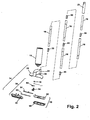
FIG. 2 is an exploded view of the stick cleaning implement ofFIG. 1 , showing a handle, a container, and a body at a lower portion thereof. -
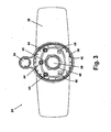
FIG. 3 is top view of an upper housing of the body ofFIG. 2 . -
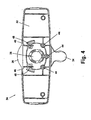
FIG. 4 is a bottom view of the upper housing ofFIG. 3 . -
FIG. 5 is an exploded view of a nozzle assembly of the body ofFIG. 2 . -
FIG. 6 is a sectional view taken through line 6-6 ofFIG. 5 . -
FIG. 7 is an exploded perspective view of a brush assembly of the body ofFIG. 2 . -
FIG. 8 is a partial sectional view taken through line 8-8 ofFIG. 1 , showing the dispenser in the off position. -
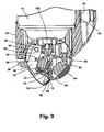
FIG. 9 is a partial sectional likeFIG. 8 but showing the dispenser in the on position. -
FIG. 10 is a sectional view taken through line 10-10 ofFIG. 1 . - Referring to the drawings, and in particular to
FIGS. 1 and2 , a small area carpet treating implement 10 in the form of a stick cleaner comprises ahandle assembly 12, abody assembly 14 and acontainer 16 removably attached to thebody assembly 14. Thehandle assembly 12 further comprises a plurality ofhandle segments 18 that are removably coupled viasegment connectors 20 which are commonly used in the stick floor cleaning industry. Agrip 22 provides a user interface at a first end of thehandle assembly 12 while a second end is removably coupled to thebody assembly 14. - Referring to
FIGS. 3 and4 , thebody assembly 14 further comprises anupper housing 24, anozzle assembly 26, and abrush assembly 28. Theupper housing 24 further comprises anexterior surface 30 and aninterior surface 32. Ahandle receiver 34 is integrally formed on a rear surface of theupper housing 24 and removably receives the second end of thehandle assembly 14. Acontainer receiver 36 is integrally formed on an upper surface of theupper housing 24 and removably receives thecontainer 16. In one embodiment thecontainer receiver 36 comprises a unique geometry that corresponds with a mating fitting on thecontainer 16 so that standard containers are not compatible with thecontainer receiver 36. In one embodiment, the unique geometry on thecontainer 16 is formed by removing the finger pad portion of the unique spray-through cap to expose avalve stem 102, pedestal, and mounting cup on thecontainer 16. Thecontainer receiver 36 design corresponds to the unique spray-through cap thus creating a unique geometry whereby only the unique spray-through cap will mate with thecontainer receiver 36. Acontainer aperture 38 is formed through theupper housing 24 and is generally aligned with a longitudinal axis of thecleaner container 16. A pair of lockinglever notches 40 is formed asymmetrically around a perimeter of theaperture 38. A plurality of stiffeningribs 42 are arranged about the perimeter of thecontainer receiver 36 to provide strength to the receiver wall and support thecontainer 16 as is commonly known in the art. A plurality ofscrew bosses 44 provides a mechanism to secure theupper housing 24 to thenozzle assembly 24 via screws or other commonly known fastening devices and techniques. Theinterior surface 32 of theupper housing 24 further comprises a pair ofpivot arms 46, each of which incorporates asingle pivot pin 48 that are axially aligned with each other between thepivot arms 46. - Referring to
FIG. 5 , thenozzle assembly 26 further comprises anozzle housing 50, a manifold cover, 52, and anangle conduit 54. The nozzle housing further comprises a pair ofsupport arms 56 that have throughopenings 58 at an upper portion thereof that receive the pivot pins 48 on thepivot arms 46 in theupper housing 24 to pivotally mount thenozzle housing 50 to theupper housing 24. A plurality ofrake blades 60 are formed along a bottom and rear surface of thenozzle housing 50, each further comprising afluid distribution conduit 62 formed therein. In one embodiment eachrake blade 60 is ramped, i.e., a rearward portion of the rake blade is wider than a forward portion of the rake blade. Each of thefluid distribution conduits 62 are in fluid communication via adistribution channel 64 formed across the width of thenozzle housing 50. Themanifold cover 52 further includes amanifold conduit 66 projecting upwardly therefrom and in fluid communication with thedistribution channel 64. Amanifold seal 53 is positioned between the manifold cover and thenozzle housing 50 to prevent leaking of fluid as it passes through thedistribution channel 64. Themanifold cover 52 is securely attached to thenozzle housing 50 via commonly known methods of heat staking, ultrasonic welding, adhesives, or screws. - Referring to
FIGS. 5 and6 , theangle conduit 54 further comprises abase portion 68 integrally formed with amain body 70 and forming afluid conduit 72 therethrough. Thebase portion 68 is fixedly mounted to themanifold cover 52 and surrounds themanifold conduit 66. Afluid inlet 74 is formed at the other end of thefluid conduit 72 and further comprises a cupseal retainer recess 76 that receives aseal 77 and aseal retainer 78. Themain body 70 further comprises anannular flange 80 concentric with an upper portion of thefluid conduit 72. A pair of opposed lockingears 82 are positioned in spaced relation to theannular flange 80 and interface with alock lever 84 that rotates about an outer surface of themain body 70 between theannular flange 80 and the lockingears 82. Thelock lever 84 is a rigid elongate structure comprising agrip 86 on one end and an aperture 88 on an opposing end. The aperture 88 comprises a pair of opposed notches 90 that correspond with the lockingears 82 of themain body 70. - In an alternate configuration the
seal 77,seal retainer 78, andangle conduit 54 can be replaced by an aerosol actuator and a flexible tube. The aerosol actuator comprises an L-shaped internal fluid conduit that is sealingly connected to the cleaner container valve stem 102 on an inlet side and to the flexible tube on an outlet side. The flexible tube is fluidly connected to themanifold conduit 66 formed on themanifold cover 52. Themanifold cover 52 can further comprise an upwardly ramped protrusion formed at the center portion thereof. - Referring to
FIG. 7 , thebrush assembly 28 further comprises abrush body 92 and a plurality ofbristles 94. Thebrush body 92 incorporates a plurality of mountingbosses 96 for mechanical attachment to theupper housing 24 by a corresponding number ofscrews 97. Adecorative bezel 98 surrounds thebristles 94 and snaps into place on thebrush body 92 in a conventional manner. Asqueegee 100 can be located on thebrush body 92 or thebezel 98 for use on bare floor surfaces. - The
container 16 is a conventional aerosol dispenser utilizing contents under pressure that are dispensed by engaging a commonly known valve assembly that includes avalve stem 102. Alternatively, thecontainer 16 can be any type of container that dispenses a treating composition to the surface to be treated. For example, thecontainer 16 can be a liquid container that feeds via gravity though a spring loaded normally closed valve or an optional commonly known pump assembly such as a trigger or battery powered motor coupled to a known pump. Furthermore, it is also contemplated that the invention can comprise more than onecontainer 16 with each container storing a different treating composition. The treating composition(s) can include any fluid, solid, or gas that can be used to clean or otherwise treat the surface to be treated. By way of example, one container can store a standard carpet cleaning solution, and a second container can store a topical treatment, such as an anti-stain, anti-soil, miticide, or peroxide composition, or other commonly known carpet treatments. It is further anticipated that the invention can comprise a hybrid whereby one of thecontainers 16 is an aerosol container and a second container is a liquid container. - Referring to the figures and particularly to
FIGS. 7 ,8 and9 , the treating implement 10 is readied for use thelock lever grip 86 is moved to the left as the user is facing thenozzle assembly 26 and placed in a "lock" position. With thelock lever 84 in the "lock" position, the locking lever notches 90 are offset from the lockingears 82 on theangle conduit 54 and thus prevent theangle conduit 54 from moving. Afull container 16 is inverted and placed in thecontainer receiver 36 formed in theupper housing 24 so that thevalve stem 102 slides within thecup seal retainer 78 and the sides of thecontainer 16 are aligned with thecontainer receiver 36 of theupper housing 24. To dispense the treating composition from thecontainer 16, the lock lever is moved to the right and placed in an "unlock" position. With thelock lever 84 in the "unlock" position, the locking lever notches 90 are aligned with the lockingears 82 on theangle conduit 54. - Referring to
FIGS. 9 and10 , to use the treating implement 10, the user grasps thehandle 12 at a convenient location with thebody 14 oriented in a downward position. The user places thenozzle assembly 26 on the surface to be treated and pushes down on thehandle 12. The downward force causes thenozzle assembly 26 to rotate about the pivot pins 48 associated with theupper housing 24 which, in turn, moves themanifold cover 52 andangle conduit 54 in a generally upward direction so that thevalve stem 102 of thecontainer 16 is forced upward. Upward movement of thevalve stem 102 releases the treating composition from thecontainer 16 to flow, as shown by arrows, through thecup seal retainer 78, through thefluid conduit 72, through themanifold conduit 66 and into thedistribution channel 64 within thenozzle housing 50. Now referring toFIG. 9 , the fluid is distributed across thedistribution channel 64 as shown by arrows and through theindividual distribution conduits 62 formed in each of therake blades 60. On carpeted surfaces, the rake blades penetrate the carpet nap and extend near the carpet backing thus separating the carpet fibers so that the treating composition can flow deep down into the carpet fibers. The treating composition can be further worked into the carpet by repeated downward stroking with either therake blades 60 or brush bristles 94. In one embodiment, the treating composition is a heavy traffic formulation that can be dried on the surface to be treated and can be subsequently removed via conventional vacuum cleaning. - Other embodiments of the treating implement not specifically shown herein are possible. For example, the treating implement can be adapted for use on bare floors by use of the
optional squeegee 100. Furthermore, therake blades 60 can be combined withadditional bristles 94 for an alternate agitation device.
Claims (15)
- A surface treating implement (10), comprising:a body (14) comprising;an upper housing (24) having a container receiver (36) integrally formed thereon: anda nozzle assembly (26) comprising a fluid conduit (72) fluidly connected to the container receiver (36);at least one container (16) selectively mounted to the container receiver (36) and containing a predetermined amount of a treating composition and having a dispensing opening in fluid communication with the fluid conduit (72);a handle (12) associated with the body (14); andwherein the nozzle assembly (26) is pivotally mounted to the upper housing (24) for selective displacement with respect thereto of a predetermined distance to release the treating composition from the container (16) through the fluid conduit (72) and onto a surface to be treated.
- The surface treating implement (10) according to claim 1, and further comprising a plurality of rake members (60) formed on the nozzle assembly (26).
- The surface treating implement (10) according to claim 2, wherein at least one of the plurality of rake members (60) comprises a ramped surface.
- The surface treating implement (10) according to claim 1, and wherein the container receiver (36) comprises a unique geometry that is complementary to a mating unique geometry on the container (16).
- The surface treating implement (10) according to claim 2, wherein the rake members (60) are adapted to penetrate carpet fibers on the surface to be treated and at least one fluid distribution conduit (62) is adapted to distribute the treating composition near a base of the carpet fibers.
- The surface treating implement (10) according to claim 1, and further comprising a brush assembly (28) adapted to agitate the surface to be treated after the treating composition has been applied to the surface to be treated.
- The surface treating implement (10) according to claim 6, wherein the brush assembly (28) is mounted to the nozzle assembly (26).
- The surface treating implement (10) according to claim 1, and further comprising a squeegee assembly (100) affixed to the body (14).
- The surface treating implement (10) according to claim 1, wherein the at least one container (16) is an aerosol container adapted to dispense fluid under pressure.
- The surface treating implement (10) according to claim 9, wherein the aerosol container has a valve stem (102) and the nozzle assembly (26) has an actuator that interfaces with the valve stem to displace the valve stem (102) with respect to the container receiver (36) to discharge the treating composition from the aerosol container as the nozzle assembly moves between the fluid retention position and the fluid discharge position.
- The surface treating implement (10) according to claim 1, wherein the at least one container (16) is a liquid container adapted to dispense fluid by gravity or is a pressurized container.
- The surface treating implement (10) according to claim 1, wherein the nozzle assembly (26) is pivotally mounted to the upper housing (24) for movement between a fluid discharge position and a fluid retention position.
- The surface treating implement (10) according to claim 1, wherein the at least one container (16) has a valved opening and the nozzle assembly (26) has an actuator that interfaces with a valve in the valved opening to displace the valve with respect to the container receiver (36) to discharge the treating composition from the at least one container (16) as the nozzle assembly moves between the fluid retention position and the fluid discharge position.
- The surface treating implement (10) according to any of claims 1-13, wherein the treating composition comprises at least one of a cleaning solution and a topical treatment.
- The surface treating implement (10) according claim 15, wherein the treating composition comprises a topical treatment, and the topical treatment comprises an anti-stain, anti-soil, miticide, or peroxide composition.
Applications Claiming Priority (2)
| Application Number | Priority Date | Filing Date | Title |
|---|---|---|---|
| US95446007P | 2007-08-07 | 2007-08-07 | |
| PCT/US2008/072439 WO2009021103A2 (en) | 2007-08-07 | 2008-08-07 | Surface treating implement |
Publications (4)
| Publication Number | Publication Date |
|---|---|
| EP2182831A2 EP2182831A2 (en) | 2010-05-12 |
| EP2182831A4 EP2182831A4 (en) | 2011-08-31 |
| EP2182831B1 EP2182831B1 (en) | 2013-07-31 |
| EP2182831B9 true EP2182831B9 (en) | 2014-04-16 |
Family
ID=40342036
Family Applications (1)
| Application Number | Title | Priority Date | Filing Date |
|---|---|---|---|
| EP08797358.2A Active EP2182831B9 (en) | 2007-08-07 | 2008-08-07 | Surface treating implement |
Country Status (5)
| Country | Link |
|---|---|
| US (1) | US8641309B2 (en) |
| EP (1) | EP2182831B9 (en) |
| CN (1) | CN101801253B (en) |
| AU (1) | AU2008285409B2 (en) |
| WO (1) | WO2009021103A2 (en) |
Families Citing this family (41)
| Publication number | Priority date | Publication date | Assignee | Title |
|---|---|---|---|---|
| EP2329754B1 (en) | 2009-12-03 | 2013-08-14 | Bissell Homecare, Inc. | Low moisture extraction deep cleaning |
| US9044852B2 (en) | 2010-10-26 | 2015-06-02 | Procter & Gamble | Cleaning device having onboard replaceable cleaning pad and onboard replaceable cleaning solution |
| US8684619B2 (en) | 2010-10-26 | 2014-04-01 | The Procter & Gamble Company | Cleaning device having plural and customizable cleaning surfaces |
| GB201101006D0 (en) * | 2011-01-21 | 2011-03-09 | Reckitt Benckiser Nv | Product |
| AU2012244292B2 (en) | 2011-11-04 | 2015-03-05 | Bissell Inc. | Enzyme cleaning composition and method of use |
| CN103284652A (en) * | 2012-02-23 | 2013-09-11 | 科沃斯机器人科技(苏州)有限公司 | Cleaning machine |
| US9643311B1 (en) * | 2014-04-16 | 2017-05-09 | Marshalltown Company | Octagonal extension handle |
| CN104120512B (en) * | 2014-08-13 | 2016-08-17 | 安徽华茂纺织股份有限公司 | It is exclusively used in the cleaning device of the big taker-in grid of carding machine |
| EP3119261B1 (en) * | 2015-03-13 | 2021-09-15 | Appennino di Ori Vittorio & C. S.N.C. | Sanitizing treadable mat |
| US10973387B2 (en) | 2015-06-26 | 2021-04-13 | Unger Marketing International, Llc | Multi-orientation cleaning device |
| US9877631B2 (en) | 2015-06-26 | 2018-01-30 | Unger Marketing International, Llc | Hard surface cleaning devices |
| US20190001480A1 (en) | 2015-08-17 | 2019-01-03 | Unger Marketing International, Llc | Tool handles having stationary and rotational portions |
| US20170049292A1 (en) | 2015-08-17 | 2017-02-23 | Unger Marketing International, Llc | Hard surface cleaning and conditioning assemblies |
| USD769129S1 (en) | 2015-09-21 | 2016-10-18 | Unger Marketing International, Llc | Flexible pouch |
| US10021872B2 (en) * | 2015-10-29 | 2018-07-17 | Ashok Biyani | Combination duster and sprayer device |
| USD804266S1 (en) | 2016-02-04 | 2017-12-05 | Marshalltown Company | Concrete placer tool including octagonal pole handle |
| US10517287B2 (en) * | 2016-06-25 | 2019-12-31 | Dustin Oralleus Burrell | Extensible pesticide applicator |
| USD852444S1 (en) | 2016-08-16 | 2019-06-25 | Unger Marketing International, Llc | Bottle |
| USD864511S1 (en) | 2016-08-16 | 2019-10-22 | Unger Marketing International, Llc | Pole grip |
| USD840626S1 (en) | 2016-09-14 | 2019-02-12 | Unger Marketing International, Llc | Hard surface cleaning device |
| WO2018053170A1 (en) | 2016-09-14 | 2018-03-22 | Unger Marketing International, Llc | Hard surface cleaning devices |
| USD840625S1 (en) | 2016-09-14 | 2019-02-12 | Unger Marketing International, Llc | Hard surface cleaning device |
| USD850883S1 (en) | 2016-10-17 | 2019-06-11 | Unger Marketing International, Llc | Tool handle |
| USD848093S1 (en) | 2016-10-17 | 2019-05-07 | Unger Marketing International, Llc | Hard surface cleaning device |
| US10113323B2 (en) * | 2016-10-31 | 2018-10-30 | Stego Industries, LLC | Concrete forming stake apparatus |
| US10508946B2 (en) * | 2017-02-01 | 2019-12-17 | Stego Industries, LLC | Wet screed hardware apparatus |
| USD866899S1 (en) | 2017-09-11 | 2019-11-12 | Unger Marketing International, Llc | Tool grip |
| USD867705S1 (en) | 2017-09-11 | 2019-11-19 | Unger Marketing International, Llc | Bottle |
| USD881494S1 (en) | 2017-09-11 | 2020-04-14 | Unger Marketing International, Llc | Tool grip |
| USD904704S1 (en) | 2018-03-14 | 2020-12-08 | Unger Marketing International, Llc | Hard surface cleaning device |
| US11529037B2 (en) | 2019-01-07 | 2022-12-20 | Bissell, Inc. | Surface cleaning apparatus having a fluid distributor |
| USD911844S1 (en) | 2019-01-18 | 2021-03-02 | Unger Marketing International, Llc | Bottle for a cleaning device |
| CN110044140A (en) * | 2019-05-16 | 2019-07-23 | 李锦标 | Carpet fast drying machine and carpet rapid-curing cutback method |
| US11147428B2 (en) * | 2019-07-31 | 2021-10-19 | Carl Freudenberg Kg | Floor mop |
| KR102264455B1 (en) * | 2020-08-03 | 2021-06-11 | 문연우 | Fiber Discfilter comprising groove forming means on the surface of filter cloths |
| US20220174931A1 (en) * | 2020-12-06 | 2022-06-09 | Rafael Caceres | Wasp Catcher |
| CA3152680C (en) | 2021-03-17 | 2025-02-11 | Dupray Ventures Inc. | Spot cleaner apparatus |
| USD984073S1 (en) * | 2021-04-28 | 2023-04-18 | Vikan A/S | Handle |
| US12377372B2 (en) * | 2021-06-08 | 2025-08-05 | Greatpyr Resources Llc | Apparatus, systems, and processes employing wet/dry suction filter with chicaned suction head |
| USD1017156S1 (en) | 2022-05-09 | 2024-03-05 | Dupray Ventures Inc. | Cleaner |
| USD1135288S1 (en) * | 2025-08-25 | 2026-07-14 | Yufeng LU | Duster |
Family Cites Families (48)
| Publication number | Priority date | Publication date | Assignee | Title |
|---|---|---|---|---|
| US3850656A (en) * | 1970-07-13 | 1974-11-26 | W Brown | Typing error correction system |
| US3679319A (en) * | 1971-01-13 | 1972-07-25 | Ashcombe Prod Co | Cleaning attachment for elevated spray device |
| US3783474A (en) * | 1972-07-03 | 1974-01-08 | Health Mor Inc | Shag rug attachment for suction cleaner nozzle |
| SE427082B (en) * | 1980-03-07 | 1983-03-07 | Electrolux Ab | DEVICE FOR COATING APPLIANCES, PREFERRED TO BONAR |
| US5735620A (en) * | 1996-03-11 | 1998-04-07 | Ford; Peggy D. | Multi-purpose cleaning tool |
| US6065182A (en) * | 1996-06-07 | 2000-05-23 | Royal Appliance Mfg. Co. | Cordless wet mop and vacuum assembly |
| GB2342403B (en) | 1998-10-09 | 2000-09-06 | Christian Benn Ebede | Cleansing device |
| US7163349B2 (en) * | 1998-11-09 | 2007-01-16 | The Procter & Gamble Company | Combined cleaning pad and cleaning implement |
| US6579023B2 (en) * | 1998-12-01 | 2003-06-17 | The Procter & Gamble Company | Cleaning implements |
| CN1161070C (en) * | 1999-12-21 | 2004-08-11 | 花王株式会社 | Pipe connections and cleaning tools |
| US6349451B1 (en) * | 2000-01-28 | 2002-02-26 | Robert D. Newman/Specialty Products Of Greenwood, Missouri, Inc. | Universal tool handle configured for various extension pole connectors |
| US7048458B2 (en) * | 2000-03-24 | 2006-05-23 | The Clorox Company | Fluid valve and actuator for inverted fluid reservoir |
| ES2167247B1 (en) | 2000-07-06 | 2003-04-01 | Villahoz M Inmaculada Nieto | APPLICATOR DEVICE FOR SOIL PRODUCTS. |
| US6663307B2 (en) * | 2001-09-14 | 2003-12-16 | S. C. Johnson & Son, Inc. | Apparatus for spraying a remote target or area |
| US6866165B2 (en) * | 2001-09-14 | 2005-03-15 | S.C. Johnson & Son, Inc. | Spray canister |
| DE10205507A1 (en) | 2002-02-04 | 2003-08-07 | Alpla Werke | Floor mop has blow-molded bottle mounted on handle which has bellows section at its base, on which cap with valve is fitted, so that when bellows is squeezed cleaning liquid is dispensed on to floor |
| ITRM20020042U1 (en) * | 2002-03-01 | 2003-09-01 | F I M M S P A | MODULAR HANDLE PERFECTED, IN PARTICULAR HANDLE FOR PURPOSES AND SIMILAR. |
| AU2003219311A1 (en) * | 2002-04-03 | 2003-10-13 | Reckitt Benckiser (Uk) Limited | Cleaning apparatus and method for using the same |
| US6820301B2 (en) * | 2002-05-07 | 2004-11-23 | Quickie Manufacturing Corporation | Cleaning implement with removable cleaning element |
| US6663309B2 (en) * | 2002-05-08 | 2003-12-16 | Wki Holding Company, Inc. | Cleaning utensil |
| DE10224607B4 (en) * | 2002-06-04 | 2008-03-13 | Lts Lohmann Therapie-Systeme Ag | Film-form, disintegratable preparations for drug release and process for their preparation |
| US6854919B2 (en) * | 2002-06-20 | 2005-02-15 | S.C. Johnson & Son, Inc. | Push-lock handle assembly |
| US6789705B2 (en) | 2002-11-14 | 2004-09-14 | Frank M. Drew | Aerosol dispenser spraying apparatus |
| US6701578B1 (en) * | 2002-12-12 | 2004-03-09 | Jung-Hui Lu | Telescopic handle for a cleaning implement |
| US20040144406A1 (en) * | 2003-01-16 | 2004-07-29 | Aram Garabedian | Dry aerosol carpet cleaning process |
| US7007338B2 (en) * | 2003-01-16 | 2006-03-07 | Garabedian Jr Aram | Advanced aerosol cleaning system |
| US20040141797A1 (en) * | 2003-01-16 | 2004-07-22 | Aram Garabedian | Advanced aerosol cleaning system |
| US6953299B2 (en) * | 2003-01-16 | 2005-10-11 | The Clorox Company | Cleaning implement with interchangeable tool heads |
| US20040146332A1 (en) * | 2003-01-27 | 2004-07-29 | Top Innovations, Inc. | Telescoping cleaning apparatus with refillable fluid reservoir and interchangeable heads |
| US6868989B2 (en) * | 2003-03-10 | 2005-03-22 | S.C. Johnson & Son, Inc. | Cleaner with adjustable aerosol canister retainer |
| US6692172B1 (en) * | 2003-04-14 | 2004-02-17 | Hsing-Yuan Hsu | Mop assembly with liquid detergent supply |
| KR100504259B1 (en) * | 2003-07-19 | 2005-07-27 | 용성전기 주식회사 | Switch capable of automatically uniting body and handle part |
| KR20050100251A (en) | 2004-04-13 | 2005-10-18 | 엘지전자 주식회사 | Nozzle assembly of vacuum cleaner for both wet and dry cleaning |
| GB2412301A (en) | 2004-03-23 | 2005-09-28 | Reckitt Benckiser Inc | Cleaning device |
| US7182223B2 (en) * | 2004-03-29 | 2007-02-27 | S.C. Johnson & Son, Inc. | Detachable tube assembly |
| KR20050103088A (en) | 2004-04-24 | 2005-10-27 | 엘지전자 주식회사 | A brush-unit of vacuum cleaner for both wet and dry cleaning |
| US6972420B2 (en) * | 2004-04-28 | 2005-12-06 | Intel Corporation | Atomic beam to protect a reticle |
| US7065838B2 (en) * | 2004-05-19 | 2006-06-27 | The Clorox Company | Locking, segmented cleaning implement handle |
| GB0415516D0 (en) * | 2004-07-10 | 2004-08-11 | Reckitt Benckiser Nv | Apparatus and method of using the same |
| US6960042B1 (en) * | 2005-01-18 | 2005-11-01 | Tien Jong Hsiao | Versatile mop |
| US7618206B2 (en) * | 2005-03-14 | 2009-11-17 | Avet. Ag | Cleaning device |
| JP4734124B2 (en) * | 2005-04-05 | 2011-07-27 | ユニ・チャーム株式会社 | Cleaning tool |
| US7758525B2 (en) * | 2005-06-03 | 2010-07-20 | L'oreal | Massage and/or dispensing appliance |
| EP1762509B1 (en) | 2005-09-07 | 2008-06-25 | Reckitt Benckiser (UK) LIMITED | Cleaning device and method |
| US20070122227A1 (en) * | 2005-11-30 | 2007-05-31 | Coatings Management Systems, Inc. | Assembly for mounting paint spray gun to extension pole with paint applicator |
| KR20070078482A (en) | 2006-01-27 | 2007-08-01 | 주식회사 대우일렉트로닉스 | Mop Water Supply Device for Vacuum Cleaner |
| US20070231046A1 (en) * | 2006-03-14 | 2007-10-04 | Eastway Fair Company Limited | Cleaning device having heated cleaning solution |
| US20120227763A1 (en) * | 2011-03-08 | 2012-09-13 | Eric Paris Hayes | Floor mop |
-
2008
- 2008-08-07 AU AU2008285409A patent/AU2008285409B2/en not_active Ceased
- 2008-08-07 CN CN200880102042.9A patent/CN101801253B/en active Active
- 2008-08-07 US US12/672,359 patent/US8641309B2/en active Active
- 2008-08-07 WO PCT/US2008/072439 patent/WO2009021103A2/en not_active Ceased
- 2008-08-07 EP EP08797358.2A patent/EP2182831B9/en active Active
Also Published As
| Publication number | Publication date |
|---|---|
| CN101801253A (en) | 2010-08-11 |
| US20110179591A1 (en) | 2011-07-28 |
| AU2008285409B2 (en) | 2012-07-05 |
| CN101801253B (en) | 2013-06-12 |
| EP2182831A4 (en) | 2011-08-31 |
| EP2182831A2 (en) | 2010-05-12 |
| WO2009021103A2 (en) | 2009-02-12 |
| EP2182831B1 (en) | 2013-07-31 |
| AU2008285409A1 (en) | 2009-02-12 |
| US8641309B2 (en) | 2014-02-04 |
| WO2009021103A3 (en) | 2009-04-30 |
Similar Documents
| Publication | Publication Date | Title |
|---|---|---|
| EP2182831B1 (en) | Surface treating implement | |
| EP3315023B1 (en) | Pet bathing system | |
| CA2816773C (en) | Extraction cleaner | |
| EP2330962B1 (en) | Plural nozzle cleaning implement | |
| EP2805659B1 (en) | Extraction cleaner | |
| US7350262B2 (en) | Floor care appliance with tool caddy | |
| US8152400B2 (en) | Surface cleaner with removable wand | |
| CN117582145B (en) | Rod assembly and suction cleaner | |
| US5367740A (en) | Hand-held surface cleaning apparatus | |
| US20050173560A1 (en) | Trigger sprayer with ergonomic trigger | |
| US11930971B2 (en) | Floor cleaner | |
| WO2016025239A1 (en) | Extractor cleaning machine | |
| EP4106594B1 (en) | Floor cleaner |
Legal Events
| Date | Code | Title | Description |
|---|---|---|---|
| PUAI | Public reference made under article 153(3) epc to a published international application that has entered the european phase |
Free format text: ORIGINAL CODE: 0009012 |
|
| 17P | Request for examination filed |
Effective date: 20100218 |
|
| AK | Designated contracting states |
Kind code of ref document: A2 Designated state(s): AT BE BG CH CY CZ DE DK EE ES FI FR GB GR HR HU IE IS IT LI LT LU LV MC MT NL NO PL PT RO SE SI SK TR |
|
| AX | Request for extension of the european patent |
Extension state: AL BA MK RS |
|
| RIN1 | Information on inventor provided before grant (corrected) |
Inventor name: KRZEMINSKI, JAMES, A. Inventor name: BENACQUISTO, JUSTIN Inventor name: LENKIEWICZ, KENNETH, M. Inventor name: VANDERBILT, HERBERT, J. Inventor name: CAIN, KELLI, A. Inventor name: MAHAFFY, DONALD, J. Inventor name: HALEY, KEVIN Inventor name: PERRY, JOSEPH, P. |
|
| A4 | Supplementary search report drawn up and despatched |
Effective date: 20110802 |
|
| RIC1 | Information provided on ipc code assigned before grant |
Ipc: A47L 13/00 20060101ALI20110727BHEP Ipc: A47L 13/22 20060101AFI20110727BHEP |
|
| 17Q | First examination report despatched |
Effective date: 20120614 |
|
| DAX | Request for extension of the european patent (deleted) | ||
| GRAP | Despatch of communication of intention to grant a patent |
Free format text: ORIGINAL CODE: EPIDOSNIGR1 |
|
| GRAS | Grant fee paid |
Free format text: ORIGINAL CODE: EPIDOSNIGR3 |
|
| GRAA | (expected) grant |
Free format text: ORIGINAL CODE: 0009210 |
|
| AK | Designated contracting states |
Kind code of ref document: B1 Designated state(s): AT BE BG CH CY CZ DE DK EE ES FI FR GB GR HR HU IE IS IT LI LT LU LV MC MT NL NO PL PT RO SE SI SK TR |
|
| REG | Reference to a national code |
Ref country code: GB Ref legal event code: FG4D Ref country code: CH Ref legal event code: EP |
|
| REG | Reference to a national code |
Ref country code: AT Ref legal event code: REF Ref document number: 624122 Country of ref document: AT Kind code of ref document: T Effective date: 20130815 |
|
| REG | Reference to a national code |
Ref country code: IE Ref legal event code: FG4D |
|
| REG | Reference to a national code |
Ref country code: DE Ref legal event code: R096 Ref document number: 602008026460 Country of ref document: DE Effective date: 20130926 |
|
| REG | Reference to a national code |
Ref country code: AT Ref legal event code: MK05 Ref document number: 624122 Country of ref document: AT Kind code of ref document: T Effective date: 20130731 |
|
| REG | Reference to a national code |
Ref country code: NL Ref legal event code: VDEP Effective date: 20130731 |
|
| REG | Reference to a national code |
Ref country code: LT Ref legal event code: MG4D |
|
| PG25 | Lapsed in a contracting state [announced via postgrant information from national office to epo] |
Ref country code: NO Free format text: LAPSE BECAUSE OF FAILURE TO SUBMIT A TRANSLATION OF THE DESCRIPTION OR TO PAY THE FEE WITHIN THE PRESCRIBED TIME-LIMIT Effective date: 20131031 Ref country code: PT Free format text: LAPSE BECAUSE OF FAILURE TO SUBMIT A TRANSLATION OF THE DESCRIPTION OR TO PAY THE FEE WITHIN THE PRESCRIBED TIME-LIMIT Effective date: 20131202 Ref country code: IS Free format text: LAPSE BECAUSE OF FAILURE TO SUBMIT A TRANSLATION OF THE DESCRIPTION OR TO PAY THE FEE WITHIN THE PRESCRIBED TIME-LIMIT Effective date: 20131130 Ref country code: BE Free format text: LAPSE BECAUSE OF FAILURE TO SUBMIT A TRANSLATION OF THE DESCRIPTION OR TO PAY THE FEE WITHIN THE PRESCRIBED TIME-LIMIT Effective date: 20130731 Ref country code: AT Free format text: LAPSE BECAUSE OF FAILURE TO SUBMIT A TRANSLATION OF THE DESCRIPTION OR TO PAY THE FEE WITHIN THE PRESCRIBED TIME-LIMIT Effective date: 20130731 Ref country code: SE Free format text: LAPSE BECAUSE OF FAILURE TO SUBMIT A TRANSLATION OF THE DESCRIPTION OR TO PAY THE FEE WITHIN THE PRESCRIBED TIME-LIMIT Effective date: 20130731 Ref country code: HR Free format text: LAPSE BECAUSE OF FAILURE TO SUBMIT A TRANSLATION OF THE DESCRIPTION OR TO PAY THE FEE WITHIN THE PRESCRIBED TIME-LIMIT Effective date: 20130731 Ref country code: CY Free format text: LAPSE BECAUSE OF FAILURE TO SUBMIT A TRANSLATION OF THE DESCRIPTION OR TO PAY THE FEE WITHIN THE PRESCRIBED TIME-LIMIT Effective date: 20130828 Ref country code: LT Free format text: LAPSE BECAUSE OF FAILURE TO SUBMIT A TRANSLATION OF THE DESCRIPTION OR TO PAY THE FEE WITHIN THE PRESCRIBED TIME-LIMIT Effective date: 20130731 |
|
| PG25 | Lapsed in a contracting state [announced via postgrant information from national office to epo] |
Ref country code: LV Free format text: LAPSE BECAUSE OF FAILURE TO SUBMIT A TRANSLATION OF THE DESCRIPTION OR TO PAY THE FEE WITHIN THE PRESCRIBED TIME-LIMIT Effective date: 20130731 Ref country code: NL Free format text: LAPSE BECAUSE OF FAILURE TO SUBMIT A TRANSLATION OF THE DESCRIPTION OR TO PAY THE FEE WITHIN THE PRESCRIBED TIME-LIMIT Effective date: 20130731 Ref country code: SI Free format text: LAPSE BECAUSE OF FAILURE TO SUBMIT A TRANSLATION OF THE DESCRIPTION OR TO PAY THE FEE WITHIN THE PRESCRIBED TIME-LIMIT Effective date: 20130731 Ref country code: GR Free format text: LAPSE BECAUSE OF FAILURE TO SUBMIT A TRANSLATION OF THE DESCRIPTION OR TO PAY THE FEE WITHIN THE PRESCRIBED TIME-LIMIT Effective date: 20131101 Ref country code: FI Free format text: LAPSE BECAUSE OF FAILURE TO SUBMIT A TRANSLATION OF THE DESCRIPTION OR TO PAY THE FEE WITHIN THE PRESCRIBED TIME-LIMIT Effective date: 20130731 Ref country code: PL Free format text: LAPSE BECAUSE OF FAILURE TO SUBMIT A TRANSLATION OF THE DESCRIPTION OR TO PAY THE FEE WITHIN THE PRESCRIBED TIME-LIMIT Effective date: 20130731 |
|
| PG25 | Lapsed in a contracting state [announced via postgrant information from national office to epo] |
Ref country code: CY Free format text: LAPSE BECAUSE OF FAILURE TO SUBMIT A TRANSLATION OF THE DESCRIPTION OR TO PAY THE FEE WITHIN THE PRESCRIBED TIME-LIMIT Effective date: 20130731 |
|
| REG | Reference to a national code |
Ref country code: CH Ref legal event code: PL |
|
| PG25 | Lapsed in a contracting state [announced via postgrant information from national office to epo] |
Ref country code: LI Free format text: LAPSE BECAUSE OF NON-PAYMENT OF DUE FEES Effective date: 20130831 Ref country code: DE Free format text: LAPSE BECAUSE OF NON-PAYMENT OF DUE FEES Effective date: 20140301 Ref country code: DK Free format text: LAPSE BECAUSE OF FAILURE TO SUBMIT A TRANSLATION OF THE DESCRIPTION OR TO PAY THE FEE WITHIN THE PRESCRIBED TIME-LIMIT Effective date: 20130731 Ref country code: EE Free format text: LAPSE BECAUSE OF FAILURE TO SUBMIT A TRANSLATION OF THE DESCRIPTION OR TO PAY THE FEE WITHIN THE PRESCRIBED TIME-LIMIT Effective date: 20130731 Ref country code: RO Free format text: LAPSE BECAUSE OF FAILURE TO SUBMIT A TRANSLATION OF THE DESCRIPTION OR TO PAY THE FEE WITHIN THE PRESCRIBED TIME-LIMIT Effective date: 20130731 Ref country code: CH Free format text: LAPSE BECAUSE OF NON-PAYMENT OF DUE FEES Effective date: 20130831 Ref country code: MC Free format text: LAPSE BECAUSE OF FAILURE TO SUBMIT A TRANSLATION OF THE DESCRIPTION OR TO PAY THE FEE WITHIN THE PRESCRIBED TIME-LIMIT Effective date: 20130731 Ref country code: SK Free format text: LAPSE BECAUSE OF FAILURE TO SUBMIT A TRANSLATION OF THE DESCRIPTION OR TO PAY THE FEE WITHIN THE PRESCRIBED TIME-LIMIT Effective date: 20130731 Ref country code: CZ Free format text: LAPSE BECAUSE OF FAILURE TO SUBMIT A TRANSLATION OF THE DESCRIPTION OR TO PAY THE FEE WITHIN THE PRESCRIBED TIME-LIMIT Effective date: 20130731 |
|
| REG | Reference to a national code |
Ref country code: IE Ref legal event code: MM4A |
|
| REG | Reference to a national code |
Ref country code: DE Ref legal event code: R119 Ref document number: 602008026460 Country of ref document: DE Effective date: 20140301 |
|
| PG25 | Lapsed in a contracting state [announced via postgrant information from national office to epo] |
Ref country code: IT Free format text: LAPSE BECAUSE OF FAILURE TO SUBMIT A TRANSLATION OF THE DESCRIPTION OR TO PAY THE FEE WITHIN THE PRESCRIBED TIME-LIMIT Effective date: 20130731 Ref country code: ES Free format text: LAPSE BECAUSE OF FAILURE TO SUBMIT A TRANSLATION OF THE DESCRIPTION OR TO PAY THE FEE WITHIN THE PRESCRIBED TIME-LIMIT Effective date: 20130731 |
|
| PLBE | No opposition filed within time limit |
Free format text: ORIGINAL CODE: 0009261 |
|
| STAA | Information on the status of an ep patent application or granted ep patent |
Free format text: STATUS: NO OPPOSITION FILED WITHIN TIME LIMIT |
|
| 26N | No opposition filed |
Effective date: 20140502 |
|
| REG | Reference to a national code |
Ref country code: FR Ref legal event code: ST Effective date: 20140618 |
|
| PG25 | Lapsed in a contracting state [announced via postgrant information from national office to epo] |
Ref country code: IE Free format text: LAPSE BECAUSE OF NON-PAYMENT OF DUE FEES Effective date: 20130807 |
|
| PG25 | Lapsed in a contracting state [announced via postgrant information from national office to epo] |
Ref country code: FR Free format text: LAPSE BECAUSE OF NON-PAYMENT OF DUE FEES Effective date: 20130930 |
|
| PG25 | Lapsed in a contracting state [announced via postgrant information from national office to epo] |
Ref country code: MT Free format text: LAPSE BECAUSE OF FAILURE TO SUBMIT A TRANSLATION OF THE DESCRIPTION OR TO PAY THE FEE WITHIN THE PRESCRIBED TIME-LIMIT Effective date: 20130731 Ref country code: TR Free format text: LAPSE BECAUSE OF FAILURE TO SUBMIT A TRANSLATION OF THE DESCRIPTION OR TO PAY THE FEE WITHIN THE PRESCRIBED TIME-LIMIT Effective date: 20130731 |
|
| PG25 | Lapsed in a contracting state [announced via postgrant information from national office to epo] |
Ref country code: HU Free format text: LAPSE BECAUSE OF FAILURE TO SUBMIT A TRANSLATION OF THE DESCRIPTION OR TO PAY THE FEE WITHIN THE PRESCRIBED TIME-LIMIT; INVALID AB INITIO Effective date: 20080807 Ref country code: BG Free format text: LAPSE BECAUSE OF FAILURE TO SUBMIT A TRANSLATION OF THE DESCRIPTION OR TO PAY THE FEE WITHIN THE PRESCRIBED TIME-LIMIT Effective date: 20130731 Ref country code: LU Free format text: LAPSE BECAUSE OF NON-PAYMENT OF DUE FEES Effective date: 20130807 |
|
| REG | Reference to a national code |
Ref country code: GB Ref legal event code: 732E Free format text: REGISTERED BETWEEN 20201001 AND 20201007 |
|
| P01 | Opt-out of the competence of the unified patent court (upc) registered |
Effective date: 20230528 |
|
| PGFP | Annual fee paid to national office [announced via postgrant information from national office to epo] |
Ref country code: GB Payment date: 20250725 Year of fee payment: 18 |