EP2182719A2 - Imaging apparatus, variable speed imaging method, and recording medium storing program thereof - Google Patents
Imaging apparatus, variable speed imaging method, and recording medium storing program thereof Download PDFInfo
- Publication number
- EP2182719A2 EP2182719A2 EP09170377A EP09170377A EP2182719A2 EP 2182719 A2 EP2182719 A2 EP 2182719A2 EP 09170377 A EP09170377 A EP 09170377A EP 09170377 A EP09170377 A EP 09170377A EP 2182719 A2 EP2182719 A2 EP 2182719A2
- Authority
- EP
- European Patent Office
- Prior art keywords
- frame
- thinning
- rate
- frame rate
- imaging
- Prior art date
- Legal status (The legal status is an assumption and is not a legal conclusion. Google has not performed a legal analysis and makes no representation as to the accuracy of the status listed.)
- Granted
Links
Images





Classifications
-
- H—ELECTRICITY
- H04—ELECTRIC COMMUNICATION TECHNIQUE
- H04N—PICTORIAL COMMUNICATION, e.g. TELEVISION
- H04N5/00—Details of television systems
- H04N5/76—Television signal recording
- H04N5/765—Interface circuits between an apparatus for recording and another apparatus
- H04N5/77—Interface circuits between an apparatus for recording and another apparatus between a recording apparatus and a television camera
-
- H—ELECTRICITY
- H04—ELECTRIC COMMUNICATION TECHNIQUE
- H04N—PICTORIAL COMMUNICATION, e.g. TELEVISION
- H04N23/00—Cameras or camera modules comprising electronic image sensors; Control thereof
- H04N23/60—Control of cameras or camera modules
-
- H—ELECTRICITY
- H04—ELECTRIC COMMUNICATION TECHNIQUE
- H04N—PICTORIAL COMMUNICATION, e.g. TELEVISION
- H04N23/00—Cameras or camera modules comprising electronic image sensors; Control thereof
- H04N23/70—Circuitry for compensating brightness variation in the scene
- H04N23/73—Circuitry for compensating brightness variation in the scene by influencing the exposure time
-
- H—ELECTRICITY
- H04—ELECTRIC COMMUNICATION TECHNIQUE
- H04N—PICTORIAL COMMUNICATION, e.g. TELEVISION
- H04N9/00—Details of colour television systems
- H04N9/79—Processing of colour television signals in connection with recording
- H04N9/80—Transformation of the television signal for recording, e.g. modulation, frequency changing; Inverse transformation for playback
- H04N9/804—Transformation of the television signal for recording, e.g. modulation, frequency changing; Inverse transformation for playback involving pulse code modulation of the colour picture signal components
- H04N9/8042—Transformation of the television signal for recording, e.g. modulation, frequency changing; Inverse transformation for playback involving pulse code modulation of the colour picture signal components involving data reduction
Definitions
- the present invention relates to an imaging apparatus, a variable speed imaging method, and a recording medium storing a program thereof.
- an art for dynamically changing the frame rate when shooting a moving image is known (refer to, for example, Japanese Patent Application Laid-Open (Kokai) Publication No. 2002-320198 ).
- the frame rate can be dynamically changed between 30 frames per second (fps) and 300fps
- the number of frames is thinned-out to 1/10 th , which are encoded and saved as a file.
- the frame rate is changed by user operation to shoot at 300fps, all frames captured from the image sensor element at 300fps are encoded and saved as a file.
- the frame rate for the actual recording of the frames is changed from 30fps to 300fps at the point in time where the operation instructing the change is performed by the user.
- An object of the present invention is to provide an imaging apparatus, a variable speed imaging method, and a recording medium storing a program thereof that ensure the high-speed shooting of a decisive moment even in a case where the subject moves suddenly and a decisive moment occurs or a case where the reaction of the user's operation is delayed.
- a imaging apparatus comprising: an imaging means for sequentially imaging a subject at a predetermined frame rate; a holding means for sequentially holding a plurality of frames sequentially imaged by the imaging means; a specifying means for specifying a frame rate at which frames are extracted from the holding means according to a user operation; a frame thinning means for sequentially extracting frames from the holding means at a thinning rate based on a frame rate specified by the specifying means; and a storing means for storing frames sequentially extracted by the frame thinning means as a moving image file; wherein when the specifying means specifies a frame rate change according to a user operation, the frame thinning means applies a thinning rate based on a changed frame rate from a frame traced back in time rather than when the change is specified.
- a variable speed imaging method comprising: a step for sequentially imaging a subject at a predetermined frame rate; a step for sequentially holding a plurality of frames sequentially imaged; a step for specifying a frame rate at which the frames held are extracted according to a user operation; a step for sequentially extracting the frames held at a thinning rate based on the frame rate specified; a step for storing the frames sequentially extracted as a moving image file; and a step for, when a frame rate change is specified according to a user operation, applying a thinning rate based on a changed frame rate from a frame traced back in time rather than when the change is specified.
- a computer-readable storage medium having stored thereon a program for controlling operation of a moving image imaging apparatus for imaging a moving image that is executable by a computer to perform a process comprising: imaging processing for sequentially imaging a subject at a predetermined frame rate; holding processing for sequentially holding a plurality of frames sequentially imaged by the imaging processing; specifying processing for specifying a frame rate at which frames held by the holding processing are extracted according to a user operation; frame thinning processing for sequentially extracting frames held by the holding processing at a thinning rate based on a frame rate specified by the specifying processing; storing processing for storing frames sequentially extracted by the frame thinning processing as a moving image file; and processing for, when a frame rate change is specified by the specifying processing according to a user operation, applying a thinning rate based on a changed frame rate from a frame traced back in time rather than when the change is specified.
- the thinning rate based on the changed frame rate is applied from frames traced back in time rather than when the change is specified. Therefore, even in a case where the subject moves suddenly and a decisive moment occurs or a case where the reaction of the user' s operation is delayed, an advantage is acquired in that high-speed shooting can be reliably performed at the decisive moment.
- FIG. 1 is a block diagram of a configuration of an imaging apparatus (digital camera) according to an embodiment of the present invention.
- an image inputting section 1 includes an optical system such as a lens, an image sensor element, etc.
- the image inputting section 1 captures images at a maximum frame rate (such as 300fps) and supplies the images to a frame buffer 2.
- the frame buffer 2 includes a ring buffer and sequentially buffers the images captured by the image inputting section 1.
- a continuous shooting speed change controlling section 3 includes a ring-shaped controller provided around the periphery of a lens tube containing the lens.
- the continuous shooting speed change controlling section 3 generates an instruction to change continuous shooting speed (recording frame rate) to, for example, 30fps, 150fps, or 300fps by rotating the ring-shaped controller.
- a frame thinning setting section 4 sets frame thinning information when a current continuous shooting speed instructed is detected based on the status of the continuous shooting speed change controlling section 3.
- the frame thinning information indicates, for example, from which image, and by what acquisition interval (thinning rate), the extraction of the images buffered by the frame buffer 2 is started.
- a frame thinning processing section 5 extracts, from among the images stored in the frame buffer 2, images traced back a predetermined amount of time at a predetermined acquisition interval.
- the frame thinning processing section 5 then supplies the extracted images to an image compressing section 6.
- the image compressing section 6 compresses and encodes the images extracted from the frame buffer 2 by the frame thinning processing section 5 using a predetermined codec.
- the image compressing section 6 supplies the compressed and encoded images to a file converting section 7.
- the file converting section 7 supplies the moving image format file to a recording medium 8.
- the recording medium 8 includes an internal memory or an external memory, and stores the moving image files thereon.
- FIG. 2 is a conceptual diagram of a configuration of the frame buffer 2 in the imaging apparatus according to the embodiment.
- the frame buffer 2 holds a buffer size x, a buffer head position y, a buffer frame count m, and a buffer head frame number n, and sequentially stores images or, in other words, frames captured from the image imputing section 1. Every time a frame is generated in the image inputting section 1, the frame buffer 2 stores a pointer pointing to the frame, namely the buffer head position (currently targeted position) y.
- the size x of the frame buffer 2 corresponds to the number of frames equivalent to more than the amount of time for changing the frame rates of frames traced back from the point in time at which the continuous shooting speed change control is performed by user operation.
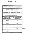
- FIG. 3 is a conceptual diagram of a configuration of the frame thinning information in the imaging apparatus according to the embodiment.
- the frame thinning information is stored in a ring buffer and includes an information size s, an information head position (currently targeted position) t, and an information amount j.
- a switching frame number, and an acquisition interval that is used starting from this switching frame number are sequentially stored as part of the frame thinning information every time continuous shooting speed change control is performed by user operation.
- the switching frame number indicates from which image the change of the acquisition interval is applied.
- the acquisition interval indicates an interval at which frames are acquired from the frame buffer 2. For example, when the maximum frame rate is "1" (no thinning) and the frame rate is 1/10 th , the acquisition interval is "10".
- the information size s is required to be a size greater than the number of times the change control can be performed within the trace back time so that control information recordings are not missed.
- frame numbers "1” to “1499” are acquired at a frame rate of 1/10 th .
- Frame numbers “1500” to “2999” are acquired at a frame rate of 1/1 (maximum frame rate).
- Frame numbers "3000” to “4499” are acquired at a frame rate of 1/2.
- Frame number "4500” and subsequent frames are acquired at a frame rate of 1/10 th .
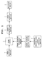
- FIG. 4 and FIG. 5 are flowcharts (operation programs) explaining the operations of the imaging apparatus according to the embodiment.
- a recording frame rate of this imaging apparatus can be switched to 30fps, 150 fps, and 300fps based on the user' s operation of the continuous shooting speed change controlling section 3.
- images can be stored in the frame buffer 2 at 300fps.
- the frames are thinned-out to 1/10 th and extracted.
- the frames are thinned-out to 1/2 and extracted.
- the extracted frames are compressed and saved as a file.
- the frame rate for reproduction is 30fps
- recording at 30fps is the actual speed recording.
- the trace back time for changing the frame rate is one second, based on user operation.
- the imaging apparatus starts shooting a moving image and waits for an event to occur (Step S12). This event occurs every time images corresponding to a single frame are captured (imaged) from the image inputting section 1. Even while images are not captured from the image inputting section 1, this event occurs at every predetermined amount of time. A reason for this is to allow remaining frames stored in the frame buffer 2 to be processed after an instruction is given to terminate moving image shooting.
- the imaging apparatus judges whether or not a frame has been captured from the image inputting section 1 (Step S14). When judged that a frame has been captured, the imaging apparatus stores the frame in the frame buffer 2 (Step S16).
- Step S18 the imaging apparatus judges whether or not frames captured one second earlier have been stored in the frame buffer 2. In other words, the imaging apparatus judges whether or not frames that should be recorded have been stored in the frame buffer 2. When judged that frames captured one second earlier have not been stored in the frame buffer 2, the imaging apparatus proceeds directly to Step S30 because no frames that should be captured are present.
- the imaging apparatus sequentially extracts the frames stored in the frame buffer 2 at the acquisition interval, performs image compression, and saves them as a file.
- the frame number of a frame being extracted is equal to or more than the switching frame number in the frame thinning information, an operation for changing the acquisition interval to a value corresponding to the next switching frame number is performed.
- the imaging apparatus acquires the next frame from the frame buffer 2 (Step S20), and after compressing the acquired frame, saves the compressed frame as a file (Step S22). Then, the imaging apparatus judges whether or not the frame number of the frame is equal to or more than the switching frame number in the frame thinning information to be referenced next (Step S24). When the buffer head position y in the frame buffer 2 is equal to or more than the next switch frame number, the imaging apparatus is required to increment an information reference position (information head position t) of the switching frame number in the frame thinning information by 1.
- the imaging apparatus when the frame number is not equal to or more than the switching frame number in the frame thinning information, the imaging apparatus is not required to increment the information reference position of the switching frame number in the frame thinning information by 1. Therefore, the imaging apparatus performs an update in accordance with the acquisition interval at the same information reference position as up to this point (Step S28). For example, when the current frame number is "1491", the switching frame number in the frame thinning information to be referenced next is "1500", and the current acquisition interval is "10", the frame number to be acquired next is "1501".
- the imaging apparatus increments the information head position t by 1 (Step S26) and updates the frame number of the frame to be acquired next in accordance with the acquisition interval at the new information reference position (Step S28). For example, when the current frame number is "1501", the switching frame number in the frame thinning information to be referenced next is "3000", and the current acquisition interval is "1" (see the bottommost row in FIG. 3 ), the frame number to be acquired next is "1502".
- the imaging apparatus judges whether or not a frame rate changing operation has been made by user operation (Step S30).
- the imaging apparatus updates the frame thinning information at subsequent Step S32 to Step S38.
- the imaging apparatus sets the switching frame number in the frame thinning information to the last frame number in the frame buffer 2 (the latest frame capturing position) (Step S32). For example, when the last frame number in the frame buffer 2 is "1800", the switching frame number in the new frame thinning information is "1800".
- the imaging apparatus judges whether or not the frame rate changing operation has changed the frame rate to a faster frame rate (Step S34).
- the imaging apparatus sets the head frame number in the frame buffer 2 to the switching frame number in the frame thinning information.
- the imaging apparatus sets the switching frame number in the frame thinning information to the last frame number "1800" in the frame buffer 2 as it is, and after setting the acquisition interval to "1" or "10", updates the frame thinning information (Step S38).
- the imaging apparatus uses the last frame number in the frame buffer 2 as it is to change the frame rate at the point in time where the user operation to change the frame rate is performed so that the decisive moment is not retroactively shot at 30fps.
- Step S40 the imaging apparatus performs another record processing (Step S40) and judges whether or not recording is continuing (Step S42).
- Step S42 the imaging apparatus returns to Step S12 and repeats the above-described process.
- the imaging apparatus judges whether or not any frames remain in the frame buffer 2 (Step S44). When there are frames in the frame buffer 2, the imaging apparatus returns to Step S20 and repeats the above-described processing. On the other hand, when there are no frames in the frame buffer 2, the imaging apparatus terminates the record processing.
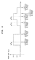
- FIG. 6 is a conceptual diagram showing a first frame rate switching pattern.
- the imaging apparatus traces back an amount of time T1 (such as one second) and changes the recording frame rate.
- T1 such as one second
- the imaging apparatus changes the recording frame rate in real time without tracing back in time.
- the imaging apparatus traces back the amount of time T1 and retroactively switches the recording frame rate to 300fps.
- the imaging apparatus switches the recording frame rate to 30fps in real time without tracing back in time.
- the imaging apparatus traces back the amount of time T1 and retroactively switches the recording frame rate to 150fps.
- the imaging apparatus When the frame rate is switched from 150fps to 300fps by user operation at time ta4, the imaging apparatus again traces back the amount of time T1 and retroactively switches the recording frame rate to 300fps.
- the imaging apparatus switches the recording frame rate to 150fps in real time without tracing back in time.
- the imaging apparatus switches the recording frame rate to 30fps in real time without tracing back in time.
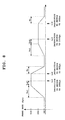
- FIG. 7 is a conceptual diagram of a second frame rate switching pattern.
- the second switching pattern is the same as the above-described first switching pattern in that, when the frame rate is switched from low-speed to high-speed by user operation, the imaging apparatus traces back a predetermined amount of time and changes the recording frame rate.
- the second switching pattern differs from the first switching pattern in that, in both of the cases where the frame rate is switched from low-speed to high-speed and where the frame rate is switched from high-speed to low-speed, the imaging apparatus gradually changes a changing speed at which the frame rate is changed and the changing speed is changed based on the amount of change in continuous shooting speed by user operation (changing period is constant).
- the imaging apparatus traces back a predetermined amount of time Ta and gradually switches the recording frame rate to 300fps.
- the imaging apparatus traces back the same predetermined amount of time Ta and gradually switches the recording frame rate from 30fps to 150fps. That is, in both cases, the changing period is the same.
- the imaging apparatus gradually switches the recording frame rate to 30fps over a predetermined time Tb.
- the imaging apparatus gradually switches the recording frame rate to 30fps over the same predetermined time Tb.
- the changing period is the same. In this way, the thinning rate is gradually changed even when the frame rate is switched to the frame rate for real speed recording (30fps), and as a result, a moving image that gradually changes from slow to real speed is obtained.
- FIG. 8 is a conceptual diagram of a third frame rate switching pattern.
- the third switching pattern is similar to the above-described second switching pattern in that the imaging apparatus traces back a predetermined amount of time and retroactively switches the recording frame rate when the frame rate is switched from low-speed to high-speed by user operation, and that the imaging apparatus gradually changes the changing speed and the changing speed is changed based on the amount of change in the continuous shooting speed by user operation (changing period is constant) in both of the cases where the frame rate is switched from low-speed to high-speed and where the frame rate is switched from high-speed to low-speed.
- the third switching pattern differs from the second switching pattern in that, when an instruction to switch the frame rate from low-speed to high-speed is given by user operation, the imaging apparatus changes the recording frame rate to high-speed at a point traced back a predetermined amount of time from the point in time where the switching instruction is given.
- the imaging apparatus traces back a predetermined amount of time (Ta1+Ta2). Then, the imaging apparatus gradually switches the recording frame rate to 300fps during the amount of time Ta1, and fixes the recording frame rate to 300fps before the amount of time Ta2. In a similar manner, when the frame rate is switched from 30fps to 150fps by user operation at time tc3, the imaging apparatus traces back the same predetermined amount of time (Ta1+Ta2). Then, after gradually switching the recording frame rate to 150fps, the imaging apparatus fixes the recording frame rate to 150fps before the amount of time Ta2. In both cases, the changing period is the same, and the frame rate is completely switched to high-speed before a predetermined amount of time elapses from the time when the switching instruction is given.
- the imaging apparatus gradually switches the recording frame rate to 30fps over the same predetermined amount of time Tb.
- FIG. 9 is a conceptual diagram of a fourth frame rate switching pattern.
- the fourth switching pattern is similar to the above-described second switching pattern in that, when the frame rate is switched from low-speed to high-speed by user operation, the imaging device traces back a predetermined amount of time and changes the recording frame rate. These are also similar in that, in both of the cases where the frame rate is switched from low-speed to high-speed and where the frame rate is switched from high-speed to low-speed, the imaging device gradually changes the changing speed.
- the fourth switching pattern differs from the second switching pattern in that the imaging apparatus changes the changing period based on the amount of change in continuous shooting speed by user operation (changing speed is constant).
- the imaging apparatus traces back a predetermined amount of time Ta3 (the amount of time actualizing a changing speed indicated by angle A°), and gradually switches the recording frame rate to 300fps.
- the imaging apparatus traces back an amount of time Ta4 actualizing the same changing speed, and gradually switches the recording frame rate to 150fps. In both cases, the changing speed is the same.
- the imaging apparatus gradually switches the recording frame rate to 30fps over a predetermined amount of time Tb1 (the amount of time actualizing a changing speed indicated by angle B°).
- Tb1 the amount of time actualizing a changing speed indicated by angle B°.
- the imaging apparatus gradually switches the recording frame rate to 30fps over an amount of time tb2 actualizing the same changing speed. In both cases, the changing speed is the same.
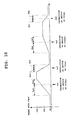
- FIG. 10 is a conceptual diagram of a fifth frame rate switching pattern.
- the changing periods before and after the switching instruction can be arbitrarily set.
- the user sets in advance the changing periods before and after the instruction to switch the frame rate from low-speed to high-speed, and the changing periods before and after the instruction to switch the frame rate from high-speed to low-speed.
- the user may set the changing periods by inputting (selecting) the real time or inputting a ratio of the changing periods before and after the instruction.
- the imaging apparatus gradually switches the recording frame rate to 300fps from a point traced back a set amount of time Ta4 until a set amount of time Ta5.
- the imaging apparatus gradually switches the recording frame rate to 150fps from a point traced back the same set amount of time Ta4 until the set amount of time Ta5.
- the imaging apparatus gradually switches the recording frame rate to 30fps from a point traced back a set amount of time Tb1 until a set amount of time Tb2.
- the imaging apparatus gradually switches the recording frame rate to 30fps from a point traced back the same a set amount of time Tb1 until the set amount of time Tb2.
- the imaging apparatus traces back a predetermined amount of time from the time when the user operation is performed, and changes the recording frame rate to high-speed. Therefore, high-speed shooting is reliably performed at the decisive moment.
- the frame buffer is provided at a stage before image compression.
- the frame buffer may be provided at a state after image compression, and the frames may be thinned-out after compression.
- the frame rates are 30fps, 150fps, and 300fps.
- the variety of frame rates to which the frame rate is changed may be increased.
- the trace back time and the frame rate at the start of recording are not limited to those described therein. Other values may be used.
- the trace back time may be increased corresponding to the changing range of the frame rate.
Landscapes
- Engineering & Computer Science (AREA)
- Multimedia (AREA)
- Signal Processing (AREA)
- Studio Devices (AREA)
- Television Signal Processing For Recording (AREA)
Abstract
Description
- The present invention relates to an imaging apparatus, a variable speed imaging method, and a recording medium storing a program thereof.
- Conventionally, an art for dynamically changing the frame rate when shooting a moving image is known (refer to, for example, Japanese Patent Application Laid-Open (Kokai) Publication No.
2002-320198 - However, in the shooting of a moving image using the conventional art, when the user changes the frame rate from 30fps to 300fps to shoot a decisive moment, the frame rate for the actual recording of the frames is changed from 30fps to 300fps at the point in time where the operation instructing the change is performed by the user. In such a technique where the frame rate is changed from 30fps to 300fps at a point in time where an operation to shoot a decisive moment is performed by the user, there is a problem that, in a case where the subject moves suddenly and a decisive moment occurs immediately before the user's operation or a case where the reaction of the user's operation is delayed, the decisive moment is filmed at 30fps and the effects of high-speed shooting is not obtained.
- The present invention has been conceived to solve the above-described problem. An object of the present invention is to provide an imaging apparatus, a variable speed imaging method, and a recording medium storing a program thereof that ensure the high-speed shooting of a decisive moment even in a case where the subject moves suddenly and a decisive moment occurs or a case where the reaction of the user's operation is delayed.
- In order to achieve the above-described object, in accordance with one aspect of the present invention, there is provided a imaging apparatus comprising: an imaging means for sequentially imaging a subject at a predetermined frame rate; a holding means for sequentially holding a plurality of frames sequentially imaged by the imaging means; a specifying means for specifying a frame rate at which frames are extracted from the holding means according to a user operation; a frame thinning means for sequentially extracting frames from the holding means at a thinning rate based on a frame rate specified by the specifying means; and a storing means for storing frames sequentially extracted by the frame thinning means as a moving image file; wherein when the specifying means specifies a frame rate change according to a user operation, the frame thinning means applies a thinning rate based on a changed frame rate from a frame traced back in time rather than when the change is specified.
- In accordance with another aspect of the present invention, there is provided a variable speed imaging method, comprising: a step for sequentially imaging a subject at a predetermined frame rate; a step for sequentially holding a plurality of frames sequentially imaged; a step for specifying a frame rate at which the frames held are extracted according to a user operation; a step for sequentially extracting the frames held at a thinning rate based on the frame rate specified; a step for storing the frames sequentially extracted as a moving image file; and a step for, when a frame rate change is specified according to a user operation, applying a thinning rate based on a changed frame rate from a frame traced back in time rather than when the change is specified.
- In accordance with another aspect of the present invention, there is provided a computer-readable storage medium having stored thereon a program for controlling operation of a moving image imaging apparatus for imaging a moving image that is executable by a computer to perform a process comprising: imaging processing for sequentially imaging a subject at a predetermined frame rate; holding processing for sequentially holding a plurality of frames sequentially imaged by the imaging processing; specifying processing for specifying a frame rate at which frames held by the holding processing are extracted according to a user operation; frame thinning processing for sequentially extracting frames held by the holding processing at a thinning rate based on a frame rate specified by the specifying processing; storing processing for storing frames sequentially extracted by the frame thinning processing as a moving image file; and processing for, when a frame rate change is specified by the specifying processing according to a user operation, applying a thinning rate based on a changed frame rate from a frame traced back in time rather than when the change is specified.
- According to the present invention, when a frame rate change is specified corresponding to a user's operation, the thinning rate based on the changed frame rate is applied from frames traced back in time rather than when the change is specified. Therefore, even in a case where the subject moves suddenly and a decisive moment occurs or a case where the reaction of the user' s operation is delayed, an advantage is acquired in that high-speed shooting can be reliably performed at the decisive moment.
- The above and further objects and novel features of the present invention will more fully appear from the following detailed description when the same is read in conjunction with the accompanying drawings. It is to be expressly understood, however, that the drawings are for the purpose of illustration only and are not intended as a definition of the limits of the invention.
-
-
FIG. 1 is a block diagram showing a configuration of an imaging apparatus (digital camera) according to an embodiment of the present invention; -
FIG. 2 is a conceptual diagram showing a configuration of a frame buffer in the imaging apparatus according to the embodiment; -
FIG. 3 is a conceptual diagram showing a configuration of frame thinning information in the imaging apparatus according to the embodiment; -
FIG. 4 is a flowchart explaining an operation performed by the imaging apparatus according to the embodiment; -
FIG. 5 is a flowchart explaining an operation performed by the imaging apparatus according to the embodiment; -
FIG. 6 is a conceptual diagram showing a first frame rate switching pattern according to the embodiment; -
FIG. 7 is a conceptual diagram showing a second frame rate switching pattern according to the embodiment; -
FIG. 8 is a conceptual diagram showing a third frame rate switching pattern according to the embodiment; -
FIG. 9 is a conceptual diagram showing a fourth frame rate switching pattern according to the embodiment; and -
FIG. 10 is a conceptual diagram showing a fifth frame rate switching pattern according to the embodiment. - The present invention will hereinafter be described in detail with reference to the preferred embodiments shown in the accompanying drawings.
-
FIG. 1 is a block diagram of a configuration of an imaging apparatus (digital camera) according to an embodiment of the present invention. - In
FIG. 1 , animage inputting section 1 includes an optical system such as a lens, an image sensor element, etc. Theimage inputting section 1 captures images at a maximum frame rate (such as 300fps) and supplies the images to aframe buffer 2. Theframe buffer 2 includes a ring buffer and sequentially buffers the images captured by theimage inputting section 1. - A continuous shooting speed
change controlling section 3 includes a ring-shaped controller provided around the periphery of a lens tube containing the lens. The continuous shooting speedchange controlling section 3 generates an instruction to change continuous shooting speed (recording frame rate) to, for example, 30fps, 150fps, or 300fps by rotating the ring-shaped controller. A framethinning setting section 4 sets frame thinning information when a current continuous shooting speed instructed is detected based on the status of the continuous shooting speedchange controlling section 3. The frame thinning information indicates, for example, from which image, and by what acquisition interval (thinning rate), the extraction of the images buffered by theframe buffer 2 is started. - In accordance with frame thinning information set by the frame
thinning setting section 4, a framethinning processing section 5 extracts, from among the images stored in theframe buffer 2, images traced back a predetermined amount of time at a predetermined acquisition interval. The framethinning processing section 5 then supplies the extracted images to an image compressingsection 6. Subsequently, theimage compressing section 6 compresses and encodes the images extracted from theframe buffer 2 by the framethinning processing section 5 using a predetermined codec. Next, theimage compressing section 6 supplies the compressed and encoded images to afile converting section 7. Then, after converting the compressed and encoded images into a moving image format file, thefile converting section 7 supplies the moving image format file to arecording medium 8. Therecording medium 8 includes an internal memory or an external memory, and stores the moving image files thereon. - Next,
FIG. 2 is a conceptual diagram of a configuration of theframe buffer 2 in the imaging apparatus according to the embodiment. - The
frame buffer 2 holds a buffer size x, a buffer head position y, a buffer frame count m, and a buffer head frame number n, and sequentially stores images or, in other words, frames captured from theimage imputing section 1. Every time a frame is generated in theimage inputting section 1, theframe buffer 2 stores a pointer pointing to the frame, namely the buffer head position (currently targeted position) y. The size x of theframe buffer 2 corresponds to the number of frames equivalent to more than the amount of time for changing the frame rates of frames traced back from the point in time at which the continuous shooting speed change control is performed by user operation. - Next,
FIG. 3 is a conceptual diagram of a configuration of the frame thinning information in the imaging apparatus according to the embodiment. - The frame thinning information is stored in a ring buffer and includes an information size s, an information head position (currently targeted position) t, and an information amount j. In addition, a switching frame number, and an acquisition interval that is used starting from this switching frame number are sequentially stored as part of the frame thinning information every time continuous shooting speed change control is performed by user operation. The switching frame number indicates from which image the change of the acquisition interval is applied. The acquisition interval indicates an interval at which frames are acquired from the
frame buffer 2. For example, when the maximum frame rate is "1" (no thinning) and the frame rate is 1/10th, the acquisition interval is "10". The information size s is required to be a size greater than the number of times the change control can be performed within the trace back time so that control information recordings are not missed. - In the example in
FIG. 3 , frame numbers "1" to "1499" are acquired at a frame rate of 1/10th. Frame numbers "1500" to "2999" are acquired at a frame rate of 1/1 (maximum frame rate). Frame numbers "3000" to "4499" are acquired at a frame rate of 1/2. Frame number "4500" and subsequent frames are acquired at a frame rate of 1/10th. - Next, operations of the imaging apparatus according to the above-described embodiment will be described.
-
FIG. 4 andFIG. 5 are flowcharts (operation programs) explaining the operations of the imaging apparatus according to the embodiment. - Note that a recording frame rate of this imaging apparatus can be switched to 30fps, 150 fps, and 300fps based on the user' s operation of the continuous shooting speed
change controlling section 3. In addition, images (frames) can be stored in theframe buffer 2 at 300fps. When frames are being recorded at 30fps, the frames are thinned-out to 1/10th and extracted. When frames are being recorded at 150fps, the frames are thinned-out to 1/2 and extracted. The extracted frames are compressed and saved as a file. The frame rate for reproduction is 30fps, and recording at 30fps is the actual speed recording. The trace back time for changing the frame rate is one second, based on user operation. - First, as an initial setting, the imaging apparatus sets the recording frame rate to 30fps, the information head position t in the frame thinning information to "1", and the acquisition interval to "10" (=1/10th) (Step S10). Next, the imaging apparatus starts shooting a moving image and waits for an event to occur (Step S12). This event occurs every time images corresponding to a single frame are captured (imaged) from the
image inputting section 1. Even while images are not captured from theimage inputting section 1, this event occurs at every predetermined amount of time. A reason for this is to allow remaining frames stored in theframe buffer 2 to be processed after an instruction is given to terminate moving image shooting. Then, when the event occurs, the imaging apparatus judges whether or not a frame has been captured from the image inputting section 1 (Step S14). When judged that a frame has been captured, the imaging apparatus stores the frame in the frame buffer 2 (Step S16). - On the other hand, when judged that a frame has not been captured, or after the frame is stored in the
frame buffer 2, the imaging apparatus judges whether or not frames captured one second earlier have been stored in the frame buffer 2 (Step S18). In other words, the imaging apparatus judges whether or not frames that should be recorded have been stored in theframe buffer 2. When judged that frames captured one second earlier have not been stored in theframe buffer 2, the imaging apparatus proceeds directly to Step S30 because no frames that should be captured are present. - On the other hand, when judged that frames captured one second earlier have been stored in the
frame buffer 2, at Step S20 to Step S28, the imaging apparatus sequentially extracts the frames stored in theframe buffer 2 at the acquisition interval, performs image compression, and saves them as a file. When the frame number of a frame being extracted is equal to or more than the switching frame number in the frame thinning information, an operation for changing the acquisition interval to a value corresponding to the next switching frame number is performed. - First, the imaging apparatus acquires the next frame from the frame buffer 2 (Step S20), and after compressing the acquired frame, saves the compressed frame as a file (Step S22). Then, the imaging apparatus judges whether or not the frame number of the frame is equal to or more than the switching frame number in the frame thinning information to be referenced next (Step S24). When the buffer head position y in the
frame buffer 2 is equal to or more than the next switch frame number, the imaging apparatus is required to increment an information reference position (information head position t) of the switching frame number in the frame thinning information by 1. - On the other hand, when the frame number is not equal to or more than the switching frame number in the frame thinning information, the imaging apparatus is not required to increment the information reference position of the switching frame number in the frame thinning information by 1. Therefore, the imaging apparatus performs an update in accordance with the acquisition interval at the same information reference position as up to this point (Step S28). For example, when the current frame number is "1491", the switching frame number in the frame thinning information to be referenced next is "1500", and the current acquisition interval is "10", the frame number to be acquired next is "1501".
- On the other hand, when the frame number is equal to or more than the switching frame number in the frame thinning information to be referenced next, the imaging apparatus increments the information head position t by 1 (Step S26) and updates the frame number of the frame to be acquired next in accordance with the acquisition interval at the new information reference position (Step S28). For example, when the current frame number is "1501", the switching frame number in the frame thinning information to be referenced next is "3000", and the current acquisition interval is "1" (see the bottommost row in
FIG. 3 ), the frame number to be acquired next is "1502". - Next, the imaging apparatus judges whether or not a frame rate changing operation has been made by user operation (Step S30). When judged that the frame rate changing operation has been made by user operation, the imaging apparatus updates the frame thinning information at subsequent Step S32 to Step S38.
- First, the imaging apparatus sets the switching frame number in the frame thinning information to the last frame number in the frame buffer 2 (the latest frame capturing position) (Step S32). For example, when the last frame number in the
frame buffer 2 is "1800", the switching frame number in the new frame thinning information is "1800". Next, the imaging apparatus judges whether or not the frame rate changing operation has changed the frame rate to a faster frame rate (Step S34). When judged that the frame rate changing operation has changed the frame rate to a faster frame rate, for example, when judged that the frame rate has been changed from 30fps to 300fps, the imaging apparatus sets the switching frame number in the frame thinning information to "1500" captured one second earlier (=1800-300) (Step S36) sets the acquisition interval to "1", and updates the frame thinning information (Step S38). - When frames correspond to one second are not found in the frame buffer 2 (in other words, when the last frame number is 300 or less), the imaging apparatus sets the head frame number in the
frame buffer 2 to the switching frame number in the frame thinning information. When the frame rate is changed from 30fps to 150fps or from 150fps to 300fps, as in the case where the frame rate is changed from 30fps to 300fps, the imaging apparatus sets the switching frame number in the frame thinning information to "1500" captured one second earlier (=1800-300) and sets the acquisition intervals to "2" and "1", respectively. - On the other hand, when judged that the frame rate changing operation has not changed the frame rate to a faster frame rate, for example, when judged that the frame rate has been changed from 300fps to 150fps or 30fps, or from 150fps to 30fps, the imaging apparatus sets the switching frame number in the frame thinning information to the last frame number "1800" in the
frame buffer 2 as it is, and after setting the acquisition interval to "1" or "10", updates the frame thinning information (Step S38). Here, the imaging apparatus uses the last frame number in theframe buffer 2 as it is to change the frame rate at the point in time where the user operation to change the frame rate is performed so that the decisive moment is not retroactively shot at 30fps. - Next, after the frame thinning information updating processing accompanying the frame rate changing operation performed by user operation, or when judged that the frame rate changing operation by user operation has not been performed, the imaging apparatus performs another record processing (Step S40) and judges whether or not recording is continuing (Step S42). When recording is continuing, the imaging apparatus returns to Step S12 and repeats the above-described process.
- On the other hand, when recording is completed, the imaging apparatus judges whether or not any frames remain in the frame buffer 2 (Step S44). When there are frames in the
frame buffer 2, the imaging apparatus returns to Step S20 and repeats the above-described processing. On the other hand, when there are no frames in theframe buffer 2, the imaging apparatus terminates the record processing. - Next, examples of a frame rate switching pattern performed by the imaging apparatus according to the embodiment will be described.
-
FIG. 6 is a conceptual diagram showing a first frame rate switching pattern. In the first switching pattern, when the frame rate is switched from low-speed to high-speed, for example, 30fps to 150fps or 300fps, or 150fps to 300fps by user operation, the imaging apparatus traces back an amount of time T1 (such as one second) and changes the recording frame rate. On the other hand, when the frame rate is switched from high-speed to low-speed, for example, 300fps to 150fps or 30fps, or 150fps to 30fps, the imaging apparatus changes the recording frame rate in real time without tracing back in time. - As shown in
FIG. 6 , first, when the frame rate is switched to 300fps by user operation while shooting at 30fps at time ta1, the imaging apparatus traces back the amount of time T1 and retroactively switches the recording frame rate to 300fps. Next, when the frame rate is switched from 300fps to 30fps by user operation at time ta2, the imaging apparatus switches the recording frame rate to 30fps in real time without tracing back in time. Next, when the frame rate is switched from 30fps to 150fps by user operation at time ta3, the imaging apparatus traces back the amount of time T1 and retroactively switches the recording frame rate to 150fps. - When the frame rate is switched from 150fps to 300fps by user operation at time ta4, the imaging apparatus again traces back the amount of time T1 and retroactively switches the recording frame rate to 300fps. Next, when the frame rate is switched from 300fps to 150fps by user operation at time ta5, the imaging apparatus switches the recording frame rate to 150fps in real time without tracing back in time. When the frame rate is switched from 150fps to 30fps at time ta6, the imaging apparatus switches the recording frame rate to 30fps in real time without tracing back in time.
-
FIG. 7 is a conceptual diagram of a second frame rate switching pattern. The second switching pattern is the same as the above-described first switching pattern in that, when the frame rate is switched from low-speed to high-speed by user operation, the imaging apparatus traces back a predetermined amount of time and changes the recording frame rate. However, the second switching pattern differs from the first switching pattern in that, in both of the cases where the frame rate is switched from low-speed to high-speed and where the frame rate is switched from high-speed to low-speed, the imaging apparatus gradually changes a changing speed at which the frame rate is changed and the changing speed is changed based on the amount of change in continuous shooting speed by user operation (changing period is constant). - As shown in
FIG. 7 , first, when the frame rate is switched from 30fps to 300fps by user operation at time tb1, the imaging apparatus traces back a predetermined amount of time Ta and gradually switches the recording frame rate to 300fps. In a similar manner, when the frame rate is switched from 30fps to 150fps by user operation at time tb3, the imaging apparatus traces back the same predetermined amount of time Ta and gradually switches the recording frame rate from 30fps to 150fps. That is, in both cases, the changing period is the same. - On the other hand, when the frame rate is switched from 300fps to 30fps by user operation at time tb2, the imaging apparatus gradually switches the recording frame rate to 30fps over a predetermined time Tb. In a similar manner, when the frame rate is switched from 150fps to 30fps by user operation at time tb4, the imaging apparatus gradually switches the recording frame rate to 30fps over the same predetermined time Tb. In both cases, the changing period is the same. In this way, the thinning rate is gradually changed even when the frame rate is switched to the frame rate for real speed recording (30fps), and as a result, a moving image that gradually changes from slow to real speed is obtained.
- Next,
FIG. 8 is a conceptual diagram of a third frame rate switching pattern. The third switching pattern is similar to the above-described second switching pattern in that the imaging apparatus traces back a predetermined amount of time and retroactively switches the recording frame rate when the frame rate is switched from low-speed to high-speed by user operation, and that the imaging apparatus gradually changes the changing speed and the changing speed is changed based on the amount of change in the continuous shooting speed by user operation (changing period is constant) in both of the cases where the frame rate is switched from low-speed to high-speed and where the frame rate is switched from high-speed to low-speed. However, the third switching pattern differs from the second switching pattern in that, when an instruction to switch the frame rate from low-speed to high-speed is given by user operation, the imaging apparatus changes the recording frame rate to high-speed at a point traced back a predetermined amount of time from the point in time where the switching instruction is given. - As shown in
FIG. 8 , first, when the frame rate is switched from 30fps to 300fps by user operation at time tc1, the imaging apparatus traces back a predetermined amount of time (Ta1+Ta2). Then, the imaging apparatus gradually switches the recording frame rate to 300fps during the amount of time Ta1, and fixes the recording frame rate to 300fps before the amount of time Ta2. In a similar manner, when the frame rate is switched from 30fps to 150fps by user operation at time tc3, the imaging apparatus traces back the same predetermined amount of time (Ta1+Ta2). Then, after gradually switching the recording frame rate to 150fps, the imaging apparatus fixes the recording frame rate to 150fps before the amount of time Ta2. In both cases, the changing period is the same, and the frame rate is completely switched to high-speed before a predetermined amount of time elapses from the time when the switching instruction is given. - On the other hand, in a manner similar to the above-described second switching pattern, when the frame rate is switched by user operation from 300fps to 30fps or from 150fps to 30fps, at time tc2 and time tc4, respectively, the imaging apparatus gradually switches the recording frame rate to 30fps over the same predetermined amount of time Tb.
- Next,
FIG. 9 is a conceptual diagram of a fourth frame rate switching pattern. The fourth switching pattern is similar to the above-described second switching pattern in that, when the frame rate is switched from low-speed to high-speed by user operation, the imaging device traces back a predetermined amount of time and changes the recording frame rate. These are also similar in that, in both of the cases where the frame rate is switched from low-speed to high-speed and where the frame rate is switched from high-speed to low-speed, the imaging device gradually changes the changing speed. However, the fourth switching pattern differs from the second switching pattern in that the imaging apparatus changes the changing period based on the amount of change in continuous shooting speed by user operation (changing speed is constant). - As shown in
FIG. 9 , first, when the frame rate is switched from 30fps to 300fps by user operation at time td1, the imaging apparatus traces back a predetermined amount of time Ta3 (the amount of time actualizing a changing speed indicated by angle A°), and gradually switches the recording frame rate to 300fps. In a similar manner, when the frame rate is switched from 30fps to 150fps by user operation at time td3, the imaging apparatus traces back an amount of time Ta4 actualizing the same changing speed, and gradually switches the recording frame rate to 150fps. In both cases, the changing speed is the same. - On the other hand, when the frame rate is switched from 300fps to 30fps by user operation at time td2, the imaging apparatus gradually switches the recording frame rate to 30fps over a predetermined amount of time Tb1 (the amount of time actualizing a changing speed indicated by angle B°). In a similar manner, when the frame rate is switched from 150fps to 30fps by user operation at time td4, the imaging apparatus gradually switches the recording frame rate to 30fps over an amount of time tb2 actualizing the same changing speed. In both cases, the changing speed is the same.
- Next,
FIG. 10 is a conceptual diagram of a fifth frame rate switching pattern. In the fifth switching pattern, the changing periods before and after the switching instruction can be arbitrarily set. The user sets in advance the changing periods before and after the instruction to switch the frame rate from low-speed to high-speed, and the changing periods before and after the instruction to switch the frame rate from high-speed to low-speed. The user may set the changing periods by inputting (selecting) the real time or inputting a ratio of the changing periods before and after the instruction. - As shown in
FIG. 10 , first, when the frame rate is switched from 30fps to 300fps by user operation at time te1, the imaging apparatus gradually switches the recording frame rate to 300fps from a point traced back a set amount of time Ta4 until a set amount of time Ta5. In a similar manner, when the frame rate is switched from 30fps to 150fps by user operation at time te3, the imaging apparatus gradually switches the recording frame rate to 150fps from a point traced back the same set amount of time Ta4 until the set amount of time Ta5. - On the other hand, when the frame rate is switched from 300fps to 30fps by user operation at time te2, the imaging apparatus gradually switches the recording frame rate to 30fps from a point traced back a set amount of time Tb1 until a set amount of time Tb2. In a similar manner, when the frame rate is switched from 150fps to 30fps by user operation at time te4, the imaging apparatus gradually switches the recording frame rate to 30fps from a point traced back the same a set amount of time Tb1 until the set amount of time Tb2.
- According to the above-described embodiments, when continuous shooting speed (recording frame rate) is changed from low-speed to high-speed by user operation, the imaging apparatus traces back a predetermined amount of time from the time when the user operation is performed, and changes the recording frame rate to high-speed. Therefore, high-speed shooting is reliably performed at the decisive moment.
- Note that, according to the above-described embodiments, the frame buffer is provided at a stage before image compression. However, the frame buffer may be provided at a state after image compression, and the frames may be thinned-out after compression.
- In addition, according to the above-described embodiments, the frame rates are 30fps, 150fps, and 300fps. However, the variety of frame rates to which the frame rate is changed may be increased.
- Moreover, in the above-described embodiments, the trace back time and the frame rate at the start of recording are not limited to those described therein. Other values may be used.
- Furthermore, in the above-described embodiments, when the frame rate is changed to high-speed, the trace back time may be increased corresponding to the changing range of the frame rate.
- Still further, in the above-described embodiments, explanation was given on the case of moving images. However, these moving images may be moving images with audio.
Claims (13)
- An imaging apparatus comprising:an imaging means (1) for sequentially imaging a subject at a predetermined frame rate;a holding means (2) for sequentially holding a plurality of frames sequentially imaged by the imaging means;a specifying means (3) for specifying a frame rate at which frames are extracted from the holding means according to a user operation;a frame thinning means (4 and 5) for sequentially extracting frames from the holding means at a thinning rate based on the frame rate specified by the specifying means; anda storing means (6 to 8) for storing frames sequentially extracted by the frame thinning means as a moving image file;wherein when the specifying means (3) specifies a frame rate change according to a user operation, the frame thinning means (4 and 5) applies a thinning rate based on a changed frame rate from a frame traced back in time rather than when a change is specified.
- The imaging apparatus according to claim 1, wherein the frame thinning means (4 and 5) applies the thinning rate based on the changed frame rate from a frame imaged by the imaging means (1) a predetermined amount of time earlier than when the frame rate change is specified, and held by the holding means (2) ; and
wherein the holding means (2) simultaneously holds a plurality of frames including at least frames from the frame imaged the predetermined amount of time earlier by the imaging means (1) to a most recently imaged frame. - The imaging apparatus according to claim 2, wherein the frame thinning means (4 and 5) performs processing for extracting a frame from the holding means (2) at a timing delayed by the predetermined amount of time or more from a timing at which the frame is imaged by the imaging means (1).
- The imaging apparatus according to claim 3, wherein the frame thinning means (4 and 5) continues, even after the imaging means (1) completes imaging of a plurality of frames for a moving image, the processing for extracting a frame until all frames held in the holding means (2) are processed.
- The imaging apparatus according to claim 1, wherein the imaging means continues, regardless of the frame rate change by the specifying means (3), imaging at a frame rate that is equal to or faster than the fastest frame rate specified by the specifying means (3).
- The imaging apparatus according claim 1, wherein when a frame rate is changed by the specifying means (3) according to the user operation, the frame thinning means (4 and 5) gradually changes, between a frame traced back in time from the changing point and a frame at the changing point, a thinning rate from a thinning rate based on the frame rate before the change to a thinning rate based on a frame rate after the change.
- The imaging apparatus according to claim 1, wherein when a frame rate is changed by the specifying means (3) according to the user operation, the frame thinning means (4 and 5) gradually changes, from a frame traced back in time from the changing point, a thinning rate from a thinning rate based on the frame rate before the change to a thinning rate based on a frame rate after the change such that the thinning rate based on the frame rate after the change is achieved at a frame captured a predetermined amount of time earlier than the changing point.
- The imaging apparatus according to claim 6, wherein the frame thinning means (4 and 5) sets trace back time from the changing point to a fixed amount of time regardless of whether the frame rate changed by the specifying means (3) according to the user operation is faster or slower.
- The imaging apparatus according to claim 6, wherein the frame thinning means (4 and 5) sets a changing speed for changing the thinning rate between the frame traced back in time from the changing point and the frame at the changing point to a fixed speed regardless of whether the frame rate changed by the specifying means (3) according to the user operation is faster or slower.
- The imaging apparatus according to claim 6, further comprising:a setting means for setting, when the frame rate is changed by the specifying means (3) according to the user operation, a starting frame and an ending frame to which the thinning rate based on the changed frame rate is applied by the frame thinning means.
- The imaging apparatus according to claim 1, wherein when a frame rate is changed from a low rate to a high rate by the specifying means (3) according to the user operation, the frame thinning means applies a thinning rate based on a changed frame rate from a frame traced back in time from the changing point, while when a frame rate is changed from a high rate to a low rate by the specifying means (3) according to the user operation, the frame thinning means applies a thinning rate based on a changed frame rate from a frame at the changing point.
- A variable speed imaging method, comprising:a step for sequentially imaging a subject at a predetermined frame rate (S14);a step for sequentially holding a plurality of frames sequentially imaged (S16);a step for specifying a frame rate at which the frames held are extracted according to a user operation (S30);a step for sequentially extracting the frames held at a thinning rate based on the frame rate specified(S20);a step for storing the frames sequentially extracted as a moving image file (S22); anda step for, when a frame rate change is specified according to a user operation, applying a thinning rate based on a changed frame rate from a frame traced back in time rather than when the change is specified (S36).
- A computer-readable storage medium having stored thereon a program for controlling operation of a moving image imaging apparatus for imaging a moving image that is executable by a computer to perform a process comprising:imaging processing for sequentially imaging a subject at a predetermined frame rate (S14);holding processing for sequentially holding a plurality of frames sequentially imaged by the imaging processing (S16);specifying processing for specifying a frame rate at which frames held by the holding processing are extracted according to a user operation (S30);frame thinning processing for sequentially extracting frames held by the holding processing at a thinning rate based on a frame rate specified by the specifying processing (S20);storing processing for storing frames sequentially extracted by the frame thinning processing as a moving image file (S22); andprocessing for, when a frame rate change is specified by the specifying processing according to a user operation, applying a thinning rate based on a changed frame rate from a frame traced back in time rather than when the change is specified (S36).
Applications Claiming Priority (1)
| Application Number | Priority Date | Filing Date | Title |
|---|---|---|---|
| JP2008253745A JP2010087778A (en) | 2008-09-30 | 2008-09-30 | Imaging apparatus, variable speed imaging method, and program |
Publications (3)
| Publication Number | Publication Date |
|---|---|
| EP2182719A2 true EP2182719A2 (en) | 2010-05-05 |
| EP2182719A3 EP2182719A3 (en) | 2010-05-26 |
| EP2182719B1 EP2182719B1 (en) | 2011-11-09 |
Family
ID=42041652
Family Applications (1)
| Application Number | Title | Priority Date | Filing Date |
|---|---|---|---|
| EP09170377A Not-in-force EP2182719B1 (en) | 2008-09-30 | 2009-09-16 | Imaging apparatus, variable speed imaging method, and recording medium storing program thereof |
Country Status (7)
| Country | Link |
|---|---|
| US (1) | US8314856B2 (en) |
| EP (1) | EP2182719B1 (en) |
| JP (1) | JP2010087778A (en) |
| KR (1) | KR101069623B1 (en) |
| CN (1) | CN101815168B (en) |
| AT (1) | ATE533303T1 (en) |
| TW (1) | TWI380683B (en) |
Cited By (1)
| Publication number | Priority date | Publication date | Assignee | Title |
|---|---|---|---|---|
| CN101895690A (en) * | 2010-08-23 | 2010-11-24 | 天津三星光电子有限公司 | Multiple time-delay continuous shooting method for digital camera |
Families Citing this family (18)
| Publication number | Priority date | Publication date | Assignee | Title |
|---|---|---|---|---|
| JP5414357B2 (en) | 2009-05-20 | 2014-02-12 | キヤノン株式会社 | Imaging device and playback device |
| JP5824972B2 (en) * | 2010-11-10 | 2015-12-02 | カシオ計算機株式会社 | Imaging apparatus, frame rate control apparatus, imaging control method, and program |
| JP5768381B2 (en) | 2011-01-20 | 2015-08-26 | カシオ計算機株式会社 | Moving image processing apparatus, moving image processing method, and program |
| CN104469126B (en) * | 2013-09-18 | 2019-05-31 | 联想(北京)有限公司 | Continuous shooting method, device and terminal |
| JP6350863B2 (en) * | 2013-12-20 | 2018-07-04 | ソニー株式会社 | Imaging device, imaging device, and electronic device |
| JP5817858B2 (en) * | 2014-01-30 | 2015-11-18 | カシオ計算機株式会社 | Image processing apparatus, image processing method, and program |
| JP2015186235A (en) * | 2014-03-26 | 2015-10-22 | ソニー株式会社 | Image sensor and electronic device |
| CN104978392B (en) * | 2014-04-03 | 2018-12-28 | 卡西欧计算机株式会社 | Export the content output apparatus of content |
| JP6341815B2 (en) * | 2014-09-08 | 2018-06-13 | キヤノン株式会社 | Imaging device, control method thereof, and program |
| CN106303188A (en) * | 2015-05-18 | 2017-01-04 | 大通电子股份有限公司 | Film production method |
| CN106375646B (en) * | 2015-07-21 | 2020-01-10 | 腾讯科技(深圳)有限公司 | Information processing method and terminal |
| KR102657050B1 (en) | 2017-01-25 | 2024-04-15 | 삼성전자주식회사 | Electronic device and method for capturing an image in the electronic device |
| CN107155068A (en) * | 2017-07-11 | 2017-09-12 | 上海青橙实业有限公司 | Mobile terminal and the method and apparatus for video capture |
| CN109429067B (en) * | 2017-08-31 | 2022-10-25 | 腾讯科技(深圳)有限公司 | Dynamic picture compression method and device, computer equipment and storage medium |
| JP2019086701A (en) * | 2017-11-08 | 2019-06-06 | キヤノン株式会社 | Imaging control apparatus and control method thereof |
| RU2716005C2 (en) * | 2018-06-29 | 2020-03-05 | Закрытое акционерное общество "МНИТИ" (ЗАО "МНИТИ") | Video tracking method with improved dynamic characteristics and device for implementation thereof |
| CN109068052B (en) * | 2018-07-24 | 2020-11-10 | 努比亚技术有限公司 | Video shooting method, mobile terminal and computer readable storage medium |
| CN116245865A (en) * | 2023-03-20 | 2023-06-09 | 鸿湖万联(江苏)科技发展有限公司 | Image quality detection method, device, electronic equipment and storage medium |
Citations (1)
| Publication number | Priority date | Publication date | Assignee | Title |
|---|---|---|---|---|
| JP2002320198A (en) | 2001-04-23 | 2002-10-31 | Casio Comput Co Ltd | Video recording device |
Family Cites Families (19)
| Publication number | Priority date | Publication date | Assignee | Title |
|---|---|---|---|---|
| US6337928B1 (en) * | 1996-08-26 | 2002-01-08 | Canon Kabushiki Kaisha | Image transmission apparatus and method therefor |
| US7545434B2 (en) | 2002-02-04 | 2009-06-09 | Hewlett-Packard Development Company, L.P. | Video camera with variable image capture rate and related methodology |
| US20030189647A1 (en) * | 2002-04-05 | 2003-10-09 | Kang Beng Hong Alex | Method of taking pictures |
| JP2004304418A (en) * | 2003-03-31 | 2004-10-28 | Minolta Co Ltd | Camera |
| JP2005241787A (en) * | 2004-02-25 | 2005-09-08 | Victor Co Of Japan Ltd | Picture display apparatus |
| JP2005348258A (en) * | 2004-06-04 | 2005-12-15 | Canon Inc | Imaging apparatus and method, program, and storage medium |
| JP4366277B2 (en) * | 2004-09-21 | 2009-11-18 | キヤノン株式会社 | Imaging apparatus and control method thereof |
| JP2006174188A (en) * | 2004-12-17 | 2006-06-29 | Casio Comput Co Ltd | Movie recording apparatus and movie shooting method |
| JP4537266B2 (en) * | 2005-06-16 | 2010-09-01 | キヤノン株式会社 | Recording apparatus and reproducing apparatus |
| JP4616135B2 (en) * | 2005-09-21 | 2011-01-19 | オリンパス株式会社 | Imaging apparatus and image recording apparatus |
| EP1956839A4 (en) * | 2005-11-29 | 2010-03-17 | Pioneer Corp | Recording device, reproduction device, recording method, recording program, and computer-readable recording medium |
| JP4847165B2 (en) * | 2006-03-09 | 2011-12-28 | 株式会社日立製作所 | Video recording / reproducing method and video recording / reproducing apparatus |
| TWI394437B (en) * | 2006-09-28 | 2013-04-21 | Casio Computer Co Ltd | Photographic device, recording medium for recording computer program, and photography control method |
| JP2008099110A (en) * | 2006-10-13 | 2008-04-24 | Olympus Corp | Imaging apparatus |
| JPWO2008050806A1 (en) * | 2006-10-24 | 2010-02-25 | ソニー株式会社 | Imaging device and playback control device |
| JP4798506B2 (en) * | 2007-03-12 | 2011-10-19 | カシオ計算機株式会社 | Imaging apparatus and program thereof |
| JP4353253B2 (en) * | 2007-01-31 | 2009-10-28 | ソニー株式会社 | FRAME RATE CONTROL DEVICE, FRAME RATE CONTROL METHOD, RECORDING DEVICE, AND IMAGING DEVICE |
| WO2008099685A1 (en) * | 2007-02-01 | 2008-08-21 | Sony Corporation | Image reproducing apparatus, image reproducing method, imaging apparatus and method for controlling the imaging apparatus |
| JP4906668B2 (en) * | 2007-10-18 | 2012-03-28 | 株式会社キーエンス | High-speed photographing apparatus, high-speed photographing apparatus control method, and computer program |
-
2008
- 2008-09-30 JP JP2008253745A patent/JP2010087778A/en active Pending
-
2009
- 2009-09-16 AT AT09170377T patent/ATE533303T1/en active
- 2009-09-16 EP EP09170377A patent/EP2182719B1/en not_active Not-in-force
- 2009-09-28 CN CN2009102584444A patent/CN101815168B/en active Active
- 2009-09-28 KR KR1020090091628A patent/KR101069623B1/en not_active Expired - Fee Related
- 2009-09-29 TW TW098132822A patent/TWI380683B/en not_active IP Right Cessation
- 2009-09-30 US US12/570,200 patent/US8314856B2/en active Active
Patent Citations (1)
| Publication number | Priority date | Publication date | Assignee | Title |
|---|---|---|---|---|
| JP2002320198A (en) | 2001-04-23 | 2002-10-31 | Casio Comput Co Ltd | Video recording device |
Cited By (1)
| Publication number | Priority date | Publication date | Assignee | Title |
|---|---|---|---|---|
| CN101895690A (en) * | 2010-08-23 | 2010-11-24 | 天津三星光电子有限公司 | Multiple time-delay continuous shooting method for digital camera |
Also Published As
| Publication number | Publication date |
|---|---|
| ATE533303T1 (en) | 2011-11-15 |
| TWI380683B (en) | 2012-12-21 |
| TW201029454A (en) | 2010-08-01 |
| US20100079620A1 (en) | 2010-04-01 |
| EP2182719A3 (en) | 2010-05-26 |
| KR20100036964A (en) | 2010-04-08 |
| CN101815168B (en) | 2012-05-09 |
| EP2182719B1 (en) | 2011-11-09 |
| KR101069623B1 (en) | 2011-10-05 |
| JP2010087778A (en) | 2010-04-15 |
| CN101815168A (en) | 2010-08-25 |
| US8314856B2 (en) | 2012-11-20 |
Similar Documents
| Publication | Publication Date | Title |
|---|---|---|
| EP2182719B1 (en) | Imaging apparatus, variable speed imaging method, and recording medium storing program thereof | |
| KR101467875B1 (en) | Digital camera capable of variable frame rate setting and control method thereof | |
| US8294779B2 (en) | Image sensing apparatus and storage medium | |
| US8488043B2 (en) | Imaging apparatus, recording medium for recording a computer program, and imaging control method | |
| US7787019B2 (en) | Camera and shooting control method therefor | |
| US9743000B2 (en) | Moving image processing apparatus, imaging apparatus, and moving image processing method | |
| CN102611865A (en) | Apparatus and method for processing moving image data | |
| US20060132636A1 (en) | Moving-image recording device for recording moving image | |
| US20160330372A1 (en) | Imaging device | |
| KR101433119B1 (en) | Image processing device for generating composite image having predetermined aspect ratio | |
| CN104378547A (en) | Imaging apparatus, image processing device, image processing method, and program | |
| US8605170B2 (en) | Imaging device, method of processing captured image signal and computer program | |
| US10032482B2 (en) | Moving image generating apparatus, moving image generating method and storage medium | |
| US9066011B2 (en) | Image synthesizing apparatus that synthesizes multiple images to obtain moving image, control method therefor, and storage medium | |
| JP2013081101A (en) | Image processing apparatus, imaging apparatus, and program | |
| JP2008306334A (en) | Movie file generation method and movie shooting apparatus using the same | |
| US20070279517A1 (en) | Method for recording image and image pickup apparatus | |
| US20110193991A1 (en) | Recording apparatus, imaging and recording apparatus, recording method, and program | |
| US8401365B2 (en) | Recording apparatus, imaging and recording apparatus, recording method, and program | |
| JP2015061235A (en) | Image processing apparatus, image processing method, and program | |
| JP2012222526A (en) | Imaging apparatus, method, and program | |
| JP5915009B2 (en) | Image processing apparatus, electronic camera, image processing method, program, and recording medium | |
| HK1171594A (en) | Motion image processing apparatus and motion image processing method for processing motion image data | |
| HK1136727B (en) | Image sensing apparatus and image control method |
Legal Events
| Date | Code | Title | Description |
|---|---|---|---|
| PUAI | Public reference made under article 153(3) epc to a published international application that has entered the european phase |
Free format text: ORIGINAL CODE: 0009012 |
|
| PUAL | Search report despatched |
Free format text: ORIGINAL CODE: 0009013 |
|
| 17P | Request for examination filed |
Effective date: 20090916 |
|
| AK | Designated contracting states |
Kind code of ref document: A2 Designated state(s): AT BE BG CH CY CZ DE DK EE ES FI FR GB GR HR HU IE IS IT LI LT LU LV MC MK MT NL NO PL PT RO SE SI SK SM TR |
|
| AX | Request for extension of the european patent |
Extension state: AL BA RS |
|
| AK | Designated contracting states |
Kind code of ref document: A3 Designated state(s): AT BE BG CH CY CZ DE DK EE ES FI FR GB GR HR HU IE IS IT LI LT LU LV MC MK MT NL NO PL PT RO SE SI SK SM TR |
|
| AX | Request for extension of the european patent |
Extension state: AL BA RS |
|
| RIC1 | Information provided on ipc code assigned before grant |
Ipc: H04N 5/77 20060101ALI20100419BHEP Ipc: H04N 5/232 20060101AFI20100330BHEP |
|
| REG | Reference to a national code |
Ref country code: DE Ref legal event code: R079 Ref document number: 602009003565 Country of ref document: DE Free format text: PREVIOUS MAIN CLASS: H04N0005232000 Ipc: H04N0005770000 |
|
| GRAP | Despatch of communication of intention to grant a patent |
Free format text: ORIGINAL CODE: EPIDOSNIGR1 |
|
| RIC1 | Information provided on ipc code assigned before grant |
Ipc: H04N 5/77 20060101AFI20110406BHEP Ipc: H04N 5/232 20060101ALI20110406BHEP |
|
| GRAS | Grant fee paid |
Free format text: ORIGINAL CODE: EPIDOSNIGR3 |
|
| GRAA | (expected) grant |
Free format text: ORIGINAL CODE: 0009210 |
|
| AK | Designated contracting states |
Kind code of ref document: B1 Designated state(s): AT BE BG CH CY CZ DE DK EE ES FI FR GB GR HR HU IE IS IT LI LT LU LV MC MK MT NL NO PL PT RO SE SI SK SM TR |
|
| REG | Reference to a national code |
Ref country code: GB Ref legal event code: FG4D |
|
| REG | Reference to a national code |
Ref country code: CH Ref legal event code: EP |
|
| REG | Reference to a national code |
Ref country code: IE Ref legal event code: FG4D |
|
| REG | Reference to a national code |
Ref country code: DE Ref legal event code: R096 Ref document number: 602009003565 Country of ref document: DE Effective date: 20120209 |
|
| REG | Reference to a national code |
Ref country code: NL Ref legal event code: VDEP Effective date: 20111109 |
|
| LTIE | Lt: invalidation of european patent or patent extension |
Effective date: 20111109 |
|
| PG25 | Lapsed in a contracting state [announced via postgrant information from national office to epo] |
Ref country code: IS Free format text: LAPSE BECAUSE OF FAILURE TO SUBMIT A TRANSLATION OF THE DESCRIPTION OR TO PAY THE FEE WITHIN THE PRESCRIBED TIME-LIMIT Effective date: 20120309 Ref country code: NO Free format text: LAPSE BECAUSE OF FAILURE TO SUBMIT A TRANSLATION OF THE DESCRIPTION OR TO PAY THE FEE WITHIN THE PRESCRIBED TIME-LIMIT Effective date: 20120209 Ref country code: LT Free format text: LAPSE BECAUSE OF FAILURE TO SUBMIT A TRANSLATION OF THE DESCRIPTION OR TO PAY THE FEE WITHIN THE PRESCRIBED TIME-LIMIT Effective date: 20111109 |
|
| PG25 | Lapsed in a contracting state [announced via postgrant information from national office to epo] |
Ref country code: BE Free format text: LAPSE BECAUSE OF FAILURE TO SUBMIT A TRANSLATION OF THE DESCRIPTION OR TO PAY THE FEE WITHIN THE PRESCRIBED TIME-LIMIT Effective date: 20111109 Ref country code: PT Free format text: LAPSE BECAUSE OF FAILURE TO SUBMIT A TRANSLATION OF THE DESCRIPTION OR TO PAY THE FEE WITHIN THE PRESCRIBED TIME-LIMIT Effective date: 20120309 Ref country code: GR Free format text: LAPSE BECAUSE OF FAILURE TO SUBMIT A TRANSLATION OF THE DESCRIPTION OR TO PAY THE FEE WITHIN THE PRESCRIBED TIME-LIMIT Effective date: 20120210 Ref country code: SI Free format text: LAPSE BECAUSE OF FAILURE TO SUBMIT A TRANSLATION OF THE DESCRIPTION OR TO PAY THE FEE WITHIN THE PRESCRIBED TIME-LIMIT Effective date: 20111109 Ref country code: PL Free format text: LAPSE BECAUSE OF FAILURE TO SUBMIT A TRANSLATION OF THE DESCRIPTION OR TO PAY THE FEE WITHIN THE PRESCRIBED TIME-LIMIT Effective date: 20111109 Ref country code: SE Free format text: LAPSE BECAUSE OF FAILURE TO SUBMIT A TRANSLATION OF THE DESCRIPTION OR TO PAY THE FEE WITHIN THE PRESCRIBED TIME-LIMIT Effective date: 20111109 Ref country code: LV Free format text: LAPSE BECAUSE OF FAILURE TO SUBMIT A TRANSLATION OF THE DESCRIPTION OR TO PAY THE FEE WITHIN THE PRESCRIBED TIME-LIMIT Effective date: 20111109 Ref country code: HR Free format text: LAPSE BECAUSE OF FAILURE TO SUBMIT A TRANSLATION OF THE DESCRIPTION OR TO PAY THE FEE WITHIN THE PRESCRIBED TIME-LIMIT Effective date: 20111109 Ref country code: NL Free format text: LAPSE BECAUSE OF FAILURE TO SUBMIT A TRANSLATION OF THE DESCRIPTION OR TO PAY THE FEE WITHIN THE PRESCRIBED TIME-LIMIT Effective date: 20111109 |
|
| PG25 | Lapsed in a contracting state [announced via postgrant information from national office to epo] |
Ref country code: CY Free format text: LAPSE BECAUSE OF FAILURE TO SUBMIT A TRANSLATION OF THE DESCRIPTION OR TO PAY THE FEE WITHIN THE PRESCRIBED TIME-LIMIT Effective date: 20111109 |
|
| PG25 | Lapsed in a contracting state [announced via postgrant information from national office to epo] |
Ref country code: SK Free format text: LAPSE BECAUSE OF FAILURE TO SUBMIT A TRANSLATION OF THE DESCRIPTION OR TO PAY THE FEE WITHIN THE PRESCRIBED TIME-LIMIT Effective date: 20111109 Ref country code: CZ Free format text: LAPSE BECAUSE OF FAILURE TO SUBMIT A TRANSLATION OF THE DESCRIPTION OR TO PAY THE FEE WITHIN THE PRESCRIBED TIME-LIMIT Effective date: 20111109 Ref country code: BG Free format text: LAPSE BECAUSE OF FAILURE TO SUBMIT A TRANSLATION OF THE DESCRIPTION OR TO PAY THE FEE WITHIN THE PRESCRIBED TIME-LIMIT Effective date: 20120209 Ref country code: DK Free format text: LAPSE BECAUSE OF FAILURE TO SUBMIT A TRANSLATION OF THE DESCRIPTION OR TO PAY THE FEE WITHIN THE PRESCRIBED TIME-LIMIT Effective date: 20111109 Ref country code: EE Free format text: LAPSE BECAUSE OF FAILURE TO SUBMIT A TRANSLATION OF THE DESCRIPTION OR TO PAY THE FEE WITHIN THE PRESCRIBED TIME-LIMIT Effective date: 20111109 |
|
| PG25 | Lapsed in a contracting state [announced via postgrant information from national office to epo] |
Ref country code: RO Free format text: LAPSE BECAUSE OF FAILURE TO SUBMIT A TRANSLATION OF THE DESCRIPTION OR TO PAY THE FEE WITHIN THE PRESCRIBED TIME-LIMIT Effective date: 20111109 Ref country code: IT Free format text: LAPSE BECAUSE OF FAILURE TO SUBMIT A TRANSLATION OF THE DESCRIPTION OR TO PAY THE FEE WITHIN THE PRESCRIBED TIME-LIMIT Effective date: 20111109 |
|
| PLBE | No opposition filed within time limit |
Free format text: ORIGINAL CODE: 0009261 |
|
| STAA | Information on the status of an ep patent application or granted ep patent |
Free format text: STATUS: NO OPPOSITION FILED WITHIN TIME LIMIT |
|
| REG | Reference to a national code |
Ref country code: AT Ref legal event code: MK05 Ref document number: 533303 Country of ref document: AT Kind code of ref document: T Effective date: 20111109 |
|
| 26N | No opposition filed |
Effective date: 20120810 |
|
| REG | Reference to a national code |
Ref country code: DE Ref legal event code: R097 Ref document number: 602009003565 Country of ref document: DE Effective date: 20120810 |
|
| PG25 | Lapsed in a contracting state [announced via postgrant information from national office to epo] |
Ref country code: AT Free format text: LAPSE BECAUSE OF FAILURE TO SUBMIT A TRANSLATION OF THE DESCRIPTION OR TO PAY THE FEE WITHIN THE PRESCRIBED TIME-LIMIT Effective date: 20111109 |
|
| PG25 | Lapsed in a contracting state [announced via postgrant information from national office to epo] |
Ref country code: ES Free format text: LAPSE BECAUSE OF FAILURE TO SUBMIT A TRANSLATION OF THE DESCRIPTION OR TO PAY THE FEE WITHIN THE PRESCRIBED TIME-LIMIT Effective date: 20120220 Ref country code: MC Free format text: LAPSE BECAUSE OF NON-PAYMENT OF DUE FEES Effective date: 20120930 |
|
| REG | Reference to a national code |
Ref country code: IE Ref legal event code: MM4A |
|
| PG25 | Lapsed in a contracting state [announced via postgrant information from national office to epo] |
Ref country code: FI Free format text: LAPSE BECAUSE OF FAILURE TO SUBMIT A TRANSLATION OF THE DESCRIPTION OR TO PAY THE FEE WITHIN THE PRESCRIBED TIME-LIMIT Effective date: 20111109 |
|
| PG25 | Lapsed in a contracting state [announced via postgrant information from national office to epo] |
Ref country code: IE Free format text: LAPSE BECAUSE OF NON-PAYMENT OF DUE FEES Effective date: 20120916 |
|
| PG25 | Lapsed in a contracting state [announced via postgrant information from national office to epo] |
Ref country code: MT Free format text: LAPSE BECAUSE OF FAILURE TO SUBMIT A TRANSLATION OF THE DESCRIPTION OR TO PAY THE FEE WITHIN THE PRESCRIBED TIME-LIMIT Effective date: 20111109 |
|
| PG25 | Lapsed in a contracting state [announced via postgrant information from national office to epo] |
Ref country code: TR Free format text: LAPSE BECAUSE OF FAILURE TO SUBMIT A TRANSLATION OF THE DESCRIPTION OR TO PAY THE FEE WITHIN THE PRESCRIBED TIME-LIMIT Effective date: 20111109 |
|
| REG | Reference to a national code |
Ref country code: CH Ref legal event code: PL |
|
| PG25 | Lapsed in a contracting state [announced via postgrant information from national office to epo] |
Ref country code: SM Free format text: LAPSE BECAUSE OF FAILURE TO SUBMIT A TRANSLATION OF THE DESCRIPTION OR TO PAY THE FEE WITHIN THE PRESCRIBED TIME-LIMIT Effective date: 20111109 Ref country code: LU Free format text: LAPSE BECAUSE OF NON-PAYMENT OF DUE FEES Effective date: 20120916 |
|
| PG25 | Lapsed in a contracting state [announced via postgrant information from national office to epo] |
Ref country code: HU Free format text: LAPSE BECAUSE OF FAILURE TO SUBMIT A TRANSLATION OF THE DESCRIPTION OR TO PAY THE FEE WITHIN THE PRESCRIBED TIME-LIMIT Effective date: 20090916 Ref country code: LI Free format text: LAPSE BECAUSE OF NON-PAYMENT OF DUE FEES Effective date: 20130930 Ref country code: CH Free format text: LAPSE BECAUSE OF NON-PAYMENT OF DUE FEES Effective date: 20130930 |
|
| REG | Reference to a national code |
Ref country code: FR Ref legal event code: PLFP Year of fee payment: 7 |
|
| PG25 | Lapsed in a contracting state [announced via postgrant information from national office to epo] |
Ref country code: MK Free format text: LAPSE BECAUSE OF FAILURE TO SUBMIT A TRANSLATION OF THE DESCRIPTION OR TO PAY THE FEE WITHIN THE PRESCRIBED TIME-LIMIT Effective date: 20111109 |
|
| PGFP | Annual fee paid to national office [announced via postgrant information from national office to epo] |
Ref country code: FR Payment date: 20150626 Year of fee payment: 7 |
|
| PGFP | Annual fee paid to national office [announced via postgrant information from national office to epo] |
Ref country code: GB Payment date: 20150917 Year of fee payment: 7 |
|
| REG | Reference to a national code |
Ref country code: DE Ref legal event code: R081 Ref document number: 602009003565 Country of ref document: DE Owner name: BEIJING XIAOMI MOBILE SOFTWARE CO., LTD., CN Free format text: FORMER OWNER: CASIO COMPUTER CO., LTD., TOKIO/TOKYO, JP Ref country code: DE Ref legal event code: R082 Ref document number: 602009003565 Country of ref document: DE Representative=s name: GRUENECKER PATENT- UND RECHTSANWAELTE PARTG MB, DE Ref country code: DE Ref legal event code: R081 Ref document number: 602009003565 Country of ref document: DE Owner name: BEJING XIAOMI MOBILE SOFTWARE CO., LTD., CN Free format text: FORMER OWNER: CASIO COMPUTER CO., LTD., TOKIO/TOKYO, JP |
|
| REG | Reference to a national code |
Ref country code: DE Ref legal event code: R082 Ref document number: 602009003565 Country of ref document: DE Representative=s name: GRUENECKER PATENT- UND RECHTSANWAELTE PARTG MB, DE Ref country code: DE Ref legal event code: R081 Ref document number: 602009003565 Country of ref document: DE Owner name: BEIJING XIAOMI MOBILE SOFTWARE CO., LTD., CN Free format text: FORMER OWNER: BEJING XIAOMI MOBILE SOFTWARE CO., LTD., BEIJING, CN |
|
| GBPC | Gb: european patent ceased through non-payment of renewal fee |
Effective date: 20160916 |
|
| REG | Reference to a national code |
Ref country code: FR Ref legal event code: ST Effective date: 20170531 |
|
| PG25 | Lapsed in a contracting state [announced via postgrant information from national office to epo] |
Ref country code: GB Free format text: LAPSE BECAUSE OF NON-PAYMENT OF DUE FEES Effective date: 20160916 Ref country code: FR Free format text: LAPSE BECAUSE OF NON-PAYMENT OF DUE FEES Effective date: 20160930 |
|
| P01 | Opt-out of the competence of the unified patent court (upc) registered |
Effective date: 20230523 |
|
| PGFP | Annual fee paid to national office [announced via postgrant information from national office to epo] |
Ref country code: DE Payment date: 20230920 Year of fee payment: 15 |
|
| REG | Reference to a national code |
Ref country code: DE Ref legal event code: R119 Ref document number: 602009003565 Country of ref document: DE |
|
| PG25 | Lapsed in a contracting state [announced via postgrant information from national office to epo] |
Ref country code: DE Free format text: LAPSE BECAUSE OF NON-PAYMENT OF DUE FEES Effective date: 20250401 |