EP2182597A1 - Rare-earth doped core multi-clad fiber, fiber amplifier, and fiber laser - Google Patents
Rare-earth doped core multi-clad fiber, fiber amplifier, and fiber laser Download PDFInfo
- Publication number
- EP2182597A1 EP2182597A1 EP08828385A EP08828385A EP2182597A1 EP 2182597 A1 EP2182597 A1 EP 2182597A1 EP 08828385 A EP08828385 A EP 08828385A EP 08828385 A EP08828385 A EP 08828385A EP 2182597 A1 EP2182597 A1 EP 2182597A1
- Authority
- EP
- European Patent Office
- Prior art keywords
- fiber
- cladding
- rare
- outer diameter
- clad
- Prior art date
- Legal status (The legal status is an assumption and is not a legal conclusion. Google has not performed a legal analysis and makes no representation as to the accuracy of the status listed.)
- Withdrawn
Links
- 239000000835 fiber Substances 0.000 title claims abstract description 170
- 229910052761 rare earth metal Inorganic materials 0.000 title claims abstract description 62
- 150000002910 rare earth metals Chemical class 0.000 title claims abstract description 41
- 238000005253 cladding Methods 0.000 claims abstract description 142
- 229920000642 polymer Polymers 0.000 claims abstract description 17
- 229910052769 Ytterbium Inorganic materials 0.000 claims description 4
- 229910052691 Erbium Inorganic materials 0.000 claims description 2
- 230000003287 optical effect Effects 0.000 abstract description 7
- 238000000034 method Methods 0.000 description 35
- 239000013307 optical fiber Substances 0.000 description 25
- 238000004519 manufacturing process Methods 0.000 description 20
- 238000005086 pumping Methods 0.000 description 15
- 238000012681 fiber drawing Methods 0.000 description 13
- 239000011521 glass Substances 0.000 description 9
- 229920005989 resin Polymers 0.000 description 8
- 239000011347 resin Substances 0.000 description 8
- 230000003321 amplification Effects 0.000 description 7
- 238000003199 nucleic acid amplification method Methods 0.000 description 7
- 230000008569 process Effects 0.000 description 7
- 230000000052 comparative effect Effects 0.000 description 6
- 238000010521 absorption reaction Methods 0.000 description 5
- 238000004033 diameter control Methods 0.000 description 5
- 239000002019 doping agent Substances 0.000 description 5
- 230000000694 effects Effects 0.000 description 5
- 239000000463 material Substances 0.000 description 5
- 238000012545 processing Methods 0.000 description 5
- 238000010586 diagram Methods 0.000 description 4
- 238000005259 measurement Methods 0.000 description 4
- 239000011253 protective coating Substances 0.000 description 4
- 239000011248 coating agent Substances 0.000 description 3
- 238000000576 coating method Methods 0.000 description 3
- 230000010355 oscillation Effects 0.000 description 3
- 230000001681 protective effect Effects 0.000 description 3
- 238000005452 bending Methods 0.000 description 2
- 230000008859 change Effects 0.000 description 2
- 239000003795 chemical substances by application Substances 0.000 description 2
- 239000002270 dispersing agent Substances 0.000 description 2
- 229920006240 drawn fiber Polymers 0.000 description 2
- 238000005507 spraying Methods 0.000 description 2
- 230000001629 suppression Effects 0.000 description 2
- 238000013519 translation Methods 0.000 description 2
- NAWDYIZEMPQZHO-UHFFFAOYSA-N ytterbium Chemical compound [Yb] NAWDYIZEMPQZHO-UHFFFAOYSA-N 0.000 description 2
- 229910052684 Cerium Inorganic materials 0.000 description 1
- 229910052693 Europium Inorganic materials 0.000 description 1
- 229910052779 Neodymium Inorganic materials 0.000 description 1
- 206010070834 Sensitisation Diseases 0.000 description 1
- VYPSYNLAJGMNEJ-UHFFFAOYSA-N Silicium dioxide Chemical compound O=[Si]=O VYPSYNLAJGMNEJ-UHFFFAOYSA-N 0.000 description 1
- 229910052775 Thulium Inorganic materials 0.000 description 1
- 230000009471 action Effects 0.000 description 1
- 229910052787 antimony Inorganic materials 0.000 description 1
- 229910052785 arsenic Inorganic materials 0.000 description 1
- 230000008901 benefit Effects 0.000 description 1
- 229910052804 chromium Inorganic materials 0.000 description 1
- 238000004891 communication Methods 0.000 description 1
- 238000007796 conventional method Methods 0.000 description 1
- 230000002950 deficient Effects 0.000 description 1
- 238000005516 engineering process Methods 0.000 description 1
- 229910052733 gallium Inorganic materials 0.000 description 1
- 239000003365 glass fiber Substances 0.000 description 1
- 230000006872 improvement Effects 0.000 description 1
- 229910052738 indium Inorganic materials 0.000 description 1
- 238000011835 investigation Methods 0.000 description 1
- 238000000691 measurement method Methods 0.000 description 1
- 239000005304 optical glass Substances 0.000 description 1
- -1 rare-earth ions Chemical class 0.000 description 1
- 230000000630 rising effect Effects 0.000 description 1
- 230000008313 sensitization Effects 0.000 description 1
- 230000001131 transforming effect Effects 0.000 description 1
- 238000009966 trimming Methods 0.000 description 1
Images





Classifications
-
- G—PHYSICS
- G02—OPTICS
- G02B—OPTICAL ELEMENTS, SYSTEMS OR APPARATUS
- G02B6/00—Light guides; Structural details of arrangements comprising light guides and other optical elements, e.g. couplings
- G02B6/02—Optical fibres with cladding with or without a coating
- G02B6/02033—Core or cladding made from organic material, e.g. polymeric material
-
- G—PHYSICS
- G02—OPTICS
- G02B—OPTICAL ELEMENTS, SYSTEMS OR APPARATUS
- G02B6/00—Light guides; Structural details of arrangements comprising light guides and other optical elements, e.g. couplings
- G02B6/02—Optical fibres with cladding with or without a coating
- G02B6/036—Optical fibres with cladding with or without a coating core or cladding comprising multiple layers
- G02B6/03605—Highest refractive index not on central axis
-
- G—PHYSICS
- G02—OPTICS
- G02B—OPTICAL ELEMENTS, SYSTEMS OR APPARATUS
- G02B6/00—Light guides; Structural details of arrangements comprising light guides and other optical elements, e.g. couplings
- G02B6/02—Optical fibres with cladding with or without a coating
- G02B6/036—Optical fibres with cladding with or without a coating core or cladding comprising multiple layers
- G02B6/03616—Optical fibres characterised both by the number of different refractive index layers around the central core segment, i.e. around the innermost high index core layer, and their relative refractive index difference
- G02B6/03638—Optical fibres characterised both by the number of different refractive index layers around the central core segment, i.e. around the innermost high index core layer, and their relative refractive index difference having 3 layers only
- G02B6/0365—Optical fibres characterised both by the number of different refractive index layers around the central core segment, i.e. around the innermost high index core layer, and their relative refractive index difference having 3 layers only arranged - - +
-
- G—PHYSICS
- G02—OPTICS
- G02B—OPTICAL ELEMENTS, SYSTEMS OR APPARATUS
- G02B6/00—Light guides; Structural details of arrangements comprising light guides and other optical elements, e.g. couplings
- G02B6/02—Optical fibres with cladding with or without a coating
- G02B6/036—Optical fibres with cladding with or without a coating core or cladding comprising multiple layers
- G02B6/03616—Optical fibres characterised both by the number of different refractive index layers around the central core segment, i.e. around the innermost high index core layer, and their relative refractive index difference
- G02B6/03661—Optical fibres characterised both by the number of different refractive index layers around the central core segment, i.e. around the innermost high index core layer, and their relative refractive index difference having 4 layers only
-
- H—ELECTRICITY
- H01—ELECTRIC ELEMENTS
- H01S—DEVICES USING THE PROCESS OF LIGHT AMPLIFICATION BY STIMULATED EMISSION OF RADIATION [LASER] TO AMPLIFY OR GENERATE LIGHT; DEVICES USING STIMULATED EMISSION OF ELECTROMAGNETIC RADIATION IN WAVE RANGES OTHER THAN OPTICAL
- H01S3/00—Lasers, i.e. devices using stimulated emission of electromagnetic radiation in the infrared, visible or ultraviolet wave range
- H01S3/05—Construction or shape of optical resonators; Accommodation of active medium therein; Shape of active medium
- H01S3/06—Construction or shape of active medium
- H01S3/063—Waveguide lasers, i.e. whereby the dimensions of the waveguide are of the order of the light wavelength
- H01S3/067—Fibre lasers
- H01S3/06708—Constructional details of the fibre, e.g. compositions, cross-section, shape or tapering
- H01S3/06716—Fibre compositions or doping with active elements
-
- H—ELECTRICITY
- H01—ELECTRIC ELEMENTS
- H01S—DEVICES USING THE PROCESS OF LIGHT AMPLIFICATION BY STIMULATED EMISSION OF RADIATION [LASER] TO AMPLIFY OR GENERATE LIGHT; DEVICES USING STIMULATED EMISSION OF ELECTROMAGNETIC RADIATION IN WAVE RANGES OTHER THAN OPTICAL
- H01S3/00—Lasers, i.e. devices using stimulated emission of electromagnetic radiation in the infrared, visible or ultraviolet wave range
- H01S3/05—Construction or shape of optical resonators; Accommodation of active medium therein; Shape of active medium
- H01S3/06—Construction or shape of active medium
- H01S3/063—Waveguide lasers, i.e. whereby the dimensions of the waveguide are of the order of the light wavelength
- H01S3/067—Fibre lasers
- H01S3/06708—Constructional details of the fibre, e.g. compositions, cross-section, shape or tapering
- H01S3/06729—Peculiar transverse fibre profile
-
- H—ELECTRICITY
- H01—ELECTRIC ELEMENTS
- H01S—DEVICES USING THE PROCESS OF LIGHT AMPLIFICATION BY STIMULATED EMISSION OF RADIATION [LASER] TO AMPLIFY OR GENERATE LIGHT; DEVICES USING STIMULATED EMISSION OF ELECTROMAGNETIC RADIATION IN WAVE RANGES OTHER THAN OPTICAL
- H01S3/00—Lasers, i.e. devices using stimulated emission of electromagnetic radiation in the infrared, visible or ultraviolet wave range
- H01S3/14—Lasers, i.e. devices using stimulated emission of electromagnetic radiation in the infrared, visible or ultraviolet wave range characterised by the material used as the active medium
- H01S3/16—Solid materials
- H01S3/1601—Solid materials characterised by an active (lasing) ion
- H01S3/1603—Solid materials characterised by an active (lasing) ion rare earth
- H01S3/1608—Solid materials characterised by an active (lasing) ion rare earth erbium
-
- H—ELECTRICITY
- H01—ELECTRIC ELEMENTS
- H01S—DEVICES USING THE PROCESS OF LIGHT AMPLIFICATION BY STIMULATED EMISSION OF RADIATION [LASER] TO AMPLIFY OR GENERATE LIGHT; DEVICES USING STIMULATED EMISSION OF ELECTROMAGNETIC RADIATION IN WAVE RANGES OTHER THAN OPTICAL
- H01S3/00—Lasers, i.e. devices using stimulated emission of electromagnetic radiation in the infrared, visible or ultraviolet wave range
- H01S3/14—Lasers, i.e. devices using stimulated emission of electromagnetic radiation in the infrared, visible or ultraviolet wave range characterised by the material used as the active medium
- H01S3/16—Solid materials
- H01S3/1601—Solid materials characterised by an active (lasing) ion
- H01S3/1603—Solid materials characterised by an active (lasing) ion rare earth
- H01S3/1611—Solid materials characterised by an active (lasing) ion rare earth neodymium
Definitions
- the present invention relates to a fiber amplifier or a fiber laser in light amplification and light oscillation technology that inputs pumping light into a multi-clad fiber and outputs after amplifying or laser oscillating signal light by stimulated emission by the pumping light, and particularly relates to a rare-earth doped core multi-clad fiber with a structure in which the pumping light is efficiently coupled to a core in a multi-clad fiber while constraining skew light and a structure in which an outer diameter of the fiber is easily controlled during fiber drawing and the outer diameter of the fiber is stable, and to a high performance and low-cost fiber amplifier and fiber laser that use this fiber.
- Priority is claimed on Japanese Patent Application No. 2007-220891, filed August 28, 2007 , the content of which is incorporated herein by reference.
- a need for higher output power of the fiber amplifier or the fiber laser has been increased.
- a method in which a waveguide structure of a rare-earth doped optical fiber serving as an amplifying medium is made into a multi-clad structure such as a so-called double-clad structure or triple-clad structure, in which a plurality of waveguide structures are provided in a concentric circular manner has been proposed. This method has contributed to higher output power of fiber amplifiers and fiber lasers.
- FIG. 1 is a drawing that shows one example of a refractive index profile of the cross section of a fiber that has a double-clad structure of conventional rare-earth doped optical fibers.
- the double-clad fiber of this example has a core 1 that is doped with a rare-earth element, an inner cladding 2 that surrounds the periphery of the core 1, and an outer cladding 3 that surrounds the inner cladding 2.
- the refractive index is highest for the core 1, with a rare-earth element being doped therein.
- On the periphery thereof is disposed the inner cladding 2 with a refractive index lower than that of the core 1.
- the outer cladding 3 With a refractive index that is lower than that of the inner cladding 2.
- a protective coating 4 that is made of a resin such as UV-curable resin for protecting the fiber is coated on the outside thereof.
- the inner cladding has a plurality of layer structures (refer to Patent Document 6).
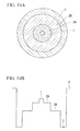
- FIG. 14A and FIG. 14B show a fiber that has a conventional triple-clad structure.
- FIG. 14A is a cross-sectional view of a fiber with a triple-clad structure
- FIG. 14B is a drawing that shows the refractive index profile of the cross section of the fiber.
- the fiber has a structure in which a first cladding 2A, a second cladding 2B, and a third cladding (outer cladding 3) are provided in that order in a concentric circular manner on the outside of a core 1 that has been doped with a rare-earth element, with a protective coating 4 provided further to the outside thereof.
- a rare-earth doped core multi-clad fiber that has a multi-clad structure (hereinbelow referred to as a rare-earth doped core multi-clad fiber) as an amplifying medium
- a skew mode of pumping light that propagates through the inner cladding as one restriction factor of the amplification (or laser oscillation) efficiency.
- Patent Document 2 describes the skew mode in detail. Due to the skew mode, pumping light, which should be used for amplification of the signal light by being absorbed in rare-earth ions that have been doped into the core, propagates through the fiber such that the pumping light propagates through the inner cladding in a waveguide mode without across the core.
- a method of reducing the influence of the skew mode by shifting the center axes of the core and cladding eccentric core structure, refer to Patent Document 1
- a method of reducing the skew mode itself by making a portion of the periphery of the inner cladding D-shape structure, refer to Patent Document 3
- polygonal structure refer to Patent Document 2 and Non-Patent Document 1 non-circular
- a polygonal cladding structure is a structure that is best used from the viewpoint of manufacturing, and is an effective method.
- the present invention was devised in view of the above circumstances, and has as an object the provision of a rare-earth doped core multi-clad fiber for an optical amplifier and fiber laser that has low skew and is inexpensive.
- an aspect of the present invention provides a rare-earth doped core multi-clad fiber which includes: a core that includes a rare-earth element; and a plurality of cladding layers that surround the core, in which: an outermost cladding of the plurality of cladding layers is made of polymer cladding; the plurality of cladding layers have a polygonal inner cladding; and a shape of a boundary between a second cladding from the outside and the outermost cladding does not have two-fold rotational symmetry.
- the difference between the maximum outer diameter and the minimum outer diameter of the cross section of the polygonal inner cladding be 6% or less of the average outer diameter; and that the cross section of the polygonal inner cladding have 15 sides or less.
- the cross section of the polygonal inner cladding be substantially a regular polygonal shape which has five sides or more and does not have two-fold rotational symmetry.
- the regular polygon be a pentagon, a heptagon, or a nonagon.
- the fiber include at least one of Yb or Er as the rare-earth element.
- the multi-clad fiber be a double-clad fiber.
- the present invention provides a fiber amplifier that has the afore-mentioned rare-earth doped core multi-clad fiber as a light amplifying medium.
- the present invention provides a fiber laser that has the afore-mentioned rare-earth doped core multi-clad fiber as a light amplifying medium.
- the shape of the boundary between the second cladding from the outside and the outermost cladding does not have two-fold rotational symmetry, during fabrication of a fiber perform for fiber drawing, it is possible to improve controllability of the outer diameter of the second cladding from the outside. As a result, it is possible to provide a rare-earth doped core multi-clad fiber that has an outstanding skew mode constraining effect and is manufactured at low cost.
- the fiber amplifier and fiber laser of the present invention includes the rare-earth doped core multi-clad fiber of the present invention which has an outstanding skew mode constraining effect and is manufactured at low cost, as a light amplifying medium. As a result, it is possible to provide a low cost fiber amplifier and fiber laser.
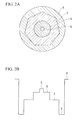
- FIG. 2A and FIG. 2B show a first embodiment of a rare-earth doped core multi-clad fiber according to the present invention, with FIG. 2A being a cross-sectional view of the rare-earth doped core multi-clad fiber, and FIG. 2B being a drawing that shows the refractive index profile of the cross section of the fiber.
- the rare-earth doped core multi-clad fiber of the present embodiment has a structure in which a first cladding 6 is concentrically provided on the outside of a core 5 that is doped with a rare-earth element, a second cladding 7 having a regular heptagonal cross section is provided on the outside of the first cladding 6, a third cladding 8 which is the outermost cladding made of a polymer and has a circular cross section is provided on the outside of the second cladding 7, and a protective coating 9 is provided on the outside thereof.
- a rare-earth element is also doped in the core 5.
- the doping region of the rare-earth element may be the entire core 5, or may be a portion of the core 5.
- the rare-earth element may be doped to a portion of the first cladding 6.
- a waveguide structure is formed by raising the refractive index of the core 5 higher than that of the surrounding cladding 6. In this waveguide structure, seed light to be amplified, the amplified signal light, the oscillated laser light, and the like, are guided.
- Dopants that raise the refractive index include Ge, Al, P and the like. They may be used together, or may be used with F, B and the like.
- a rare-earth element doped in the core 5 is selected according to the pumping wavelength, amplification wavelength, and laser oscillation wavelength.
- Er is used in order to obtain output at the wavelength of 1550 nm, which is used in optical tele-communication
- Yb is used in order to obtain output at the wavelength of 1060 nm, which is used in material processing.
- Tm, Bi, Cr, Ce, Nd, Eu, or the like may be added.
- not only doping of a single rare-earth element but co-doping of two or more rare-earth elements is performed in some cases.
- the refractive index profile of the core 5 is a step like profile in which the refractive index of the core is constant, but according to the requirements for the optical characteristics of the core 5 determined by the refractive index of the core 5, various refractive index profiles such as a dual-shape type, a segment core type, and a ring type may be adopted.
- the core 5 is generally used for single mode propagation, multi-mode propagation is also possible, and it may also have a structure of effectively single mode propagation so as to remove higher-order modes by bending (although the waveguide structure is multi-mode).
- the cladding configuration is as simple as possible, it is preferable for multi-cladding to have double cladding or triple cladding.
- double cladding is preferable, but when there are characteristic requirements, triple cladding and beyond (quadruple cladding) may be used.
- the optimal structure may be suitably selected in consideration of these required characteristics and cost.
- the present embodiment illustrates a fiber in which the core 5, the first cladding 6 and the second cladding 7 are made of a silica glass-based material, but the present invention is not limited thereto.
- Pumping light for exciting the rare-earth element so as to amplify signal light is guided in the first cladding 6 and the second cladding 7 (the inner cladding in the case of a double-clad fiber).
- the first cladding 6 and the second cladding 7 also have waveguide structures since the third cladding 8 with a lower refractive index is disposed on the outside thereof.
- a dopant that raises the refractive index may be added to the second cladding 7, or a holey cladding in which holes are provided in glass that constitutes a fiber so as to substantially reduce the refractive index may be provided between the second cladding 7 and the third cladding 8.
- a polymer with a lower refractive index than the second cladding 7 is provided on the outside of the second cladding 7. Since this polymer cladding is an outer cladding material that is outstanding in terms of productivity and is manufactured at low cost, it is possible to provide an inexpensive fiber.
- the shape of the boundary between the second cladding 7 that is the second cladding from the outside and the third cladding 8 that is the outermost cladding is a regular heptagonal shape that does not have two-fold rotational symmetry.
- the improvement in controllability of the outer diameter when the boundary shape between the second cladding from the outside and the outermost cladding does not have two-fold rotational symmetry will be described using a regular polygon as an example.
- the polygon with the minimum number of sides in which the boundary shape between the second cladding from the outside and the outermost cladding has two-fold rotational symmetry is a square, while the polygon with the minimum number of sides in which the boundary shape does not have two-fold rotational symmetry is a triangle.
- FIG. 5 is a cross-sectional view that shows a triangular double-clad fiber 18 in which an inner cladding 16 having a triangular cross section is provided on the outside of a core 15, and an outer cladding 17 is provided on the outside of the inner cladding 16.
- FIG. 6 is a cross-sectional view that shows a square double-clad fiber 22 in which an inner cladding 20 having a square cross section is provided on the outside of a core 19, and an outer cladding 21 is provided on the outside of the inner cladding 20.
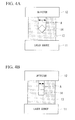
- FIG. 3 and FIGS. 4A and 4B are configuration diagrams that illustrate the method of measuring the outer diameter of the optical fibers 10 and 14, with FIG. 3 being the case of the optical fiber 10 having a circular cross section, FIG. 4A the case of measuring the maximum outer diameter of the optical fiber 14 having a square cross section, and FIG. 4B the case of measuring the minimum outer diameter of the optical fiber 14 having a square cross section.
- reference numeral 10 denotes an optical fiber with a circular cross section
- 11 denotes a laser source
- 12 denotes a detector
- 13 denotes a laser light
- 14 denotes an optical fiber with a square cross section.
- the optical fibers 10 and 14 are inserted between the laser source 11 that emits the laser light 13 in a strip shape or plane shape and the detector 12 that receives this laser light 13.
- the outer diameter A of the optical fiber 10 or 14 is measured.
- FIG. 4A and FIG. 4B in the case of measuring the outer diameter of a fiber whose cross section is polygonal, an angular dependency arises in which the outer diameter of the cross section differs depending on the angle it is viewed from.
- FIG. 7 shows the angular dependency in the case of measuring the outer diameter of an optical fiber with a triangular cross section
- FIG. 8 shows the angular dependency in the case of measuring the outer diameter of an optical fiber with a square cross section.
- the radius of a circle that circumscribes a polygon of the cross section is normalized to be 1.
- the fewer the number of sides the greater the constrainment of the skew mode.
- the outer diameter is more stable when the difference between the maximum diameter and minimum diameter of the angular dependency of an outer diameter (to be precise, the ratio of the difference with respect to the average outer diameter) is smaller.
- the ratio of the difference between the maximum diameter and the minimum diameter with respect to the average diameter is 27% and 37%, respectively. Therefore, the outer diameter controllability is better for a triangular cross section. Accordingly, the skew mode constrainment and outer diameter stability are better in the case of the cross section being triangular. This is the advantage of the boundary shape between the second cladding and the outermost cladding not having two-fold rotational symmetry.
- a fiber preform is a cylindrical glass body in which, while having the same cross-sectional refractive index profile as a fiber or a portion of a fiber, the outer diameter is between several times to several thousand times greater than that of the fiber.
- a step of coating the outside of the fiber with a resin or polymer and curing it is performed, thereby providing a protective resin layer or polymer cladding.
- a resin or polymer that has a heat-curable property or UV-curable property is used, and so by placing a heat source or UV light source downward through which it passes after coating, it is possible to deploy a protective resin layer or polymer cladding in an online manner in the fiber drawing process. Also, by disposing them in series, it is possible to provide a polymer cladding layer and protective resin layer in one time.
- Fiber outer diameter referred here may mean the outer diameter including the polymer or resin, or only the glass portion (the region to the inner cladding) prior to coating with the polymer or the like. This choice depends on which should be more precisely controlled.
- Non-Patent Document 2 and the like disclose a number of examples of outer diameter measurement methods. Also, Patent Document 4 and Patent Document 5 disclose fiber drawing processes and outer diameter measurement and control methods.
- the shape of the outer circumference of the glass of the fiber (in the case of the present invention, the shape of the boundary between the second cladding from the outside and the outermost cladding) is generally circular.
- the outer diameter thereof is constant at any angle it is viewed from.
- the outer diameter measuring apparatus is normally fixed at a predetermined position, and the outer diameter is measured from one direction (refer to Patent Document 5).
- the outer diameter measurement direction may be two directions shifted by 90 degrees, but since the device cost increases by the number of outer diameter measuring apparatuses, it is not advantageous for manufacturing an inexpensive fiber.
- the fiber when drawing a fiber, the fiber does not constantly maintain the same angle at the position of measuring the outer diameter due to twisting or the like during spooling or drawing of the fiber, and so fluctuations in angle occur during fiber drawing. Accordingly, the relative angle of the outer diameter measuring apparatus with respect to the fiber axis is not constant over time. That is, in the case of drawing a fiber in which the cross section is not circular, in accordance with the fluctuation in angle during fiber drawing, the measured value of the fiber outer diameter is erroneously detected as the fiber outer diameter fluctuating in the lengthwise direction by the rotation (that is, in spite of performing uniform diameter drawing in actuality, a diameter fluctuation due to the angle will be detected).
- the shape of the boundary between the second cladding from the outside and the outermost cladding is constituted to not have two-fold rotational symmetry, it is possible to lessen the difference between the maximum diameter and the minimum diameter of the angular dependency of the outer diameter of the inner cladding (to be precise, the ratio of the difference with respect to the average outer diameter of the inner cladding).
- it is possible to readily control the outer diameter of the fiber and it is possible to manufacture a fiber with a good yield. Therefore, it is possible to manufacture a rare-earth doped core multi-clad fiber at a reasonable price.
- the ratio of the difference between the maximum diameter and the minimum diameter with respect to the average diameter is smaller.
- the ratio of the difference is 7% or less, it is possible to improve the yield of the fiber outer diameter, and is preferably 3% or less.
- constrainment of the skew mode is insufficient due to the closer periphery shape to a circle.
- the number of sides of a polygon should be limited to 15 or less.
- a five-sided polygon or greater is preferred.
- a polygon of 17 or more sides is not preferred from the viewpoint of man-hour and skew mode suppression.
- a pentagon, heptagon, and nonagon are preferred from the viewpoint of skew mode suppression and lower costs (fiber drawing stability, polygon processing). According to the investigations of the inventors, among these, the heptagon is the most balanced.
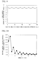
- FIG. 9 is a graph that shows the angular dependency of the outer diameter in the case of the heptagonal cross section.
- FIG. 10 shows the numerical computation result that indicates the relationship between each polygon and the ratio of the difference between the maximum diameter and the minimum diameter with respect to the average diameter.
- a heptagonal double-clad fiber in which the cross sectional shape of the inner cladding is a regular heptagon as shown in FIG. 11 was fabricated.
- reference numeral 23 denotes a core
- 24 an inner cladding
- 25 an outer cladding made of polymer
- 26 a heptagonal double-clad fiber.
- the manufacturing method of a fiber preform was a combination of the VAD method and the solution method, and the fiber was drawn while controlling the outer diameter after trimming the outer periphery of the inner cladding into a regular heptagon.
- the circumscribing circle of the heptagon was approximately 400 ⁇ m
- the core diameter was approximately 20 ⁇ m
- the relative refractive-index difference ( ⁇ ) of the core was approximately 0.13%.
- Doping was performed to approximately 1 wt% using ytterbium (Yb) as the rare-earth element.
- Yb ytterbium
- a UV-curable polymer cladding agent was coated on the drawn fiber with a thickness of approximately 20 ⁇ m and then was cured to form the outer cladding.
- Example 1 As a comparative example, a double-clad fiber with an inner cladding having a circular cross section as shown in FIG. 1 was fabricated, with the same materials and dimensions as Example 1.
- FIG. 12 shows a comparison of the length-dependency of the Yb absorption between the heptagonal double-clad fiber and the circular double-clad fiber (comparative example).
- FIG. 12 shows that, in the case of the absorption being proportional to the length, this means that there is no skew mode. Conversely, a fiber in which absorption becomes less as the length becomes longer is a fiber in which skew modes are large and so the amplification efficiency becomes low. From FIG. 12 , it is evident that the absorption is more proportional to the length for the fiber processed into a heptagon (Example 1), and so the skew modes are few.
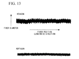
- FIG. 13 shows the result of measuring online the outer diameter of the optical fiber during fiber drawing. Compared to the hexagon (comparative example), the heptagon had better outer diameter stability. Also, with regard to the outer diameter of the fiber that was obtained as a result, in the case of the heptagon, variability in the outer diameter is less, and so a fiber with stable characteristics was obtained.
- the triple-clad fiber in which the cross section of the second cladding from the outside is a regular heptagon as shown in FIG. 2 was fabricated.
- the fabrication method of a fiber perform was a combination of the MCVD method and the solution method, and fiber was drawn while controlling the outer diameter after grinding the outer periphery of the second cladding into a heptagon.
- the circumscribing circle of the heptagon was approximately 400 ⁇ m
- the core diameter was approximately 30 ⁇ m
- the relative refractive-index difference ( ⁇ ) of the core was approximately 0.13%.
- Doping was performed to approximately 2 wt% using ytterbium (Yb) as the rare-earth element.
- a UV-curable polymer cladding agent was coated on the drawn fiber with a thickness of approximately 20 ⁇ m and then was cured to form the outer cladding.
- Table 1 shows a list of trial production fibers of Example 3 to Example 11.
- Example 3 Example 4
- Example 5 Example 6
- Example 7 Example 8
- Example 10 Example 11 No. of cladding layers - 2 3 2 2 2 2 2 2 4 No. of glass cladding layers - 1 2 1 1 1 1 1 1 3 No. of polymer cladding layers - 1 1 1 1 1 1 1 1 No.
- Table 1 shows the broad application range of the present invention, and does not particularly show the result of comparison with comparative examples.
- the rare-earth doped core multi-clad fibers of Example 3 to Example 11 the same effects as the above-described examples were obtained.
Landscapes
- Physics & Mathematics (AREA)
- General Physics & Mathematics (AREA)
- Optics & Photonics (AREA)
- Lasers (AREA)
Abstract
A rare-earth doped core multi-clad fiber that includes: a core that includes a rare-earth element; and a plurality of cladding layers that surround the core, in which: an outermost cladding of the plurality of cladding layers is made of polymer cladding; the plurality of cladding layers have a polygonal inner cladding; and a shape of a boundary between a second cladding from the outside and the outermost cladding does not have two-fold rotational symmetry. As a result, it is possible to provide a rare-earth doped core multi-clad fiber for an optical amplifier and fiber laser that has low skew and is inexpensive.
Description
- The present invention relates to a fiber amplifier or a fiber laser in light amplification and light oscillation technology that inputs pumping light into a multi-clad fiber and outputs after amplifying or laser oscillating signal light by stimulated emission by the pumping light, and particularly relates to a rare-earth doped core multi-clad fiber with a structure in which the pumping light is efficiently coupled to a core in a multi-clad fiber while constraining skew light and a structure in which an outer diameter of the fiber is easily controlled during fiber drawing and the outer diameter of the fiber is stable, and to a high performance and low-cost fiber amplifier and fiber laser that use this fiber. Priority is claimed on Japanese Patent Application No.
2007-220891, filed August 28, 2007 - In a fiber amplifier or a fiber laser that amplifies or laser oscillates signal light by an optical fiber that is doped with a rare-earth element, a need for higher output power of the fiber amplifier or the fiber laser has been increased. As one method of achieving high output power, a method in which a waveguide structure of a rare-earth doped optical fiber serving as an amplifying medium is made into a multi-clad structure such as a so-called double-clad structure or triple-clad structure, in which a plurality of waveguide structures are provided in a concentric circular manner, has been proposed. This method has contributed to higher output power of fiber amplifiers and fiber lasers.
-
FIG. 1 is a drawing that shows one example of a refractive index profile of the cross section of a fiber that has a double-clad structure of conventional rare-earth doped optical fibers. The double-clad fiber of this example has acore 1 that is doped with a rare-earth element, aninner cladding 2 that surrounds the periphery of thecore 1, and anouter cladding 3 that surrounds theinner cladding 2. The refractive index is highest for thecore 1, with a rare-earth element being doped therein. On the periphery thereof is disposed theinner cladding 2 with a refractive index lower than that of thecore 1. Further to the outside thereof is disposed theouter cladding 3 with a refractive index that is lower than that of theinner cladding 2. Generally, aprotective coating 4 that is made of a resin such as UV-curable resin for protecting the fiber is coated on the outside thereof. - In the some cases of adopting a multi-clad structure, the inner cladding has a plurality of layer structures (refer to Patent Document 6). As one example,
FIG. 14A and FIG. 14B show a fiber that has a conventional triple-clad structure.FIG. 14A is a cross-sectional view of a fiber with a triple-clad structure, whileFIG. 14B is a drawing that shows the refractive index profile of the cross section of the fiber. The fiber has a structure in which afirst cladding 2A, asecond cladding 2B, and a third cladding (outer cladding 3) are provided in that order in a concentric circular manner on the outside of acore 1 that has been doped with a rare-earth element, with aprotective coating 4 provided further to the outside thereof. - In an amplifier or laser oscillator that uses a rare-earth doped fiber that has a multi-clad structure (hereinbelow referred to as a rare-earth doped core multi-clad fiber) as an amplifying medium, there is a skew mode of pumping light that propagates through the inner cladding as one restriction factor of the amplification (or laser oscillation) efficiency. For example,
Patent Document 2 describes the skew mode in detail. Due to the skew mode, pumping light, which should be used for amplification of the signal light by being absorbed in rare-earth ions that have been doped into the core, propagates through the fiber such that the pumping light propagates through the inner cladding in a waveguide mode without across the core. For this reason, there are problems of having to make the fiber length longer in order to obtain the required gain, to decrease in the amplification efficiency, and the like. Moreover, since perturbations (bending, twisting, and the like) greatly influence the skew mode, when the probability of the skew mode is large, a problem of the output not being stable arises. - Various methods in relation to countermeasures against the skew modes have been proposed. For example, a method of reducing the influence of the skew mode by shifting the center axes of the core and cladding (eccentric core structure, refer to Patent Document 1) and a method of reducing the skew mode itself by making a portion of the periphery of the inner cladding (D-shape structure, refer to Patent Document 3) or the entire of the periphery of the inner cladding (polygonal structure, refer to
Patent Document 2 and Non-Patent Document 1) non-circular have been proposed. Among these methods, a polygonal cladding structure is a structure that is best used from the viewpoint of manufacturing, and is an effective method. - [Patent Document 1] Japanese Unexamined Patent Application, First Publication No.
H01-260405 - [Patent Document 2] Published Japanese Translation No.
H10-503885 of the PCT - [Patent Document 3] Published Japanese Translation No.
H10-510104 of the PCT - [Patent Document 4] Japanese Unexamined Patent Application, First Publication No.
H06-206734 - [Patent Document 5] Japanese Unexamined Patent Application, First Publication No.
H08-319129 - [Patent Document 6]
PCT International Publication No. WO2006-017802 pamphlet - [Non-Patent Document 1] M.H. Muendel, CLEO, '96 CTuU2
- [Non-Patent Document 2] http://www.keyence.co.jp/hennilsokuteiki/index.jsp
- However, in the conventional techniques described above, there are mainly difficulties in the manufacturing of a rare-earth doped core multi-clad fiber, and it has not been possible to manufacture a fiber of the required structure at a reasonable cost.
First, in the eccentric core fiber disclosed inPatent Document 1, there are difficulties in the manufacture of a fiber preform. This is because the general manufacturing conditions (including the VAD method or MCVD method, OVD method, PCVD method and the like) of fiber preforms in which the preform is manufactured coaxially, and the requirement of eccentricity are opposed to each other, so in order to realize both requirements, it is necessary to perform eccentric grinding of the preform.
Also, there are manufacturing difficulties in the D-shape structure that is disclosed inPatent Document 3 and the polygonal structure disclosed inPatent Document 2 and Non-PatentDocument 1, so it is not realized that a fiber with the desired structure is manufactured cheaply. - The present invention was devised in view of the above circumstances, and has as an object the provision of a rare-earth doped core multi-clad fiber for an optical amplifier and fiber laser that has low skew and is inexpensive.
- In order to achieve the object, an aspect of the present invention provides a rare-earth doped core multi-clad fiber which includes: a core that includes a rare-earth element; and a plurality of cladding layers that surround the core, in which: an outermost cladding of the plurality of cladding layers is made of polymer cladding; the plurality of cladding layers have a polygonal inner cladding; and a shape of a boundary between a second cladding from the outside and the outermost cladding does not have two-fold rotational symmetry.
- In the rare-earth doped core multi-clad fiber of the present invention, it is preferable that the difference between the maximum outer diameter and the minimum outer diameter of the cross section of the polygonal inner cladding be 6% or less of the average outer diameter; and that the cross section of the polygonal inner cladding have 15 sides or less.
- In the rare-earth doped core multi-clad fiber of the present invention, it is preferable that the cross section of the polygonal inner cladding be substantially a regular polygonal shape which has five sides or more and does not have two-fold rotational symmetry.
- In the rare-earth doped core multi-clad fiber of the present invention, it is preferable that the regular polygon be a pentagon, a heptagon, or a nonagon.
- In the rare-earth doped core multi-clad fiber of the present invention, it is preferable that the fiber include at least one of Yb or Er as the rare-earth element.
- In the rare-earth doped core multi-clad fiber of the present invention, it is preferable that the multi-clad fiber be a double-clad fiber.
- Also, the present invention provides a fiber amplifier that has the afore-mentioned rare-earth doped core multi-clad fiber as a light amplifying medium.
- Also, the present invention provides a fiber laser that has the afore-mentioned rare-earth doped core multi-clad fiber as a light amplifying medium.
- In the rare-earth doped core multi-clad fiber of the present invention, since the shape of the boundary between the second cladding from the outside and the outermost cladding does not have two-fold rotational symmetry, during fabrication of a fiber perform for fiber drawing, it is possible to improve controllability of the outer diameter of the second cladding from the outside. As a result, it is possible to provide a rare-earth doped core multi-clad fiber that has an outstanding skew mode constraining effect and is manufactured at low cost.
- Also, the fiber amplifier and fiber laser of the present invention includes the rare-earth doped core multi-clad fiber of the present invention which has an outstanding skew mode constraining effect and is manufactured at low cost, as a light amplifying medium. As a result, it is possible to provide a low cost fiber amplifier and fiber laser.
-
-
FIG. 1 is a drawing that shows one example of a refractive index profile of a cross section of an optical fiber that has a conventional double-clad structure. -
FIG. 2A is a cross-sectional view that shows one embodiment of a rare-earth doped core multi-clad optical fiber of the present invention. -
FIG. 2B is a drawing that shows the refractive index profile of the optical fiber shown inFIG. 2A . -
FIG. 3 is an outline diagram that shows a typical method of measuring an outer diameter of an optical fiber during drawing process. -
FIG. 4A is an outline diagram that shows an example of a method of measuring an outer diameter of an optical fiber having a square cross section during drawing process. -
FIG. 4B is an outline diagram that shows an example of a method of measuring an outer diameter of an optical fiber having a square cross section during drawing process. -
FIG. 5 is a cross-sectional view of a triangular double-clad fiber. -
FIG. 6 is a cross-sectional view of a square double-clad fiber. -
FIG. 7 is a graph that shows the angular dependency of an outer diameter of a triangular double-clad fiber. -
FIG. 8 is a graph that shows the angular dependency of an outer diameter of a square double-clad fiber. -
FIG. 9 is a graph that shows the angular dependency of an outer diameter of a heptagonal double-clad fiber. -
FIG. 10 is a graph that shows the relationship between the number of sides of the cross section of a polygonal optical fiber and the fluctuation of the outer diameter due to the angle change. -
FIG. 11 is a cross-sectional view of a heptagonal double-clad fiber fabricated in Example 1. -
FIG. 12 is a graph that shows the result of Example 1 and shows a comparison of the dependency of absorption on the fiber length between the heptagonal double-clad fiber and a circular double-clad fiber (comparative example). -
FIG. 13 is a graph that shows the result of Example 1 and shows a comparison of outer diameter stability between the heptagonal double-clad fiber and a hexagonal double-clad fiber (comparative example). -
FIG. 14A is a cross-sectional view of a triple-clad fiber. -
FIG. 14B is a drawing that shows the refractive index profile of the cross section of the optical fiber shown inFIG. 14A . -
- 1, 5, 15, 19, 23
- CORE
- 2, 2A, 2B, 16, 20, 24
- INNER CLADDING
- 3, 7,21
- OUTER CLADDING
- 4, 9
- PROTECTIVE COATING
- 6
- FIRST CLADDING
- 7
- SECOND CLADDING
- 8
- THIRD CLADDING
- 10, 4
- OPTICAL FIBER
- 11
- LASER SOURCE
- 12
- DETECTOR
- 13
- LASER LIGHT
- 18
- TRIANGULAR DOUBLE-CLAD FIBER
- 22
- SQUARE DOUBLE-CLAD FIBER
- 26
- HEPTAGONAL DOUBLE-CLAD FIBER
- Hereinbelow an embodiment of the present invention will be described with reference to the appended drawings.
FIG. 2A and FIG. 2B show a first embodiment of a rare-earth doped core multi-clad fiber according to the present invention, withFIG. 2A being a cross-sectional view of the rare-earth doped core multi-clad fiber, andFIG. 2B being a drawing that shows the refractive index profile of the cross section of the fiber. The rare-earth doped core multi-clad fiber of the present embodiment has a structure in which afirst cladding 6 is concentrically provided on the outside of acore 5 that is doped with a rare-earth element, asecond cladding 7 having a regular heptagonal cross section is provided on the outside of thefirst cladding 6, athird cladding 8 which is the outermost cladding made of a polymer and has a circular cross section is provided on the outside of thesecond cladding 7, and aprotective coating 9 is provided on the outside thereof. - Besides a dopant that raises the refractive index, a rare-earth element is also doped in the
core 5. The doping region of the rare-earth element may be theentire core 5, or may be a portion of thecore 5. Moreover, the rare-earth element may be doped to a portion of thefirst cladding 6. A waveguide structure is formed by raising the refractive index of thecore 5 higher than that of the surroundingcladding 6. In this waveguide structure, seed light to be amplified, the amplified signal light, the oscillated laser light, and the like, are guided. Dopants that raise the refractive index include Ge, Al, P and the like. They may be used together, or may be used with F, B and the like. - A rare-earth element doped in the
core 5 is selected according to the pumping wavelength, amplification wavelength, and laser oscillation wavelength. Er is used in order to obtain output at the wavelength of 1550 nm, which is used in optical tele-communication, and Yb is used in order to obtain output at the wavelength of 1060 nm, which is used in material processing. In addition, Tm, Bi, Cr, Ce, Nd, Eu, or the like may be added. Also, in order to avoid upconversion or to obtain a sensitization action by co-doping, not only doping of a single rare-earth element but co-doping of two or more rare-earth elements is performed in some cases. Similarly, Ge, Al, P, F, B and the like and combinations thereof are generally used as a refractive-index adjustment dopant. In addition, Ti, Bi, Cl and the like are also conceivable as a dopant. Also, dispersing agent of a rare-earth element may also be added simultaneously. Suitable dispersing agents other than the above include Cr, Ga, In, As, Sb, and the like.
Generally, the refractive index profile of thecore 5 is a step like profile in which the refractive index of the core is constant, but according to the requirements for the optical characteristics of thecore 5 determined by the refractive index of thecore 5, various refractive index profiles such as a dual-shape type, a segment core type, and a ring type may be adopted. Moreover, although thecore 5 is generally used for single mode propagation, multi-mode propagation is also possible, and it may also have a structure of effectively single mode propagation so as to remove higher-order modes by bending (although the waveguide structure is multi-mode). - In the rare-earth doped core multi-clad fiber according to the present invention, since it is advantageous in terms of cost that the cladding configuration is as simple as possible, it is preferable for multi-cladding to have double cladding or triple cladding. When there are no particular characteristic requirements, simpler double cladding is preferable, but when there are characteristic requirements, triple cladding and beyond (quadruple cladding) may be used. The optimal structure may be suitably selected in consideration of these required characteristics and cost. The present embodiment illustrates a fiber in which the
core 5, thefirst cladding 6 and thesecond cladding 7 are made of a silica glass-based material, but the present invention is not limited thereto. - Pumping light for exciting the rare-earth element so as to amplify signal light is guided in the
first cladding 6 and the second cladding 7 (the inner cladding in the case of a double-clad fiber). Thefirst cladding 6 and thesecond cladding 7 also have waveguide structures since thethird cladding 8 with a lower refractive index is disposed on the outside thereof. By inputting pumping light into thefirst cladding 6 and thesecond cladding 7 and not thecore 5, it is possible to broaden the light-guiding cross-sectional area of the pumping light, and as a result, the power density of pumping light falls, and it becomes possible to avoid optical damage of the fiber due to the pumping light. Therefore, it is possible to input a larger amount of pumping light into the rare-earth doped core multi-clad fiber, and it becomes possible to obtain output light of greater power without destroying a fiber. - There are a number of methods of imparting a difference in the refractive index between the
second cladding 7 and the third cladding 8 (in the case of a double-clad fiber, the inner cladding and outer cladding). A dopant that raises the refractive index may be added to thesecond cladding 7, or a holey cladding in which holes are provided in glass that constitutes a fiber so as to substantially reduce the refractive index may be provided between thesecond cladding 7 and thethird cladding 8. Most generally a polymer with a lower refractive index than thesecond cladding 7 is provided on the outside of thesecond cladding 7. Since this polymer cladding is an outer cladding material that is outstanding in terms of productivity and is manufactured at low cost, it is possible to provide an inexpensive fiber. - In the rare-earth doped core multi-clad fiber of the present embodiment, the shape of the boundary between the
second cladding 7 that is the second cladding from the outside and thethird cladding 8 that is the outermost cladding is a regular heptagonal shape that does not have two-fold rotational symmetry. Thereby, it is possible to inhibit the skew mode of the fiber, improve the controllability of the outer shape of thesecond cladding 7, and achieve low-cost production. - The improvement in controllability of the outer diameter when the boundary shape between the second cladding from the outside and the outermost cladding does not have two-fold rotational symmetry will be described using a regular polygon as an example.
The polygon with the minimum number of sides in which the boundary shape between the second cladding from the outside and the outermost cladding has two-fold rotational symmetry is a square, while the polygon with the minimum number of sides in which the boundary shape does not have two-fold rotational symmetry is a triangle.FIG. 5 is a cross-sectional view that shows a triangular double-clad fiber 18 in which an inner cladding 16 having a triangular cross section is provided on the outside of a core 15, and anouter cladding 17 is provided on the outside of the inner cladding 16. Also,FIG. 6 is a cross-sectional view that shows a square double-cladfiber 22 in which aninner cladding 20 having a square cross section is provided on the outside of a core 19, and anouter cladding 21 is provided on the outside of theinner cladding 20. -
FIG. 3 andFIGS. 4A and 4B are configuration diagrams that illustrate the method of measuring the outer diameter of theoptical fibers FIG. 3 being the case of theoptical fiber 10 having a circular cross section,FIG. 4A the case of measuring the maximum outer diameter of theoptical fiber 14 having a square cross section, andFIG. 4B the case of measuring the minimum outer diameter of theoptical fiber 14 having a square cross section. In these drawings,reference numeral 10 denotes an optical fiber with a circular cross section, 11 denotes a laser source, 12 denotes a detector, 13 denotes a laser light, and 14 denotes an optical fiber with a square cross section. In this outer diameter measuring method, theoptical fibers laser source 11 that emits thelaser light 13 in a strip shape or plane shape and thedetector 12 that receives thislaser light 13. By finding a portion where the laser light is blocked corresponding to the outer diameter of theoptical fiber optical fiber FIG. 4A and FIG. 4B , in the case of measuring the outer diameter of a fiber whose cross section is polygonal, an angular dependency arises in which the outer diameter of the cross section differs depending on the angle it is viewed from. - Using the outer diameter measuring method shown in
FIGS. 3 to 4B ,FIG. 7 shows the angular dependency in the case of measuring the outer diameter of an optical fiber with a triangular cross section, andFIG. 8 shows the angular dependency in the case of measuring the outer diameter of an optical fiber with a square cross section. In this case, the radius of a circle that circumscribes a polygon of the cross section is normalized to be 1. For a regular polygon, the fewer the number of sides, the greater the constrainment of the skew mode. In conceptual terms, it could be regarded such that the greater the deformation in shape from a circle, the more the skew mode is constrained (precisely, it is possible to calculate by using ray tracing method or the like). Accordingly, it is possible to constrain the skew mode more effectively with a triangular cross section than with a square cross section. On the other hand, from the viewpoint of outer diameter controllability, the outer diameter is more stable when the difference between the maximum diameter and minimum diameter of the angular dependency of an outer diameter (to be precise, the ratio of the difference with respect to the average outer diameter) is smaller. In the case of triangle and square, the ratio of the difference between the maximum diameter and the minimum diameter with respect to the average diameter is 27% and 37%, respectively. Therefore, the outer diameter controllability is better for a triangular cross section. Accordingly, the skew mode constrainment and outer diameter stability are better in the case of the cross section being triangular. This is the advantage of the boundary shape between the second cladding and the outermost cladding not having two-fold rotational symmetry. - Next, a description of the fiber drawing step of transforming a fiber preform into a fiber of the desired structure, and a description of the low manufacturability of conventional fibers that was disclosed in
Patent Documents 1 to 3 mentioned above will be given. Note that in actual fiber manufacturing, in most cases the angle of a polygon takes on some rounding because the manufacturing process includes a step of applying heat. Also, in relation to a regular polygon, small deformation from a regular polygon may occur from the viewpoint of processing accuracy, but such misalignment from these theoretical shapes does not affect the skew mode controllability and outer diameter stability. Accordingly, it need only be a substantial polygon or a substantial regular polygon, and moreover the substantial polygon or the substantial regular polygon also includes that with manufacturing deformations. - A fiber preform is a cylindrical glass body in which, while having the same cross-sectional refractive index profile as a fiber or a portion of a fiber, the outer diameter is between several times to several thousand times greater than that of the fiber. In manufacturing process, by lowering the viscosity of the fiber preform in a heat furnace and pulling the lower end of the preform from the bottom of the furnace, a fiber is thinly elongated and made to a glass fiber with desired outer diameter. This process is called fiber drawing. By controlling the furnace temperature, tension, speed of pulling, outer diameter and the like by various methods, the desired optical glass fiber can be obtained. Generally, immediately after this drawing step, a step of coating the outside of the fiber with a resin or polymer and curing it is performed, thereby providing a protective resin layer or polymer cladding. A resin or polymer that has a heat-curable property or UV-curable property is used, and so by placing a heat source or UV light source downward through which it passes after coating, it is possible to deploy a protective resin layer or polymer cladding in an online manner in the fiber drawing process. Also, by disposing them in series, it is possible to provide a polymer cladding layer and protective resin layer in one time.
- In such a fiber drawing step, the main factors influencing the manufacturability of a conventional D-shape cladding structure or polygonal cladding structure are difficulties relating to the outer diameter measurement and outer diameter control of a fiber. Normally, in outer diameter measurement/control of a fiber, while measuring the "outer diameter" obtained by a laser scanning or the like online, outer diameter control is performed so that the measured outer diameter becomes constant. Fiber outer diameter referred here may mean the outer diameter including the polymer or resin, or only the glass portion (the region to the inner cladding) prior to coating with the polymer or the like. This choice depends on which should be more precisely controlled. In the case of the present invention, since control of propagation of the pumping light in the inner cladding (that is, the glass cladding) is important, the diameter control of the glass portion is important. For that reason, it is preferable to measure and control the outer diameter of the glass portion.
Non-Patent Document 2 and the like disclose a number of examples of outer diameter measurement methods. Also,Patent Document 4 andPatent Document 5 disclose fiber drawing processes and outer diameter measurement and control methods. - Here, in an ordinary optical fiber drawing process, the shape of the outer circumference of the glass of the fiber (in the case of the present invention, the shape of the boundary between the second cladding from the outside and the outermost cladding) is generally circular. In the case of a fiber that has a circular cross section, the outer diameter thereof is constant at any angle it is viewed from.
- However, for example in the case of the D-shape cladding structure that is disclosed in
Patent Document 3, in the angle of a region including a side that is grinded into the D-shape, compared to an angle that does not include that side, the outer diameter is measured small. The outer diameter measuring apparatus is normally fixed at a predetermined position, and the outer diameter is measured from one direction (refer to Patent Document 5). The outer diameter measurement direction may be two directions shifted by 90 degrees, but since the device cost increases by the number of outer diameter measuring apparatuses, it is not advantageous for manufacturing an inexpensive fiber. - On the other hand, when drawing a fiber, the fiber does not constantly maintain the same angle at the position of measuring the outer diameter due to twisting or the like during spooling or drawing of the fiber, and so fluctuations in angle occur during fiber drawing. Accordingly, the relative angle of the outer diameter measuring apparatus with respect to the fiber axis is not constant over time. That is, in the case of drawing a fiber in which the cross section is not circular, in accordance with the fluctuation in angle during fiber drawing, the measured value of the fiber outer diameter is erroneously detected as the fiber outer diameter fluctuating in the lengthwise direction by the rotation (that is, in spite of performing uniform diameter drawing in actuality, a diameter fluctuation due to the angle will be detected). Since the outer diameter control tries to control the outer diameter based on such diameter fluctuation data, the actual fiber outer diameter ends up fluctuating, so it is difficult to draw the fiber diameter uniformly.
This causes the same result even in the case of a polygonal fiber. As a result, since microbending losses occur and the length of defective portions because of the fiber diameter irregularity becomes longer due to change of optical characteristics in the lengthwise direction, problems of fiber yields not improving and of the fiber cost rising arise. - In the present invention, since the shape of the boundary between the second cladding from the outside and the outermost cladding is constituted to not have two-fold rotational symmetry, it is possible to lessen the difference between the maximum diameter and the minimum diameter of the angular dependency of the outer diameter of the inner cladding (to be precise, the ratio of the difference with respect to the average outer diameter of the inner cladding). As a result, it is possible to readily control the outer diameter of the fiber, and it is possible to manufacture a fiber with a good yield. Therefore, it is possible to manufacture a rare-earth doped core multi-clad fiber at a reasonable price.
- Next, the requirements for minimizing the influence on outer diameter control will be described. Basically, it is desirable that the ratio of the difference between the maximum diameter and the minimum diameter with respect to the average diameter is smaller. According to the deliberations of the inventors, when the ratio of the difference is 7% or less, it is possible to improve the yield of the fiber outer diameter, and is preferably 3% or less. Conversely, even in the case of the fiber not having two-fold rotational symmetry, when a polygonal cross section is formed so as to lower the ratio of the difference to less than 1%, constrainment of the skew mode is insufficient due to the closer periphery shape to a circle. Also, in this case, as the number of sides increases, processing becomes more complicated and requires more man-hours, so is not desirable from a cost viewpoint. In that sense, the number of sides of a polygon should be limited to 15 or less.
- Also, when making the cross section into a regular polygon, it is preferred to give consideration to the ease of processing and the ease of connecting fibers to each other. Also, in order to make the ratio of the difference between the maximum diameter and the minimum diameter with respect to the
average diameter 7% or less, a five-sided polygon or greater is preferred. On the other hand, a polygon of 17 or more sides is not preferred from the viewpoint of man-hour and skew mode suppression. In particular, a pentagon, heptagon, and nonagon are preferred from the viewpoint of skew mode suppression and lower costs (fiber drawing stability, polygon processing). According to the investigations of the inventors, among these, the heptagon is the most balanced.FIG. 9 is a graph that shows the angular dependency of the outer diameter in the case of the heptagonal cross section. For reference,FIG. 10 shows the numerical computation result that indicates the relationship between each polygon and the ratio of the difference between the maximum diameter and the minimum diameter with respect to the average diameter. - In an optical amplifier or fiber laser manufactured using the rare-earth doped core multi-clad fiber of the present invention, since the skew mode of the fiber portion is constrained and the cost is lower, it becomes a high performance and low-cost device with a high amplification efficiency.
- A heptagonal double-clad fiber in which the cross sectional shape of the inner cladding is a regular heptagon as shown in
FIG. 11 was fabricated. InFIG. 11 ,reference numeral 23 denotes a core, 24 an inner cladding, 25 an outer cladding made of polymer, and 26 a heptagonal double-clad fiber. The manufacturing method of a fiber preform was a combination of the VAD method and the solution method, and the fiber was drawn while controlling the outer diameter after trimming the outer periphery of the inner cladding into a regular heptagon. In this fiber drawing, the circumscribing circle of the heptagon was approximately 400 µm, the core diameter was approximately 20 µm, and the relative refractive-index difference (Δ) of the core was approximately 0.13%.
Doping was performed to approximately 1 wt% using ytterbium (Yb) as the rare-earth element. Also, a UV-curable polymer cladding agent was coated on the drawn fiber with a thickness of approximately 20 µm and then was cured to form the outer cladding. - As a comparative example, a double-clad fiber with an inner cladding having a circular cross section as shown in
FIG. 1 was fabricated, with the same materials and dimensions as Example 1. -
FIG. 12 shows a comparison of the length-dependency of the Yb absorption between the heptagonal double-clad fiber and the circular double-clad fiber (comparative example).FIG. 12 shows that, in the case of the absorption being proportional to the length, this means that there is no skew mode. Conversely, a fiber in which absorption becomes less as the length becomes longer is a fiber in which skew modes are large and so the amplification efficiency becomes low. FromFIG. 12 , it is evident that the absorption is more proportional to the length for the fiber processed into a heptagon (Example 1), and so the skew modes are few. - Also, as another comparison, a double-clad fiber was fabricated in which the boundary between the inner cladding and the outer cladding is a regular hexagon, with the same materials and dimensions as the Example 1.
FIG. 13 shows the result of measuring online the outer diameter of the optical fiber during fiber drawing.
Compared to the hexagon (comparative example), the heptagon had better outer diameter stability. Also, with regard to the outer diameter of the fiber that was obtained as a result, in the case of the heptagon, variability in the outer diameter is less, and so a fiber with stable characteristics was obtained. - The triple-clad fiber in which the cross section of the second cladding from the outside is a regular heptagon as shown in
FIG. 2 was fabricated. The fabrication method of a fiber perform was a combination of the MCVD method and the solution method, and fiber was drawn while controlling the outer diameter after grinding the outer periphery of the second cladding into a heptagon. The circumscribing circle of the heptagon was approximately 400 µm, the core diameter was approximately 30 µm, and the relative refractive-index difference (Δ) of the core was approximately 0.13%. Doping was performed to approximately 2 wt% using ytterbium (Yb) as the rare-earth element. Also, a UV-curable polymer cladding agent was coated on the drawn fiber with a thickness of approximately 20 µm and then was cured to form the outer cladding. - As a result of trial production of a fiber laser using this fiber, it was possible to obtain a fiber laser with a high pumping light utilization efficiency of a slope efficiency of 55%.
- Table 1 shows a list of trial production fibers of Example 3 to Example 11.
-
[Table 1] Unit Example 3 Example 4 Example 5 Example 6 Example 7 Example 8 Example 9 Example 10 Example 11 No. of cladding layers - 2 3 2 2 2 2 2 2 4 No. of glass cladding layers - 1 2 1 1 1 1 1 1 3 No. of polymer cladding layers - 1 1 1 1 1 1 1 1 1 No. of slides - 5 9 7 7 5 7 7 9 7 Preform fabrication method - VAD+ solution MCVD+ solution VAD + spraying MCVD + solution MCVD+ solution VAD + spraying MCVD+ solution MCVD MCVD+ solution Outer diameter µm 420 430 130 125 135 270 140 140 350 Glass cladding diameter µm 385 392 125 110 124 245 124 125 320 Innermost cladding diameter µm 85 105 Core diameter µm 30 20 10 5 7 10 20 5 20 Relative refractive-index difference* % 0.11 0.08 0.15 0.70 0.42 0.12 0.13 1.4 0.12 Doped rare-earth clement - Yb Yb Er Er/Yb Yb Yb Yb Tm Yb Doped concentration Wt% 1.5 2.7 2.0×10³ wt ppm Er: 4.5×10³ wt ppm Yb: 5.5×10³ wt ppm 0.8 2.1 1.8 7.0×10² wt ppm 3.5 - Table 1 shows the broad application range of the present invention, and does not particularly show the result of comparison with comparative examples.
For the rare-earth doped core multi-clad fibers of Example 3 to Example 11, the same effects as the above-described examples were obtained. - As described above, according to the present invention, it is possible to provide a rare-earth doped core multi-clad fiber that has an outstanding skew mode constraining effect at a low cost.
Claims (8)
- A rare-earth doped core multi-clad fiber comprising:a core that includes a rare-earth element; anda plurality of cladding layers that surround the core, wherein:an outermost cladding of the plurality of cladding layers is made of polymer cladding;the plurality of cladding layers have a polygonal inner cladding; anda shape of a boundary between a second cladding from the outside and the outermost cladding does not have two-fold rotational symmetry.
- The rare-earth doped core multi-clad fiber according to claim 1, wherein:the difference between the maximum outer diameter and the minimum outer diameter of the cross section of the polygonal inner cladding is 6% or less of the average outer diameter; andthe cross section of the polygonal inner cladding has 15 sides or less.
- The rare-earth doped core multi-clad fiber according to claim 1 or claim 2, wherein the cross section of the polygonal inner cladding is substantially a regular polygonal shape which has five sides or more and does not have two-fold rotational symmetry.
- The rare-earth doped core multi-clad fiber according to claim 3, wherein the regular polygon is a pentagon, a heptagon, or a nonagon.
- The rare-earth doped core multi-clad fiber according to claim 1, wherein the fiber includes at least one of Yb or Er as the rare-earth element.
- The rare-earth doped core multi-clad fiber according to claim 1, wherein the multi-clad fiber is a double-clad fiber.
- A fiber amplifier that has the rare-earth doped core multi-clad fiber according to claim 1 as a light amplifying medium.
- A fiber laser that has the rare-earth doped core multi-clad fiber according to claim 1 as a light amplifying medium.
Applications Claiming Priority (2)
| Application Number | Priority Date | Filing Date | Title |
|---|---|---|---|
| JP2007220891 | 2007-08-28 | ||
| PCT/JP2008/065422 WO2009028614A1 (en) | 2007-08-28 | 2008-08-28 | Rare-earth-doped core/multiclad fiber, fiber amplifier, and fiber laser |
Publications (1)
| Publication Number | Publication Date |
|---|---|
| EP2182597A1 true EP2182597A1 (en) | 2010-05-05 |
Family
ID=40387328
Family Applications (1)
| Application Number | Title | Priority Date | Filing Date |
|---|---|---|---|
| EP08828385A Withdrawn EP2182597A1 (en) | 2007-08-28 | 2008-08-28 | Rare-earth doped core multi-clad fiber, fiber amplifier, and fiber laser |
Country Status (6)
| Country | Link |
|---|---|
| US (1) | US20100079854A1 (en) |
| EP (1) | EP2182597A1 (en) |
| JP (1) | JPWO2009028614A1 (en) |
| CN (1) | CN101657943A (en) |
| RU (1) | RU2421855C2 (en) |
| WO (1) | WO2009028614A1 (en) |
Cited By (1)
| Publication number | Priority date | Publication date | Assignee | Title |
|---|---|---|---|---|
| CN110165531A (en) * | 2019-06-27 | 2019-08-23 | 深圳市创鑫激光股份有限公司 | A kind of large mode field triple clad passive fiber, mode stripper and optical fiber laser |
Families Citing this family (21)
| Publication number | Priority date | Publication date | Assignee | Title |
|---|---|---|---|---|
| US8213077B2 (en) * | 2008-04-22 | 2012-07-03 | Imra America, Inc. | Multi-clad optical fibers |
| JP2011124460A (en) * | 2009-12-14 | 2011-06-23 | Fujikura Ltd | Optical fiber emission circuit and fiber laser |
| JP2011171619A (en) * | 2010-02-22 | 2011-09-01 | Fujikura Ltd | Optical fiber for amplification and optical fiber amplifier using the same |
| JP5534902B2 (en) * | 2010-03-30 | 2014-07-02 | 株式会社フジクラ | Light emitting element module |
| DE102011109838A1 (en) * | 2011-05-27 | 2012-11-29 | J-Plasma Gmbh | optical fiber |
| JP5989949B2 (en) * | 2013-02-01 | 2016-09-07 | 三菱電線工業株式会社 | Optical fiber manufacturing method |
| CN104269209B (en) * | 2014-10-20 | 2016-06-01 | 安徽天龙电器线缆集团有限公司 | The manufacturing process of a kind of comprehensive cable of photoelectricity compound |
| JP2016171208A (en) * | 2015-03-12 | 2016-09-23 | 株式会社フジクラ | Optical fiber, fiber amplifier, and fiber laser |
| US9917410B2 (en) * | 2015-12-04 | 2018-03-13 | Nlight, Inc. | Optical mode filter employing radially asymmetric fiber |
| WO2018003574A1 (en) * | 2016-06-30 | 2018-01-04 | 株式会社フジクラ | Optical fiber for amplification, and laser device |
| JP6255532B1 (en) * | 2016-06-30 | 2017-12-27 | 株式会社フジクラ | Amplifying optical fiber and laser device |
| CN106058622A (en) * | 2016-07-08 | 2016-10-26 | 上海大学 | Fiber active device based on europium ion doped fluorescence fiber |
| CN107065066B (en) * | 2017-05-19 | 2019-10-18 | 中国科学院上海光学精密机械研究所 | A structure of multi-clad silica fiber |
| CN107329205B (en) * | 2017-08-31 | 2020-07-03 | 长飞光纤光缆股份有限公司 | Rare earth doped optical fiber |
| CN107500524B (en) * | 2017-08-31 | 2020-06-02 | 长飞光纤光缆股份有限公司 | Rare earth doped optical fiber preform and preparation method thereof |
| JP6899924B2 (en) * | 2017-12-28 | 2021-07-07 | 株式会社フジクラ | Optical fiber and laser equipment |
| BR112022015066A2 (en) * | 2020-01-29 | 2022-11-08 | Ampliconyx Oy | ACTIVE FIBER OPTIC WITH LOW BIRREFRINGENCE |
| CN111999795B (en) * | 2020-07-27 | 2023-08-04 | 武汉光谷航天三江激光产业技术研究院有限公司 | High power gain fiber and design method for simultaneous suppression of mode instability and nonlinear effects |
| CN113900174B (en) * | 2021-09-14 | 2024-10-18 | 南京理工大学 | Rare earth doped optical fiber with Lailo triangle fiber core |
| CN115032735B (en) * | 2022-06-24 | 2023-01-20 | 上海大学 | Active optical fiber for reducing C + band noise coefficient and preparation method thereof |
| TWI901393B (en) * | 2023-10-19 | 2025-10-11 | 日商旭化成股份有限公司 | Fiber optic communication systems, plastic optical cables, and active optical cables |
Family Cites Families (17)
| Publication number | Priority date | Publication date | Assignee | Title |
|---|---|---|---|---|
| US4815079A (en) * | 1987-12-17 | 1989-03-21 | Polaroid Corporation | Optical fiber lasers and amplifiers |
| JP3301136B2 (en) | 1993-01-08 | 2002-07-15 | 住友電気工業株式会社 | Optical fiber manufacturing method and optical fiber manufacturing apparatus |
| US5533163A (en) * | 1994-07-29 | 1996-07-02 | Polaroid Corporation | Optical fiber structure for efficient use of pump power |
| JPH08319129A (en) | 1995-05-25 | 1996-12-03 | Furukawa Electric Co Ltd:The | Optical fiber drawing device |
| DE19535526C1 (en) | 1995-09-25 | 1997-04-03 | Hannover Laser Zentrum | Double core fiber laser |
| JP3479219B2 (en) * | 1997-06-06 | 2003-12-15 | 三菱電線工業株式会社 | Optical fiber for amplification |
| US5949941A (en) * | 1997-11-21 | 1999-09-07 | Lucent Technologies Inc. | Cladding-pumped fiber structures |
| US6483973B1 (en) * | 1999-04-09 | 2002-11-19 | Fitel Usa Corp. | Cladding member for optical fibers and optical fibers formed with the cladding member |
| US6954575B2 (en) * | 2001-03-16 | 2005-10-11 | Imra America, Inc. | Single-polarization high power fiber lasers and amplifiers |
| US6816513B2 (en) * | 2001-04-02 | 2004-11-09 | Apollo Instruments, Inc. | High power high efficiency cladding pumping fiber laser |
| US6831934B2 (en) * | 2001-05-29 | 2004-12-14 | Apollo Instruments, Inc. | Cladding pumped fiber laser |
| CA2354783A1 (en) * | 2001-08-07 | 2003-02-07 | Institut National D'optique | Convex polygon-shaped all-glass multi-clad optical fiber and method of fabrication thereof |
| CA2466970A1 (en) * | 2004-05-12 | 2005-11-12 | Coractive High-Tech Inc. | Double-clad optical fibers |
| WO2005112206A1 (en) * | 2004-05-13 | 2005-11-24 | Soreq Nuclear Research Center | High power fiber amplifier |
| EP1782111A4 (en) | 2004-08-05 | 2008-04-16 | Nufern | Fiber optic article |
| US7167630B2 (en) * | 2004-11-08 | 2007-01-23 | Kodak Il, Ltd. | Beam shaper and imaging head having beam shapers |
| JP2007033859A (en) * | 2005-07-27 | 2007-02-08 | Rohm Co Ltd | Optical transmission line |
-
2008
- 2008-08-28 JP JP2008557375A patent/JPWO2009028614A1/en active Pending
- 2008-08-28 RU RU2009130249/28A patent/RU2421855C2/en not_active IP Right Cessation
- 2008-08-28 WO PCT/JP2008/065422 patent/WO2009028614A1/en not_active Ceased
- 2008-08-28 EP EP08828385A patent/EP2182597A1/en not_active Withdrawn
- 2008-08-28 CN CN200880011922A patent/CN101657943A/en active Pending
-
2009
- 2009-12-04 US US12/631,621 patent/US20100079854A1/en not_active Abandoned
Non-Patent Citations (1)
| Title |
|---|
| See references of WO2009028614A1 * |
Cited By (1)
| Publication number | Priority date | Publication date | Assignee | Title |
|---|---|---|---|---|
| CN110165531A (en) * | 2019-06-27 | 2019-08-23 | 深圳市创鑫激光股份有限公司 | A kind of large mode field triple clad passive fiber, mode stripper and optical fiber laser |
Also Published As
| Publication number | Publication date |
|---|---|
| RU2421855C2 (en) | 2011-06-20 |
| US20100079854A1 (en) | 2010-04-01 |
| JPWO2009028614A1 (en) | 2010-12-02 |
| CN101657943A (en) | 2010-02-24 |
| WO2009028614A1 (en) | 2009-03-05 |
| RU2009130249A (en) | 2011-02-20 |
Similar Documents
| Publication | Publication Date | Title |
|---|---|---|
| US20100079854A1 (en) | Rare-earth doped core multi-clad fiber, fiber amplifier, and fiber laser | |
| EP2352209B1 (en) | Ytterbium-doped optical fiber, fiber laser, and fiber amplifier | |
| EP2321678B1 (en) | Optical fiber with resonant structure of cladding features connected to light sink | |
| EP2312348B1 (en) | Ytterbium-doped optical fiber, fiber laser, and fiber amplifier | |
| US7116887B2 (en) | Optical fiber | |
| US8731358B2 (en) | Multi-cladding fiber | |
| US20100067860A1 (en) | Rare earth-doped core optical fiber | |
| US20110305251A1 (en) | Multi-cladding optical fiber, optical fiber module, fiber laser, and fiber amplifier | |
| JP6255532B1 (en) | Amplifying optical fiber and laser device | |
| EP3480905B1 (en) | Optical fiber for amplification, and laser device | |
| WO2010016245A1 (en) | Ytterbium-doped optical fiber, fiber laser, and fiber amplifier | |
| WO2010055696A1 (en) | Ytterbium-doped optical fiber, fiber laser, and fiber amplifier | |
| CN113498567A (en) | Active element-added optical fiber, resonator, and fiber laser device | |
| WO2014197052A2 (en) | Multi-core optical fibers | |
| US20160282553A1 (en) | Optical fiber with mosaic fiber | |
| US20090238216A1 (en) | Rare-earth doped optical fiber, method of producing the same, and fiber laser | |
| EP4134715A1 (en) | Optical fiber and fiber laser device | |
| KR20260046120A (en) | LMA optical fiber having an annular refractive index reduction region within the core | |
| JPWO2018003574A1 (en) | Amplifying optical fiber and laser device |
Legal Events
| Date | Code | Title | Description |
|---|---|---|---|
| PUAI | Public reference made under article 153(3) epc to a published international application that has entered the european phase |
Free format text: ORIGINAL CODE: 0009012 |
|
| 17P | Request for examination filed |
Effective date: 20090721 |
|
| AK | Designated contracting states |
Kind code of ref document: A1 Designated state(s): AT BE BG CH CY CZ DE DK EE ES FI FR GB GR HR HU IE IS IT LI LT LU LV MC MT NL NO PL PT RO SE SI SK TR |
|
| AX | Request for extension of the european patent |
Extension state: AL BA MK RS |
|
| DAX | Request for extension of the european patent (deleted) | ||
| STAA | Information on the status of an ep patent application or granted ep patent |
Free format text: STATUS: THE APPLICATION HAS BEEN WITHDRAWN |
|
| 18W | Application withdrawn |
Effective date: 20160411 |