EP2182263B1 - Air cooling apparatus for a purge valve - Google Patents
Air cooling apparatus for a purge valve Download PDFInfo
- Publication number
- EP2182263B1 EP2182263B1 EP20090174108 EP09174108A EP2182263B1 EP 2182263 B1 EP2182263 B1 EP 2182263B1 EP 20090174108 EP20090174108 EP 20090174108 EP 09174108 A EP09174108 A EP 09174108A EP 2182263 B1 EP2182263 B1 EP 2182263B1
- Authority
- EP
- European Patent Office
- Prior art keywords
- pair
- cooling
- housing
- housing portions
- end plates
- Prior art date
- Legal status (The legal status is an assumption and is not a legal conclusion. Google has not performed a legal analysis and makes no representation as to the accuracy of the status listed.)
- Not-in-force
Links
- 238000001816 cooling Methods 0.000 title claims abstract description 34
- 238000010926 purge Methods 0.000 title claims description 26
- 239000000446 fuel Substances 0.000 claims description 36
- 239000007788 liquid Substances 0.000 claims description 17
- 238000004939 coking Methods 0.000 claims description 7
- 239000007789 gas Substances 0.000 description 12
- VNWKTOKETHGBQD-UHFFFAOYSA-N methane Chemical compound C VNWKTOKETHGBQD-UHFFFAOYSA-N 0.000 description 8
- 239000000295 fuel oil Substances 0.000 description 7
- 239000003345 natural gas Substances 0.000 description 4
- 230000015572 biosynthetic process Effects 0.000 description 2
- 239000000571 coke Substances 0.000 description 2
- 238000010438 heat treatment Methods 0.000 description 2
- 239000000203 mixture Substances 0.000 description 2
- 239000003921 oil Substances 0.000 description 2
- 230000009286 beneficial effect Effects 0.000 description 1
- 238000002485 combustion reaction Methods 0.000 description 1
- 230000008602 contraction Effects 0.000 description 1
- 239000000110 cooling liquid Substances 0.000 description 1
- 238000010586 diagram Methods 0.000 description 1
- 239000004615 ingredient Substances 0.000 description 1
- 238000003780 insertion Methods 0.000 description 1
- 230000037431 insertion Effects 0.000 description 1
- 238000009434 installation Methods 0.000 description 1
- 238000000034 method Methods 0.000 description 1
- 238000012986 modification Methods 0.000 description 1
- 230000004048 modification Effects 0.000 description 1
- 230000002265 prevention Effects 0.000 description 1
- 230000005855 radiation Effects 0.000 description 1
- 125000006850 spacer group Chemical group 0.000 description 1
- 238000011144 upstream manufacturing Methods 0.000 description 1
Images


Classifications
-
- F—MECHANICAL ENGINEERING; LIGHTING; HEATING; WEAPONS; BLASTING
- F16—ENGINEERING ELEMENTS AND UNITS; GENERAL MEASURES FOR PRODUCING AND MAINTAINING EFFECTIVE FUNCTIONING OF MACHINES OR INSTALLATIONS; THERMAL INSULATION IN GENERAL
- F16K—VALVES; TAPS; COCKS; ACTUATING-FLOATS; DEVICES FOR VENTING OR AERATING
- F16K49/00—Means in or on valves for heating or cooling
- F16K49/005—Circulation means for a separate heat transfer fluid
-
- Y—GENERAL TAGGING OF NEW TECHNOLOGICAL DEVELOPMENTS; GENERAL TAGGING OF CROSS-SECTIONAL TECHNOLOGIES SPANNING OVER SEVERAL SECTIONS OF THE IPC; TECHNICAL SUBJECTS COVERED BY FORMER USPC CROSS-REFERENCE ART COLLECTIONS [XRACs] AND DIGESTS
- Y10—TECHNICAL SUBJECTS COVERED BY FORMER USPC
- Y10T—TECHNICAL SUBJECTS COVERED BY FORMER US CLASSIFICATION
- Y10T137/00—Fluid handling
- Y10T137/6416—With heating or cooling of the system
- Y10T137/6525—Air heated or cooled [fan, fins, or channels]
-
- Y—GENERAL TAGGING OF NEW TECHNOLOGICAL DEVELOPMENTS; GENERAL TAGGING OF CROSS-SECTIONAL TECHNOLOGIES SPANNING OVER SEVERAL SECTIONS OF THE IPC; TECHNICAL SUBJECTS COVERED BY FORMER USPC CROSS-REFERENCE ART COLLECTIONS [XRACs] AND DIGESTS
- Y10—TECHNICAL SUBJECTS COVERED BY FORMER USPC
- Y10T—TECHNICAL SUBJECTS COVERED BY FORMER US CLASSIFICATION
- Y10T137/00—Fluid handling
- Y10T137/6851—With casing, support, protector or static constructional installations
- Y10T137/7043—Guards and shields
- Y10T137/7062—Valve guards
Definitions
- This invention relates to gas turbine technology generally, and to a system for cooling liquid fuel components subject to conduction and radiation heating, such as a three-way purge valve.
- Gas turbines typically overate on natural gas fuel, with fuel oil (typically no. 2 distillate) often used as a contingency for periods of gas unavailability.
- fuel oil typically no. 2 distillate
- the fuel oil typically remains in liquid fuel lines (for example, piping/tubing) leading to the combustor nozzles of the gas turbine.
- the stagnate fuel oil in a liquid fuel lines is often exposed to the turbine compartment air temperatures of up to 93.3°C (200°F), and turbine surfaces of up to 426.72°C (800°F).
- a gas turbine has a number of combustors positioned around the turbine, each combustor having a gas fuel nozzle and liquid fuel nozzle.
- the nozzle for the other type of fuel must be purged of the other type of fuel.
- this fuel nozzle "purge air" fills some portion of the liquid fuel piping leading up to the liquid fuel nozzle as the level of fuel oil in the piping recedes due to leakage past upstream shut-off valves, and by thermal expansion and contraction with no make-up supply of liquid fuel.
- Cooling enclosures of this type are already known from the documents US4017102 , US3901269 and DE8709109 U .
- the present invention relates to a cooling enclosure for a valve comprising the features of claim 1.
- the invention also relates to a system for cooling at least one gas turbine fuel component adapted for feeding liquid fuel to at least one combustor located in a high temperature environment to thereby eliminate coking in the at least one fuel component, the system comprising: a cooling enclosure according to claim 1.
- a gas turbine 10 typically includes a compressor 12 and a turbine 14 mounted on a single shaft 16.
- a combustor 18 is arranged to bum a fuel air mixture and to supply the hot gaseous products of combustion to the turbine 14.
- a three-way purge valve 20 is arranged to supply either liquid or purge to the combustor 18.
- Liquid fuel is supplied to the purge valve from a liquid fuel source 22 while purge air is supplied to the valve 20 by means of a blower 24, a check valve 26, supply conduit 28 and a manifold 29.
- the purge air is used when liquid fuel is not flowing (for example, when natural gas fuel is being used) to keep the liquid fuel nozzles cool (and thus prevent coking) and to prevent backflow.
- the invention relates particularly to an apparatus for use in cooling the three-way purge valve 20.
- a cooling housing 30 is designed for easy installation about the purge valve 20.
- the housing (or housing body) 30 is comprised of a generally mailbox-shaped (or other suitably-shaped) structure that includes two half-housing portions 32 and 34 that may be separated (and joined) along a seam 36 along the top surface thereof (a similar seam along the bottom surface 38 is not visible).
- Upstanding tab pairs 40, 42 along the seam edges of the housing portions 32, 34 (top and bottom) permit easy securement of the half-housing portions by means of screws or other appropriate fasteners.
- a forward end plate 44 and a similar rearward end plate 46 are designed to close the ends of the hollow housing body and, here again, similar tab pairs 48, 50 at respective ends of the housing are employed to secure the end plates 44, 46 to the housing body 30.
- tab pairs 48, 50 at respective ends of the housing are employed to secure the end plates 44, 46 to the housing body 30.
- other equivalent fastening techniques could be employed.
- the forward end plate 44 is also provided with elongated and substantially parallel guide arms 52 (one shown) that are adapted to slide within open slots 54 formed on opposite sides of the housing body 30 and which permit the end plate 44 to be pulled away from the housing body 30 and removed as shown in Figure 3 .
- the housing half portions 32, 34 may be opened permitting insertion of a three-way purge valve.
- a "piano" hinge could extend along the bottom of the housing, such that housing portions 32, 34 may be pivotably attached along the hinge which would be substantially vertically aligned with the seam 36.
- the end plate 46 could also be provided with guide arms similar to guide arms 52 if so desired. Other equivalent guide devices having a similar function could be employed as well.
- the housing may be closed about the purge valve 20, with inlets and/or outlets of the purge valve accommodated by openings or apertures 56, 58 and 60 formed along the seam 36. More specifically, these apertures receive respective fittings 62, 64 and 66 of the purge valve, thus permitting access to the fittings even when the purge valve is enclosed within the housing body 30.
- the end plate 44 is reattached by aligning the guide arms 52 with the slots 54 and moving the plate axially into the position shown in Figure 2 .
- the end plates 44, 46 are then reattached using the tab pairs 40, 42 and 48, 50.
- a cooling outlet opening 68 is formed in the end plate 44, and a similar cooling inlet opening 70 is formed in the opposite end plate 46.
- cooling air can be supplied to the housing body 30 via inlet opening 70, for example, utilizing a take-off 72 ( Figure 1 ) to supply compressor air to the housing 30 by means of a cooling air supply conduit 74 connected to the inlet opening 70 such that cooling air flows through the housing 30 to cool the three way purge valve 20, and out of the housing via conduit 64' connected to the outlet opening 68.
- the purge air may simply exit the outlet opening 68 with no additional piping or conduits required.
- Suitable spacers (not shown) of any appropriate size, shape and composition may be used to maintain the purge valve 20 and housing body 30 spaced from each other to facilitate efficient cooling flow through the housing.
Landscapes
- Engineering & Computer Science (AREA)
- General Engineering & Computer Science (AREA)
- Physics & Mathematics (AREA)
- Thermal Sciences (AREA)
- Mechanical Engineering (AREA)
- Details Of Valves (AREA)
- Self-Closing Valves And Venting Or Aerating Valves (AREA)
- Valve Housings (AREA)
Abstract
Description
- This invention relates to gas turbine technology generally, and to a system for cooling liquid fuel components subject to conduction and radiation heating, such as a three-way purge valve.
- Gas turbines typically overate on natural gas fuel, with fuel oil (typically no. 2 distillate) often used as a contingency for periods of gas unavailability. When a gas turbine is operating on natural gas fuel, the fuel oil typically remains in liquid fuel lines (for example, piping/tubing) leading to the combustor nozzles of the gas turbine. The stagnate fuel oil in a liquid fuel lines is often exposed to the turbine compartment air temperatures of up to 93.3°C (200°F), and turbine surfaces of up to 426.72°C (800°F).
- Typically, a gas turbine has a number of combustors positioned around the turbine, each combustor having a gas fuel nozzle and liquid fuel nozzle. When the turbine is running on one type of fuel, the nozzle for the other type of fuel must be purged of the other type of fuel. Thus, for example, when a turbine is switched from running on fuel oil back to running on natural gas fuel, the fuel oil and the liquid fuel nozzle must be purged. Over time, this fuel nozzle, "purge air" fills some portion of the liquid fuel piping leading up to the liquid fuel nozzle as the level of fuel oil in the piping recedes due to leakage past upstream shut-off valves, and by thermal expansion and contraction with no make-up supply of liquid fuel. This air/oil interface on the coated surfaces of the piping system and valves (for example, check valves, ball valves, spool valves, purge valves, etc.) in the presence of the radiated, conducted and convected heat, leads to coke formation in the liquid fuel piping, resulting in flow restriction and inoperable valves. Eliminating any one of the three ingredients required for a coke formation (i.e., fuel oil, heat and air) will prevent coking. Since it not practical to eliminate fuel or air in a turbine, it would be beneficial to eliminate the heating of the liquid fuel lines, thereby resulting in the prevention of coking in the liquid fuel line piping and valves.
- Prior attempts have been made to direct turbine compartment cooling air flow to the areas subject to coking, but sufficient temperature cooling could not be obtained. Typically, a combustor in the turbine operates at a temperature well over 2000°F. The heat from the combustor radiates towards compartments, such as the fuel, oil, piping and valves, sitting in the turbine enclosure. Even with attempts to ventilate the enclosure that included directing cooling air toward components subject to coking, air temperatures of 300°F around such components was still typical.
- There remains a need, therefore, for an efficient manner of cooling fuel components, and particularly gas turbine three-way purge valves, subject to high heat in the area of a gas turbine combustor.
- Cooling enclosures of this type are already known from the documents
US4017102 ,US3901269 andDE8709109 U . - The present invention relates to a cooling enclosure for a valve comprising the features of claim 1.
- The invention also relates to a system for cooling at least one gas turbine fuel component adapted for feeding liquid fuel to at least one combustor located in a high temperature environment to thereby eliminate coking in the at least one fuel component, the system comprising: a cooling enclosure according to claim 1.
- There follows a detailed description of embodiments of the invention by way of example only with reference to the accompanying drawings, in which:
-
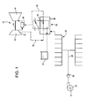
FIGURE 1 is a schematic diagram of a gas turbine combustor and related fuel piping and valves, including a three-way purge valve; -
FIGURE 2 is a perspective view of a three-way purge valve housing assembly in accordance with the invention; and -
FIGURE 3 is a partially exploded view of the housing ofFigure 2 , but with a three-way purge valve shown received within the housing. - With reference initially to
Figure 1 , agas turbine 10 typically includes acompressor 12 and aturbine 14 mounted on asingle shaft 16. Acombustor 18 is arranged to bum a fuel air mixture and to supply the hot gaseous products of combustion to theturbine 14. A three-way purge valve 20 is arranged to supply either liquid or purge to thecombustor 18. Liquid fuel is supplied to the purge valve from aliquid fuel source 22 while purge air is supplied to thevalve 20 by means of ablower 24, acheck valve 26,supply conduit 28 and amanifold 29. The purge air is used when liquid fuel is not flowing (for example, when natural gas fuel is being used) to keep the liquid fuel nozzles cool (and thus prevent coking) and to prevent backflow. - In the exemplary but nonlimiting embodiment described herein, the invention relates particularly to an apparatus for use in cooling the three-
way purge valve 20. Acooling housing 30 is designed for easy installation about thepurge valve 20. Specifically, and with reference also toFigures 2 and3 , the housing (or housing body) 30 is comprised of a generally mailbox-shaped (or other suitably-shaped) structure that includes two half-housing portions seam 36 along the top surface thereof (a similar seam along thebottom surface 38 is not visible). Upstandingtab pairs housing portions 32, 34 (top and bottom) permit easy securement of the half-housing portions by means of screws or other appropriate fasteners. Aforward end plate 44 and a similarrearward end plate 46 are designed to close the ends of the hollow housing body and, here again,similar tab pairs end plates housing body 30. Of course, other equivalent fastening techniques could be employed. - The
forward end plate 44 is also provided with elongated and substantially parallel guide arms 52 (one shown) that are adapted to slide withinopen slots 54 formed on opposite sides of thehousing body 30 and which permit theend plate 44 to be pulled away from thehousing body 30 and removed as shown inFigure 3 . Thus, with theend plates half portions housing portions seam 36. In addition, theend plate 46 could also be provided with guide arms similar to guidearms 52 if so desired. Other equivalent guide devices having a similar function could be employed as well. - As shown in
Figure 3 , the housing may be closed about thepurge valve 20, with inlets and/or outlets of the purge valve accommodated by openings orapertures seam 36. More specifically, these apertures receiverespective fittings housing body 30. Theend plate 44 is reattached by aligning theguide arms 52 with theslots 54 and moving the plate axially into the position shown inFigure 2 . Theend plates tab pairs - A
cooling outlet opening 68 is formed in theend plate 44, and a similarcooling inlet opening 70 is formed in theopposite end plate 46. With thepurge valve 20 seated within the housing, and with the half-housing portions rearward end plates housing body 30 viainlet opening 70, for example, utilizing a take-off 72 (Figure 1 ) to supply compressor air to thehousing 30 by means of a coolingair supply conduit 74 connected to the inlet opening 70 such that cooling air flows through thehousing 30 to cool the threeway purge valve 20, and out of the housing via conduit 64' connected to the outlet opening 68. Alternatively, the purge air may simply exit the outlet opening 68 with no additional piping or conduits required. - Suitable spacers (not shown) of any appropriate size, shape and composition may be used to maintain the
purge valve 20 andhousing body 30 spaced from each other to facilitate efficient cooling flow through the housing. - While the invention has been described in connection with what is presently considered to be the most practical and preferred embodiment, it is to be understood that the invention is not to be limited to the disclosed embodiment, but on the contrary, is intended to cover various modifications and equivalent arrangements included within the scope of the appended claims.
Claims (9)
- A cooling enclosure for a valve (20) comprising:an elongated housing body (30) having a pair of housing portions (32, 34) and a pair of removable end plates (44, 46), said pair of housing portions separable along at least one longitudinally-extending seam (36);means (40, 42) for securing said pair of housing portions engaged along said at least one longitudinal extending seam;one or more apertures (56, 58, 60) for accommodating a like number of valve fittings; andcooling air inlet and outlet openings (70, 68) in said housing body for supplying and removing cooling air to said housing body, wherein at least one of said pair of removable end plates (44, 46) is provided with at least one guide arm (52) receivable in a slot (54) formed in one of said pair of housing portions (32, 34).
- The cooling enclosure of claim 1 wherein said pair of housing portions are separable also along a second longitudinally-extending seam (36).
- The cooling enclosure of claim 2 wherein said at least one and said second longitudinally-extending seams (36) are located along respective top and bottom surfaces of said pair of housing portions (32, 34).
- The cooling enclosure of claim 1 comprising means (48, 50) for securing said pair of removable end plates to said housing body.
- The cooling enclosure of claim 1 wherein at least one of said removable end plates (44) is provided with a pair of axially-extending guide arms (52) receivable within slots (54) formed in said pair of housing portions (32, 34).
- The cooling enclosure of claim 1 wherein said one or more apertures (56, 58, 60) are located along said at least one longitudinally-extending seam (36).
- The cooling enclosure of claim 1 wherein said cooling air inlet and outlet openings (70, 68) are located respectively in said pair of removable end plates (46, 44).
- A system for cooling a gas turbine fuel component (20) adapted for feeding liquid fuel to at least one combustor (18) located in a high temperature environment to thereby eliminate coking in the fuel component, the system comprising: a cooling enclosure as claimed in claim 1; and
a cooling air supply conduit (74) connected to said cooling air inlet. - The system of claim 8, wherein the fuel component comprises a purge valve (20), and wherein at least one aperture (56) is provided along at least one of said seams, adapted to accommodate at least one fitting (62) of the purge valve (20).
Applications Claiming Priority (1)
| Application Number | Priority Date | Filing Date | Title |
|---|---|---|---|
| US12/289,573 US8528315B2 (en) | 2008-10-30 | 2008-10-30 | Air cooling apparatus for a purge valve |
Publications (2)
| Publication Number | Publication Date |
|---|---|
| EP2182263A1 EP2182263A1 (en) | 2010-05-05 |
| EP2182263B1 true EP2182263B1 (en) | 2012-04-18 |
Family
ID=41581097
Family Applications (1)
| Application Number | Title | Priority Date | Filing Date |
|---|---|---|---|
| EP20090174108 Not-in-force EP2182263B1 (en) | 2008-10-30 | 2009-10-27 | Air cooling apparatus for a purge valve |
Country Status (5)
| Country | Link |
|---|---|
| US (1) | US8528315B2 (en) |
| EP (1) | EP2182263B1 (en) |
| JP (1) | JP2010106839A (en) |
| CN (1) | CN101737166A (en) |
| AT (1) | ATE554324T1 (en) |
Families Citing this family (6)
| Publication number | Priority date | Publication date | Assignee | Title |
|---|---|---|---|---|
| US8340886B2 (en) | 2011-03-07 | 2012-12-25 | General Electric Company | System and method for transitioning between fuel supplies for a combustion system |
| US20130283815A1 (en) * | 2012-04-26 | 2013-10-31 | Hamilton Sundstrand Corporation | Integral cooling for servo valve |
| US20130305728A1 (en) * | 2012-05-15 | 2013-11-21 | General Electric Company | Systems and Methods for Minimizing Coking in Gas Turbine Engines |
| FR2994943B1 (en) * | 2012-08-30 | 2014-09-12 | Turbomeca | DRAINING METHOD AND PURGE COLLECTOR FOR CARBURIZING CIRCUIT OF A HELICOPTER |
| CN104373220A (en) * | 2013-08-15 | 2015-02-25 | 西门子公司 | Purge system for gas turbine, and method thereof |
| US11473276B2 (en) * | 2018-09-27 | 2022-10-18 | Sioux Chief Mfg. Co., Inc. | Plumbing service box installation |
Family Cites Families (17)
| Publication number | Priority date | Publication date | Assignee | Title |
|---|---|---|---|---|
| US2732227A (en) * | 1956-01-24 | Welded enclosure for expansion joint | ||
| US2785697A (en) * | 1952-02-18 | 1957-03-19 | Diamond Alkali Co | Valve |
| US3973585A (en) * | 1973-08-14 | 1976-08-10 | Controls Southeast, Inc. | Jacket construction for fluid flow fittings |
| US3901269A (en) * | 1973-08-14 | 1975-08-26 | Controls Southeast Inc | Jacket construction for fluid flow fittings |
| US4017102A (en) * | 1975-06-16 | 1977-04-12 | Controls Southeast, Inc. | Jacket construction for pipe coupling |
| HU185347B (en) | 1982-07-28 | 1985-01-28 | Ipari Szerelveny & Gepgyar | Heating jacket globe valve |
| US4583570A (en) * | 1984-10-15 | 1986-04-22 | Foster Wheeler Energy Corporation | Liquid cooled ball valve |
| DE8709109U1 (en) | 1987-07-01 | 1987-11-05 | Chemat GmbH Armaturen für Industrie- und Nuklearanlagen, 7592 Renchen | Heating jacket |
| US6050081A (en) * | 1997-02-12 | 2000-04-18 | Jansens Aircraft Systems Controls | Air purging fuel valve for turbine engine |
| US6145294A (en) * | 1998-04-09 | 2000-11-14 | General Electric Co. | Liquid fuel and water injection purge system for a gas turbine |
| US6438963B1 (en) * | 2000-08-31 | 2002-08-27 | General Electric Company | Liquid fuel and water injection purge systems and method for a gas turbine having a three-way purge valve |
| US7527068B2 (en) * | 2002-06-18 | 2009-05-05 | Jansen's Aircraft Systems Controls, Inc. | Valve with swirling coolant |
| US7117675B2 (en) * | 2002-12-03 | 2006-10-10 | General Electric Company | Cooling of liquid fuel components to eliminate coking |
| US6918255B2 (en) * | 2002-12-03 | 2005-07-19 | General Electric Company | Cooling of liquid fuel components to eliminate coking |
| US6898926B2 (en) | 2003-01-31 | 2005-05-31 | General Electric Company | Cooled purging fuel injectors |
| US7178546B2 (en) * | 2004-10-04 | 2007-02-20 | Linelox, Llc | Valve cover |
| US7919733B2 (en) * | 2005-08-09 | 2011-04-05 | Watlow Electric Manufacturing Company | Modular heater systems |
-
2008
- 2008-10-30 US US12/289,573 patent/US8528315B2/en active Active
-
2009
- 2009-10-27 EP EP20090174108 patent/EP2182263B1/en not_active Not-in-force
- 2009-10-27 AT AT09174108T patent/ATE554324T1/en active
- 2009-10-28 JP JP2009247174A patent/JP2010106839A/en active Pending
- 2009-10-30 CN CN200910208867A patent/CN101737166A/en active Pending
Also Published As
| Publication number | Publication date |
|---|---|
| ATE554324T1 (en) | 2012-05-15 |
| US20100107640A1 (en) | 2010-05-06 |
| JP2010106839A (en) | 2010-05-13 |
| US8528315B2 (en) | 2013-09-10 |
| EP2182263A1 (en) | 2010-05-05 |
| CN101737166A (en) | 2010-06-16 |
Similar Documents
| Publication | Publication Date | Title |
|---|---|---|
| US8528315B2 (en) | Air cooling apparatus for a purge valve | |
| US20200025086A1 (en) | Cross-stream heat exchanger | |
| US9739198B2 (en) | Oil and fuel circuits in a turbine engine | |
| US7997062B2 (en) | Dual channel regulated fuel-oil heat exchanger | |
| EP3473833B1 (en) | Ice protection system for aircraft engine nacelle | |
| EP1988267B1 (en) | Fuel supply system | |
| US9759130B2 (en) | Gas turbine engine with cooling system | |
| TW345608B (en) | A system for pre-heating fuel in a gas turbine engine | |
| CN108369006B (en) | combustion device | |
| CA2790381A1 (en) | Deicing device for wing leading edge of aircraft and aircraft main wing | |
| US7117675B2 (en) | Cooling of liquid fuel components to eliminate coking | |
| GB2457073A (en) | Modulating cooling airflows | |
| GB0704316D0 (en) | Thermal anti-icing system | |
| WO2009095257A3 (en) | Wing-propulsion unit combination, airplane and wing section of an airplane comprising a propulsion unit tap air channel arrangement | |
| US6918255B2 (en) | Cooling of liquid fuel components to eliminate coking | |
| CN109882293A (en) | The hydraulic and Pneumatic control circuit with fuel/air mixture heat exchanger of turbojet | |
| FR2859664B1 (en) | ADVANCED AEROTHERMAL MANAGEMENT IN A DEVICE FOR HEATING AND / OR AIR CONDITIONING OF A CABINET | |
| EP1593911B1 (en) | Air and fuel delivery system for a post combustor burning ring | |
| US10823068B2 (en) | Heat exchanger device for an aircraft engine | |
| AU2017304849A1 (en) | Heating and hot water supplying device | |
| UA79738C2 (en) | Shutoff device for coal dust burners of a combustion apparatus | |
| EP2580447B1 (en) | Cooling system for controlling cooling of rotor cooling air and heating of fuel gas | |
| US7954324B2 (en) | Gas turbine engine | |
| CN222179835U (en) | Hot air inlet device and aircraft | |
| US20260002694A1 (en) | Heat exchanger arrangement for securing to an appliance wall |
Legal Events
| Date | Code | Title | Description |
|---|---|---|---|
| PUAI | Public reference made under article 153(3) epc to a published international application that has entered the european phase |
Free format text: ORIGINAL CODE: 0009012 |
|
| AK | Designated contracting states |
Kind code of ref document: A1 Designated state(s): AT BE BG CH CY CZ DE DK EE ES FI FR GB GR HR HU IE IS IT LI LT LU LV MC MK MT NL NO PL PT RO SE SI SK SM TR |
|
| AX | Request for extension of the european patent |
Extension state: AL BA RS |
|
| 17P | Request for examination filed |
Effective date: 20101105 |
|
| 17Q | First examination report despatched |
Effective date: 20101130 |
|
| GRAP | Despatch of communication of intention to grant a patent |
Free format text: ORIGINAL CODE: EPIDOSNIGR1 |
|
| GRAS | Grant fee paid |
Free format text: ORIGINAL CODE: EPIDOSNIGR3 |
|
| GRAA | (expected) grant |
Free format text: ORIGINAL CODE: 0009210 |
|
| AK | Designated contracting states |
Kind code of ref document: B1 Designated state(s): AT BE BG CH CY CZ DE DK EE ES FI FR GB GR HR HU IE IS IT LI LT LU LV MC MK MT NL NO PL PT RO SE SI SK SM TR |
|
| REG | Reference to a national code |
Ref country code: GB Ref legal event code: FG4D |
|
| REG | Reference to a national code |
Ref country code: CH Ref legal event code: EP |
|
| REG | Reference to a national code |
Ref country code: IE Ref legal event code: FG4D |
|
| REG | Reference to a national code |
Ref country code: AT Ref legal event code: REF Ref document number: 554324 Country of ref document: AT Kind code of ref document: T Effective date: 20120515 |
|
| REG | Reference to a national code |
Ref country code: CH Ref legal event code: NV Representative=s name: SERVOPATENT GMBH |
|
| REG | Reference to a national code |
Ref country code: DE Ref legal event code: R096 Ref document number: 602009006394 Country of ref document: DE Effective date: 20120614 |
|
| REG | Reference to a national code |
Ref country code: NL Ref legal event code: VDEP Effective date: 20120418 |
|
| REG | Reference to a national code |
Ref country code: AT Ref legal event code: MK05 Ref document number: 554324 Country of ref document: AT Kind code of ref document: T Effective date: 20120418 |
|
| LTIE | Lt: invalidation of european patent or patent extension |
Effective date: 20120418 |
|
| PG25 | Lapsed in a contracting state [announced via postgrant information from national office to epo] |
Ref country code: PL Free format text: LAPSE BECAUSE OF FAILURE TO SUBMIT A TRANSLATION OF THE DESCRIPTION OR TO PAY THE FEE WITHIN THE PRESCRIBED TIME-LIMIT Effective date: 20120418 Ref country code: NO Free format text: LAPSE BECAUSE OF FAILURE TO SUBMIT A TRANSLATION OF THE DESCRIPTION OR TO PAY THE FEE WITHIN THE PRESCRIBED TIME-LIMIT Effective date: 20120718 Ref country code: LT Free format text: LAPSE BECAUSE OF FAILURE TO SUBMIT A TRANSLATION OF THE DESCRIPTION OR TO PAY THE FEE WITHIN THE PRESCRIBED TIME-LIMIT Effective date: 20120418 Ref country code: FI Free format text: LAPSE BECAUSE OF FAILURE TO SUBMIT A TRANSLATION OF THE DESCRIPTION OR TO PAY THE FEE WITHIN THE PRESCRIBED TIME-LIMIT Effective date: 20120418 Ref country code: IS Free format text: LAPSE BECAUSE OF FAILURE TO SUBMIT A TRANSLATION OF THE DESCRIPTION OR TO PAY THE FEE WITHIN THE PRESCRIBED TIME-LIMIT Effective date: 20120818 Ref country code: SE Free format text: LAPSE BECAUSE OF FAILURE TO SUBMIT A TRANSLATION OF THE DESCRIPTION OR TO PAY THE FEE WITHIN THE PRESCRIBED TIME-LIMIT Effective date: 20120418 Ref country code: CY Free format text: LAPSE BECAUSE OF FAILURE TO SUBMIT A TRANSLATION OF THE DESCRIPTION OR TO PAY THE FEE WITHIN THE PRESCRIBED TIME-LIMIT Effective date: 20120418 |
|
| PG25 | Lapsed in a contracting state [announced via postgrant information from national office to epo] |
Ref country code: GR Free format text: LAPSE BECAUSE OF FAILURE TO SUBMIT A TRANSLATION OF THE DESCRIPTION OR TO PAY THE FEE WITHIN THE PRESCRIBED TIME-LIMIT Effective date: 20120719 Ref country code: SI Free format text: LAPSE BECAUSE OF FAILURE TO SUBMIT A TRANSLATION OF THE DESCRIPTION OR TO PAY THE FEE WITHIN THE PRESCRIBED TIME-LIMIT Effective date: 20120418 Ref country code: PT Free format text: LAPSE BECAUSE OF FAILURE TO SUBMIT A TRANSLATION OF THE DESCRIPTION OR TO PAY THE FEE WITHIN THE PRESCRIBED TIME-LIMIT Effective date: 20120820 Ref country code: LV Free format text: LAPSE BECAUSE OF FAILURE TO SUBMIT A TRANSLATION OF THE DESCRIPTION OR TO PAY THE FEE WITHIN THE PRESCRIBED TIME-LIMIT Effective date: 20120418 Ref country code: HR Free format text: LAPSE BECAUSE OF FAILURE TO SUBMIT A TRANSLATION OF THE DESCRIPTION OR TO PAY THE FEE WITHIN THE PRESCRIBED TIME-LIMIT Effective date: 20120418 |
|
| PG25 | Lapsed in a contracting state [announced via postgrant information from national office to epo] |
Ref country code: BE Free format text: LAPSE BECAUSE OF FAILURE TO SUBMIT A TRANSLATION OF THE DESCRIPTION OR TO PAY THE FEE WITHIN THE PRESCRIBED TIME-LIMIT Effective date: 20120418 |
|
| PG25 | Lapsed in a contracting state [announced via postgrant information from national office to epo] |
Ref country code: CZ Free format text: LAPSE BECAUSE OF FAILURE TO SUBMIT A TRANSLATION OF THE DESCRIPTION OR TO PAY THE FEE WITHIN THE PRESCRIBED TIME-LIMIT Effective date: 20120418 Ref country code: SK Free format text: LAPSE BECAUSE OF FAILURE TO SUBMIT A TRANSLATION OF THE DESCRIPTION OR TO PAY THE FEE WITHIN THE PRESCRIBED TIME-LIMIT Effective date: 20120418 Ref country code: RO Free format text: LAPSE BECAUSE OF FAILURE TO SUBMIT A TRANSLATION OF THE DESCRIPTION OR TO PAY THE FEE WITHIN THE PRESCRIBED TIME-LIMIT Effective date: 20120418 Ref country code: EE Free format text: LAPSE BECAUSE OF FAILURE TO SUBMIT A TRANSLATION OF THE DESCRIPTION OR TO PAY THE FEE WITHIN THE PRESCRIBED TIME-LIMIT Effective date: 20120418 Ref country code: NL Free format text: LAPSE BECAUSE OF FAILURE TO SUBMIT A TRANSLATION OF THE DESCRIPTION OR TO PAY THE FEE WITHIN THE PRESCRIBED TIME-LIMIT Effective date: 20120418 Ref country code: AT Free format text: LAPSE BECAUSE OF FAILURE TO SUBMIT A TRANSLATION OF THE DESCRIPTION OR TO PAY THE FEE WITHIN THE PRESCRIBED TIME-LIMIT Effective date: 20120418 Ref country code: DK Free format text: LAPSE BECAUSE OF FAILURE TO SUBMIT A TRANSLATION OF THE DESCRIPTION OR TO PAY THE FEE WITHIN THE PRESCRIBED TIME-LIMIT Effective date: 20120418 |
|
| PGFP | Annual fee paid to national office [announced via postgrant information from national office to epo] |
Ref country code: DE Payment date: 20121029 Year of fee payment: 4 |
|
| PLBE | No opposition filed within time limit |
Free format text: ORIGINAL CODE: 0009261 |
|
| STAA | Information on the status of an ep patent application or granted ep patent |
Free format text: STATUS: NO OPPOSITION FILED WITHIN TIME LIMIT |
|
| PG25 | Lapsed in a contracting state [announced via postgrant information from national office to epo] |
Ref country code: IT Free format text: LAPSE BECAUSE OF FAILURE TO SUBMIT A TRANSLATION OF THE DESCRIPTION OR TO PAY THE FEE WITHIN THE PRESCRIBED TIME-LIMIT Effective date: 20120418 |
|
| 26N | No opposition filed |
Effective date: 20130121 |
|
| PG25 | Lapsed in a contracting state [announced via postgrant information from national office to epo] |
Ref country code: ES Free format text: LAPSE BECAUSE OF FAILURE TO SUBMIT A TRANSLATION OF THE DESCRIPTION OR TO PAY THE FEE WITHIN THE PRESCRIBED TIME-LIMIT Effective date: 20120729 |
|
| REG | Reference to a national code |
Ref country code: DE Ref legal event code: R097 Ref document number: 602009006394 Country of ref document: DE Effective date: 20130121 |
|
| PG25 | Lapsed in a contracting state [announced via postgrant information from national office to epo] |
Ref country code: MC Free format text: LAPSE BECAUSE OF NON-PAYMENT OF DUE FEES Effective date: 20121031 |
|
| REG | Reference to a national code |
Ref country code: FR Ref legal event code: ST Effective date: 20130628 |
|
| PG25 | Lapsed in a contracting state [announced via postgrant information from national office to epo] |
Ref country code: BG Free format text: LAPSE BECAUSE OF FAILURE TO SUBMIT A TRANSLATION OF THE DESCRIPTION OR TO PAY THE FEE WITHIN THE PRESCRIBED TIME-LIMIT Effective date: 20120718 |
|
| REG | Reference to a national code |
Ref country code: IE Ref legal event code: MM4A |
|
| PG25 | Lapsed in a contracting state [announced via postgrant information from national office to epo] |
Ref country code: FR Free format text: LAPSE BECAUSE OF NON-PAYMENT OF DUE FEES Effective date: 20121031 |
|
| PG25 | Lapsed in a contracting state [announced via postgrant information from national office to epo] |
Ref country code: IE Free format text: LAPSE BECAUSE OF NON-PAYMENT OF DUE FEES Effective date: 20121027 |
|
| PG25 | Lapsed in a contracting state [announced via postgrant information from national office to epo] |
Ref country code: MT Free format text: LAPSE BECAUSE OF FAILURE TO SUBMIT A TRANSLATION OF THE DESCRIPTION OR TO PAY THE FEE WITHIN THE PRESCRIBED TIME-LIMIT Effective date: 20120418 |
|
| PG25 | Lapsed in a contracting state [announced via postgrant information from national office to epo] |
Ref country code: TR Free format text: LAPSE BECAUSE OF FAILURE TO SUBMIT A TRANSLATION OF THE DESCRIPTION OR TO PAY THE FEE WITHIN THE PRESCRIBED TIME-LIMIT Effective date: 20120418 |
|
| PG25 | Lapsed in a contracting state [announced via postgrant information from national office to epo] |
Ref country code: LU Free format text: LAPSE BECAUSE OF NON-PAYMENT OF DUE FEES Effective date: 20121027 Ref country code: SM Free format text: LAPSE BECAUSE OF FAILURE TO SUBMIT A TRANSLATION OF THE DESCRIPTION OR TO PAY THE FEE WITHIN THE PRESCRIBED TIME-LIMIT Effective date: 20120418 |
|
| REG | Reference to a national code |
Ref country code: CH Ref legal event code: PL |
|
| GBPC | Gb: european patent ceased through non-payment of renewal fee |
Effective date: 20131027 |
|
| REG | Reference to a national code |
Ref country code: DE Ref legal event code: R119 Ref document number: 602009006394 Country of ref document: DE Effective date: 20140501 |
|
| PG25 | Lapsed in a contracting state [announced via postgrant information from national office to epo] |
Ref country code: CH Free format text: LAPSE BECAUSE OF NON-PAYMENT OF DUE FEES Effective date: 20131031 Ref country code: LI Free format text: LAPSE BECAUSE OF NON-PAYMENT OF DUE FEES Effective date: 20131031 Ref country code: HU Free format text: LAPSE BECAUSE OF FAILURE TO SUBMIT A TRANSLATION OF THE DESCRIPTION OR TO PAY THE FEE WITHIN THE PRESCRIBED TIME-LIMIT Effective date: 20091027 Ref country code: GB Free format text: LAPSE BECAUSE OF NON-PAYMENT OF DUE FEES Effective date: 20131027 |
|
| PG25 | Lapsed in a contracting state [announced via postgrant information from national office to epo] |
Ref country code: DE Free format text: LAPSE BECAUSE OF NON-PAYMENT OF DUE FEES Effective date: 20140501 |
|
| PG25 | Lapsed in a contracting state [announced via postgrant information from national office to epo] |
Ref country code: MK Free format text: LAPSE BECAUSE OF FAILURE TO SUBMIT A TRANSLATION OF THE DESCRIPTION OR TO PAY THE FEE WITHIN THE PRESCRIBED TIME-LIMIT Effective date: 20120418 |