EP2182206A2 - Hydraulic sytem and wind turbine generator provided therewith - Google Patents
Hydraulic sytem and wind turbine generator provided therewith Download PDFInfo
- Publication number
- EP2182206A2 EP2182206A2 EP20090174364 EP09174364A EP2182206A2 EP 2182206 A2 EP2182206 A2 EP 2182206A2 EP 20090174364 EP20090174364 EP 20090174364 EP 09174364 A EP09174364 A EP 09174364A EP 2182206 A2 EP2182206 A2 EP 2182206A2
- Authority
- EP
- European Patent Office
- Prior art keywords
- hydraulic
- oil
- flow rate
- bypass path
- temperature
- Prior art date
- Legal status (The legal status is an assumption and is not a legal conclusion. Google has not performed a legal analysis and makes no representation as to the accuracy of the status listed.)
- Withdrawn
Links
- 238000001514 detection method Methods 0.000 claims abstract description 27
- 239000003921 oil Substances 0.000 description 41
- 238000010586 diagram Methods 0.000 description 5
- 238000009434 installation Methods 0.000 description 4
- 239000007858 starting material Substances 0.000 description 4
- 238000010248 power generation Methods 0.000 description 3
- 239000010720 hydraulic oil Substances 0.000 description 1
- 239000000463 material Substances 0.000 description 1
- 238000000034 method Methods 0.000 description 1
Images



Classifications
-
- F—MECHANICAL ENGINEERING; LIGHTING; HEATING; WEAPONS; BLASTING
- F03—MACHINES OR ENGINES FOR LIQUIDS; WIND, SPRING, OR WEIGHT MOTORS; PRODUCING MECHANICAL POWER OR A REACTIVE PROPULSIVE THRUST, NOT OTHERWISE PROVIDED FOR
- F03D—WIND MOTORS
- F03D7/00—Controlling wind motors
- F03D7/02—Controlling wind motors the wind motors having rotation axis substantially parallel to the air flow entering the rotor
-
- F—MECHANICAL ENGINEERING; LIGHTING; HEATING; WEAPONS; BLASTING
- F03—MACHINES OR ENGINES FOR LIQUIDS; WIND, SPRING, OR WEIGHT MOTORS; PRODUCING MECHANICAL POWER OR A REACTIVE PROPULSIVE THRUST, NOT OTHERWISE PROVIDED FOR
- F03D—WIND MOTORS
- F03D9/00—Adaptations of wind motors for special use; Combinations of wind motors with apparatus driven thereby; Wind motors specially adapted for installation in particular locations
-
- F—MECHANICAL ENGINEERING; LIGHTING; HEATING; WEAPONS; BLASTING
- F03—MACHINES OR ENGINES FOR LIQUIDS; WIND, SPRING, OR WEIGHT MOTORS; PRODUCING MECHANICAL POWER OR A REACTIVE PROPULSIVE THRUST, NOT OTHERWISE PROVIDED FOR
- F03D—WIND MOTORS
- F03D9/00—Adaptations of wind motors for special use; Combinations of wind motors with apparatus driven thereby; Wind motors specially adapted for installation in particular locations
- F03D9/10—Combinations of wind motors with apparatus storing energy
-
- Y—GENERAL TAGGING OF NEW TECHNOLOGICAL DEVELOPMENTS; GENERAL TAGGING OF CROSS-SECTIONAL TECHNOLOGIES SPANNING OVER SEVERAL SECTIONS OF THE IPC; TECHNICAL SUBJECTS COVERED BY FORMER USPC CROSS-REFERENCE ART COLLECTIONS [XRACs] AND DIGESTS
- Y02—TECHNOLOGIES OR APPLICATIONS FOR MITIGATION OR ADAPTATION AGAINST CLIMATE CHANGE
- Y02E—REDUCTION OF GREENHOUSE GAS [GHG] EMISSIONS, RELATED TO ENERGY GENERATION, TRANSMISSION OR DISTRIBUTION
- Y02E10/00—Energy generation through renewable energy sources
- Y02E10/70—Wind energy
- Y02E10/72—Wind turbines with rotation axis in wind direction
-
- Y—GENERAL TAGGING OF NEW TECHNOLOGICAL DEVELOPMENTS; GENERAL TAGGING OF CROSS-SECTIONAL TECHNOLOGIES SPANNING OVER SEVERAL SECTIONS OF THE IPC; TECHNICAL SUBJECTS COVERED BY FORMER USPC CROSS-REFERENCE ART COLLECTIONS [XRACs] AND DIGESTS
- Y02—TECHNOLOGIES OR APPLICATIONS FOR MITIGATION OR ADAPTATION AGAINST CLIMATE CHANGE
- Y02E—REDUCTION OF GREENHOUSE GAS [GHG] EMISSIONS, RELATED TO ENERGY GENERATION, TRANSMISSION OR DISTRIBUTION
- Y02E70/00—Other energy conversion or management systems reducing GHG emissions
- Y02E70/30—Systems combining energy storage with energy generation of non-fossil origin
-
- Y—GENERAL TAGGING OF NEW TECHNOLOGICAL DEVELOPMENTS; GENERAL TAGGING OF CROSS-SECTIONAL TECHNOLOGIES SPANNING OVER SEVERAL SECTIONS OF THE IPC; TECHNICAL SUBJECTS COVERED BY FORMER USPC CROSS-REFERENCE ART COLLECTIONS [XRACs] AND DIGESTS
- Y02—TECHNOLOGIES OR APPLICATIONS FOR MITIGATION OR ADAPTATION AGAINST CLIMATE CHANGE
- Y02P—CLIMATE CHANGE MITIGATION TECHNOLOGIES IN THE PRODUCTION OR PROCESSING OF GOODS
- Y02P80/00—Climate change mitigation technologies for sector-wide applications
- Y02P80/10—Efficient use of energy, e.g. using compressed air or pressurized fluid as energy carrier
Definitions
- the present invention relates to a hydraulic (actuation) system applied to wind turbine blade pitch control or the like and adapted to supply oil from a hydraulic tank into a hydraulic unit for blade pitch control (hydraulic actuation system such as a hydraulic cylinder) through a hydraulic main line by means of a hydraulic pump placed in the hydraulic main line in order to actuate the hydraulic unit with the oil, and a wind turbine generator provided therewith.
- actuation applied to wind turbine blade pitch control or the like and adapted to supply oil from a hydraulic tank into a hydraulic unit for blade pitch control (hydraulic actuation system such as a hydraulic cylinder) through a hydraulic main line by means of a hydraulic pump placed in the hydraulic main line in order to actuate the hydraulic unit with the oil, and a wind turbine generator provided therewith.
- FIG. 6 shows the outline of a hydraulic (actuation) system of a hydraulic unit for wind turbine blade pitch actuation, in which the hydraulic unit for blade pitch actuation designated by reference numeral 1 is supplied with oil 15 stored in a hydraulic tank 14 through a hydraulic main line 8.
- a hydraulic pump 4 to be driven by a motor 5 is placed in the hydraulic main line 8, and the oil 15 in the hydraulic tank 14 is fed by the hydraulic pump 4 into the hydraulic unit 1 through the hydraulic main line 8.
- a check valve 16 capable of feeding oil only on the side of the hydraulic unit 1 is provided in the hydraulic main line 8.
- a heater 30 is placed to warm the oil 15 stored in the hydraulic tank 14.
- the temperature of the oil 15 in the hydraulic tank 14 is detected by a temperature sensor 7.
- the method using such a conventional heater 30 takes three to four hours to rise the oil temperature from -30 degrees C to -10 degrees C at startup, for example, thus requiring a lot of time and the installation cost of the heater 30.
- Patent Document 1 Japanese Examined Utility Model Application Publication No. 61-23520 shows a hydraulic system adapted to open a logic valve (bypassed state) upon startup of a hydraulic pump in a hydraulic system for a steering gear and close the logic valve when the hydraulic pump reaches the steady rotation.
- a hydraulic system hydraulic actuation system such as a hydraulic cylinder
- a wind turbine generator provided therewith.
- the present invention has been made to attain such an object by comprising: a bypass path branching off from the discharge side of the hydraulic pump in the hydraulic main line into the hydraulic tank and flow rate control means provided in the bypass path to control the flow rate of the bypass path; a pressure sensor provided in an inlet of the hydraulic unit in the hydraulic main line; and a control device to which a pressure detection value is input from the pressure sensor to control the flow rate control means based on the pressure detection value, wherein oil is circulated in the bypass path while keeping the pump discharge pressure and the flow rate equal to or smaller than given specified values.
- the flow rate control means be a bypass valve that opens or closes the bypass path.
- the flow rate control means be a variable flow valve that controls the oil flow rate of the bypass path.
- the structure comprises: the bypass path branching off from the discharge side of the hydraulic pump in the hydraulic main line into the hydraulic tank and flow rate control means provided in the bypass path to control the flow rate of the bypass path; the pressure sensor provided in the inlet of the hydraulic unit in the hydraulic main line; and the control device to which the pressure detection value is input from the pressure sensor to control the flow rate control means based on the pressure detection value.
- oil is circulated in the bypass path while keeping the pump discharge pressure and the flow rate equal to or smaller than the given specified values.
- control device receives a pressure detection signal upon startup of the hydraulic system, performs so-called PWM control to turn on/off a pulse controlled bypass valve so that the pump power of the hydraulic unit will become the maximum in order to rise oil temperature in the hydraulic main line on the hydraulic pump discharge side, and further controls the pump discharge pressure and the flow rate to be equal to or smaller than preset specified values. This enables an operation at the maximum pump power value or smaller at all times, and hence oil temperature can rise efficiently.
- the present invention comprises a variable flow valve in the bypass path, wherein the control device controls the bypass flow rate using the variable flow valve to rise the temperature, so that flow rate control can be performed by a flow restrictor of the variable flow valve at a set point with the maximum pump power value or smaller at all times while detecting pressure in the hydraulic main line by means of the pressure sensor, thereby enabling a stable operation at the maximum pump power at all times, oil temperature to rise efficiently, and low-temperature startup in a relatively short time. Therefore, high installation costs conventionally required for components such as the heater are not needed, resulting in a reduction in the device cost.
- the temperature sensor for detecting the temperature of the oil and inputting the temperature detection value to the control device, wherein when the temperature detection value is lower than a predetermined temperature, the control device circulates oil in the bypass path while controlling the flow rate control means, and when the temperature detection value reaches the predetermined temperature, the control device performs control to stop oil circulation in the bypass path.
- the bypass path is closed to apply pressure to the hydraulic main line, enabling the normal operation.
- the hydraulic main line denotes a hydraulic line that guides hydraulic oil from the hydraulic tank to the hydraulic unit by means of the hydraulic pump.
- the hydraulic system of the present invention is suitable for a wind turbine generator provided with a hydraulic system for wind turbine blade pitch actuation, especially for a wind turbine generator using a hydraulic pump of the hydraulic system in cold climates reaching about -30 degrees C.
- FIG. 1 is a system diagram of a starter in a hydraulic system for wind turbine blade pitch actuation according to a first embodiment of the present invention.
- a hydraulic unit for blade pitch actuation (hydraulic actuation system such as a hydraulic cylinder) designated by reference numeral 1 is supplied with oil 15 stored in a hydraulic tank 14 through a hydraulic main line 8.
- a hydraulic pump 4 to be driven by a motor 5 is placed in the hydraulic main line 8, and the oil 15 in the hydraulic tank 14 is fed by the hydraulic pump 4 into the hydraulic unit 1 through the hydraulic main line 8.
- a check valve 16 capable of feeding oil only on the side of the hydraulic unit 1 is provided in the hydraulic main line 8 (where a proportional valve, not shown, is provided in the inlet of the check valve 16 to prevent oil from flowing into a cylinder of the hydraulic unit when a bypass valve 3 is turned off).
- a proportional valve not shown, is provided in the inlet of the check valve 16 to prevent oil from flowing into a cylinder of the hydraulic unit when a bypass valve 3 is turned off.
- an air breather provided in the hydraulic tank 14 is designated by reference numeral 6.
- the bypass valve 3 is turned on/off by a pulse control signal from a control device 10 to perform PWM control.
- the PWM control i.e., on/off cycle control, can make it easy to control quantity/pressure of oil flowing through the bypass path 19, so that the maximum load operation of the hydraulic pump 4 can be controlled, and hence the heat of oil resulting from the action of the hydraulic pump 4 can be effectively used to rise oil temperature.
- the pressure of oil to be bypassed and the bypass flow rate can be effectively used to control the generation of heat by the action of the hydraulic pump 4 and further a rise of oil temperature caused by a pulsed pressure change in oil flow in the bypass path.
- a pressure detection signal from the pressure sensor 2 is input to the control device 10 through a line 11. Further, a temperature sensor 7 for detecting the temperature of oil is provided in the hydraulic main line 8 or the hydraulic tank 14 (in this embodiment, it is provided in the hydraulic tank 14), and a temperature detection signal of the temperature sensor 7 is input to the control device 10 through a line 13.
- a control value based on the pressure detection signal and the temperature detection signal is input to the control device 10 through a line 12 to control on/off of the bypass valve 3.
- a set curve of actuation power of the hydraulic unit 1 is in a relationship (on a map) between pressure and flow rate.
- Such a relationship (map) is set in a maximum actuation power setting section 30, and Po set value in the maximum actuation power setting section 30 is input to the control device 10.
- the maximum actuation power is a power value at which "pressurexflow rate" becomes the maximum (where the pressure value at that time is expressed by po).
- FIG. 3 is a flowchart showing the operation of the first embodiment.
- the bypass valve 3 Upon startup of the hydraulic unit 1, the bypass valve 3 is first opened to open the bypass path 19 (step (1)), and from the pressure of the pressure sensor 2, it is confirmed that there is no load in the hydraulic main line 8 (on the discharge side of the hydraulic pump 4, especially between the check valve 16 and the inlet of the hydraulic unit 1 (step (2)). Next, from the pressure of the pressure sensor 2, it is determined whether the pressure in the hydraulic main line 8 reaches 0 Mpa (step (3)), and after that, the motor 5 is driven (step (4)).
- the pressure detection signal from the pressure sensor 2 is received while bypassing the oil to the bypass path 19 before the check valve 16 on the discharge side of the hydraulic pump 4 and circulating it between the pressure sensor 2 and the tank 14 to perform PWM control while turning on/off the bypass valve 3 according to the pulse control signal from the control device 10 so that the pressure value Po in the maximum actuation power ("pressurexflow rate") will become the maximum (step (5)).
- pressurexflow rate the pressure value Po in the maximum actuation power
- PWM control is performed while turning on/off the bypass valve 3, so that control is so performed that flow ratexpressure in FIG. 5 will become the maximum, i.e., the maximum value of pump power (preset specified pressure P0 and flow rate).
- the temperature sensor 7 for detecting the temperature of oil is provided in the hydraulic main line 8 or the hydraulic tank 14 (in this embodiment, it is provided in the hydraulic tank 14), and the temperature detection signal of the temperature sensor 7 is input to the control device 10 through the line 13.
- the temperature from the temperature sensor 7, i.e., the temperature of the temperature sensor 7 provided in the hydraulic main line 8 or the hydraulic tank 14 (in this embodiment, it is provided in the hydraulic tank 14) is checked by the control device 10 (step (8)). If the temperature reaches the lowest actuation temperature (e.g., -10 degrees C) of the hydraulic system (step (9)), the bypass valve 3 is closed to apply pressure (load) from the hydraulic main line 8 to the hydraulic unit 1 through the check valve 16.
- the lowest actuation temperature e.g., -10 degrees C
- the pressure detection signal from the pressure sensor 2 is received after startup of the hydraulic system to perform PWM control to turn on/off the pulse controlled bypass valve 3 so that the pump power (flow rate) of the hydraulic pump 4 will become the maximum.
- the bypass valve 3 is controlled to operate in pulses to perform PWM control while turning on/off the bypass valve 3, so that the bypass operation is performed under the control of the specified pressure P0 to maximize the pump power (Po). Heat received upon this pump actuation can rise oil temperature effectively.
- PWM control is performed on the bypass valve 3 turned on/off by pulse control to achieve the bypass operation at the maximum value of actuation power (flow rate).
- actuation power flow rate
- the bypass valve 3 is closed, while when it does not reach the predetermined actuation temperature, the bypass valve 3 is opened to repeat the bypass operation at the maximum value of actuation power (flow rate).
- the bypass valve 3 is closed to apply pressure to the hydraulic main line 8, so that the normal operation can be performed.
- the embodiment can significantly reduce the warm-up time before running the hydraulic system for wind turbine blade pitch actuation. This may also be applied to a wind turbine hydraulic system other than the hydraulic system for wind turbine blade pitch actuation.
- Such a hydraulic circuit like in this embodiment can make it easy to adjust the warm-up time compared to other components (bearing, etc.) of the wind turbine, enabling efficient warm-up.
- FIG. 2 is a system diagram of a starter in a hydraulic system for wind turbine blade pitch actuation according to a second embodiment of the present invention.
- This second embodiment differs from the first embodiment in that a variable flow valve 31 is provided in the bypass path 19 to make the flow restriction in the bypass path 19 variable.
- step (5) is different from that in the first embodiment, and the other steps are the same.
- step (5) a pressure detection signal from the pressure sensor 2 is received after startup of the hydraulic system to change the amount of flow restriction (throttle) of the variable flow valve 31 in the hydraulic unit 1 in order to control flow path resistance of the bypass path 19.
- the throttle of the variable flow valve 31 can be so controlled that the optimum flow rate is settable by the throttle at the set point with the maximum value of actuation power or smaller.
- the bypass flow rate is controlled by the throttle to be located at the point (specified pressure P0) on the preset maximum power generation line while detecting pressure in the hydraulic main line 8 using the pressure sensor 2 in the hydraulic main line 8, so that an operation at the maximum power output point of the hydraulic pump, i.e., an operation at the maximum point of calorific power can be achieved.
- This can maintain a stable operation at the maximum value of actuation power.
- a hydraulic pump startup control device in a hydraulic system which avoids an overloaded state at startup to enable low-temperature, fast startup and maintaining of the temperature with low-cost means in order to improve low-temperature startability, and a wind turbine generator provided therewith.
- the bypass operation may be performed as long as it does not interfere with blade pitch actuation to maintain the oil temperature at the lowest actuation temperature or higher.
Landscapes
- Engineering & Computer Science (AREA)
- Life Sciences & Earth Sciences (AREA)
- Sustainable Development (AREA)
- Sustainable Energy (AREA)
- Chemical & Material Sciences (AREA)
- Combustion & Propulsion (AREA)
- Mechanical Engineering (AREA)
- General Engineering & Computer Science (AREA)
- Power Engineering (AREA)
- Fluid-Pressure Circuits (AREA)
- Wind Motors (AREA)
Abstract
There is provided a hydraulic pump startup control device in a hydraulic system. A bypass path (19) is placed in parallel with a hydraulic main line from a hydraulic tank, and the downstream of the bypass path is made merged with the hydraulic main line. A bypass valve (3) that opens or closes the bypass path is provided in the bypass path, and a pressure sensor is provided in the inlet of a hydraulic unit in the hydraulic main line. Further, a control device (10) to which a pressure detection value in the hydraulic main line is input from the pressure sensor to open the bypass valve based on the pressure detection value upon startup of the hydraulic unit.
Description
- The present invention relates to a hydraulic (actuation) system applied to wind turbine blade pitch control or the like and adapted to supply oil from a hydraulic tank into a hydraulic unit for blade pitch control (hydraulic actuation system such as a hydraulic cylinder) through a hydraulic main line by means of a hydraulic pump placed in the hydraulic main line in order to actuate the hydraulic unit with the oil, and a wind turbine generator provided therewith.
-
FIG. 6 shows the outline of a hydraulic (actuation) system of a hydraulic unit for wind turbine blade pitch actuation, in which the hydraulic unit for blade pitch actuation designated byreference numeral 1 is supplied withoil 15 stored in ahydraulic tank 14 through a hydraulicmain line 8. - A
hydraulic pump 4 to be driven by amotor 5 is placed in the hydraulicmain line 8, and theoil 15 in thehydraulic tank 14 is fed by thehydraulic pump 4 into thehydraulic unit 1 through the hydraulicmain line 8. Acheck valve 16 capable of feeding oil only on the side of thehydraulic unit 1 is provided in the hydraulicmain line 8. - In such a hydraulic system for blade pitch actuation, if the hydraulic pump of the hydraulic system is used in cold climates reaching about -30 degrees C, the oil temperature has to rise to -10 degrees C or more to prevent damage to the equipment.
- To this end, a
heater 30 is placed to warm theoil 15 stored in thehydraulic tank 14. The temperature of theoil 15 in thehydraulic tank 14 is detected by atemperature sensor 7. - However, the method using such a
conventional heater 30 takes three to four hours to rise the oil temperature from -30 degrees C to -10 degrees C at startup, for example, thus requiring a lot of time and the installation cost of theheater 30. - Patent Document 1 (Japanese Examined Utility Model Application Publication No.
61-23520 - Further, in the hydraulic system for wind turbine blade pitch actuation as shown in
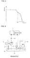
FIG. 6 , if some load is left in the hydraulic system when the hydraulic system (hydraulic pump) is actuated at startup, excess current T flows through amotor 5 suddenly for a short time as shown inFIG. 7 to increase the load on the hydraulic system (hydraulic pump), resulting in an overload. If this overloaded state at startup is repeated, a problem can occur with wind turbine blade pitch or blade control. - In view of such a conventional technical problem, it is an object of the present invention to provide a hydraulic system (hydraulic actuation system such as a hydraulic cylinder), which avoids an overloaded state at startup to enable low-temperature, fast startup and maintaining of the temperature with low-cost means in order to improve low-temperature startability, and a wind turbine generator provided therewith.
- The present invention has been made to attain such an object by comprising: a bypass path branching off from the discharge side of the hydraulic pump in the hydraulic main line into the hydraulic tank and flow rate control means provided in the bypass path to control the flow rate of the bypass path; a pressure sensor provided in an inlet of the hydraulic unit in the hydraulic main line; and a control device to which a pressure detection value is input from the pressure sensor to control the flow rate control means based on the pressure detection value, wherein oil is circulated in the bypass path while keeping the pump discharge pressure and the flow rate equal to or smaller than given specified values.
- In the present invention, it is preferred that the flow rate control means be a bypass valve that opens or closes the bypass path.
- In the present invention, it is also preferred that the flow rate control means be a variable flow valve that controls the oil flow rate of the bypass path.
- In the above invention, it is preferred to further comprise a temperature sensor for detecting the temperature of the oil and inputting a temperature detection value to the control device, wherein when the temperature detection value is lower than a predetermined temperature, the control device circulates the oil in the bypass path while controlling the flow rate control means, and when the temperature detection value reaches the predetermined temperature, the control device performs control to stop oil circulation in the bypass path.
- According to the present invention, the structure comprises: the bypass path branching off from the discharge side of the hydraulic pump in the hydraulic main line into the hydraulic tank and flow rate control means provided in the bypass path to control the flow rate of the bypass path; the pressure sensor provided in the inlet of the hydraulic unit in the hydraulic main line; and the control device to which the pressure detection value is input from the pressure sensor to control the flow rate control means based on the pressure detection value.
- Then, oil is circulated in the bypass path while keeping the pump discharge pressure and the flow rate equal to or smaller than the given specified values.
- Since no load in the hydraulic main line on the hydraulic pump discharge side is confirmed from the pressure of the pressure sensor before startup, an overload that conventionally occurs due to a flow of excess current in the hydraulic pump at startup can be avoided.
- Further, the control device receives a pressure detection signal upon startup of the hydraulic system, performs so-called PWM control to turn on/off a pulse controlled bypass valve so that the pump power of the hydraulic unit will become the maximum in order to rise oil temperature in the hydraulic main line on the hydraulic pump discharge side, and further controls the pump discharge pressure and the flow rate to be equal to or smaller than preset specified values. This enables an operation at the maximum pump power value or smaller at all times, and hence oil temperature can rise efficiently.
- Thus, PWM control to turn on/off the pulse controlled bypass valve is performed, and this enables low-temperature startup in a relatively short time. Therefore, high installation costs conventionally required for components such as the heater are not needed, resulting in a reduction in the device cost.
- Further, the present invention comprises a variable flow valve in the bypass path, wherein the control device controls the bypass flow rate using the variable flow valve to rise the temperature, so that flow rate control can be performed by a flow restrictor of the variable flow valve at a set point with the maximum pump power value or smaller at all times while detecting pressure in the hydraulic main line by means of the pressure sensor, thereby enabling a stable operation at the maximum pump power at all times, oil temperature to rise efficiently, and low-temperature startup in a relatively short time. Therefore, high installation costs conventionally required for components such as the heater are not needed, resulting in a reduction in the device cost.
- Further, in the above invention, the temperature sensor for detecting the temperature of the oil and inputting the temperature detection value to the control device, wherein when the temperature detection value is lower than a predetermined temperature, the control device circulates oil in the bypass path while controlling the flow rate control means, and when the temperature detection value reaches the predetermined temperature, the control device performs control to stop oil circulation in the bypass path. Thus, when the temperature of the hydraulic main line reaches the lowest actuation temperature of the equipment, the bypass path is closed to apply pressure to the hydraulic main line, enabling the normal operation.
- Here, the hydraulic main line denotes a hydraulic line that guides hydraulic oil from the hydraulic tank to the hydraulic unit by means of the hydraulic pump.
- The hydraulic system of the present invention is suitable for a wind turbine generator provided with a hydraulic system for wind turbine blade pitch actuation, especially for a wind turbine generator using a hydraulic pump of the hydraulic system in cold climates reaching about -30 degrees C.
-
-
FIG. 1 is a system diagram of a starter of a hydraulic actuation system in a hydraulic system for wind turbine blade pitch actuation according to a first embodiment of the present invention. -
FIG. 2 is a system diagram of a starter of the hydraulic actuation system in the hydraulic system for wind turbine blade pitch actuation according to a second embodiment of the present invention. -
FIG. 3 is a flowchart showing the operation of the first embodiment of the present invention. -
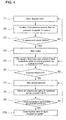
FIG. 4 is a flowchart showing the operation of the second embodiment of the present invention. -
FIG. 5 is a graph showing a set curve of actuation power (flow rate/pressure) of a hydraulic unit. -
FIG. 6 is a diagram showing the outline of a hydraulic system for wind turbine blade pitch actuation. -
FIG. 7 is a graph of excess current flowing through the hydraulic system for wind turbine blade pitch actuation at startup. - Preferred embodiments of the present invention will now be described in detail with reference to the drawings. Note that the size, material, shape, and relative position of components described in the embodiments do not limit the scope of this invention unless otherwise particularly mentioned, and the embodiments are just illustrative examples.
-
FIG. 1 is a system diagram of a starter in a hydraulic system for wind turbine blade pitch actuation according to a first embodiment of the present invention. - In
FIG. 1 , a hydraulic unit for blade pitch actuation (hydraulic actuation system such as a hydraulic cylinder) designated byreference numeral 1 is supplied withoil 15 stored in ahydraulic tank 14 through a hydraulicmain line 8. - A
hydraulic pump 4 to be driven by amotor 5 is placed in the hydraulicmain line 8, and theoil 15 in thehydraulic tank 14 is fed by thehydraulic pump 4 into thehydraulic unit 1 through the hydraulicmain line 8. Acheck valve 16 capable of feeding oil only on the side of thehydraulic unit 1 is provided in the hydraulic main line 8 (where a proportional valve, not shown, is provided in the inlet of thecheck valve 16 to prevent oil from flowing into a cylinder of the hydraulic unit when abypass valve 3 is turned off). Note that an air breather provided in thehydraulic tank 14 is designated byreference numeral 6. - A
bypass path 19 branching off from the discharge side of thehydraulic pump 4 in the hydraulicmain line 8 into thehydraulic tank 14 is placed. Further, thebypass valve 3 that opens or closes thebypass path 19 is inserted in thebypass path 19, and apressure sensor 2 is provided in the inlet of thehydraulic unit 1 in the hydraulicmain line 8. - The
bypass valve 3 is turned on/off by a pulse control signal from acontrol device 10 to perform PWM control. The PWM control, i.e., on/off cycle control, can make it easy to control quantity/pressure of oil flowing through thebypass path 19, so that the maximum load operation of thehydraulic pump 4 can be controlled, and hence the heat of oil resulting from the action of thehydraulic pump 4 can be effectively used to rise oil temperature. In other words, the pressure of oil to be bypassed and the bypass flow rate can be effectively used to control the generation of heat by the action of thehydraulic pump 4 and further a rise of oil temperature caused by a pulsed pressure change in oil flow in the bypass path. - A pressure detection signal from the
pressure sensor 2 is input to thecontrol device 10 through aline 11. Further, atemperature sensor 7 for detecting the temperature of oil is provided in the hydraulicmain line 8 or the hydraulic tank 14 (in this embodiment, it is provided in the hydraulic tank 14), and a temperature detection signal of thetemperature sensor 7 is input to thecontrol device 10 through aline 13. - A control value based on the pressure detection signal and the temperature detection signal is input to the
control device 10 through aline 12 to control on/off of thebypass valve 3. - As shown in
FIG. 5 , a set curve of actuation power of thehydraulic unit 1 is in a relationship (on a map) between pressure and flow rate. Such a relationship (map) is set in a maximum actuationpower setting section 30, and Po set value in the maximum actuationpower setting section 30 is input to thecontrol device 10. - Note that the maximum actuation power is a power value at which "pressurexflow rate" becomes the maximum (where the pressure value at that time is expressed by po).
- Next, the operation of the first embodiment will be described with reference to
FIG. 1 andFIG. 3. FIG. 3 is a flowchart showing the operation of the first embodiment. - Upon startup of the
hydraulic unit 1, thebypass valve 3 is first opened to open the bypass path 19 (step (1)), and from the pressure of thepressure sensor 2, it is confirmed that there is no load in the hydraulic main line 8 (on the discharge side of thehydraulic pump 4, especially between thecheck valve 16 and the inlet of the hydraulic unit 1 (step (2)). Next, from the pressure of thepressure sensor 2, it is determined whether the pressure in the hydraulicmain line 8 reaches 0 Mpa (step (3)), and after that, themotor 5 is driven (step (4)). - This can drive the pump with no load between the hydraulic
main line 8 on the discharge side of thehydraulic pump 4 and the inlet side of theunit 1 at startup. Therefore, an overload that conventionally occurs due to a flow of excess current (seeFIG. 7 ) through thehydraulic pump 4 at startup can be avoided. - After startup of the hydraulic system, the pressure detection signal from the
pressure sensor 2 is received while bypassing the oil to thebypass path 19 before thecheck valve 16 on the discharge side of thehydraulic pump 4 and circulating it between thepressure sensor 2 and thetank 14 to perform PWM control while turning on/off thebypass valve 3 according to the pulse control signal from thecontrol device 10 so that the pressure value Po in the maximum actuation power ("pressurexflow rate") will become the maximum (step (5)). This rises the oil temperature of themain line 8 due to heat or the like generated by the pump 4 (steps (6) and (7)). - In this case, PWM control is performed while turning on/off the
bypass valve 3, so that control is so performed that flow ratexpressure inFIG. 5 will become the maximum, i.e., the maximum value of pump power (preset specified pressure P0 and flow rate). - The
temperature sensor 7 for detecting the temperature of oil is provided in the hydraulicmain line 8 or the hydraulic tank 14 (in this embodiment, it is provided in the hydraulic tank 14), and the temperature detection signal of thetemperature sensor 7 is input to thecontrol device 10 through theline 13. - Then, the temperature from the
temperature sensor 7, i.e., the temperature of thetemperature sensor 7 provided in the hydraulicmain line 8 or the hydraulic tank 14 (in this embodiment, it is provided in the hydraulic tank 14) is checked by the control device 10 (step (8)). If the temperature reaches the lowest actuation temperature (e.g., -10 degrees C) of the hydraulic system (step (9)), thebypass valve 3 is closed to apply pressure (load) from the hydraulicmain line 8 to thehydraulic unit 1 through thecheck valve 16. - Thus, according to this embodiment, the pressure detection signal from the
pressure sensor 2 is received after startup of the hydraulic system to perform PWM control to turn on/off the pulse controlledbypass valve 3 so that the pump power (flow rate) of thehydraulic pump 4 will become the maximum. This enables the oil temperature of the hydraulicmain line 8 to rise immediately. In other words, thebypass valve 3 is controlled to operate in pulses to perform PWM control while turning on/off thebypass valve 3, so that the bypass operation is performed under the control of the specified pressure P0 to maximize the pump power (Po). Heat received upon this pump actuation can rise oil temperature effectively. - Then, since this control achieves a bypass operation at the maximum value of actuation power (flow rate) during the bypass operation at startup by controlling the pressure or flow rate to locate the pump power (flow rate) of the
hydraulic pump 4 at a point (specified pressure P0) on the preset maximum power generation line, oil temperature can rise efficiently. - Thus, PWM control is performed on the
bypass valve 3 turned on/off by pulse control to achieve the bypass operation at the maximum value of actuation power (flow rate). For example, upon startup of the hydraulic system in cold climates reaching about -30 degrees C, an oil temperature of about -30 degrees C has to rise to -10 degrees C or higher. Such a temperature rise can reach -10 degrees C or higher in a bypass operation of a relatively short time, and this enables low-temperature startup in a relatively short time. Therefore, high installation costs conventionally required for components such as the heater (seeFIG. 6 ) are not needed, resulting in a reduction in the device cost. - Further, when the temperature of the hydraulic
main line 8 reaches a predetermined actuation temperature (-10 degrees C or higher) of thehydraulic unit 1, thebypass valve 3 is closed, while when it does not reach the predetermined actuation temperature, thebypass valve 3 is opened to repeat the bypass operation at the maximum value of actuation power (flow rate). When the temperature of the hydraulicmain line 8 reaches the lowest actuation temperature of the equipment as a result of detection by thetemperature sensor 7 set in the hydraulicmain line 8, thebypass valve 3 is closed to apply pressure to the hydraulicmain line 8, so that the normal operation can be performed. - Further, the embodiment can significantly reduce the warm-up time before running the hydraulic system for wind turbine blade pitch actuation. This may also be applied to a wind turbine hydraulic system other than the hydraulic system for wind turbine blade pitch actuation.
- Further, such a hydraulic circuit like in this embodiment can make it easy to adjust the warm-up time compared to other components (bearing, etc.) of the wind turbine, enabling efficient warm-up.
-
FIG. 2 is a system diagram of a starter in a hydraulic system for wind turbine blade pitch actuation according to a second embodiment of the present invention. - This second embodiment differs from the first embodiment in that a
variable flow valve 31 is provided in thebypass path 19 to make the flow restriction in thebypass path 19 variable. - In other words, in a flowchart of
FIG. 4 showing the operation of the second embodiment, step (5) is different from that in the first embodiment, and the other steps are the same. - In step (5), a pressure detection signal from the
pressure sensor 2 is received after startup of the hydraulic system to change the amount of flow restriction (throttle) of thevariable flow valve 31 in thehydraulic unit 1 in order to control flow path resistance of thebypass path 19. - Thus, since the flow rate is controlled by the throttle so that it will be located at a point (specified pressure P0) on the preset maximum power generation line while detecting pressure in the hydraulic
main line 8 using thepressure sensor 2 in the hydraulicmain line 8, the throttle of thevariable flow valve 31 can be so controlled that the optimum flow rate is settable by the throttle at the set point with the maximum value of actuation power or smaller. - Since the other components are the same as those in the first embodiment, the same components are indicated by the same reference numerals.
- According to the second embodiment, the bypass flow rate is controlled by the throttle to be located at the point (specified pressure P0) on the preset maximum power generation line while detecting pressure in the hydraulic
main line 8 using thepressure sensor 2 in the hydraulicmain line 8, so that an operation at the maximum power output point of the hydraulic pump, i.e., an operation at the maximum point of calorific power can be achieved. This can maintain a stable operation at the maximum value of actuation power. - According to the present invention, there can be provided a hydraulic pump startup control device in a hydraulic system, which avoids an overloaded state at startup to enable low-temperature, fast startup and maintaining of the temperature with low-cost means in order to improve low-temperature startability, and a wind turbine generator provided therewith. Even at times other than the startup of the hydraulic system, for example, during operation of wind turbine generator, in case that oil temperature detected by the
temperature sensor 7 is likely to drop below the lowest actuation temperature of the equipment due to a drop in air temperature, the bypass operation may be performed as long as it does not interfere with blade pitch actuation to maintain the oil temperature at the lowest actuation temperature or higher.
Claims (5)
- A hydraulic system adapted to feed oil from a hydraulic tank (14) into a hydraulic unit (1) through a hydraulic main line (8) by means of a hydraulic pump (4) placed in the hydraulic main line in order to actuate the hydraulic unit with the oil, the hydraulic system being characterized in that it comprises:a bypass path (19) branching off from a discharge side of the hydraulic pump in the hydraulic main line to the hydraulic tank and flow rate control means provided in the bypass path to control the flow rate of the bypass path; a pressure sensor (2) provided in an inlet of the hydraulic unit in the hydraulic main line; and a control device (10) to which a pressure detection value is input from the pressure sensor to control the flow rate control means based on the pressure detection value, wherein oil (15) is circulated in the bypass path while keeping pump discharge pressure and the flow rate equal to or smaller than given specified values.
- The hydraulic system according to claim 1, wherein the flow rate control means is a bypass valve (3) that opens or closes the bypass path (19).
- The hydraulic system according to claim 1, wherein the flow rate control means is a variable flow valve (31) that controls the oil flow rate of the bypass path.
- The hydraulic system according to any one of claims 1 to 3, further comprising
a temperature sensor (7) for detecting a temperature of the oil and inputting a temperature detection value to the control device, wherein
when the temperature detection value is lower than a predetermined temperature, the control device circulates the oil in the bypass path while controlling the flow rate control means, and
when the temperature detection value reaches the predetermined temperature, the control device performs control to stop oil circulation in the bypass path. - A wind turbine generator provided with the hydraulic system according to any one of claims 1 to 4.
Applications Claiming Priority (1)
| Application Number | Priority Date | Filing Date | Title |
|---|---|---|---|
| JP2008278823 | 2008-10-29 |
Publications (1)
| Publication Number | Publication Date |
|---|---|
| EP2182206A2 true EP2182206A2 (en) | 2010-05-05 |
Family
ID=41693018
Family Applications (1)
| Application Number | Title | Priority Date | Filing Date |
|---|---|---|---|
| EP20090174364 Withdrawn EP2182206A2 (en) | 2008-10-29 | 2009-10-28 | Hydraulic sytem and wind turbine generator provided therewith |
Country Status (3)
| Country | Link |
|---|---|
| US (1) | US9169829B2 (en) |
| EP (1) | EP2182206A2 (en) |
| JP (1) | JP5330945B2 (en) |
Cited By (1)
| Publication number | Priority date | Publication date | Assignee | Title |
|---|---|---|---|---|
| EP2594791A4 (en) * | 2011-09-22 | 2014-06-25 | Mitsubishi Heavy Ind Ltd | Rotor-blade attachment method for renewable energy power generation device |
Families Citing this family (23)
| Publication number | Priority date | Publication date | Assignee | Title |
|---|---|---|---|---|
| US8118536B2 (en) * | 2009-10-30 | 2012-02-21 | General Electric Company | Method and system for operating a wind turbine |
| WO2012009478A1 (en) * | 2010-07-13 | 2012-01-19 | Nature's Energy Banc | Hydraulic wind power storage and electrical energy generation system |
| AU2010276466A1 (en) * | 2010-11-25 | 2012-06-14 | Mitsubishi Heavy Industries, Ltd. | Blade pitch controller, wind turbine generator, and method of controlling blade pitch |
| WO2012118182A1 (en) * | 2011-03-02 | 2012-09-07 | 株式会社小松製作所 | Oil storage tank and construction vehicle |
| CN102536649A (en) * | 2011-12-28 | 2012-07-04 | 燕山大学 | Independent pitch variable system for proportional valve-controlled hydraulic motor |
| US8869940B2 (en) | 2012-01-17 | 2014-10-28 | General Electric Company | Dual temperature oil control system and method for a wind turbine gearbox |
| US9695802B2 (en) * | 2012-05-22 | 2017-07-04 | United Technologies Corporation | Wind turbine load mitigation |
| US9803665B2 (en) * | 2014-03-18 | 2017-10-31 | Caterpillar Inc. | Machine control system having hydraulic warmup procedure |
| US10837474B2 (en) * | 2014-09-09 | 2020-11-17 | Airbus Group India Private Limited | Aircraft hydraulic fluid heating system and method |
| CN105257473A (en) * | 2015-11-10 | 2016-01-20 | 四川东方电气自动控制工程有限公司 | Low-temperature quick starting control method of wind turbine generator |
| US10900504B2 (en) * | 2015-12-31 | 2021-01-26 | Westinghouse Electric Company Llc | Hydraulic apparatus and hydraulic appliance usable therein |
| US10697481B2 (en) * | 2016-02-29 | 2020-06-30 | Mitsubishi Heavy Industries, Ltd. | Wind turbine, control device for same, and control method for same |
| KR102609129B1 (en) * | 2016-12-21 | 2023-12-01 | 에이치디현대인프라코어 주식회사 | Construction machinery |
| WO2018188821A1 (en) * | 2017-04-12 | 2018-10-18 | Siemens Wind Power A/S | Safety stop assembly |
| US11156207B2 (en) * | 2017-06-08 | 2021-10-26 | Vestas Wind Systems A/S | Operation of a wind turbine during grid loss using a power storage unit |
| US10816019B2 (en) * | 2018-05-02 | 2020-10-27 | The Boeing Company | Hydraulic fluid warming system and method |
| EP3633188B1 (en) * | 2018-10-02 | 2021-07-14 | Siemens Gamesa Renewable Energy A/S | Variable flow hydraulic circuit for a wind turbine |
| DK3670929T3 (en) * | 2018-12-20 | 2022-09-12 | Siemens Gamesa Renewable Energy As | Hydraulic pump device |
| KR102175914B1 (en) * | 2019-08-23 | 2020-11-06 | 두산중공업 주식회사 | Cooling system for wind turbine, and wind turbine having the same |
| CN112943717B (en) * | 2021-01-28 | 2022-10-14 | 华电通用轻型燃机设备有限公司 | Hydraulic starting system for aeroderivative gas turbine generator set |
| EP4102084A1 (en) * | 2021-06-11 | 2022-12-14 | Siemens Gamesa Renewable Energy A/S | Method of operating a hydraulic system from an off-state in a cold environment |
| CN114718930A (en) * | 2022-03-29 | 2022-07-08 | 上海电气风电集团股份有限公司 | Hydraulic system reaches fan including it |
| US12117321B2 (en) * | 2022-05-04 | 2024-10-15 | Intellihot, Inc. | Diagnostic methods |
Family Cites Families (23)
| Publication number | Priority date | Publication date | Assignee | Title |
|---|---|---|---|---|
| US3424951A (en) * | 1964-11-23 | 1969-01-28 | Monsanto Co | Electrical control valve |
| JPS54145798U (en) * | 1978-04-03 | 1979-10-09 | ||
| US4352634A (en) * | 1980-03-17 | 1982-10-05 | United Technologies Corporation | Wind turbine blade pitch control system |
| US4348155A (en) * | 1980-03-17 | 1982-09-07 | United Technologies Corporation | Wind turbine blade pitch control system |
| US4523431A (en) * | 1984-02-16 | 1985-06-18 | Caterpillar Tractor Co. | Load responsive system |
| JPS6123520U (en) | 1984-07-19 | 1986-02-12 | 光洋精工株式会社 | roller bearing |
| JPS6150877A (en) * | 1984-08-20 | 1986-03-13 | Toyota Motor Corp | Variable controller for power steering mechanism |
| JPS63171707U (en) * | 1987-04-30 | 1988-11-08 | ||
| US5133644A (en) * | 1991-01-17 | 1992-07-28 | Halliburton Company | Multi-pressure compensation of variable displacement pump |
| KR950008533B1 (en) * | 1991-11-30 | 1995-07-31 | 삼성중공업주식회사 | Discharge flow rate control device of hydraulic pump |
| JPH0588701U (en) | 1992-05-11 | 1993-12-03 | 三菱重工業株式会社 | Gear coupling |
| JP2604335Y2 (en) | 1993-08-10 | 2000-05-08 | 株式会社小松製作所 | Gear coupling device |
| EP0695875B1 (en) * | 1993-11-30 | 2001-06-20 | Hitachi Construction Machinery Co., Ltd. | Hydraulic pump controller |
| JPH11117914A (en) * | 1997-10-17 | 1999-04-27 | Komatsu Ltd | Hydraulic drive for construction machinery |
| US6480106B1 (en) * | 2000-12-11 | 2002-11-12 | Ford Global Technologies, Inc. | Rate of consumption gauge with variable rate of consumption limits |
| US6629411B2 (en) * | 2001-05-09 | 2003-10-07 | Valeo Electrical Systems, Inc. | Dual displacement motor control |
| JP3799366B2 (en) * | 2001-08-30 | 2006-07-19 | 三菱重工プラスチックテクノロジー株式会社 | Injection molding machine and control method thereof |
| WO2004070211A1 (en) * | 2003-01-14 | 2004-08-19 | Hitachi Construction Machinery Co., Ltd. | Hydraulic working machine |
| US6822884B1 (en) * | 2003-05-22 | 2004-11-23 | Analog Microelectronics, Inc. | Pulse width modulated charge pump |
| US7053498B1 (en) * | 2005-01-18 | 2006-05-30 | Wartron Corporation | Electronic control for a hydraulically driven generator |
| JP2007107409A (en) * | 2005-10-12 | 2007-04-26 | Yanmar Co Ltd | Wind power generation device |
| US7320216B2 (en) * | 2005-10-31 | 2008-01-22 | Caterpillar Inc. | Hydraulic system having pressure compensated bypass |
| JP2009257137A (en) * | 2008-04-14 | 2009-11-05 | Toyota Boshoku Corp | Device for processing diluting fuel in oil for internal combustion engine |
-
2009
- 2009-09-25 JP JP2009219874A patent/JP5330945B2/en not_active Expired - Fee Related
- 2009-10-28 US US12/588,784 patent/US9169829B2/en not_active Expired - Fee Related
- 2009-10-28 EP EP20090174364 patent/EP2182206A2/en not_active Withdrawn
Cited By (2)
| Publication number | Priority date | Publication date | Assignee | Title |
|---|---|---|---|---|
| EP2594791A4 (en) * | 2011-09-22 | 2014-06-25 | Mitsubishi Heavy Ind Ltd | Rotor-blade attachment method for renewable energy power generation device |
| US10294912B2 (en) | 2011-09-22 | 2019-05-21 | Mitsubishi Heavy Industries, Ltd. | Rotation blade attachment method for regeneration energy type electric generation apparatus |
Also Published As
| Publication number | Publication date |
|---|---|
| JP5330945B2 (en) | 2013-10-30 |
| US20100104439A1 (en) | 2010-04-29 |
| US9169829B2 (en) | 2015-10-27 |
| JP2010133554A (en) | 2010-06-17 |
Similar Documents
| Publication | Publication Date | Title |
|---|---|---|
| US9169829B2 (en) | Hydraulic system and wind turbine generator provided therewith | |
| EP2208881B1 (en) | Fuel supply apparatus and fuel supply method | |
| US8584657B2 (en) | Fuel supply apparatus and fuel supply method | |
| US8814534B2 (en) | Oil supply apparatus for transmission | |
| US6178928B1 (en) | Internal combustion engine total cooling control system | |
| EP3667047B1 (en) | Fuel systems having reduced bypass flow | |
| EP2333268B1 (en) | Cooling system for engine | |
| EP3530909B1 (en) | Fuel pump systems for turbomachines | |
| US10697481B2 (en) | Wind turbine, control device for same, and control method for same | |
| EP2863030A1 (en) | Cooling controller for internal combustion engines | |
| SE509423C2 (en) | Device for limiting the output power of a motor and its use | |
| EP3246541A1 (en) | Cooling system for an internal combustion engine of a motor vehicle | |
| JP2012102639A (en) | Engine cooling system | |
| US10012227B2 (en) | Fluid supply device | |
| US10934889B2 (en) | System and method for supplying lubrication fluid to at least one member of an aircraft propulsion assembly | |
| JP5293343B2 (en) | Lubricating device for internal combustion engine | |
| US8443775B2 (en) | Systems and methods for controlling engine temperature | |
| US20190048867A1 (en) | Hydraulic control device | |
| DE102009056783B4 (en) | Method and device for determining a simplified modeled coolant temperature value for a cooling circuit of an internal combustion engine | |
| RU2133359C1 (en) | Gas-turbine engine starting fuel feed control system | |
| US20250283576A1 (en) | Lubrication system | |
| JP2020097895A (en) | Cooling water temperature controlling device for internal combustion engine | |
| KR20170131266A (en) | Method for operating a low pressure pump | |
| JPS63246420A (en) | Rack control device for electronic control type governor |
Legal Events
| Date | Code | Title | Description |
|---|---|---|---|
| PUAI | Public reference made under article 153(3) epc to a published international application that has entered the european phase |
Free format text: ORIGINAL CODE: 0009012 |
|
| AK | Designated contracting states |
Kind code of ref document: A2 Designated state(s): AT BE BG CH CY CZ DE DK EE ES FI FR GB GR HR HU IE IS IT LI LT LU LV MC MK MT NL NO PL PT RO SE SI SK SM TR |
|
| AX | Request for extension of the european patent |
Extension state: AL BA RS |
|
| STAA | Information on the status of an ep patent application or granted ep patent |
Free format text: STATUS: THE APPLICATION HAS BEEN WITHDRAWN |
|
| 18W | Application withdrawn |
Effective date: 20140811 |