EP2182178A2 - Particle separator and separating method for gas turbine engine - Google Patents
Particle separator and separating method for gas turbine engine Download PDFInfo
- Publication number
- EP2182178A2 EP2182178A2 EP09250762A EP09250762A EP2182178A2 EP 2182178 A2 EP2182178 A2 EP 2182178A2 EP 09250762 A EP09250762 A EP 09250762A EP 09250762 A EP09250762 A EP 09250762A EP 2182178 A2 EP2182178 A2 EP 2182178A2
- Authority
- EP
- European Patent Office
- Prior art keywords
- cavity
- particles
- air
- bleed
- compressor
- Prior art date
- Legal status (The legal status is an assumption and is not a legal conclusion. Google has not performed a legal analysis and makes no representation as to the accuracy of the status listed.)
- Granted
Links
Images

Classifications
-
- F—MECHANICAL ENGINEERING; LIGHTING; HEATING; WEAPONS; BLASTING
- F02—COMBUSTION ENGINES; HOT-GAS OR COMBUSTION-PRODUCT ENGINE PLANTS
- F02C—GAS-TURBINE PLANTS; AIR INTAKES FOR JET-PROPULSION PLANTS; CONTROLLING FUEL SUPPLY IN AIR-BREATHING JET-PROPULSION PLANTS
- F02C7/00—Features, components parts, details or accessories, not provided for in, or of interest apart form groups F02C1/00 - F02C6/00; Air intakes for jet-propulsion plants
- F02C7/04—Air intakes for gas-turbine plants or jet-propulsion plants
- F02C7/05—Air intakes for gas-turbine plants or jet-propulsion plants having provisions for obviating the penetration of damaging objects or particles
- F02C7/052—Air intakes for gas-turbine plants or jet-propulsion plants having provisions for obviating the penetration of damaging objects or particles with dust-separation devices
-
- F—MECHANICAL ENGINEERING; LIGHTING; HEATING; WEAPONS; BLASTING
- F02—COMBUSTION ENGINES; HOT-GAS OR COMBUSTION-PRODUCT ENGINE PLANTS
- F02C—GAS-TURBINE PLANTS; AIR INTAKES FOR JET-PROPULSION PLANTS; CONTROLLING FUEL SUPPLY IN AIR-BREATHING JET-PROPULSION PLANTS
- F02C6/00—Plural gas-turbine plants; Combinations of gas-turbine plants with other apparatus; Adaptations of gas- turbine plants for special use
- F02C6/04—Gas-turbine plants providing heated or pressurised working fluid for other apparatus, e.g. without mechanical power output
- F02C6/06—Gas-turbine plants providing heated or pressurised working fluid for other apparatus, e.g. without mechanical power output providing compressed gas
- F02C6/08—Gas-turbine plants providing heated or pressurised working fluid for other apparatus, e.g. without mechanical power output providing compressed gas the gas being bled from the gas-turbine compressor
-
- F—MECHANICAL ENGINEERING; LIGHTING; HEATING; WEAPONS; BLASTING
- F04—POSITIVE - DISPLACEMENT MACHINES FOR LIQUIDS; PUMPS FOR LIQUIDS OR ELASTIC FLUIDS
- F04D—NON-POSITIVE-DISPLACEMENT PUMPS
- F04D29/00—Details, component parts, or accessories
- F04D29/40—Casings; Connections of working fluid
- F04D29/42—Casings; Connections of working fluid for radial or helico-centrifugal pumps
- F04D29/4206—Casings; Connections of working fluid for radial or helico-centrifugal pumps especially adapted for elastic fluid pumps
- F04D29/4213—Casings; Connections of working fluid for radial or helico-centrifugal pumps especially adapted for elastic fluid pumps suction ports
-
- F—MECHANICAL ENGINEERING; LIGHTING; HEATING; WEAPONS; BLASTING
- F05—INDEXING SCHEMES RELATING TO ENGINES OR PUMPS IN VARIOUS SUBCLASSES OF CLASSES F01-F04
- F05D—INDEXING SCHEME FOR ASPECTS RELATING TO NON-POSITIVE-DISPLACEMENT MACHINES OR ENGINES, GAS-TURBINES OR JET-PROPULSION PLANTS
- F05D2260/00—Function
- F05D2260/60—Fluid transfer
- F05D2260/607—Preventing clogging or obstruction of flow paths by dirt, dust, or foreign particles
-
- Y—GENERAL TAGGING OF NEW TECHNOLOGICAL DEVELOPMENTS; GENERAL TAGGING OF CROSS-SECTIONAL TECHNOLOGIES SPANNING OVER SEVERAL SECTIONS OF THE IPC; TECHNICAL SUBJECTS COVERED BY FORMER USPC CROSS-REFERENCE ART COLLECTIONS [XRACs] AND DIGESTS
- Y02—TECHNOLOGIES OR APPLICATIONS FOR MITIGATION OR ADAPTATION AGAINST CLIMATE CHANGE
- Y02T—CLIMATE CHANGE MITIGATION TECHNOLOGIES RELATED TO TRANSPORTATION
- Y02T50/00—Aeronautics or air transport
- Y02T50/60—Efficient propulsion technologies, e.g. for aircraft
Abstract

Description
- The technical field relates generally to gas turbine engines, and more particularly to the separation or removal of particles from the bleed air prior to use thereof.
- In many gas turbine engines, a secondary stream of air is extracted, or "bled", from the main stream, typically in the cold section, for various uses. For example, in some engines, a secondary stream of cold, low-pressure air is extracted from the gas path of the compressor impeller, through a compressor shroud, and is used to pressurize and provide the air to the bearing cavities. When such engines are used in harsh environments, particles such as dust, sand or the like may be present in the main stream and the secondary bleed air stream, which is undesirable. Improvement is thus sought.
- There is provided a particle separator for a gas turbine engine, comprising a generally toroidal cavity defined within a casing surrounding a compressor impeller gas path and being in gas flow communication therewith through a plurality of circumferentially interspaced bleed apertures formed in said casing, the cavity being funnel-shaped such as to define a radially outer narrow tip circumferentially extending about the cavity, at least one clean air outlet being disposed in communication with the cavity and located radially inwardly from the radially outer narrow tip thereof, and a particle outlet radially located at the narrow tip, the bleed apertures allowing bleed air from the compressor impeller gas path to flow into the cavity, during operation of the gas turbine engine, with a tangential velocity component sufficient to at least partially centrifuge particles present within the bleed air into the radially outer narrow tip of said cavity and convey the particles circumferentially thereabout to the particle outlet, wherein air flowing out from the clean air outlet is thereby substantially free of particles.
- There is also provided a gas turbine engine having a compressor rotor rotatable about a main longitudinal axis of the engine and housed in a compressor case, the compressor case at least partially defined therewithin a toroidal internal cavity surrounding a gas path of the compressor, the compressor case having a plurality of circumferentially interspaced bleed apertures therein which provide gas flow communication between the gas path and the cavity, the compressor case having an air outlet in gas flow communication for extracting clean air therefrom, wherein the cavity funnels radially outward to a circumferentially extending narrow tip and the bleed apertures are oriented at a tangentially extending angle relative to said main longitudinal axis to allow a tangential velocity component of the bleed air entering the cavity via said apertures during operation of the gas turbine engine to centrifuge particles present in the bleed air radially outward towards the circumferentially extending narrow tip of the cavity and to convey the particles circumferentially thereabout to a particle outlet, the air outlet being positioned radially inwardly from the narrow tip of the cavity.
- There is further provided a method of separating particles from air during operation of a gas turbine engine, the method comprising: extracting bleed air from a compressor gas path into a generally toroidal cavity surrounding the gas path via a plurality of circumferentially interspaced apertures oriented such as to maximize a tangential velocity of the bleed air in said cavity; centrifuging particles radially outwardly into a channel formed in the cavity using the tangential velocity of the bleed air flowing within said cavity, and maintaining a circumferential flow of the bleed air in the cavity to circumferentially convey the particles about the channel to a particle exit; extracting the particles from within the channel of the cavity via the particle exit; and extracting clear air from the cavity via a clean air exit, the clean air being substantially free from the particles.
- Further features will become apparent from the following detailed description, taken in combination with the appended drawings, in which:
-
Fig. 1 is schematic cross-sectional view of a gas turbine engine; -
Fig. 2 is a cross-sectional view showing an upper portion of a compressor case; -
Fig. 3 is a cross-sectional view showing a lower portion of a compressor case; and -
Fig. 4 is a perspective view showing bleed apertures through the compressor case. -
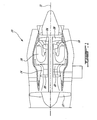
Fig. 1 illustrates agas turbine engine 10 of a type preferably provided for use in subsonic flight, generally comprising in serial flow communication afan 12 through which ambient air is propelled, amultistage compressor 14 for pressurizing the air, acombustor 16 in which the compressed air is mixed with fuel and ignited for generating an annular stream of hot combustion gases, and aturbine section 18 for extracting energy from the combustion gases. - Fuel is injected into the
combustor 16 of thegas turbine engine 10 for mixing with the compressed air from thecompressor 14 and ignition of the resultant mixture. Thefan 12,compressor 14,combustor 16, andturbine 18 are preferably all concentric about a common centrallongitudinal axis 11 of thegas turbine engine 10. - More particularly, in this example, the
multi-stage compressor 14 includes a low-pressure compressor 20 and a high-pressure compressor 22, whereas themultistage turbine 18 includes a high-pressure turbine 24 and a low-pressure turbine 26. The low-pressure compressor 20 is connected to the low-pressure turbine 26 and thehigh pressure compressor 22 is connected to the high-pressure turbine 24. In the gas turbine engine illustrated inFig. 1 , the low-pressure compressor 20 is of the axial compressor type, whereas the high-pressure compressor 22 is of the centrifugal type. -
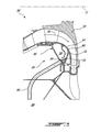
Fig. 2 illustrates aparticle separator 28 for such agas turbine engine 10. More particularly,Fig. 2 partially shows acompressor 30 of the centrifugal type and which has animpeller 32 with aprimary gas path 34. Theimpeller 32 is surrounded by acompressor case 36 which at least partially defines acavity 38, generally shaped as a toroid, therein. Thecavity 38 surrounds thegas path 34. Thecompressor case 36 has acompressor shroud portion 40 adjacent theimpeller 32, and includes a plurality of circumferentially interspaced bleed apertures 42 (only one is shown inFig. 2 ). Thebleed apertures 42 allow gas flow communication between theprimary gas path 34 and thecavity 38, and thereby allow extracting a secondary bleed flow ofair 44, which can be used elsewhere in the engine. - During operation of the engine, particles such as sand, dirt or the like which are ingested into the engine can be transferred into the
cavity 38 through thebleed apertures 42. In this example, thebleed apertures 42 are configured (such as in size, shape, orientation and/or location) to allow a substantial tangential velocity component of the air from theprimary gas path 34 to flow into thecavity 38. Thecavity 38 being circumferential to theimpeller 32, a swirl movement of air, or circular motion of air (around the main axis 11), can be imparted inside thecavity 38 and maintained by the kinetic energy of the tangential velocity component allowed therein. The circular movement of air is used to centrifuge particles which enter thecavity 38 through thebleed apertures 42 radially outwardly, and to convey the particles circumferentially around inside thecompressor case 36. - The
particle separator 28 allows bleed air having a significant tangential velocity component to flow into thecavity 38 formed within the compressor case, and is used, in combination with case geometry, to centrifuge the particles radially outwardly and convey the particles circumferentially, away from a clean air outlet, but towards a particle outlet where the particles can be collected and evacuated. - More particularly, in this example, the
cavity 38 funnels radially-outwardly to a narrowcircumferential tip 46. The narrowcircumferential tip 46 acts as achannel 48 for the particles as they are circumferentially conveyed around thecavity 38. Aclean air outlet 50 of thecavity 38 is provided at a radial position recessed inwardly from thechannel 48, such that clean air (i.e. air from which particles have been separated and removed) can be extracted from theparticle separator 28 for use elsewhere in the engine. Theclean air outlet 50 has a re-entrant edge. Anannular baffle plate 52 extends radially outwardly into thecavity 38 from a location adjacent thebleed apertures 42 on thecompressor shroud portion 40 of thecompressor case 36, toward the narrowcircumferential tip 46 of thecavity 38, and contributes to guide particles ingested through thebleed apertures 42 toward thechannel 48. The baffle can also prevent particles from passing directly from thebleed apertures 42 to theclean air outlet 50 by forcing airflow around the baffle, to a radiallyoutward portion 48 of thecavity 38. - Turning to
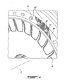
Fig. 3 , as the particles are conveyed circumferentially about thechannel 48 formed by the narrowcircumferential tip 46, they eventually reach aparticle outlet 54 provided therein. In this example, theparticle outlet 54 is provided through a lower portion of thecompressor case 36, more particularly at the circumferential bottom thereof, and theparticle outlet 54 is provided in combination with a particle scoop, or catch, 56 which is tangentially oriented toward the incoming flow of particles, which thereby impinge thereon, and are subsequently guided into theparticle outlet 54. In this example, atubular channel 58 connects theparticle outlet 54 to the atmosphere 60, where the particles can be evacuated. In this example, a portion of the air is evacuated with the particles through theparticle outlet 54. This portion of lost bleed air is however small relative to the amount of air extracted from the clean air outlet 50 (Fig. 2 ). - One way to allow a satisfactory amount of a tangential velocity component of the air flowing through the
bleed apertures 42, is to slant or angle thebleed apertures 42 in the case relative to the longitudinal direction.Fig. 4 illustrates an example of slantedbleed apertures 42 in greater detail, wherein each of thebleed apertures 42 defines anaperture axis 41 that is angled in thecasing 40 relative to thelongitudinal axis 11 of theengine 10 and thereof of theimpeller 32. In one possible embodiment, thebleed apertures 42 in thecasing 40 are tangentially slanted/angled relative to thelongitudinal axis 11. - Hence, in use, airflow from the impeller gas path having a significant tangential velocity component is allowed to flow into the annular cavity surrounding the impeller gas path, via a plurality of circumferentially interspaced apertures. The tangential velocity of the bleed air allowed into the cavity imparts and maintains a circumferential flow of air in the toroidal shaped cavity, which centrifuges particles ingested therein outward towards a radially inwardly facing channel surrounding the cavity, and about which the particles are conveyed by the air movement to an extraction point, where the separated particles are extracted from the rest of the bleed air flow. The particles can thus be substantially separated from the secondary flow of air, such that this secondary air flow is substantially free from particles and can then be extracted from the cavity and re-directed for use elsewhere in the engine.
- It will be understood that the example given above and illustrated is provided for illustrative purposes only. Alternate embodiments of the invention, or variants thereof, can depart from this example. For instance, instead of being applied to a centrifugal compressor, the particle separator can be applied to an axial compressor, although an axial compressor may have a lesser tangential velocity component than a centrifugal compressor, and that this may adversely affect separation efficiency. Also, more than one clean air outlet, or particle outlet, can be used in alternate embodiments. Although the clean air outlet was in the upper portion of the compressor case and the particle outlet was in the bottom of the compressor case in the example above, clean air outlets or particle outlets can alternately be provided at other angular positions. The annular baffle is optional but can help increasing separation efficiency, and its exact configuration can be modified as required in alternate embodiments. Variants to the shape, configuration, and relative position of the bleed apertures illustrated herein can be used in alternate embodiments. Further, in alternate embodiments, variants to the generally inverted "V" shape of the radially outwardly funnelling cavity can be used.
- For many applications, a separation efficiency above 95% will be judged satisfactory. A separation efficiency of above 90% or above 70% can also be satisfactory for some applications. Nonetheless, even a separation efficiency lower than 70% can be satisfactory for some applications.
- Those skilled in the art will therefore appreciate that the forgoing description is illustrative only, and that various other alternatives and modifications can be devised without departing from the scope of the present invention as defined by the appended claims. Accordingly, the present is intended to embrace all such alternatives, modifications and variances which fall within the scope of the appended claims.
Claims (15)
- A particle separator (28) for a gas turbine engine (10), comprising a generally toroidal cavity (38) defined within a casing (36) surrounding a compressor impeller gas path (34) and being in gas flow communication therewith through a plurality of circumferentially interspaced bleed apertures (42) formed in said casing (36), the cavity (38) being funnel-shaped such as to define a radially outer narrow tip (46) circumferentially extending about the cavity (38), at least one clean air outlet (50) being disposed in communication with the cavity (38) and located radially inwardly from the radially outer narrow tip (46) thereof, and a particle outlet (54) radially located at the narrow tip (46), the bleed apertures (42) allowing bleed air from the compressor impeller gas path (34) to flow into the cavity (38), during operation of the gas turbine engine, with a tangential velocity component sufficient to at least partially centrifuge particles present within the bleed air into the radially outer narrow tip (46) of said cavity (38) and convey the particles circumferentially thereabout to the particle outlet (54), wherein air flowing out from the clean air outlet (50) is thereby substantially free of, or has fewer, particles.
- The particle separator of claim 1 wherein the bleed apertures (42) are tangentially oriented within the casing.
- The particle separator of claim 1 or 2 further comprising an annular baffle (52) extending radially outwardly into the cavity (38), the annular baffle (52) being longitudinally adjacent the bleed apertures (42) and disposed between the bleed apertures (42) the clean air outlet (50).
- The particle separator of any preceding claim wherein the particle outlet (50) is positioned in a circumferential lower portion of the narrow tip (46) of the cavity (38).
- The particle separator of any preceding claim wherein a tangentially facing scoop (56) is disposed within the cavity (38) proximate the particle outlet (50) and oriented to receive incoming particles such as to guide incoming particles through the particle outlet (50).
- A gas turbine engine (10) having a compressor rotor (22) rotatable about a main longitudinal axis (11) of the engine (10) and housed in a compressor case (36), the compressor case (36) at least partially defined therewithin a toroidal internal cavity (38) surrounding a gas path (34) of the compressor (34), the compressor case (36) having a plurality of circumferentially interspaced bleed apertures (42) therein which provide gas flow communication between the gas path (34) and the cavity (38), the compressor case (36) having an air outlet (50) in gas flow communication for extracting clean air therefrom, wherein the cavity (38) funnels radially outward to a circumferentially extending narrow tip (46) and the bleed apertures (42) are oriented at a tangentially extending angle relative to said main longitudinal axis (11) to allow a tangential velocity component of the bleed air entering the cavity (38) via said apertures (42) during operation of the gas turbine engine (10) to centrifuge particles present in the bleed air radially outward towards the circumferentially extending narrow tip (46) of the cavity (38) and to convey the particles circumferentially thereabout to a particle outlet (50), the air outlet (50) being positioned radially inwardly from the narrow tip (46) of the cavity (38).
- The gas turbine engine of claim 6, further comprising an annular baffle plate (52) connected to a compressor shroud portion of the compressor case (36) adjacent the bleed apertures (42), the baffle plate (32) extending radially outwardly from the compressor shroud portion toward the narrow tip (46) of the cavity (38), between the bleed apertures (42) and the air outlet (50).
- The gas turbine engine of claim 6 or 7, wherein the air outlet (50) is positioned in an upper portion of the compressor case (36).
- The gas turbine engine of claim 6, 7 or 8, wherein the particle outlet (54) is positioned in a circumferential bottom portion of the compressor case (36).
- The gas turbine engine of any of claims 6 to 9, further comprising a catch plate (56) connected to the compressor case (36) in the narrow radially-outward tip (46) of the cavity (38), adjacent the particle outlet (54) and angled with respect to the tangential velocity component of the bleed air, to guide the centrifuged particles into the particle outlet (54).
- The gas turbine engine of any of claims 6 to 10, wherein the compressor is a centrifugal compressor and the rotor (22) is an impeller.
- A method of separating particles from air during operation of a gas turbine engine (10), the method comprising:extracting bleed air from a compressor gas path (34) into a generally toroidal cavity (38) surrounding the gas path via a plurality of circumferentially interspaced apertures (42) oriented such as to maximize a tangential velocity of the bleed air in said cavity (38);centrifuging particles radially outwardly into a channel (48) formed in the cavity (38) using the tangential velocity of the bleed air flowing within said cavity (38), and maintaining a circumferential flow of the bleed air in the cavity to circumferentially convey the particles about the channel to a particle exit (54);extracting the particles from within the channel (48) of the cavity (38) via the particle exit (54); andextracting clear air from the cavity (38) via a clean air exit (50), the clean air being substantially free from,or has fewer, particles.
- The method of claim 12, further comprising preventing the bleed air from passing directly from the inlet apertures (42) to the clean air outlet (50) of the cavity (38) without first being circumferentially redirected.
- The method of claim 12 or 13, wherein the step of extracting the particles includes evacuating a quantity of the bleed air with the particles.
- The method of any of claims 12 to 14, wherein the step of extracting the clean air includes extracting the clean air from a location within the cavity (38) that is recessed radially inwardly from the channel (48).
Applications Claiming Priority (1)
| Application Number | Priority Date | Filing Date | Title |
|---|---|---|---|
| US12/259,602 US8092145B2 (en) | 2008-10-28 | 2008-10-28 | Particle separator and separating method for gas turbine engine |
Publications (3)
| Publication Number | Publication Date |
|---|---|
| EP2182178A2 true EP2182178A2 (en) | 2010-05-05 |
| EP2182178A3 EP2182178A3 (en) | 2013-05-01 |
| EP2182178B1 EP2182178B1 (en) | 2016-03-16 |
Family
ID=40578209
Family Applications (1)
| Application Number | Title | Priority Date | Filing Date |
|---|---|---|---|
| EP09250762.3A Expired - Fee Related EP2182178B1 (en) | 2008-10-28 | 2009-03-19 | Gas turbine comprising a particle separator and method of separating particles from air during operation of a gas turbine engine |
Country Status (3)
| Country | Link |
|---|---|
| US (1) | US8092145B2 (en) |
| EP (1) | EP2182178B1 (en) |
| CA (1) | CA2671718C (en) |
Cited By (3)
| Publication number | Priority date | Publication date | Assignee | Title |
|---|---|---|---|---|
| EP2299092A3 (en) * | 2009-09-02 | 2014-10-29 | United Technologies Corporation | Air Particle Separator for a Gas Turbine Engine |
| EP3040521A1 (en) * | 2014-12-31 | 2016-07-06 | General Electric Company | Dirt extraction apparatus for a gas turbine engine |
| WO2018017459A1 (en) * | 2016-07-20 | 2018-01-25 | General Electric Company | High pressure cyclonic separator for turbomachinery |
Families Citing this family (36)
| Publication number | Priority date | Publication date | Assignee | Title |
|---|---|---|---|---|
| US10286407B2 (en) | 2007-11-29 | 2019-05-14 | General Electric Company | Inertial separator |
| US20100172753A1 (en) * | 2009-01-08 | 2010-07-08 | Frank Lin | Compressor side inlet with improved aerodynamic performance and reduced manufacturing complexity |
| US8945254B2 (en) | 2011-12-21 | 2015-02-03 | General Electric Company | Gas turbine engine particle separator |
| US8926268B2 (en) * | 2012-03-08 | 2015-01-06 | Hamilton Sundstrand Corporation | Bleed noise reduction |
| US9067163B2 (en) | 2013-04-26 | 2015-06-30 | Hamilton Sundstrand Corporation | Particle separator |
| US9272293B2 (en) | 2013-04-29 | 2016-03-01 | Hamilton Sundstrand Corporation | Particle separator |
| CA2859441C (en) | 2013-08-16 | 2021-10-12 | Eric Loth | Particle separator |
| US9650916B2 (en) | 2014-04-09 | 2017-05-16 | Honeywell International Inc. | Turbomachine cooling systems |
| WO2016032585A2 (en) | 2014-05-29 | 2016-03-03 | General Electric Company | Turbine engine, components, and methods of cooling same |
| US11033845B2 (en) | 2014-05-29 | 2021-06-15 | General Electric Company | Turbine engine and particle separators therefore |
| US9915176B2 (en) | 2014-05-29 | 2018-03-13 | General Electric Company | Shroud assembly for turbine engine |
| CA2949547A1 (en) | 2014-05-29 | 2016-02-18 | General Electric Company | Turbine engine and particle separators therefore |
| US10036319B2 (en) | 2014-10-31 | 2018-07-31 | General Electric Company | Separator assembly for a gas turbine engine |
| US10167725B2 (en) * | 2014-10-31 | 2019-01-01 | General Electric Company | Engine component for a turbine engine |
| US10012147B2 (en) | 2015-08-17 | 2018-07-03 | United Technologies Corporation | Apparatus and method for air particle separator in gas turbine engine |
| US10287992B2 (en) | 2015-08-26 | 2019-05-14 | General Electric Company | Gas turbine engine hybrid variable bleed valve |
| US10835848B2 (en) | 2015-09-21 | 2020-11-17 | Raytheon Technologies Corporation | Apparatus and method for air particle capture in a gas turbine engine |
| US10202903B2 (en) | 2015-09-22 | 2019-02-12 | United Technologies Corporation | Apparatus and method for air particle separation in a gas turbine engine |
| US10174620B2 (en) | 2015-10-15 | 2019-01-08 | General Electric Company | Turbine blade |
| US10428664B2 (en) | 2015-10-15 | 2019-10-01 | General Electric Company | Nozzle for a gas turbine engine |
| US9988936B2 (en) | 2015-10-15 | 2018-06-05 | General Electric Company | Shroud assembly for a gas turbine engine |
| US10196982B2 (en) | 2015-11-04 | 2019-02-05 | General Electric Company | Gas turbine engine having a flow control surface with a cooling conduit |
| US10724436B2 (en) | 2016-01-21 | 2020-07-28 | General Electric Company | Inlet particle separator for a turbine engine |
| US10227930B2 (en) | 2016-03-28 | 2019-03-12 | General Electric Company | Compressor bleed systems in turbomachines and methods of extracting compressor airflow |
| US10208628B2 (en) * | 2016-03-30 | 2019-02-19 | Honeywell International Inc. | Turbine engine designs for improved fine particle separation efficiency |
| US10400670B2 (en) | 2016-06-15 | 2019-09-03 | General Electric Company | Inlet particle separator for a turbine engine |
| US10704425B2 (en) | 2016-07-14 | 2020-07-07 | General Electric Company | Assembly for a gas turbine engine |
| US10830138B2 (en) * | 2016-07-20 | 2020-11-10 | General Electric Company | Fine debris multi-stage separation system |
| US10695704B2 (en) * | 2016-07-20 | 2020-06-30 | General Electric Company | Multi-station debris separation system |
| US10393021B2 (en) * | 2016-09-01 | 2019-08-27 | Rolls-Royce North American Technologies Inc. | Particle separator |
| US20180135516A1 (en) * | 2016-11-16 | 2018-05-17 | Honeywell International Inc. | Scavenge methodologies for turbine engine particle separation concepts |
| US10738699B2 (en) | 2018-01-19 | 2020-08-11 | Rolls-Royce North American Technologies Inc. | Air-inlet particle separator having a bleed surface |
| US11035257B2 (en) | 2018-01-23 | 2021-06-15 | Honeywell International Inc. | Driven cavity particle separator |
| US10816014B2 (en) | 2018-07-25 | 2020-10-27 | Honeywell International Inc. | Systems and methods for turbine engine particle separation |
| US11371434B2 (en) | 2020-08-19 | 2022-06-28 | Honeywell International Inc. | Compressor particle separator for gas turbine engine |
| US11421709B2 (en) * | 2020-09-08 | 2022-08-23 | Honeywell International Inc. | Systems for interstage particle separation in multistage radial compressors of turbine engines |
Citations (7)
| Publication number | Priority date | Publication date | Assignee | Title |
|---|---|---|---|---|
| DE1026916B (en) * | 1955-05-06 | 1958-03-27 | Licentia Gmbh | Turbo blower for dusty gases |
| GB1412780A (en) * | 1971-11-23 | 1975-11-05 | Gen Electric | Gas turbine engine air inlet assemblies |
| US4702071A (en) * | 1985-06-28 | 1987-10-27 | Rolls-Royce Plc | Inlet particle separator |
| US4928480A (en) * | 1988-03-04 | 1990-05-29 | General Electric Company | Separator having multiple particle extraction passageways |
| JP2002242699A (en) * | 2001-02-20 | 2002-08-28 | Kawasaki Heavy Ind Ltd | Gas turbine engine provided with foreign material removing structure |
| US20070144139A1 (en) * | 2004-12-06 | 2007-06-28 | Honda Motor Co., Ltd. | Gas turbine engine provided with a foreign matter removal passage |
| US20080152500A1 (en) * | 2006-12-20 | 2008-06-26 | Carsten Mehring | Inertial particle separator for compressor shroud bleed |
Family Cites Families (16)
| Publication number | Priority date | Publication date | Assignee | Title |
|---|---|---|---|---|
| US3673771A (en) * | 1970-11-23 | 1972-07-04 | Avco Corp | Multi-channel particle separator |
| US3751907A (en) * | 1971-12-08 | 1973-08-14 | Caterpillar Tractor Co | Inertial air cleaner for gas turbine |
| US3993463A (en) * | 1975-08-28 | 1976-11-23 | The United States Of America As Represented By The Secretary Of The Army | Particle separator for turbine engines of aircraft |
| US4304094A (en) * | 1979-11-16 | 1981-12-08 | United Technologies Corp. | Engine air particle separator for use with gas turbine engine |
| US4798047A (en) * | 1983-12-19 | 1989-01-17 | Elliott Turbomachinery Co., Inc. | Particulate collection and cooling in a turbomachine |
| GB2203801B (en) * | 1987-04-14 | 1991-11-27 | Rolls Royce Plc | A gas turbine engine |
| US5431535C1 (en) * | 1989-12-05 | 2001-01-09 | Boeing Co | Foreign matter diverter systems for turbofan engines |
| US5253472A (en) * | 1990-02-28 | 1993-10-19 | Dev Sudarshan P | Small gas turbine having enhanced fuel economy |
| DE4326799A1 (en) * | 1993-08-10 | 1995-02-16 | Abb Management Ag | Device for extracting secondary air from an axial compressor |
| US5586859A (en) * | 1995-05-31 | 1996-12-24 | United Technologies Corporation | Flow aligned plenum endwall treatment for compressor blades |
| US5558496A (en) * | 1995-08-21 | 1996-09-24 | General Electric Company | Removing particles from gas turbine coolant |
| JP2003517525A (en) * | 1998-02-26 | 2003-05-27 | アリソン・アドバンスト・ディベロップメント・カンパニー | Compressor end wall bleed system |
| JP4358965B2 (en) * | 2000-03-27 | 2009-11-04 | 株式会社日立産機システム | Centrifugal impeller and air purifier |
| ITMI20021218A1 (en) * | 2002-06-05 | 2003-12-05 | Nuovo Pignone Spa | PROCESS GAS EXTRACTION DEVICE FOR AN AXIAL COMPRESSOR WITH GOOD ADAPTABILITY TO A CHANGE OF OPERATING SPECIFICATIONS |
| DE10330471A1 (en) * | 2003-07-05 | 2005-02-03 | Alstom Technology Ltd | Device for separating foreign particles from the cooling air that can be fed to the moving blades of a turbine |
| US7284953B2 (en) * | 2005-08-29 | 2007-10-23 | United Technologies Corporation | Dirt separator for gas turbine air supply |
-
2008
- 2008-10-28 US US12/259,602 patent/US8092145B2/en active Active
-
2009
- 2009-03-19 EP EP09250762.3A patent/EP2182178B1/en not_active Expired - Fee Related
- 2009-07-14 CA CA2671718A patent/CA2671718C/en not_active Expired - Fee Related
Patent Citations (7)
| Publication number | Priority date | Publication date | Assignee | Title |
|---|---|---|---|---|
| DE1026916B (en) * | 1955-05-06 | 1958-03-27 | Licentia Gmbh | Turbo blower for dusty gases |
| GB1412780A (en) * | 1971-11-23 | 1975-11-05 | Gen Electric | Gas turbine engine air inlet assemblies |
| US4702071A (en) * | 1985-06-28 | 1987-10-27 | Rolls-Royce Plc | Inlet particle separator |
| US4928480A (en) * | 1988-03-04 | 1990-05-29 | General Electric Company | Separator having multiple particle extraction passageways |
| JP2002242699A (en) * | 2001-02-20 | 2002-08-28 | Kawasaki Heavy Ind Ltd | Gas turbine engine provided with foreign material removing structure |
| US20070144139A1 (en) * | 2004-12-06 | 2007-06-28 | Honda Motor Co., Ltd. | Gas turbine engine provided with a foreign matter removal passage |
| US20080152500A1 (en) * | 2006-12-20 | 2008-06-26 | Carsten Mehring | Inertial particle separator for compressor shroud bleed |
Cited By (3)
| Publication number | Priority date | Publication date | Assignee | Title |
|---|---|---|---|---|
| EP2299092A3 (en) * | 2009-09-02 | 2014-10-29 | United Technologies Corporation | Air Particle Separator for a Gas Turbine Engine |
| EP3040521A1 (en) * | 2014-12-31 | 2016-07-06 | General Electric Company | Dirt extraction apparatus for a gas turbine engine |
| WO2018017459A1 (en) * | 2016-07-20 | 2018-01-25 | General Electric Company | High pressure cyclonic separator for turbomachinery |
Also Published As
| Publication number | Publication date |
|---|---|
| EP2182178B1 (en) | 2016-03-16 |
| US8092145B2 (en) | 2012-01-10 |
| CA2671718A1 (en) | 2010-04-28 |
| EP2182178A3 (en) | 2013-05-01 |
| US20100104422A1 (en) | 2010-04-29 |
| CA2671718C (en) | 2011-07-26 |
Similar Documents
| Publication | Publication Date | Title |
|---|---|---|
| CA2671718C (en) | Particle separator and separating method for gas turbine engine | |
| US10450951B2 (en) | Cyclonic separator for a turbine engine | |
| US10975731B2 (en) | Turbine engine, components, and methods of cooling same | |
| US11541340B2 (en) | Inducer assembly for a turbine engine | |
| US10167725B2 (en) | Engine component for a turbine engine | |
| EP3196442B1 (en) | Inlet particle separator for a turbine engine | |
| US10286407B2 (en) | Inertial separator | |
| US9915176B2 (en) | Shroud assembly for turbine engine | |
| US20140290254A1 (en) | Cyclonic Dirt Separating Turbine Accelerator | |
| EP3225818A1 (en) | Turbine engine designs for improved fine particle separation efficiency | |
| US10400670B2 (en) | Inlet particle separator for a turbine engine | |
| US11199111B2 (en) | Assembly for particle removal | |
| US11918943B2 (en) | Inducer assembly for a turbine engine | |
| EP3599344A1 (en) | Systems for turbine engine particle separation |
Legal Events
| Date | Code | Title | Description |
|---|---|---|---|
| PUAI | Public reference made under article 153(3) epc to a published international application that has entered the european phase |
Free format text: ORIGINAL CODE: 0009012 |
|
| AK | Designated contracting states |
Kind code of ref document: A2 Designated state(s): AT BE BG CH CY CZ DE DK EE ES FI FR GB GR HR HU IE IS IT LI LT LU LV MC MK MT NL NO PL PT RO SE SI SK TR |
|
| AX | Request for extension of the european patent |
Extension state: AL BA RS |
|
| PUAL | Search report despatched |
Free format text: ORIGINAL CODE: 0009013 |
|
| AK | Designated contracting states |
Kind code of ref document: A3 Designated state(s): AT BE BG CH CY CZ DE DK EE ES FI FR GB GR HR HU IE IS IT LI LT LU LV MC MK MT NL NO PL PT RO SE SI SK TR |
|
| AX | Request for extension of the european patent |
Extension state: AL BA RS |
|
| RIC1 | Information provided on ipc code assigned before grant |
Ipc: F01D 25/32 20060101AFI20130322BHEP Ipc: F02C 6/08 20060101ALI20130322BHEP Ipc: F02C 7/052 20060101ALI20130322BHEP |
|
| 17P | Request for examination filed |
Effective date: 20131101 |
|
| RBV | Designated contracting states (corrected) |
Designated state(s): AT BE BG CH CY CZ DE DK EE ES FI FR GB GR HR HU IE IS IT LI LT LU LV MC MK MT NL NO PL PT RO SE SI SK TR |
|
| AKX | Designation fees paid |
Designated state(s): DE FR GB |
|
| GRAP | Despatch of communication of intention to grant a patent |
Free format text: ORIGINAL CODE: EPIDOSNIGR1 |
|
| INTG | Intention to grant announced |
Effective date: 20150902 |
|
| GRAS | Grant fee paid |
Free format text: ORIGINAL CODE: EPIDOSNIGR3 |
|
| GRAA | (expected) grant |
Free format text: ORIGINAL CODE: 0009210 |
|
| AK | Designated contracting states |
Kind code of ref document: B1 Designated state(s): DE FR GB |
|
| REG | Reference to a national code |
Ref country code: GB Ref legal event code: FG4D |
|
| REG | Reference to a national code |
Ref country code: DE Ref legal event code: R096 Ref document number: 602009036791 Country of ref document: DE |
|
| REG | Reference to a national code |
Ref country code: FR Ref legal event code: PLFP Year of fee payment: 8 |
|
| REG | Reference to a national code |
Ref country code: DE Ref legal event code: R097 Ref document number: 602009036791 Country of ref document: DE |
|
| PLBE | No opposition filed within time limit |
Free format text: ORIGINAL CODE: 0009261 |
|
| STAA | Information on the status of an ep patent application or granted ep patent |
Free format text: STATUS: NO OPPOSITION FILED WITHIN TIME LIMIT |
|
| REG | Reference to a national code |
Ref country code: FR Ref legal event code: PLFP Year of fee payment: 9 |
|
| 26N | No opposition filed |
Effective date: 20161219 |
|
| REG | Reference to a national code |
Ref country code: DE Ref legal event code: R082 Ref document number: 602009036791 Country of ref document: DE Representative=s name: SCHMITT-NILSON SCHRAUD WAIBEL WOHLFROM PATENTA, DE |
|
| REG | Reference to a national code |
Ref country code: FR Ref legal event code: PLFP Year of fee payment: 10 |
|
| PGFP | Annual fee paid to national office [announced via postgrant information from national office to epo] |
Ref country code: DE Payment date: 20190219 Year of fee payment: 11 Ref country code: GB Payment date: 20190222 Year of fee payment: 11 |
|
| PGFP | Annual fee paid to national office [announced via postgrant information from national office to epo] |
Ref country code: FR Payment date: 20190220 Year of fee payment: 11 |
|
| REG | Reference to a national code |
Ref country code: DE Ref legal event code: R119 Ref document number: 602009036791 Country of ref document: DE |
|
| PG25 | Lapsed in a contracting state [announced via postgrant information from national office to epo] |
Ref country code: DE Free format text: LAPSE BECAUSE OF NON-PAYMENT OF DUE FEES Effective date: 20201001 Ref country code: FR Free format text: LAPSE BECAUSE OF NON-PAYMENT OF DUE FEES Effective date: 20200331 |
|
| GBPC | Gb: european patent ceased through non-payment of renewal fee |
Effective date: 20200319 |
|
| PG25 | Lapsed in a contracting state [announced via postgrant information from national office to epo] |
Ref country code: GB Free format text: LAPSE BECAUSE OF NON-PAYMENT OF DUE FEES Effective date: 20200319 |