EP2182165A2 - Drilling apparatus and method - Google Patents
Drilling apparatus and method Download PDFInfo
- Publication number
- EP2182165A2 EP2182165A2 EP09275034A EP09275034A EP2182165A2 EP 2182165 A2 EP2182165 A2 EP 2182165A2 EP 09275034 A EP09275034 A EP 09275034A EP 09275034 A EP09275034 A EP 09275034A EP 2182165 A2 EP2182165 A2 EP 2182165A2
- Authority
- EP
- European Patent Office
- Prior art keywords
- assembly
- orientation
- lower assembly
- control device
- reactive torque
- Prior art date
- Legal status (The legal status is an assumption and is not a legal conclusion. Google has not performed a legal analysis and makes no representation as to the accuracy of the status listed.)
- Granted
Links
Images




Classifications
-
- E—FIXED CONSTRUCTIONS
- E21—EARTH OR ROCK DRILLING; MINING
- E21B—EARTH OR ROCK DRILLING; OBTAINING OIL, GAS, WATER, SOLUBLE OR MELTABLE MATERIALS OR A SLURRY OF MINERALS FROM WELLS
- E21B7/00—Special methods or apparatus for drilling
- E21B7/04—Directional drilling
- E21B7/06—Deflecting the direction of boreholes
- E21B7/067—Deflecting the direction of boreholes with means for locking sections of a pipe or of a guide for a shaft in angular relation, e.g. adjustable bent sub
-
- E—FIXED CONSTRUCTIONS
- E21—EARTH OR ROCK DRILLING; MINING
- E21B—EARTH OR ROCK DRILLING; OBTAINING OIL, GAS, WATER, SOLUBLE OR MELTABLE MATERIALS OR A SLURRY OF MINERALS FROM WELLS
- E21B47/00—Survey of boreholes or wells
- E21B47/02—Determining slope or direction
- E21B47/024—Determining slope or direction of devices in the borehole
Definitions
- An apparatus and a method for use in drilling a borehole An apparatus and a method for use in drilling a borehole.
- Drilling of subterranean boreholes is often performed by rotating a drill bit which is located at a distal end of a drilling string.
- the drill bit may be rotated by rotating the entire drill string from a surface location and/or by using a rotary drilling motor which is connected with the drilling string and which is located adjacent to the drill bit.
- the drilling string may be made up of individual joints of drilling pipe which are connected together to form the drilling string.
- the drilling string may be made up of a continuous length of coiled tubing which is stored on a large spool.
- the entire drill string may be rotated with relative ease using a rotary table or a top drive on the drilling rig.
- the drilling string is made up of a continuous length of coiled tubing, it is relatively more difficult to rotate the entire drill string because the spool must also be rotated.
- Drilling while rotating the drill bit only by rotating the entire drilling string is often referred to as "rotary drilling”. Drilling while rotating the drill bit only with a rotary drilling motor is often referred to as “sliding drilling”. Drilling while rotating the drill bit both by rotating the entire drilling string and with a rotary drilling motor is often referred to as "performance drilling”.
- Directional drilling involves "steering" the drill bit so that the drill bit drills along a desired path.
- Directional drilling therefore requires a mechanism for orienting the drill bit so that it drills along the desired path.
- the orientation of the drill bit during directional drilling is often referred to as a "toolface orientation”.
- Directional drilling may be performed using a bend in the drilling string or using a steering tool which is associated with the drilling string.
- the orientation of the bend must be controlled in order to provide a desired toolface orientation.
- steering with a bend in the drilling string may typically only be achieved during sliding drilling, since rotary drilling will result in a constant rotation of the bend and constant variation of the toolface orientation.
- a desired toolface orientation may be achieved either by controlling the actuation of the steering tool or by maintaining the steering device at a fixed actuation and controlling the orientation of the steering tool in a similar manner as performing directional drilling with a bend in the drilling string.
- the toolface orientation may change in an undesired manner during drilling due to forces applied to the drill bit and the drilling string.
- forces may be forces applied to the drill string from the surface location or may be reactive forces exerted on the drill bit and/or the drilling string by the borehole.
- Reactive torque results from a reaction of the borehole to rotation of the drill bit against the distal end of the borehole. Reactive torque tends to rotate the drill bit in a direction opposite to that which is imposed upon the drill bit by rotation of the drill string and/or by a rotary drilling motor. Reactive torque may cause changes in the toolface orientation and also imposes potentially damaging stresses on the drilling string.
- U.S. Patent No. 5,485,889 describes a drilling system and method for use with coiled tubing.
- the drilling system includes a control device.
- the control device includes a downstream section which is connected to a drilling tool having a bend axis, an upstream section which is connected to coiled tubing, and a swivel coupling assembly which connects the downstream section and the upstream section.
- a pump and a circuit are associated with the downstream section, the upstream section and the swivel coupling assembly so that relative rotation between the downstream section and the upstream section causes the pump to pump fluid through the circuit.
- a flow restricting orifice and a valve are provided in the circuit.
- the control device may be actuated to form a straight section of a borehole and a curved section of the borehole.
- the control device In order to form the straight section of the borehole, the control device is actuated to permit relative rotation of the downstream section and the upstream section at a rate which is less than the rate of rotation of the drill bit.
- the control device In order to form the curved section of the borehole, the control device is actuated to prevent relative rotation of the downstream section and the upstream section, thereby facilitating orientation of the bend axis of the drilling tool.
- Actuation of the control device to prevent relative rotation of the downstream section and the upstream section is achieved by actuating the valve to a closed position so that circulation of fluid through the circuit is prevented.
- the valve is actuated from the surface location through a control cable which extends to the surface location.
- a sensor communicates through the control cable with the surface location in order to communicate unspecified information to the surface location.
- U.S. Patent No. 6,059,050 (Gray ) describes an apparatus for controlling relative rotation of a drilling tool due to reactive torque.
- the apparatus includes a first member and a second member which are relatively rotatable and a hydraulic pump having a first pump part mounted on the first member and a second pump part mounted on the second member.
- the pump is arranged such that relative rotation of the first and second members causes relative rotation of the first and second pump parts, which results in pumping of hydraulic fluid from a first chamber to a second chamber within which the hydraulic fluid is under pressure.
- a brake having a first brake part on the first member and a second brake part on the second member is associated with the second chamber such that the brake is actuated by the hydraulic pressure in the second chamber.
- a duct and a variable orifice control the flow of fluid from the second chamber back to the first chamber, thereby controlling the braking force exerted by the brake and the relative rotation of the first and second members.
- the apparatus may be actuated to permit or prevent relative rotation of the first and second members. Actuation of the apparatus to prevent relative rotation of the first and second members is achieved by actuating the variable orifice to a closed position so that the flow of fluid from the second chamber back to the first chamber is prevented.
- the variable orifice is controlled by an electrical control line from a suitable control system.
- a sensor communicates through the control cable with the surface location in order to communicate unspecified information to the surface location.
- U.S. Patent No. 6,571,888 (Comeau et al ) describes an apparatus and a method for directional drilling with coiled tubing.
- the apparatus includes an uphole sub connected to coiled tubing, a downhole sub having a bent housing, a drill bit and a first motor for rotating the drill bit, a rotary connection between the uphole sub and the downhole sub for enabling rotation therebetween, and a clutch positioned between the rotary connection and the uphole sub.
- the clutch is operable between engaged and disengaged positions using fluid cycles applied alternately to engage and disengage the clutch. In the engaged position of the clutch, the downhole sub is rotatable relative to the uphole sub.
- the apparatus may be further comprised of a speed reducer for dissipating the reactive torque tending to rotate the downhole sub when the clutch is in the engaged position.
- U.S. Patent Application Publication No. US 2003/0056963 A1 (Wenzel ) describes an apparatus for controlling a downhole drilling motor assembly which includes a tubular housing, a mandrel rotatably mounted within the housing, and an hydraulic damper assembly disposed between the housing and the mandrel.
- the hydraulic damper assembly limits the rate of rotation of the mandrel within the housing in order to provide a preset resistance to reactive torque.
- the hydraulic damper assembly includes an annular body which is positioned within an annular chamber between the housing and the mandrel.
- the annular body is connected with the mandrel with splines so that the annular body rotates with the mandrel and can reciprocate axially relative to the mandrel.
- a guide track on the exterior surface of the annular body engages with guide members on the housing.
- the guide track has a zig-zag pattern which causes the annular body to reciprocate axially in the annular chamber as the housing rotates relative to the mandrel.
- the annular chamber is filled with hydraulic fluid.
- the annular body is provided with hydraulic valves which provide a restricted flow of the hydraulic fluid through the annular body as the annular body reciprocates within the annular chamber, thereby providing the preset resistance which limits the rate of rotation of the mandrel within the housing.
- the apparatus may be actuated to permit or prevent rotation of the mandrel within the housing.
- Actuation of the apparatus to prevent rotation of the mandrel within the housing may be achieved by actuating an annular plug to block the hydraulic valves, by actuating a clutch between the mandrel and the housing to lock the mandrel and housing together, or by actuating an electric valve to block the movement of hydraulic fluid within the annular chamber.
- apparatus for use in drilling a borehole comprising:
- the feedback control system is typically comprised of a feedback processor for processing the sensed actual orientation of the lower assembly in order to generate a feedback actuation instruction for actuating the reactive torque control device in order to achieve the target orientation of the lower assembly.
- the feedback control system may include a reactive torque control device controller for receiving the feedback actuation instruction and for actuating the reactive torque control device in order to implement the feedback actuation instruction.
- the feedback control system may include a feedback communication link between the orientation sensing device and the feedback processor, for transmitting the sensed actual orientation of the lower assembly from the orientation sensing device to the feedback processor.
- the lower assembly may provide a toolface orientation for facilitating directional drilling.
- the toolface orientation is optionally provided by a bend associated with the lower assembly.
- the orientation sensing device optionally comprises an orientation sensor associated with the lower assembly such that the orientation sensor is a component of the lower assembly.
- the feedback processor is optionally associated with the upper assembly such that the feedback processor is a component of the upper assembly.
- the feedback communication link optionally comprises a wireline between the orientation sensor and the feedback processor.
- the feedback communication link optionally comprises a rotatable signal coupler between the orientation sensor and the feedback processor.
- the rotatable signal coupler typically comprises a slip ring.
- the reactive torque control device typically comprises a pump, which is optionally driven by relative rotation between the lower assembly and the upper assembly.
- the reactive torque control device typically comprises a loop containing a pumping fluid, wherein the relative rotation between the lower assembly and the upper assembly causes the pump to pump the pumping fluid around the loop, wherein the loop comprises a pumping resistance, and wherein the pumping resistance loads the pump and thereby impedes the relative rotation between the lower assembly and the upper assembly.
- the pumping resistance is typically adjustable, and optionally can comprise a flow restrictor positioned in the loop.
- the flow restrictor is adjustable, typically by the reactive torque control device controller.
- the loop may be selectively blocked in order to prevent the pumping fluid from being pumped around the loop by the pump.
- the reactive torque control device typically comprises a valve positioned in the loop and the valve may optionally be actuated between an open position and a closed position in which the loop is blocked in order to prevent the pumping fluid from being pumped around the loop by the pump.
- the valve is optionally actuatable by the reactive torque control device controller.
- the pump is typically a swash plate pump.
- the reactive torque control device typically comprises a brake associated with the loop, wherein the brake is comprised of a first brake part associated with the upper assembly and a second brake part associated with the lower assembly, and wherein the brake is actuated by a fluid pressure in the loop.
- the first brake part and the second brake part are optionally urged into engagement with each other as a result of the fluid pressure in the loop, thereby providing an engagement force between the first brake part and the second brake part which impedes the relative rotation between the lower assembly and the upper assembly, and wherein the engagement force between the first brake part and the second brake part increases as the fluid pressure in the loop increases.
- the pumping resistance is comprised of a first flow restrictor positioned in the loop on an upstream side of the brake and a second flow restrictor positioned in the loop on a downstream side of the brake.
- the reactive torque control device typically comprises a first valve positioned in the loop on an upstream side of the brake and a second valve positioned in the loop on a downstream side of the brake, and typically the first valve and the second valve may each be actuated between an open position and a closed position in which the loop is blocked between the first valve and the second valve in order to maintain the engagement force between the first brake part and the second brake part.
- the loop is comprised of a pressure relief bypass line positioned in the loop for bypassing the first valve and the second valve when the fluid pressure in the loop exceeds a bypass pressure as determined by the pressure relief bypass line.
- the loop typically comprises a dump valve for releasing an amount of the pumping fluid from the loop when the fluid pressure in the loop exceeds a dump pressure as determined by the dump valve.
- the reactive torque control device typically comprises an accumulator in communication with the loop, for supplying additional pumping fluid to the loop when the fluid pressure in the loop is below an accumulator threshold pressure as determined by the accumulator.
- the first valve and the second valve are typically both actuatable by the reactive torque control device controller.
- the orientation sensing device typically comprises an orientation sensor associated with the upper assembly such that the orientation sensor is a component of the upper assembly and such that the orientation sensor provides a sensed actual orientation of the upper assembly.
- the orientation sensing device typically comprises a referencing device for providing a reference orientation between the upper assembly and the lower assembly so that the sensed actual orientation of the lower assembly can be obtained from the sensed actual orientation of the upper assembly.
- the feedback processor is typically associated with the upper assembly such that the feedback processor is a component of the upper assembly.
- the reactive torque control device controller is typically associated with the upper assembly such that the reactive torque control device controller is a component of the upper assembly.
- the feedback control system typically comprises a memory for storing the target orientation of the lower assembly.
- the apparatus includes a surface communication link between a surface location and the feedback control system, for communicating a downlink instruction from the surface location to the feedback control system.
- the surface communication link communicates an uplink communication from the feedback control system to the surface location.
- the surface communication link typically comprises a measurement-while-drilling telemetry system, and may comprise a pressure pulse telemetry system.
- the surface communication link typically comprises a fluid flowrate telemetry system comprising a turbine and a rotation sensor for sensing a rotational speed of the turbine.
- the feedback control system typically comprises a memory for storing the downlink instruction.
- the downlink instruction typically comprises the target orientation of the lower assembly.
- the drilling string typically comprises a section of coiled tubing and the upper assembly is optionally connected with the coiled tubing.
- the upper assembly typically comprises an upper section, a lower section adjacent to the orientable rotatable connection, and a swivel connection between the upper section and the lower section so that the upper section is rotatable relative to the lower section.
- the lower section of the upper assembly typically comprises a rotation restraining device for restraining the lower section of the upper assembly from rotating relative to the borehole.
- the reactive torque control device is typically actuatable between a first position which provides a minimum resistance to rotation of the lower assembly relative to the upper assembly and a second position which provides a maximum resistance to rotation of the lower assembly relative to the upper assembly, wherein rotation of the lower assembly relative to the upper assembly is allowed when the reactive torque control device is actuated to the first position, and wherein rotation of the lower assembly relative to the upper assembly is prevented when the reactive torque control device is actuated to the second position.
- the reactive torque control device is optionally actuatable to at least one intermediate position between the first position and the second position, which intermediate position provides an intermediate resistance to rotation of the lower assembly relative to the upper assembly.
- the reactive torque control device is optionally actuatable to a plurality of intermediate positions between the first position and the second position in order to provide a variable intermediate resistance to rotation of the lower assembly relative to the upper assembly.
- the apparatus can optionally include at least one parameter sensing device, for sensing a parameter other than the actual orientation of the lower assembly and for providing a sensed parameter value relating to the parameter.
- the at least one parameter sensing device can optionally be associated with the feedback control system so that the feedback control system actuates the reactive torque control device in response to the sensed parameter value.
- the invention also provides a method of directional drilling of a borehole using an apparatus comprising an upper assembly connected with a drilling string, a lower assembly comprising a rotary drilling motor such that the lower assembly is subjected to reactive torque during drilling as a result of the operation of the drilling motor, an orientable rotatable connection between the upper assembly and the lower assembly, and a reactive torque control device associated with the orientable rotatable connection, wherein the reactive torque control device is actuatable to selectively allow rotation of the lower assembly relative to the upper assembly or prevent rotation of the lower assembly relative to the upper assembly, the method comprising the following:
- the upper assembly typically comprises an upper section, a lower section adjacent to the orientable rotatable connection, and a swivel connection between the upper section and the lower section so that the upper section is rotatable relative to the lower section, further comprising rotating the upper section of the upper assembly while operating the drilling motor.
- the method may include the additional optional step of restraining the lower section of the upper assembly from rotating relative to the borehole.
- the method may include the additional optional step of communicating a downlink instruction to the apparatus, wherein the downlink instruction is comprised of the target orientation of the lower assembly.
- the method may include the additional optional step of repeating (b) through (f) while the directional drilling is being performed.
- the method may include the additional optional step of communicating a downlink instruction to the apparatus periodically while the directional drilling is being performed, wherein the downlink instruction is comprised of the target orientation of the lower assembly.
- the target orientation of the lower assembly is an updated target orientation of the lower assembly.
- the downlink instruction is comprised of a sequence of target orientations of the lower assembly.
- the sensed actual orientation of the lower assembly is provided by obtaining a sensed actual orientation of the upper assembly and a reference orientation between the upper assembly and the lower assembly.
- the method may include the additional optional step of communicating an uplink communication from the apparatus, wherein the uplink communication is comprised of the sensed actual orientation of the lower assembly.
- the method may include the additional optional step of communicating a downlink instruction to the apparatus, wherein the downlink instruction is comprised of the target orientation of the lower assembly.
- the reactive torque control device is actuatable between a first position which provides a minimum resistance to rotation of the lower assembly relative to the upper assembly and a second position which provides a maximum resistance to rotation of the lower assembly relative to the upper assembly and wherein actuating the reactive torque control device to prevent rotation of the lower assembly relative to the upper assembly is comprised of actuating the reactive torque control device to the second position.
- the reactive torque control device is actuatable to at least one intermediate position between the first position and the second position, which intermediate position provides an intermediate resistance to rotation of the lower assembly relative to the upper assembly, and wherein actuating the reactive torque control device to allow the lower assembly to rotate relative to the upper assembly is comprised of actuating the reactive torque control system to the intermediate position.
- the reactive torque control device is actuatable to a plurality of intermediate positions between the first position and the second position in order to provide a variable intermediate resistance to rotation of the lower assembly relative to the upper assembly, and wherein actuating the reactive torque control device to allow the lower assembly to rotate relative to the upper assembly is comprised of actuating the reactive torque control device to one of the intermediated positions.
- the method of the invention can optionally be performed with steps (b) to (f) being repeated using an updated target orientation of the lower assembly, and including the optional additional step of generating the updated target orientation of the lower assembly.
- the updated target orientation of the lower assembly is typically generated using data from at least one sensing device associated with the apparatus.
- the updated target orientation of the lower assembly is typically generated by the feedback control system.
- the present invention is an apparatus and a method for use in drilling a borehole.
- the invention utilizes reactive torque to control the orientation of one or more components of a drilling string during drilling.
- the invention is particularly useful for controlling a toolface orientation in directional drilling.
- upper means relatively proximal and/or uphole and “lower” means relatively distal and/or downhole with respect to position within a drilling string or location within a borehole, relative to a surface location.
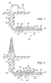
- Figure 1 provides a basic schematic view of one exemplary configuration of equipment which may be used to drill a borehole (10) from a surface location (12), including a schematic depiction of the apparatus (20) of the invention.
- the surface location (12) may be a ground surface, a drilling platform, or any other location outside of the borehole (10) from which drilling is controlled.
- an embodiment of the apparatus (20) of the invention is comprised of an upper assembly (22).
- the upper assembly (22) has an upper end (24) which is connected with a drilling string (26).
- the apparatus is further comprised of a lower assembly (28).
- the lower assembly (28) includes a rotary drilling motor (30).
- the drilling motor (30) includes a drill bit (32) which is positioned at a lower end (34) of the lower assembly (28).
- the drilling string (26) may be comprised of a plurality of relatively short joints of pipe which are connected together, may be comprised of a single continuous length of pipe, or may be comprised of relatively long joints or lengths of pipe which are connected together. As depicted in Figure 1 , the drilling string (26) is comprised of a continuous length of pipe known as coiled tubing (50). As depicted in Figure 2 , the drilling string (26) is comprised of relatively short joints of pipe (51) which are connected together.
- the coiled tubing (50) is stored on a spool (52) which is located at the surface location (12). If the length of a single spool (52) of coiled tubing (50) is not sufficient to complete the drilling operation, lengths of coiled tubing (50) may be connected together to form the drilling string (26).
- drilling is typically performed as sliding drilling wherein the drill bit (32) is rotated by the drilling motor (30) during drilling and the coiled tubing (50) is not rotated during drilling.
- the upper assembly (22) is configured so that no portion of the upper assembly (22) is rotatable relative to the drilling string (26).
- the upper assembly (22) may be comprised of an upper section (54), a lower section (56) adjacent to the orientable rotatable connection (32), and a swivel connection (58) between the upper section (54) and the lower section (56) so that the upper section (54) is rotatable relative to the lower section (56).
- the lower section (56) may be comprised of a rotation restraining device (60) for restraining the lower section (56) of the lower assembly (28) from rotating relative to the borehole (10) during drilling.
- FIG. 3 and Figure 4 provide more detailed schematic views of embodiments of the apparatus (20) of the invention in which components of the apparatus (20) are more fully depicted.
- an orientable rotatable connection (36) is provided between the upper assembly (22) and the lower assembly (28).
- a reactive torque control device (38) is associated with the orientable rotatable connection (36).
- the reactive torque control device (38) is actuatable to selectively allow rotation of the lower assembly (28) relative to the upper assembly (22) or prevent rotation of the lower assembly (28) relative to the upper assembly (22).
- An orientation sensing device (40) provides a sensed actual orientation of the lower assembly (28).
- a feedback control system (42) is associated with the reactive torque control device (38) and with the orientation sensing device (40).
- the feedback control system (42) is capable of actuating the reactive torque control device (38) in response to the sensed actual orientation of the lower assembly (28) in order to achieve a target orientation of the lower assembly (28).
- the lower assembly (28) provides a toolface orientation (44) to facilitate directional drilling.
- a desired toolface orientation (44) of the lower assembly (28) may be provided by the target orientation of the lower assembly (28).
- a desired toolface orientation (44) of the lower assembly (28) may be identical to the target orientation of the lower assembly (28) or may be referenced to the target orientation of the lower assembly (28).
- the toolface orientation (44) may be provided in any manner and/or by any apparatus which enables the lower assembly (28) to provide the toolface orientation (44).
- the toolface orientation (44) may be provided by a steering tool, where the term "steering tool” includes any apparatus which facilitates directional drilling by providing the toolface orientation (44).
- the toolface orientation (44) may be provided by a bend (46) associated with the lower assembly (28).
- the bend (46) may be provided by a bent sub, by a bent motor housing, or may be provided in any other suitable manner.
- the feedback control system (42) may be comprised of any structure, device or apparatus or combination of structures, devices and apparatus which is capable of receiving input from the orientation sensing device (40) relating to the sensed actual orientation of the lower assembly (28) and actuating the reactive torque control device (38) in response to the input in order to achieve the target orientation of the lower assembly (28).
- the feedback control system (42) is comprised of a feedback processor (70) for processing the sensed actual orientation of the lower assembly (28) in order to generate a feedback actuation instruction for actuating the reactive torque control device (38) in order to achieve the target orientation of the lower assembly (28).
- the feedback control system (42) may also be comprised of a reactive torque control device controller (72) for receiving the feedback actuation instruction and for actuating the reactive torque control device (38) in order to implement the feedback actuation instruction.
- the feedback control system (42) may also be comprised of a feedback communication link (74) between the orientation sensing device (40) and the feedback processor (70), for transmitting the sensed actual orientation of the lower assembly (28) from the orientation sensing device (40) to the feedback processor (70).
- the feedback processor (70) and the reactive torque control device controller (72) may be comprised of separate components or may be combined in a single apparatus or device.
- the components of the feedback control system (42) may be associated with either the upper assembly (22) or the lower assembly (28). As depicted in Figure 3 and Figure 4 , the components of the feedback control system (42) are associated with the upper assembly (22) so that the feedback control system (42) is a component of the upper assembly (22).
- the orientation sensing device (40) may be comprised of any structure, device or apparatus which is capable of sensing the actual orientation of the lower assembly (28).
- the orientation sensing device (40) may be comprised of an orientation sensor (90).
- the orientation sensor (90) may be associated with either the upper assembly (22) or the lower assembly (28).
- the orientable rotatable connection (36) connects the upper assembly (22) and the lower assembly (28), with the result that the upper assembly (22) and the lower assembly (28) may rotate relative to each other. Consequently, there are advantages and disadvantages inherent in associating the orientation sensor (90) with either the upper assembly (22) or the lower assembly (28).
- associating the orientation sensor (90) with the lower assembly (28) facilitates a direct determination of the sensed actual orientation of the lower assembly (28), but requires either that the feedback processor (70) be associated with the lower assembly (28) or that the feedback communication link (74) effect communication across the orientable rotatable connection (36).
- associating the orientation sensor (90) with the upper assembly (22) enables the feedback processor (70) to be associated with the upper assembly (22) without requiring the feedback communication link (74) to effect communication across the orientable rotatable connection (36), but results in a sensed actual orientation of the upper assembly (22) which must somehow be referenced to the actual orientation of the lower assembly (28) in order to provide the sensed actual orientation of the lower assembly (28).
- the orientation sensor (90) may be associated with the lower assembly (28) so that the orientation sensor (90) is a component of the lower assembly (28) and the feedback processor (70) is associated with the upper assembly (22) so that the feedback processor (70) is a component of the upper assembly (22).
- the sensed actual orientation of the lower assembly (28) may be directly determined by the orientation sensor (90)
- the feedback communication link (74) is comprised of a wireline (i.e., electrical cable) (92) between the orientation sensor (90) and the feedback processor (70)
- a rotatable signal coupler (94) is provided between the orientation sensor (90) and the feedback processor (70) in order to effect communication across the orientable rotatable connection (36).
- the rotatable signal coupler (94) may be comprised of a slip ring, an inductive coupling, or any other suitable coupler which is capable of communicating signals across the orientable rotatable connection (36). As depicted in Figure 3 , the rotatable signal coupler (94) is a slip ring.
- the orientation sensor (90) may alternatively be associated with the upper assembly (22) so that the orientation sensor (90) is a component of the upper assembly (22) and the feedback processor (70) is associated with the upper assembly (22) so that the feedback processor is a component of the upper assembly (22).
- the rotatable signal coupler (94) is not necessary, but the orientation sensor (90) provides a sensed actual orientation of the upper assembly (22).
- the orientation sensing device (40) is comprised of a referencing device (96) for providing a reference orientation between the upper assembly (22) and the lower assembly (28) so that the sensed actual orientation of the lower assembly (28) can be obtained from the sensed actual orientation of the upper assembly (22).
- the apparatus (20) may be further comprised of one or more parameter sensing devices (98) for sensing parameters other than the actual orientation of the lower assembly (28). Such parameters may relate to the apparatus (20), to the borehole (10) and/or surrounding formations, and/or to drilling performance.
- the parameter sensing devices (98) may be comprised of any suitable structures, devices or apparatus for sensing the desired parameters.
- the reactive torque control device (38) may be associated with either or both of the upper assembly (22) and the lower assembly (28). In some embodiments, the reactive torque control device (38) is associated with the upper assembly (22) so that the reactive torque control device is a component of the upper assembly (22).
- the reactive torque control device (38) may be comprised of any structure, device or apparatus or combination of structures, devices or apparatus which is capable of being actuated to selectively allow rotation of the lower assembly (28) relative to the upper assembly (28) or prevent rotation of the lower assembly (28) relative to the upper assembly (22).
- the reactive torque control device (38) may be comprised of a device such as those described in U.S. Patent No. 5,485,889 (Gray ), U.S. Patent No. 6,059,050 (Gray ) or U.S. Pat. App. Pub. No. US 2003/0056963 A1 (Wenzel ).
- Figure 5 provides a hydraulic circuit diagram for a first embodiment of the reactive torque control device (38).
- the reactive torque control device (38) may be comprised of a pump (110) and a loop (112) containing a pumping fluid (114), wherein the pump (110) pumps the pumping fluid (114) around the loop (112).
- the pump (110) is driven by relative rotation between the lower assembly (28) and the upper assembly (22).
- the pump (110) may be driven by a power source other than the relative rotation between the lower assembly (28) and the upper assembly (22).
- the loop (112) is comprised of a pumping resistance (116).
- the pumping resistance (116) loads the pump (110) and thereby impedes the relative rotation between the lower assembly (28) and the upper assembly (22).
- the pumping resistance (116) may be adjustable.
- the pumping resistance (116) may be comprised of one or more flow restrictors (118) positioned in the loop (112).
- the one or more flow restrictors (118) may be adjustable in order to adjust the pumping resistance (116).
- the one or more flow restrictors (118) may be adjustable by the reactive torque control device controller (72), or may be manually adjustable.
- the loop (112) may be selectively blocked in order to prevent the pumping fluid (114) from being pumped around the loop (112) by the pump (110).
- the reactive torque control device (38) may therefore be further comprised of one or more valves (120) positioned in the loop (112).
- the one or more valves (120) may be actuatable between an open position and a closed position in which the loop (112) is blocked in order to prevent the pumping fluid (114) from being pumped around the loop (112) by the pump (110).
- the one or more valves (120) may be actuatable by the reactive torque control device controller (72).
- the one or more valves (120) may be solenoid type valves or any other suitable type of valve.
- the pump (110) may be comprised of any type of pump which is suitable for pumping the pumping fluid around the loop (112). In embodiments where the pump (110) is driven by relative rotation between the lower assembly (28) and the upper assembly (22), the pump (110) may be a swash plate type pump.
- a low pressure reservoir (140) is included in the loop (112) to provide a source of the pumping fluid (114) for the pump (110).
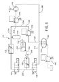
- Figure 6 provides a hydraulic circuit diagram for a second embodiment of the reactive torque control device (38).
- the reactive torque control device (38) may be further comprised of a brake (122) which is associated with the loop (112).
- the brake (122) may be comprised of any structure, device or apparatus which is capable of providing a braking force between the upper assembly (22) and the lower assembly (28) in order to impede or prevent relative rotation between the lower assembly (28) and the upper assembly (22).
- the braking force may be a frictional force, a magnetic force, an electromagnetic force, or a viscous fluid force
- the brake (122) may be comprised of any suitable braking mechanism and/or a clutch mechanism which may be adapted to be associated with the loop (112).
- the brake (122) may be comprised of a first brake part (124) associated with the upper assembly (22) and a second brake part (126) associated with the lower assembly (28).
- the brake (122) may be actuated by a fluid pressure in the loop (112).
- the brake parts (124,126) may be urged into engagement with each other as a result of the fluid pressure in the loop (112), thereby providing an engagement force between the brake parts (124,126) which impedes the relative rotation between the lower assembly (28) and the upper assembly (22).
- the engagement force between the brake parts (124,126) may increase as the fluid pressure in the loop (112) increases.
- the pumping resistance (116) in the loop (112) may be comprised of a first flow restrictor (130) positioned in the loop (112) on an upstream side of the brake (122) and a second flow restrictor (132) positioned in the loop (112) on a downstream side of the brake (122).
- the reactive torque control device (38) may be comprised of a first valve (134) positioned in the loop (112) on the upstream side of the brake (122) and a second valve (136) positioned in the loop (112) on the downstream side of the brake (122).
- the valves (134,136) may each be actuated between an open position and a closed position in which the loop (112) is blocked between the first valve (134) and the second valve (136) in order to maintain the engagement force between the brake parts (124,126).
- the valves (134,136) may be actuatable by the reactive torque control device controller (72).
- the loop (112) may be comprised of a pressure relief bypass line (138) positioned in the loop (112), for bypassing the first valve (134) and the second valve (136) when the fluid pressure in the loop (112) exceeds a bypass pressure as determined by the pressure relief bypass line (138).
- the pressure relief bypass line (138) leads to the low pressure reservoir (140) which provides the pumping fluid (114) to the pump (110).
- the loop (112) may be further comprised of a dump valve (142) for releasing an amount of the pumping fluid (114) from the loop (112) when the fluid pressure in the loop (112) exceeds a dump pressure as determined by the dump valve (142).
- the reactive torque control device (38) may be further comprised of an accumulator (144) in communication with the loop (112), for supplying additional pumping fluid (114) to the loop (112) when the fluid pressure in the loop (112) is below an accumulator threshold pressure as determined by the accumulator (144).
- the reactive torque control device (38) may be actuatable between a first position which provides a minimum resistance to relative rotation between the lower assembly (28) and the upper assembly (22), thereby allowing relative rotation between the lower assembly (28) and the upper assembly (22), and a second position which provides a maximum resistance to relative rotation between the lower assembly (28) and the upper assembly (22), thereby preventing relative rotation between the lower assembly (28) and the upper assembly (22).
- the reactive torque control device (38) may be actuatable to one or more intermediate positions between the first position and the second position, wherein the intermediate positions provide an intermediate resistance to rotation of the lower assembly (28) relative to the upper assembly (22).
- the intermediate positions may permit the lower assembly (28) to rotate relative to the upper assembly (22) at a rate which is slower than that permitted by the first position.
- the reactive torque control device (38) may be actuated amongst the first position, the second position and the intermediate positions by adjusting the pumping resistance (116) in the loop (112) and/or by actuating the one or more valves (120,134,136).
- the feedback control system (42) may be further comprised of a memory (148).
- the memory (148) may be used to store any desired data, including data relating to the apparatus (20) and/or its operation, the borehole (10) and/or surrounding formations, and/or drilling performance.
- the memory (148) may be used to store one or more target orientations of the lower assembly (28), a detailed borehole drilling plan for the apparatus (20), data collected by sensing devices (40,98) during the operation of the apparatus (20), or instructions in downlink communications provided from the surface location (12) during operation of the apparatus (20).
- the data may be stored in the memory (148) for later retrieval when the apparatus (20) is returned to the surface location (12), and/or the data may be used by the feedback control system (42) to control the actuation of the reactive torque control device (38).
- the apparatus (20) may be operated in several different modes.
- the apparatus (20) may be operated in a fully automated closed-loop mode in which the feedback control system (42) utilizes data contained in the memory (148), such as a detailed borehole drilling plan including a sequence of target orientations of the lower assembly (28), data received from the orientation sensing device (40) and/or data received from parameter sensing devices (98) in order to control the operation of the apparatus (20) without input or intervention from the surface location (12).
- data contained in the memory (148) such as a detailed borehole drilling plan including a sequence of target orientations of the lower assembly (28), data received from the orientation sensing device (40) and/or data received from parameter sensing devices (98) in order to control the operation of the apparatus (20) without input or intervention from the surface location (12).
- the apparatus (20) may be operated in a fully manual mode in which the reactive torque control device (38) is actuated by commands from the surface location (12), and in which the feedback control system (42) is effectively overridden by the commands.
- the commands from the surface location (12) may follow the interpretation of data contained in uplink communications received at the surface location (12).
- the apparatus (20) may be operated in a variety of semi-automated closed-loop modes in which the feedback control system (42) achieves and maintains the target orientation of the lower assembly (28), but in which downlink communications can be provided to the feedback control system (42) and stored in the memory (148) in the form of downlink instructions relating to updated target orientations or drilling plans, in which the feedback control system (42) can be overridden from the surface location (12), and/or in which uplink communications can be provided to the surface location (12).
- instructions in the form of target orientations and/or a detailed borehole drilling plan may be stored in the memory (148) at the surface location (12) before the apparatus (20) is deployed in the borehole (10), and data from the sensing devices (40,98) may also be stored in the memory (148) during the operation of the apparatus (20).
- the fully automated closed-loop mode there may be no need for either uplink or downlink communications between the apparatus (20) and the surface location (12).
- the apparatus (20) is operated in the fully manual mode or in a semi-automated closed-loop mode, communication between the apparatus (20) and the surface location (12) is necessary.
- the apparatus (20) may be further comprised of a surface communication link (150) between the surface location (12) and the feedback control system (42), for communicating downlink communications and/or uplink communications between the surface location (12) and the feedback control system (42).
- the downlink communications may be comprised of downlink instructions to the feedback control system (42) for actuating the reactive torque control device (38), such as for example one or more target orientations of the lower assembly (28).
- the uplink communications may be comprised of data generated by the orientation sensing device (40) and/or data generated by parameter sensing devices (98).
- the surface communication link (150) may be included as a dedicated component of the apparatus (20). Alternatively, the surface communication link (150) may be provided by a telemetry system of the type which is typically associated with the drilling string (26).
- the surface communication link (150) may be provided by a telemetry system such as a pressure pulse telemetry system, a fluid flowrate telemetry system comprising a turbine and a rotation sensor for sensing a rotational speed of the turbine, an electromagnetic (EM) telemetry system, an acoustic telemetry system, a wireline telemetry system, or any other type of telemetry system which is capable of communicating downlink communications and/or uplink communications between the surface location (12) and the feedback control system (42).
- a telemetry system such as a pressure pulse telemetry system, a fluid flowrate telemetry system comprising a turbine and a rotation sensor for sensing a rotational speed of the turbine, an electromagnetic (EM) telemetry system, an acoustic telemetry system, a wireline telemetry system, or any other type of telemetry system which is capable of communicating downlink communications and/or uplink communications between the surface location (12) and the feedback control system (42).
- EM electromagnetic
- the telemetry system may be of the type typically described as a measurement-while-drilling (MWD) telemetry system, a logging-while-drilling (LWD) telemetry system or any other suitable type of telemetry system.
- MWD measurement-while-drilling
- LWD logging-while-drilling
- the telemetry system may be comprised of a telemetry system processor, and in some embodiments the feedback processor (70) may be comprised of the telemetry system processor so that the apparatus (20) does not include a dedicated feedback processor (70).
- the telemetry system may be comprised of a telemetry system orientation sensor, and in some embodiments the orientation sensing device (40) may be comprised of the telemetry system orientation sensor so that the apparatus (20) does not include a dedicated orientation sensor (90).
- the telemetry system communicates with the feedback control system (42) and the orientation sensing device (40) which are included as dedicated components of the apparatus (20).
- Figure 7 is a longitudinal section assembly drawing of one example of an embodiment of the apparatus (20), which provides a detailed view of the components of the exemplary apparatus (20).
- Figure 8 is a pictorial schematic drawing of components of the reactive torque control device (38), shown in isolation from the remainder of the apparatus (20).
- Figure 9 is a pictorial schematic drawing of components of the reactive torque control device (38), shown in isolation from the remainder of the apparatus (20) and rotated approximately 180 degrees relative to Figure 8 .
- the upper assembly (22) is comprised of several components connected end to end with threaded connections. Beginning at the upper end (24) of the upper assembly (22), the upper assembly (22) includes a sonde sub (160), an orientation sensing assembly (162), a pump assembly (164), and a brake assembly (166).
- the components (160,162,164,166) are each comprised of housings which define and/or contain parts and features of the apparatus (20). Each of the components (160,162,164,166) may be comprised of a single housing or may be comprised of a plurality of housing elements connected together.
- the sonde sub (160) is comprised of a single sonde sub housing (161)
- the orientation sensing assembly (162) is comprised of a single orientation sensing assembly housing (163)
- the pump assembly (164) is comprised of a loop housing (165a) and a pump housing (165b)
- the brake assembly (166) is comprised of a brake housing (167a), a bearing housing (167b) and a seal housing (167c).
- the lower assembly (28) is comprised of an upper mandrel (170) and a lower mandrel (172) which are connected together with a threaded connection and which are rotatably mounted within the upper assembly (22) so that the upper end of the upper mandrel (170) is contained within the orientation sensing assembly (162) and so that the lower end of the lower mandrel (172) protrudes from the lower end of the brake assembly (166).
- the lower assembly (28) is mounted within the upper assembly (22) with an upper bearing (174) and an upper rotary seal (176) which are contained within the orientation sensing assembly (162) and with a plurality of lower bearings (178) and a lower rotary seal (180) which are contained within the brake assembly (166).
- the bearings (174,178) are comprised of thrust bearings and radial bearings and facilitate the orientable rotatable connection (36) between the upper assembly (22) and the lower assembly (28). As depicted in Figure 7 , the bearings (174,178) include KalsiTM thrust bearings manufactured by Kalsi Engineering, Inc. of Sugar Land, Texas.
- the seals (176,180) provide a fluid chamber (182) within the apparatus (20) between the seals (176,180) which is isolated from fluids in the borehole (10).
- the fluid chamber (182) is contained with pumping fluid (114), which pumping fluid (114) also functions to lubricate components of the apparatus (20).
- the lower assembly (28) further comprises a rotary drilling motor (30) which is threadably connected to the lower end of the lower mandrel (172) and a drill bit (32) which is threadably connected to the lower end of the drilling motor (30).
- a rotary drilling motor (30) which is threadably connected to the lower end of the lower mandrel (172)
- a drill bit (32) which is threadably connected to the lower end of the drilling motor (30).
- Neither the drilling motor (30) nor the drill bit (32) are depicted in Figure 7 , but are depicted in Figures 1-4 .
- the sonde sub (160) may be connected directly with a drilling string (26).
- the sonde sub (160) may be connected with a surface communication link (150) such as a conventional measurement-while-drilling (MWD) module (which is not shown in Figure 7 , but is depicted in Figures 1-4 ) via an adapter (190) on the sonde sub (160), in which case the surface communication link (150) provides the upper end (24) of the upper assembly (24) and is connected with the drilling string (26).
- a surface communication link (150) such as a conventional measurement-while-drilling (MWD) module (which is not shown in Figure 7 , but is depicted in Figures 1-4 )
- MWD measurement-while-drilling
- the sonde sub (160) may be a conventional electronics sub as is known in the field of well logging.
- the functions of the sonde sub (160) include providing components of the feedback control system (42) and providing communication between the surface communication link (150) and other components of the apparatus (20) which are located below the sonde sub (160).
- the sonde sub (160) contains the feedback control system (42), including the feedback processor (70) and the reactive torque control device controller (72), and provides a portion of the feedback communication link (74) between the orientation sensing device (40) and the feedback processor (70).
- the sonde sub (160) also contains the memory (148).
- the memory (148) is connected with the feedback processor (70).
- the orientation sensing assembly (162) is connected to the lower end of the sonde sub (160).
- the primary function of the orientation sensing assembly (162) is to contain the orientation sensing device (40).
- the orientation sensing assembly (162) also provides a communication link between the feedback control system (42) and the reactive torque control device (38).
- the orientation sensing device (40) is comprised of an orientation sensor (90) which is comprised of a conventional electronic orientation sensor package containing accelerometers and/or magnetometers, of the type known in the field of drilling tools. Since the orientation sensor (90) is located on the upper assembly (22), it senses the actual orientation of the upper assembly (22). Consequently, the orientation sensing device (40) is further comprised of a referencing device (96) for providing a referencing orientation between the upper assembly (22) and the lower assembly (28).
- an orientation sensor (90) which is comprised of a conventional electronic orientation sensor package containing accelerometers and/or magnetometers, of the type known in the field of drilling tools. Since the orientation sensor (90) is located on the upper assembly (22), it senses the actual orientation of the upper assembly (22). Consequently, the orientation sensing device (40) is further comprised of a referencing device (96) for providing a referencing orientation between the upper assembly (22) and the lower assembly (28).
- the referencing device (96) is comprised of a resolver.
- the resolver is comprised of an inner ring and an outer ring.
- the inner ring is mounted on the upper mandrel (170) and the outer ring is mounted on the orientation sensing assembly (162).
- the relative positions of the rings provide the reference orientation between the upper assembly (22) and the lower assembly (28).
- the orientation sensing device (40) therefore senses the actual orientation of the upper assembly (22) and senses a reference orientation between the upper assembly (22) and the lower assembly (28) so that the actual orientation of the lower assembly (28) can be determined.
- the pump assembly (164) is connected to the lower end of the orientation sensing assembly (162).
- the primary function of the pump assembly (164) is to contain components of the reactive torque control device (38).
- An upper pressure compensation assembly (200) is also provided between the orientation sensing assembly (162) and the pump assembly (164).
- the upper pressure balancing assembly (200) comprising a pressure balancing chamber and a pressure balancing piston contained within the pressure balancing chamber.
- a fluid chamber side of the pressure balancing chamber is in fluid communication with the fluid chamber (182) and a borehole side of the pressure balancing chamber is in fluid communication with the borehole (10) so that the pressure within the borehole (10) is communicated to the fluid chamber (182) by the pressure balancing piston, thereby reducing the pressure differential across the seals (176,180).
- a spring (202) is provided in the borehole side of the pressure balancing chamber to provide a positive pressure differential between the fluid chamber (182) and the borehole (10).
- the reactive torque control device (38) for the embodiment depicted in Figures 7-9 is essentially identical to the reactive torque control device (38) depicted in Figure 6 and discussed above. Referring to Figures 7-9 , the reactive torque control device (38) therefore includes the pump (110), the loop (112), the brake (122), the first flow restrictor (130), the second flow restrictor (132), the first valve (134), the second valve (136), the pressure relief bypass line (138), the reservoir (140), the dump valve (142) and the accumulator (144).
- the pump (110) is a swash plate pump comprising six cylinders spaced circumferentially around the pump sub (164) so that the pump (110) is driven by relative rotation between the lower assembly (28) and the upper assembly (22).
- the loop (112) is primarily comprised of a collection of ports and channels contained within or formed by the pump sub (164).
- the flow restrictors (130,132) are both Flosert TM adjustable flow restrictors manufactured by The Lee Company, USA of Westport, Connecticut.
- the Flosert TM adjustable flow restrictors provide a constant flow rate over a wide range of pressure conditions, and can be adjusted to provide different flow rates.
- the flow restrictors (130,132) may be adjusted to provide the same flow rates, thereby providing the same flow rate of the pumping fluid (114) toward the brake (122) as away from the brake (122).
- the flow restrictors (130,132) are manually adjustable to provide a desired flow rate and thus a desired pumping resistance (116) before the apparatus (20) is deployed in the borehole (10).
- the flow restrictors (130,132) could, however be configured to be adjustable by the reactive torque control device controller (72).
- valves (134,136) are both solenoid type valves which are electrically actuatable by the reactive torque control device controller (72).
- the loop (112) begins with the pump (112).
- the pumping fluid (114) is drawn from the reservoir (140) and pumped by the pump (110) via a reservoir supply line (208) as the lower assembly (28) rotates relative to the upper assembly (22).
- the pumping fluid (114) passes through check valves (210) to a 360° (i.e., circular) manifold (212). Two lines extend from the manifold (212).
- a first manifold line (214) extends between the manifold (212) and the first valve (134).
- the first flow restrictor (130) is positioned within the first manifold line (214) in order to control the flow rate of the pumping fluid (114) and to assist in providing the pumping resistance (116).
- a second manifold line (216) extends between the manifold (212) and a pressure relief bypass valve (218) so that the second manifold line (216) and the pressure relief bypass valve (218) together provide the pressure relief bypass line (138).
- two pressure relief bypass lines (138) are provided as redundant components.
- the reservoir (140) is comprised of the annular space which is provided between the upper assembly (22) and the lower assembly (28) along the length of the apparatus (20) between the seals (176,180).
- the pumping fluid (114) passes from the second manifold line (216) to a brake actuation line (220) which extends between the first valve (134) and the second valve (136).
- a brake pressure line (222) extends between the brake actuation line (220) and a brake piston (224) so that the fluid pressure in the brake pressure line (222) is equal to the fluid pressure in the brake actuation line (220).
- the brake piston (224) and the brake (122) are contained in the brake assembly (166).
- the brake piston (224) abuts the first brake part (124) such that movement of the brake piston (224) in the brake pressure line (222) under the influence of fluid pressure in the brake actuation line (220) urges the first brake part (124) toward the second brake part (126), thereby providing an engagement force between the brake parts (124,126).
- the first brake part (124) is keyed to the upper assembly (22) so that it may reciprocate relative to the upper assembly (22) but may not rotate relative to the upper assembly (22). As the fluid pressure in the brake actuation line (220) increases, the engagement force between the brake parts (124,126) also increases.
- the second flow restrictor (132) is positioned within the brake pressure line (222) between the brake (122) and the second valve (136) in order to control the flow rate of the pumping fluid (114) between the brake (122) and the reservoir (140) and in order to provide the pumping resistance (116).
- the pumping fluid (214) will continue to pass through the pressure relief bypass valve (218) to the reservoir (140), with the result that the fluid pressure in the brake actuation line (220) will not exceed the bypass pressure.
- the pumping fluid (214) will pass from the brake actuation line (220) and the brake pressure line (222) back to the reservoir (140) via a reservoir return line (225).
- the second flow restrictor (132) limits the flow rate of the pumping fluid through the brake actuation line (220) and assists in providing the pumping resistance (116).
- a pressure transducer (226) is positioned in the brake pressure line (222).
- the pressure transducer (226) senses the fluid pressure in the brake pressure line (222), which can be correlated to the engagement force between the brake parts (124,126).
- the pressure transducer (226) may also be connected with the feedback processor (70) so that the reactive torque control device (38) can be actuated in response to the fluid pressure in the brake pressure line (222).
- the reactive torque control device (38) is further comprised of a first loop pressure compensation assembly (230) and a second loop pressure compensation assembly (232), each of which is similar in design to the upper pressure compensation assembly (200).
- the first loop pressure compensation assembly (230) communicates the pressure in the borehole (10) to the portion of the loop (112) which is between the pump (110) and the first valve (134).
- the second loop pressure compensation assembly (232) communicates the pressure in the borehole (10) to the portion of the loop (112) which is between the second valve (136) and the reservoir (140).
- the lower bearing (178) is contained within the bearing housing (167b) of the brake assembly (166).
- the lower seal (180) is contained within the seal housing (167c) of the brake assembly (166).
- the lower end of the lower mandrel (172) of the lower assembly (28) extends below the lower end of the seal housing (167c) of the brake assembly (166).
- the drilling motor (30) is directly or indirectly connected to the lower end of the lower mandrel (172) and the drill bit (32) is directly or indirectly connected to the lower end of the drilling motor (30) so that the lower assembly (28) is comprised of the drilling motor (30) and the drill bit (32).
- the lower assembly (28) provides the toolface orientation (44), which in turn may be provided by a bend (46) in the lower mandrel (172), by a bend in the drilling motor (30), by a bent sub which is connected within the lower assembly (28), by a steering tool (48), or in any other suitable manner.
- the reactive torque control device (38) may be selectively actuated by the reactive torque control device controller (72) either to allow rotation of the lower assembly (28) relative to the upper assembly (22) or to prevent rotation of the lower assembly (28) relative to the upper assembly (22).
- the reactive torque control device (38) is actuated to allow relative rotation of the lower assembly (28) and the upper assembly (22)
- nondirectional or "straight" drilling is facilitated.
- the reactive torque control device (38) is actuated to prevent relative rotation of the lower assembly (28) and the upper assembly (22)
- directional drilling is facilitated by establishing and maintaining a desired toolface orientation (44) and thus a target orientation of the lower assembly (28).
- the desired toolface orientation (44) (i.e., the target orientation of the lower assembly (28)) may be constant throughout drilling of the borehole (10) or may vary during drilling of the borehole (10) to provide a plurality and/or sequence of target orientations of the lower assembly (28) as part of a borehole drilling plan.
- the desired toolface orientation (44) may be stored in the memory (148) before deployment of the apparatus (20) or may be communicated to the feedback control system (42) and stored in the memory (148) as a downlink instruction via the surface communication link (150).
- a varied target orientation of the lower assembly (28) may be considered to be an updated target orientation of the lower assembly (28).
- the desired toolface orientation (44) may also vary during drilling of the borehole (10) as a result of data received by the feedback control system (42) from parameter sensing devices (98) associated with the apparatus (20). For example, data relating to the composition or condition of formations being intersected during drilling, or data relating to the performance or condition of the apparatus (20) may necessitate or render desirable a change in the desired toolface orientation (44).
- the apparatus (20) or other devices having certain features of the apparatus (20) may be used to perform methods of directional drilling.
- embodiments of a method of directional drilling of a borehole may use an apparatus (20) comprising an upper assembly (22) connected with a drilling string (26), a lower assembly (28) comprising a rotary drilling motor (30) such that the lower assembly (28) is subjected to reactive torque during drilling as a result of the operation of the drilling motor (30), an orientable rotatable connection (36) between the upper assembly (22) and the lower assembly (28), and a reactive torque control device (38) associated with the orientable rotatable connection (36), wherein the reactive torque control device (38) is actuatable to selectively allow rotation of the lower assembly (28) relative to the upper assembly (22) or prevent rotation of the lower assembly (28) relative to the upper assembly (22).
- the apparatus (20) may also include other features as described above with respect to the apparatus (20) of the invention.
- the method may comprise:
- All or portions of the above described method may be repeated while directional drilling is being performed in order to maintain the target orientation of the lower assembly (28) and/or in order to obtain and/or maintain updated target orientations of the lower assembly (28).
- the reactive torque control device (38) may be actuated to allow rotation of the lower assembly (28) relative to the upper assembly (22) by providing a fluid pressure in the brake pressure line (222) which is less than a locking pressure which is required to provide an engagement force between the brake parts (124,126) which is less than that which is required to prevent relative rotation of the lower assembly (28) and the upper assembly (22).
- Such a fluid pressure may be achieved by selectively actuating the valves (134,136).
- the first valve (134) may be actuated to the closed position while the second valve (136) is actuated to the open position.
- both valves (134,136) may be actuated to the closed position while the fluid pressure in the brake pressure line (222) is less than the locking pressure.
- both valves (134,136) may be actuated to the open position if the pumping resistance (116) in the loop (112) provides a fluid pressure in the brake pressure line (222) while the pumping fluid (114) is being pumped around the loop (112) which is less than the locking pressure.
- the reactive torque control device (38) may be actuated to prevent rotation of the lower assembly (28) relative to the upper assembly (22) by providing a fluid pressure in the brake pressure line (222) which is greater than or equal to a locking pressure which is required to provide an engagement force between the brake parts (124,126) which is greater than that which is required to prevent relative rotation of the lower assembly (28) and the upper assembly (22).
- Such a fluid pressure may be achieved by selectively actuating the valves (134,136).
- the first valve (134) may be actuated to the open position while the second valve (136) is actuated to the closed position, thereby causing the fluid pressure in the brake pressure line (222) to increase to the locking pressure (which locking pressure is less than or equal to the bypass pressure as determined by the pressure relief bypass line (138)).
- the first valve (134) may then be closed in order to "trap" the locking pressure in the brake pressure line (222).
- the reactive torque control device (38) will remain actuated to prevent relative rotation of the lower assembly (28) relative to the upper assembly (22) until the fluid pressure in the brake pressure line (222) is reduced below the locking pressure. This may be achieved by actuating the second valve (136) to the open position in order to permit the pumping fluid (114) to move from the brake pressure line (222) back to the reservoir (140).
Landscapes
- Life Sciences & Earth Sciences (AREA)
- Engineering & Computer Science (AREA)
- Geology (AREA)
- Mining & Mineral Resources (AREA)
- Physics & Mathematics (AREA)
- Environmental & Geological Engineering (AREA)
- Fluid Mechanics (AREA)
- General Life Sciences & Earth Sciences (AREA)
- Geochemistry & Mineralogy (AREA)
- Geophysics (AREA)
- Earth Drilling (AREA)
- Processing Of Stones Or Stones Resemblance Materials (AREA)
Abstract
Description
- An apparatus and a method for use in drilling a borehole.
- Drilling of subterranean boreholes is often performed by rotating a drill bit which is located at a distal end of a drilling string. The drill bit may be rotated by rotating the entire drill string from a surface location and/or by using a rotary drilling motor which is connected with the drilling string and which is located adjacent to the drill bit.
- The drilling string may be made up of individual joints of drilling pipe which are connected together to form the drilling string. Alternatively, the drilling string may be made up of a continuous length of coiled tubing which is stored on a large spool.
- When the drilling string is made up of individual joints of drilling pipe, the entire drill string may be rotated with relative ease using a rotary table or a top drive on the drilling rig. When the drilling string is made up of a continuous length of coiled tubing, it is relatively more difficult to rotate the entire drill string because the spool must also be rotated.
- Drilling while rotating the drill bit only by rotating the entire drilling string is often referred to as "rotary drilling". Drilling while rotating the drill bit only with a rotary drilling motor is often referred to as "sliding drilling". Drilling while rotating the drill bit both by rotating the entire drilling string and with a rotary drilling motor is often referred to as "performance drilling".
- Directional drilling involves "steering" the drill bit so that the drill bit drills along a desired path. Directional drilling therefore requires a mechanism for orienting the drill bit so that it drills along the desired path. The orientation of the drill bit during directional drilling is often referred to as a "toolface orientation".
- Directional drilling may be performed using a bend in the drilling string or using a steering tool which is associated with the drilling string.
- If directional drilling is performed using a bend in the drilling string, the orientation of the bend must be controlled in order to provide a desired toolface orientation. As a result, steering with a bend in the drilling string may typically only be achieved during sliding drilling, since rotary drilling will result in a constant rotation of the bend and constant variation of the toolface orientation.
- If directional drilling is performed using a steering tool, a desired toolface orientation may be achieved either by controlling the actuation of the steering tool or by maintaining the steering device at a fixed actuation and controlling the orientation of the steering tool in a similar manner as performing directional drilling with a bend in the drilling string.
- Once selected, the toolface orientation may change in an undesired manner during drilling due to forces applied to the drill bit and the drilling string. These forces may be forces applied to the drill string from the surface location or may be reactive forces exerted on the drill bit and/or the drilling string by the borehole. As a result, it is often desirable to adjust the toolface orientation during directional drilling from time to time to account for such forces and for resulting undesired changes to the toolface orientation.
- Reactive torque results from a reaction of the borehole to rotation of the drill bit against the distal end of the borehole. Reactive torque tends to rotate the drill bit in a direction opposite to that which is imposed upon the drill bit by rotation of the drill string and/or by a rotary drilling motor. Reactive torque may cause changes in the toolface orientation and also imposes potentially damaging stresses on the drilling string.
- Efforts have been made to provide a drilling apparatus which controls the effects of reactive torque while facilitating directional drilling.
-
U.S. Patent No. 5,485,889 (Gray ) describes a drilling system and method for use with coiled tubing. The drilling system includes a control device. The control device includes a downstream section which is connected to a drilling tool having a bend axis, an upstream section which is connected to coiled tubing, and a swivel coupling assembly which connects the downstream section and the upstream section. A pump and a circuit are associated with the downstream section, the upstream section and the swivel coupling assembly so that relative rotation between the downstream section and the upstream section causes the pump to pump fluid through the circuit. A flow restricting orifice and a valve are provided in the circuit. The control device may be actuated to form a straight section of a borehole and a curved section of the borehole. In order to form the straight section of the borehole, the control device is actuated to permit relative rotation of the downstream section and the upstream section at a rate which is less than the rate of rotation of the drill bit. In order to form the curved section of the borehole, the control device is actuated to prevent relative rotation of the downstream section and the upstream section, thereby facilitating orientation of the bend axis of the drilling tool. Actuation of the control device to prevent relative rotation of the downstream section and the upstream section is achieved by actuating the valve to a closed position so that circulation of fluid through the circuit is prevented. The valve is actuated from the surface location through a control cable which extends to the surface location. A sensor communicates through the control cable with the surface location in order to communicate unspecified information to the surface location. -
U.S. Patent No. 6,059,050 (Gray ) describes an apparatus for controlling relative rotation of a drilling tool due to reactive torque. The apparatus includes a first member and a second member which are relatively rotatable and a hydraulic pump having a first pump part mounted on the first member and a second pump part mounted on the second member. The pump is arranged such that relative rotation of the first and second members causes relative rotation of the first and second pump parts, which results in pumping of hydraulic fluid from a first chamber to a second chamber within which the hydraulic fluid is under pressure. A brake having a first brake part on the first member and a second brake part on the second member is associated with the second chamber such that the brake is actuated by the hydraulic pressure in the second chamber. A duct and a variable orifice control the flow of fluid from the second chamber back to the first chamber, thereby controlling the braking force exerted by the brake and the relative rotation of the first and second members. The apparatus may be actuated to permit or prevent relative rotation of the first and second members. Actuation of the apparatus to prevent relative rotation of the first and second members is achieved by actuating the variable orifice to a closed position so that the flow of fluid from the second chamber back to the first chamber is prevented. The variable orifice is controlled by an electrical control line from a suitable control system. A sensor communicates through the control cable with the surface location in order to communicate unspecified information to the surface location. -
U.S. Patent No. 6,571,888 (Comeau et al ) describes an apparatus and a method for directional drilling with coiled tubing. The apparatus includes an uphole sub connected to coiled tubing, a downhole sub having a bent housing, a drill bit and a first motor for rotating the drill bit, a rotary connection between the uphole sub and the downhole sub for enabling rotation therebetween, and a clutch positioned between the rotary connection and the uphole sub. The clutch is operable between engaged and disengaged positions using fluid cycles applied alternately to engage and disengage the clutch. In the engaged position of the clutch, the downhole sub is rotatable relative to the uphole sub. In the disengaged position of the clutch, the downhole sub is locked against rotation relative to the uphole sub. The apparatus may be further comprised of a speed reducer for dissipating the reactive torque tending to rotate the downhole sub when the clutch is in the engaged position. - U.S. Patent Application Publication No.
US 2003/0056963 A1 (Wenzel ) describes an apparatus for controlling a downhole drilling motor assembly which includes a tubular housing, a mandrel rotatably mounted within the housing, and an hydraulic damper assembly disposed between the housing and the mandrel. The hydraulic damper assembly limits the rate of rotation of the mandrel within the housing in order to provide a preset resistance to reactive torque. The hydraulic damper assembly includes an annular body which is positioned within an annular chamber between the housing and the mandrel. The annular body is connected with the mandrel with splines so that the annular body rotates with the mandrel and can reciprocate axially relative to the mandrel. A guide track on the exterior surface of the annular body engages with guide members on the housing. The guide track has a zig-zag pattern which causes the annular body to reciprocate axially in the annular chamber as the housing rotates relative to the mandrel. The annular chamber is filled with hydraulic fluid. The annular body is provided with hydraulic valves which provide a restricted flow of the hydraulic fluid through the annular body as the annular body reciprocates within the annular chamber, thereby providing the preset resistance which limits the rate of rotation of the mandrel within the housing. The apparatus may be actuated to permit or prevent rotation of the mandrel within the housing. Actuation of the apparatus to prevent rotation of the mandrel within the housing may be achieved by actuating an annular plug to block the hydraulic valves, by actuating a clutch between the mandrel and the housing to lock the mandrel and housing together, or by actuating an electric valve to block the movement of hydraulic fluid within the annular chamber. - According to the invention there is provided apparatus for use in drilling a borehole, the apparatus comprising:
- (a) an upper assembly which is connectable with a drilling string;
- (b) a lower assembly comprising a rotary drilling motor such that the lower assembly is subjected to a reactive torque during drilling as a result of the operation of the drilling motor;
- (c) an orientable rotatable connection between the upper assembly and the lower assembly;
- (d) a reactive torque control device associated with the orientable rotatable connection, wherein the reactive torque control device is actuatable to selectively allow rotation of the lower assembly relative to the upper assembly or prevent rotation of the lower assembly relative to the upper assembly;
- (e) an orientation sensing device for providing a sensed actual orientation of the lower assembly; and
- (f) a feedback control system associated with the reactive torque control device and the orientation sensing device, for actuating the reactive torque control device in response to the sensed actual orientation of the lower assembly in order to achieve a target orientation of the lower assembly.
- The feedback control system is typically comprised of a feedback processor for processing the sensed actual orientation of the lower assembly in order to generate a feedback actuation instruction for actuating the reactive torque control device in order to achieve the target orientation of the lower assembly.
- The feedback control system may include a reactive torque control device controller for receiving the feedback actuation instruction and for actuating the reactive torque control device in order to implement the feedback actuation instruction.
- The feedback control system may include a feedback communication link between the orientation sensing device and the feedback processor, for transmitting the sensed actual orientation of the lower assembly from the orientation sensing device to the feedback processor.
- The lower assembly may provide a toolface orientation for facilitating directional drilling.
- The toolface orientation is optionally provided by a bend associated with the lower assembly.
- The orientation sensing device optionally comprises an orientation sensor associated with the lower assembly such that the orientation sensor is a component of the lower assembly.
- The feedback processor is optionally associated with the upper assembly such that the feedback processor is a component of the upper assembly.
- The feedback communication link optionally comprises a wireline between the orientation sensor and the feedback processor.
- The feedback communication link optionally comprises a rotatable signal coupler between the orientation sensor and the feedback processor.
- The rotatable signal coupler typically comprises a slip ring.
- The reactive torque control device typically comprises a pump, which is optionally driven by relative rotation between the lower assembly and the upper assembly.
- The reactive torque control device typically comprises a loop containing a pumping fluid, wherein the relative rotation between the lower assembly and the upper assembly causes the pump to pump the pumping fluid around the loop, wherein the loop comprises a pumping resistance, and wherein the pumping resistance loads the pump and thereby impedes the relative rotation between the lower assembly and the upper assembly.
- The pumping resistance is typically adjustable, and optionally can comprise a flow restrictor positioned in the loop. Optionally the flow restrictor is adjustable, typically by the reactive torque control device controller.
- The loop may be selectively blocked in order to prevent the pumping fluid from being pumped around the loop by the pump.
- The reactive torque control device typically comprises a valve positioned in the loop and the valve may optionally be actuated between an open position and a closed position in which the loop is blocked in order to prevent the pumping fluid from being pumped around the loop by the pump.
- The valve is optionally actuatable by the reactive torque control device controller.
- The pump is typically a swash plate pump.
- The reactive torque control device typically comprises a brake associated with the loop, wherein the brake is comprised of a first brake part associated with the upper assembly and a second brake part associated with the lower assembly, and wherein the brake is actuated by a fluid pressure in the loop.
- The first brake part and the second brake part are optionally urged into engagement with each other as a result of the fluid pressure in the loop, thereby providing an engagement force between the first brake part and the second brake part which impedes the relative rotation between the lower assembly and the upper assembly, and wherein the engagement force between the first brake part and the second brake part increases as the fluid pressure in the loop increases.
- Optionally the pumping resistance is comprised of a first flow restrictor positioned in the loop on an upstream side of the brake and a second flow restrictor positioned in the loop on a downstream side of the brake.
- The reactive torque control device typically comprises a first valve positioned in the loop on an upstream side of the brake and a second valve positioned in the loop on a downstream side of the brake, and typically the first valve and the second valve may each be actuated between an open position and a closed position in which the loop is blocked between the first valve and the second valve in order to maintain the engagement force between the first brake part and the second brake part.
- Typically the loop is comprised of a pressure relief bypass line positioned in the loop for bypassing the first valve and the second valve when the fluid pressure in the loop exceeds a bypass pressure as determined by the pressure relief bypass line.
- The loop typically comprises a dump valve for releasing an amount of the pumping fluid from the loop when the fluid pressure in the loop exceeds a dump pressure as determined by the dump valve.
- The reactive torque control device typically comprises an accumulator in communication with the loop, for supplying additional pumping fluid to the loop when the fluid pressure in the loop is below an accumulator threshold pressure as determined by the accumulator.
- The first valve and the second valve are typically both actuatable by the reactive torque control device controller.
- The orientation sensing device typically comprises an orientation sensor associated with the upper assembly such that the orientation sensor is a component of the upper assembly and such that the orientation sensor provides a sensed actual orientation of the upper assembly.
- The orientation sensing device typically comprises a referencing device for providing a reference orientation between the upper assembly and the lower assembly so that the sensed actual orientation of the lower assembly can be obtained from the sensed actual orientation of the upper assembly.
- The feedback processor is typically associated with the upper assembly such that the feedback processor is a component of the upper assembly.
- The reactive torque control device controller is typically associated with the upper assembly such that the reactive torque control device controller is a component of the upper assembly.
- The feedback control system typically comprises a memory for storing the target orientation of the lower assembly.
- Typically the apparatus includes a surface communication link between a surface location and the feedback control system, for communicating a downlink instruction from the surface location to the feedback control system. Optionally the surface communication link communicates an uplink communication from the feedback control system to the surface location. The surface communication link typically comprises a measurement-while-drilling telemetry system, and may comprise a pressure pulse telemetry system.
- The surface communication link typically comprises a fluid flowrate telemetry system comprising a turbine and a rotation sensor for sensing a rotational speed of the turbine.
- The feedback control system typically comprises a memory for storing the downlink instruction.
- The downlink instruction typically comprises the target orientation of the lower assembly.
- The drilling string typically comprises a section of coiled tubing and the upper assembly is optionally connected with the coiled tubing.
- The upper assembly typically comprises an upper section, a lower section adjacent to the orientable rotatable connection, and a swivel connection between the upper section and the lower section so that the upper section is rotatable relative to the lower section.
- The lower section of the upper assembly typically comprises a rotation restraining device for restraining the lower section of the upper assembly from rotating relative to the borehole.
- The reactive torque control device is typically actuatable between a first position which provides a minimum resistance to rotation of the lower assembly relative to the upper assembly and a second position which provides a maximum resistance to rotation of the lower assembly relative to the upper assembly, wherein rotation of the lower assembly relative to the upper assembly is allowed when the reactive torque control device is actuated to the first position, and wherein rotation of the lower assembly relative to the upper assembly is prevented when the reactive torque control device is actuated to the second position.
- The reactive torque control device is optionally actuatable to at least one intermediate position between the first position and the second position, which intermediate position provides an intermediate resistance to rotation of the lower assembly relative to the upper assembly.
- The reactive torque control device is optionally actuatable to a plurality of intermediate positions between the first position and the second position in order to provide a variable intermediate resistance to rotation of the lower assembly relative to the upper assembly.
- The apparatus can optionally include at least one parameter sensing device, for sensing a parameter other than the actual orientation of the lower assembly and for providing a sensed parameter value relating to the parameter. The at least one parameter sensing device can optionally be associated with the feedback control system so that the feedback control system actuates the reactive torque control device in response to the sensed parameter value.
- The invention also provides a method of directional drilling of a borehole using an apparatus comprising an upper assembly connected with a drilling string, a lower assembly comprising a rotary drilling motor such that the lower assembly is subjected to reactive torque during drilling as a result of the operation of the drilling motor, an orientable rotatable connection between the upper assembly and the lower assembly, and a reactive torque control device associated with the orientable rotatable connection, wherein the reactive torque control device is actuatable to selectively allow rotation of the lower assembly relative to the upper assembly or prevent rotation of the lower assembly relative to the upper assembly, the method comprising the following:
- (a) actuating the reactive torque control device to prevent rotation of the lower assembly relative to the upper assembly;
- (b) providing a sensed actual orientation of the lower assembly;
- (c) comparing the sensed actual orientation of the lower assembly with a target orientation of the lower assembly;
- (d) actuating the reactive torque control device to allow the lower assembly to rotate relative to the upper assembly;
- (e) operating the drilling motor in order to provide the target orientation of the lower assembly; and
- (f) actuating the reactive torque control device to prevent rotation of the lower assembly relative to the upper assembly.
- Features of the invention described with reference to the apparatus of the invention can be combined or used with any aspects of the method of the invention. Features and steps of the invention described with reference to the method of the invention can be combined or used with any aspects of the apparatus of the invention.
- The upper assembly typically comprises an upper section, a lower section adjacent to the orientable rotatable connection, and a swivel connection between the upper section and the lower section so that the upper section is rotatable relative to the lower section, further comprising rotating the upper section of the upper assembly while operating the drilling motor.
- The method may include the additional optional step of restraining the lower section of the upper assembly from rotating relative to the borehole.
- The method may include the additional optional step of communicating a downlink instruction to the apparatus, wherein the downlink instruction is comprised of the target orientation of the lower assembly.
- The method may include the additional optional step of repeating (b) through (f) while the directional drilling is being performed.
- The method may include the additional optional step of communicating a downlink instruction to the apparatus periodically while the directional drilling is being performed, wherein the downlink instruction is comprised of the target orientation of the lower assembly.
- Optionally the target orientation of the lower assembly is an updated target orientation of the lower assembly.
- Optionally the downlink instruction is comprised of a sequence of target orientations of the lower assembly.
- Optionally the sensed actual orientation of the lower assembly is provided by obtaining a sensed actual orientation of the upper assembly and a reference orientation between the upper assembly and the lower assembly.
- The method may include the additional optional step of communicating an uplink communication from the apparatus, wherein the uplink communication is comprised of the sensed actual orientation of the lower assembly.
- The method may include the additional optional step of communicating a downlink instruction to the apparatus, wherein the downlink instruction is comprised of the target orientation of the lower assembly.
- Typically the reactive torque control device is actuatable between a first position which provides a minimum resistance to rotation of the lower assembly relative to the upper assembly and a second position which provides a maximum resistance to rotation of the lower assembly relative to the upper assembly and wherein actuating the reactive torque control device to prevent rotation of the lower assembly relative to the upper assembly is comprised of actuating the reactive torque control device to the second position.
- Typically the reactive torque control device is actuatable to at least one intermediate position between the first position and the second position, which intermediate position provides an intermediate resistance to rotation of the lower assembly relative to the upper assembly, and wherein actuating the reactive torque control device to allow the lower assembly to rotate relative to the upper assembly is comprised of actuating the reactive torque control system to the intermediate position.
- Typically the reactive torque control device is actuatable to a plurality of intermediate positions between the first position and the second position in order to provide a variable intermediate resistance to rotation of the lower assembly relative to the upper assembly, and wherein actuating the reactive torque control device to allow the lower assembly to rotate relative to the upper assembly is comprised of actuating the reactive torque control device to one of the intermediated positions.
- The method of the invention can optionally be performed with steps (b) to (f) being repeated using an updated target orientation of the lower assembly, and including the optional additional step of generating the updated target orientation of the lower assembly.
- The updated target orientation of the lower assembly is typically generated using data from at least one sensing device associated with the apparatus.
- The updated target orientation of the lower assembly is typically generated by the feedback control system.
- Embodiments of the invention will now be described with reference to the accompanying drawings, in which:
-
Figure 1 is a schematic drawing of one embodiment of the apparatus of the invention connected with a drilling string in a borehole. -
Figure 2 is a schematic drawing of a second embodiment of the apparatus of the invention connected with a drilling string in a borehole. -
Figure 3 is a schematic drawing of components of a one embodiment of the apparatus of the invention. -
Figure 4 is a schematic drawing of components of a second embodiment of the apparatus of the invention. -
Figure 5 is a hydraulic circuit diagram relating to a hydraulic circuit for use in one embodiment of a reactive torque control device according to the invention. -
Figure 6 is a hydraulic circuit diagram relating to a hydraulic circuit for use in a second embodiment of a reactive torque control device according to the invention. -
Figure 7 is a longitudinal section assembly drawing of components of an embodiment of the apparatus of the invention, in whichFigure 7B is a continuation ofFigure 7A ,Figure 7C is a continuation of -
Figure 7B ,Figure 7D is a continuation ofFigure 7C ,Figure 7E is a continuation ofFigure 7D , andFigure 7F is a continuation ofFigure 7E . -
Figure 8 is a first pictorial schematic drawing of features of the reactive torque control device in the embodiment of the apparatus of the invention depicted inFigure 7 . -
Figure 9 is a second pictorial schematic drawing of features of the reactive torque control device in the embodiment of the apparatus of the invention depicted inFigure 7 from a different viewing position than that ofFigure 8 . - The present invention is an apparatus and a method for use in drilling a borehole. The invention utilizes reactive torque to control the orientation of one or more components of a drilling string during drilling. The invention is particularly useful for controlling a toolface orientation in directional drilling.
- As used herein, "upper" means relatively proximal and/or uphole and "lower" means relatively distal and/or downhole with respect to position within a drilling string or location within a borehole, relative to a surface location.
-
Figure 1 provides a basic schematic view of one exemplary configuration of equipment which may be used to drill a borehole (10) from a surface location (12), including a schematic depiction of the apparatus (20) of the invention. The surface location (12) may be a ground surface, a drilling platform, or any other location outside of the borehole (10) from which drilling is controlled. - Referring to
Figure 1 , an embodiment of the apparatus (20) of the invention is comprised of an upper assembly (22). The upper assembly (22) has an upper end (24) which is connected with a drilling string (26). - The apparatus is further comprised of a lower assembly (28). The lower assembly (28) includes a rotary drilling motor (30). The drilling motor (30) includes a drill bit (32) which is positioned at a lower end (34) of the lower assembly (28).
- The drilling string (26) may be comprised of a plurality of relatively short joints of pipe which are connected together, may be comprised of a single continuous length of pipe, or may be comprised of relatively long joints or lengths of pipe which are connected together. As depicted in
Figure 1 , the drilling string (26) is comprised of a continuous length of pipe known as coiled tubing (50). As depicted inFigure 2 , the drilling string (26) is comprised of relatively short joints of pipe (51) which are connected together. - Referring to
Figure 1 , the coiled tubing (50) is stored on a spool (52) which is located at the surface location (12). If the length of a single spool (52) of coiled tubing (50) is not sufficient to complete the drilling operation, lengths of coiled tubing (50) may be connected together to form the drilling string (26). - In the embodiment depicted in
Figure 1 , drilling is typically performed as sliding drilling wherein the drill bit (32) is rotated by the drilling motor (30) during drilling and the coiled tubing (50) is not rotated during drilling. - As depicted in
Figure 1 , the upper assembly (22) is configured so that no portion of the upper assembly (22) is rotatable relative to the drilling string (26). - Referring to
Figure 2 , in an alternate embodiment, the upper assembly (22) may be comprised of an upper section (54), a lower section (56) adjacent to the orientable rotatable connection (32), and a swivel connection (58) between the upper section (54) and the lower section (56) so that the upper section (54) is rotatable relative to the lower section (56). In the alternate embodiment depicted inFigure 2 , the lower section (56) may be comprised of a rotation restraining device (60) for restraining the lower section (56) of the lower assembly (28) from rotating relative to the borehole (10) during drilling. - The alternate embodiment depicted in
Figure 2 allows for the drilling string (26) to be rotated from the surface location (12) during drilling without rotating either the lower section (56) of the upper assembly (22) or the lower assembly (28), thus providing some of the known benefits of rotary drilling in the use of the invention. -
Figure 3 and Figure 4 provide more detailed schematic views of embodiments of the apparatus (20) of the invention in which components of the apparatus (20) are more fully depicted. - Referring to both
Figure 3 and Figure 4 , an orientable rotatable connection (36) is provided between the upper assembly (22) and the lower assembly (28). - A reactive torque control device (38) is associated with the orientable rotatable connection (36). The reactive torque control device (38) is actuatable to selectively allow rotation of the lower assembly (28) relative to the upper assembly (22) or prevent rotation of the lower assembly (28) relative to the upper assembly (22).
- An orientation sensing device (40) provides a sensed actual orientation of the lower assembly (28).
- A feedback control system (42) is associated with the reactive torque control device (38) and with the orientation sensing device (40). The feedback control system (42) is capable of actuating the reactive torque control device (38) in response to the sensed actual orientation of the lower assembly (28) in order to achieve a target orientation of the lower assembly (28).
- In some embodiments, the lower assembly (28) provides a toolface orientation (44) to facilitate directional drilling. A desired toolface orientation (44) of the lower assembly (28) may be provided by the target orientation of the lower assembly (28). A desired toolface orientation (44) of the lower assembly (28) may be identical to the target orientation of the lower assembly (28) or may be referenced to the target orientation of the lower assembly (28).
- The toolface orientation (44) may be provided in any manner and/or by any apparatus which enables the lower assembly (28) to provide the toolface orientation (44). For example, the toolface orientation (44) may be provided by a steering tool, where the term "steering tool" includes any apparatus which facilitates directional drilling by providing the toolface orientation (44).
- In some embodiments, the toolface orientation (44) may be provided by a bend (46) associated with the lower assembly (28). The bend (46) may be provided by a bent sub, by a bent motor housing, or may be provided in any other suitable manner.
- The feedback control system (42) may be comprised of any structure, device or apparatus or combination of structures, devices and apparatus which is capable of receiving input from the orientation sensing device (40) relating to the sensed actual orientation of the lower assembly (28) and actuating the reactive torque control device (38) in response to the input in order to achieve the target orientation of the lower assembly (28).
- For example, referring to
Figure 3 and Figure 4 , in some embodiments the feedback control system (42) is comprised of a feedback processor (70) for processing the sensed actual orientation of the lower assembly (28) in order to generate a feedback actuation instruction for actuating the reactive torque control device (38) in order to achieve the target orientation of the lower assembly (28). The feedback control system (42) may also be comprised of a reactive torque control device controller (72) for receiving the feedback actuation instruction and for actuating the reactive torque control device (38) in order to implement the feedback actuation instruction. The feedback control system (42) may also be comprised of a feedback communication link (74) between the orientation sensing device (40) and the feedback processor (70), for transmitting the sensed actual orientation of the lower assembly (28) from the orientation sensing device (40) to the feedback processor (70). - The feedback processor (70) and the reactive torque control device controller (72) may be comprised of separate components or may be combined in a single apparatus or device.
- The components of the feedback control system (42) may be associated with either the upper assembly (22) or the lower assembly (28). As depicted in
Figure 3 and Figure 4 , the components of the feedback control system (42) are associated with the upper assembly (22) so that the feedback control system (42) is a component of the upper assembly (22). - The orientation sensing device (40) may be comprised of any structure, device or apparatus which is capable of sensing the actual orientation of the lower assembly (28). The orientation sensing device (40) may be comprised of an orientation sensor (90). The orientation sensor (90) may be associated with either the upper assembly (22) or the lower assembly (28).
- As previously described, the orientable rotatable connection (36) connects the upper assembly (22) and the lower assembly (28), with the result that the upper assembly (22) and the lower assembly (28) may rotate relative to each other. Consequently, there are advantages and disadvantages inherent in associating the orientation sensor (90) with either the upper assembly (22) or the lower assembly (28).
- As one example, associating the orientation sensor (90) with the lower assembly (28) facilitates a direct determination of the sensed actual orientation of the lower assembly (28), but requires either that the feedback processor (70) be associated with the lower assembly (28) or that the feedback communication link (74) effect communication across the orientable rotatable connection (36). As a second example, associating the orientation sensor (90) with the upper assembly (22) enables the feedback processor (70) to be associated with the upper assembly (22) without requiring the feedback communication link (74) to effect communication across the orientable rotatable connection (36), but results in a sensed actual orientation of the upper assembly (22) which must somehow be referenced to the actual orientation of the lower assembly (28) in order to provide the sensed actual orientation of the lower assembly (28).
- As a result, referring to
Figure 3 , the orientation sensor (90) may be associated with the lower assembly (28) so that the orientation sensor (90) is a component of the lower assembly (28) and the feedback processor (70) is associated with the upper assembly (22) so that the feedback processor (70) is a component of the upper assembly (22). In this configuration, the sensed actual orientation of the lower assembly (28) may be directly determined by the orientation sensor (90), the feedback communication link (74) is comprised of a wireline (i.e., electrical cable) (92) between the orientation sensor (90) and the feedback processor (70), and a rotatable signal coupler (94) is provided between the orientation sensor (90) and the feedback processor (70) in order to effect communication across the orientable rotatable connection (36). - The rotatable signal coupler (94) may be comprised of a slip ring, an inductive coupling, or any other suitable coupler which is capable of communicating signals across the orientable rotatable connection (36). As depicted in
Figure 3 , the rotatable signal coupler (94) is a slip ring. - Referring to
Figure 4 , the orientation sensor (90) may alternatively be associated with the upper assembly (22) so that the orientation sensor (90) is a component of the upper assembly (22) and the feedback processor (70) is associated with the upper assembly (22) so that the feedback processor is a component of the upper assembly (22). In this configuration, the rotatable signal coupler (94) is not necessary, but the orientation sensor (90) provides a sensed actual orientation of the upper assembly (22). As a result, the orientation sensing device (40) is comprised of a referencing device (96) for providing a reference orientation between the upper assembly (22) and the lower assembly (28) so that the sensed actual orientation of the lower assembly (28) can be obtained from the sensed actual orientation of the upper assembly (22). - Referring to
Figure 3 and Figure 4 , the apparatus (20) may be further comprised of one or more parameter sensing devices (98) for sensing parameters other than the actual orientation of the lower assembly (28). Such parameters may relate to the apparatus (20), to the borehole (10) and/or surrounding formations, and/or to drilling performance. The parameter sensing devices (98) may be comprised of any suitable structures, devices or apparatus for sensing the desired parameters. - The reactive torque control device (38) may be associated with either or both of the upper assembly (22) and the lower assembly (28). In some embodiments, the reactive torque control device (38) is associated with the upper assembly (22) so that the reactive torque control device is a component of the upper assembly (22).
- The reactive torque control device (38) may be comprised of any structure, device or apparatus or combination of structures, devices or apparatus which is capable of being actuated to selectively allow rotation of the lower assembly (28) relative to the upper assembly (28) or prevent rotation of the lower assembly (28) relative to the upper assembly (22). For example, the reactive torque control device (38) may be comprised of a device such as those described in
U.S. Patent No. 5,485,889 (Gray ),U.S. Patent No. 6,059,050 (Gray ) or U.S. Pat. App. Pub. No.US 2003/0056963 A1 (Wenzel ). -
Figure 5 provides a hydraulic circuit diagram for a first embodiment of the reactive torque control device (38). - Referring to
Figure 5 , the reactive torque control device (38) may be comprised of a pump (110) and a loop (112) containing a pumping fluid (114), wherein the pump (110) pumps the pumping fluid (114) around the loop (112). As depicted inFigure 5 , the pump (110) is driven by relative rotation between the lower assembly (28) and the upper assembly (22). In other embodiments, the pump (110) may be driven by a power source other than the relative rotation between the lower assembly (28) and the upper assembly (22). - Referring to
Figure 5 , the loop (112) is comprised of a pumping resistance (116). The pumping resistance (116) loads the pump (110) and thereby impedes the relative rotation between the lower assembly (28) and the upper assembly (22). The pumping resistance (116) may be adjustable. The pumping resistance (116) may be comprised of one or more flow restrictors (118) positioned in the loop (112). - The one or more flow restrictors (118) may be adjustable in order to adjust the pumping resistance (116). The one or more flow restrictors (118) may be adjustable by the reactive torque control device controller (72), or may be manually adjustable.
- Referring to
Figure 5 , the loop (112) may be selectively blocked in order to prevent the pumping fluid (114) from being pumped around the loop (112) by the pump (110). The reactive torque control device (38) may therefore be further comprised of one or more valves (120) positioned in the loop (112). The one or more valves (120) may be actuatable between an open position and a closed position in which the loop (112) is blocked in order to prevent the pumping fluid (114) from being pumped around the loop (112) by the pump (110). - The one or more valves (120) may be actuatable by the reactive torque control device controller (72). The one or more valves (120) may be solenoid type valves or any other suitable type of valve.
- The pump (110) may be comprised of any type of pump which is suitable for pumping the pumping fluid around the loop (112). In embodiments where the pump (110) is driven by relative rotation between the lower assembly (28) and the upper assembly (22), the pump (110) may be a swash plate type pump. A low pressure reservoir (140) is included in the loop (112) to provide a source of the pumping fluid (114) for the pump (110).
-
Figure 6 provides a hydraulic circuit diagram for a second embodiment of the reactive torque control device (38). - Referring to
Figure 6 , the reactive torque control device (38) may be further comprised of a brake (122) which is associated with the loop (112). The brake (122) may be comprised of any structure, device or apparatus which is capable of providing a braking force between the upper assembly (22) and the lower assembly (28) in order to impede or prevent relative rotation between the lower assembly (28) and the upper assembly (22). As non-limiting examples, the braking force may be a frictional force, a magnetic force, an electromagnetic force, or a viscous fluid force, and the brake (122) may be comprised of any suitable braking mechanism and/or a clutch mechanism which may be adapted to be associated with the loop (112). - As depicted in
Figure 6 , the brake (122) may be comprised of a first brake part (124) associated with the upper assembly (22) and a second brake part (126) associated with the lower assembly (28). The brake (122) may be actuated by a fluid pressure in the loop (112). The brake parts (124,126) may be urged into engagement with each other as a result of the fluid pressure in the loop (112), thereby providing an engagement force between the brake parts (124,126) which impedes the relative rotation between the lower assembly (28) and the upper assembly (22). The engagement force between the brake parts (124,126) may increase as the fluid pressure in the loop (112) increases. - Referring to
Figure 6 , the pumping resistance (116) in the loop (112) may be comprised of a first flow restrictor (130) positioned in the loop (112) on an upstream side of the brake (122) and a second flow restrictor (132) positioned in the loop (112) on a downstream side of the brake (122). - Referring to
Figure 6 , the reactive torque control device (38) may be comprised of a first valve (134) positioned in the loop (112) on the upstream side of the brake (122) and a second valve (136) positioned in the loop (112) on the downstream side of the brake (122). The valves (134,136) may each be actuated between an open position and a closed position in which the loop (112) is blocked between the first valve (134) and the second valve (136) in order to maintain the engagement force between the brake parts (124,126). The valves (134,136) may be actuatable by the reactive torque control device controller (72). - Referring to
Figure 6 , the loop (112) may be comprised of a pressure relief bypass line (138) positioned in the loop (112), for bypassing the first valve (134) and the second valve (136) when the fluid pressure in the loop (112) exceeds a bypass pressure as determined by the pressure relief bypass line (138). As depicted inFigure 6 , the pressure relief bypass line (138) leads to the low pressure reservoir (140) which provides the pumping fluid (114) to the pump (110). - Referring to
Figure 6 , the loop (112) may be further comprised of a dump valve (142) for releasing an amount of the pumping fluid (114) from the loop (112) when the fluid pressure in the loop (112) exceeds a dump pressure as determined by the dump valve (142). - Referring to
Figure 6 , the reactive torque control device (38) may be further comprised of an accumulator (144) in communication with the loop (112), for supplying additional pumping fluid (114) to the loop (112) when the fluid pressure in the loop (112) is below an accumulator threshold pressure as determined by the accumulator (144). - The reactive torque control device (38) may be actuatable between a first position which provides a minimum resistance to relative rotation between the lower assembly (28) and the upper assembly (22), thereby allowing relative rotation between the lower assembly (28) and the upper assembly (22), and a second position which provides a maximum resistance to relative rotation between the lower assembly (28) and the upper assembly (22), thereby preventing relative rotation between the lower assembly (28) and the upper assembly (22).
- In some embodiments, the reactive torque control device (38) may be actuatable to one or more intermediate positions between the first position and the second position, wherein the intermediate positions provide an intermediate resistance to rotation of the lower assembly (28) relative to the upper assembly (22). The intermediate positions may permit the lower assembly (28) to rotate relative to the upper assembly (22) at a rate which is slower than that permitted by the first position.
- Depending upon the embodiment of the invention, the reactive torque control device (38) may be actuated amongst the first position, the second position and the intermediate positions by adjusting the pumping resistance (116) in the loop (112) and/or by actuating the one or more valves (120,134,136).
- Referring to
Figure 3 and Figure 4 , the feedback control system (42) may be further comprised of a memory (148). The memory (148) may be used to store any desired data, including data relating to the apparatus (20) and/or its operation, the borehole (10) and/or surrounding formations, and/or drilling performance. For example, the memory (148) may be used to store one or more target orientations of the lower assembly (28), a detailed borehole drilling plan for the apparatus (20), data collected by sensing devices (40,98) during the operation of the apparatus (20), or instructions in downlink communications provided from the surface location (12) during operation of the apparatus (20). The data may be stored in the memory (148) for later retrieval when the apparatus (20) is returned to the surface location (12), and/or the data may be used by the feedback control system (42) to control the actuation of the reactive torque control device (38). - The apparatus (20) may be operated in several different modes.
- As one example, the apparatus (20) may be operated in a fully automated closed-loop mode in which the feedback control system (42) utilizes data contained in the memory (148), such as a detailed borehole drilling plan including a sequence of target orientations of the lower assembly (28), data received from the orientation sensing device (40) and/or data received from parameter sensing devices (98) in order to control the operation of the apparatus (20) without input or intervention from the surface location (12).
- As a second example, the apparatus (20) may be operated in a fully manual mode in which the reactive torque control device (38) is actuated by commands from the surface location (12), and in which the feedback control system (42) is effectively overridden by the commands. In this mode, the commands from the surface location (12) may follow the interpretation of data contained in uplink communications received at the surface location (12).
- As a third example, the apparatus (20) may be operated in a variety of semi-automated closed-loop modes in which the feedback control system (42) achieves and maintains the target orientation of the lower assembly (28), but in which downlink communications can be provided to the feedback control system (42) and stored in the memory (148) in the form of downlink instructions relating to updated target orientations or drilling plans, in which the feedback control system (42) can be overridden from the surface location (12), and/or in which uplink communications can be provided to the surface location (12).
- If the apparatus (20) is operated in the fully automated closed-loop mode, instructions in the form of target orientations and/or a detailed borehole drilling plan may be stored in the memory (148) at the surface location (12) before the apparatus (20) is deployed in the borehole (10), and data from the sensing devices (40,98) may also be stored in the memory (148) during the operation of the apparatus (20). As a result, in the fully automated closed-loop mode, there may be no need for either uplink or downlink communications between the apparatus (20) and the surface location (12).
- If, however, the apparatus (20) is operated in the fully manual mode or in a semi-automated closed-loop mode, communication between the apparatus (20) and the surface location (12) is necessary.
- Consequently, referring to
Figure 3 and Figure 4 , in some embodiments the apparatus (20) may be further comprised of a surface communication link (150) between the surface location (12) and the feedback control system (42), for communicating downlink communications and/or uplink communications between the surface location (12) and the feedback control system (42). - The downlink communications may be comprised of downlink instructions to the feedback control system (42) for actuating the reactive torque control device (38), such as for example one or more target orientations of the lower assembly (28).
- The uplink communications may be comprised of data generated by the orientation sensing device (40) and/or data generated by parameter sensing devices (98).
- The surface communication link (150) may be included as a dedicated component of the apparatus (20). Alternatively, the surface communication link (150) may be provided by a telemetry system of the type which is typically associated with the drilling string (26).
- For example, the surface communication link (150) may be provided by a telemetry system such as a pressure pulse telemetry system, a fluid flowrate telemetry system comprising a turbine and a rotation sensor for sensing a rotational speed of the turbine, an electromagnetic (EM) telemetry system, an acoustic telemetry system, a wireline telemetry system, or any other type of telemetry system which is capable of communicating downlink communications and/or uplink communications between the surface location (12) and the feedback control system (42).
- The telemetry system may be of the type typically described as a measurement-while-drilling (MWD) telemetry system, a logging-while-drilling (LWD) telemetry system or any other suitable type of telemetry system.
- The telemetry system may be comprised of a telemetry system processor, and in some embodiments the feedback processor (70) may be comprised of the telemetry system processor so that the apparatus (20) does not include a dedicated feedback processor (70).
- The telemetry system may be comprised of a telemetry system orientation sensor, and in some embodiments the orientation sensing device (40) may be comprised of the telemetry system orientation sensor so that the apparatus (20) does not include a dedicated orientation sensor (90).
- In other embodiments, the telemetry system communicates with the feedback control system (42) and the orientation sensing device (40) which are included as dedicated components of the apparatus (20).
-
Figure 7 is a longitudinal section assembly drawing of one example of an embodiment of the apparatus (20), which provides a detailed view of the components of the exemplary apparatus (20).Figure 8 is a pictorial schematic drawing of components of the reactive torque control device (38), shown in isolation from the remainder of the apparatus (20).Figure 9 is a pictorial schematic drawing of components of the reactive torque control device (38), shown in isolation from the remainder of the apparatus (20) and rotated approximately 180 degrees relative toFigure 8 . - The reference numbers used above will be used in the description that follows to the extent that the previously used reference numbers relate to equivalent structures in the particular embodiment.
- Referring to
Figure 7 , the upper assembly (22) is comprised of several components connected end to end with threaded connections. Beginning at the upper end (24) of the upper assembly (22), the upper assembly (22) includes a sonde sub (160), an orientation sensing assembly (162), a pump assembly (164), and a brake assembly (166). The components (160,162,164,166) are each comprised of housings which define and/or contain parts and features of the apparatus (20). Each of the components (160,162,164,166) may be comprised of a single housing or may be comprised of a plurality of housing elements connected together. - As depicted in
Figure 7 , the sonde sub (160) is comprised of a single sonde sub housing (161), the orientation sensing assembly (162) is comprised of a single orientation sensing assembly housing (163), the pump assembly (164) is comprised of a loop housing (165a) and a pump housing (165b), and the brake assembly (166) is comprised of a brake housing (167a), a bearing housing (167b) and a seal housing (167c). - The lower assembly (28) is comprised of an upper mandrel (170) and a lower mandrel (172) which are connected together with a threaded connection and which are rotatably mounted within the upper assembly (22) so that the upper end of the upper mandrel (170) is contained within the orientation sensing assembly (162) and so that the lower end of the lower mandrel (172) protrudes from the lower end of the brake assembly (166).
- The lower assembly (28) is mounted within the upper assembly (22) with an upper bearing (174) and an upper rotary seal (176) which are contained within the orientation sensing assembly (162) and with a plurality of lower bearings (178) and a lower rotary seal (180) which are contained within the brake assembly (166). The bearings (174,178) are comprised of thrust bearings and radial bearings and facilitate the orientable rotatable connection (36) between the upper assembly (22) and the lower assembly (28). As depicted in
Figure 7 , the bearings (174,178) include Kalsi™ thrust bearings manufactured by Kalsi Engineering, Inc. of Sugar Land, Texas. - The seals (176,180) provide a fluid chamber (182) within the apparatus (20) between the seals (176,180) which is isolated from fluids in the borehole (10). The fluid chamber (182) is contained with pumping fluid (114), which pumping fluid (114) also functions to lubricate components of the apparatus (20).
- The lower assembly (28) further comprises a rotary drilling motor (30) which is threadably connected to the lower end of the lower mandrel (172) and a drill bit (32) which is threadably connected to the lower end of the drilling motor (30). Neither the drilling motor (30) nor the drill bit (32) are depicted in
Figure 7 , but are depicted inFigures 1-4 . - If the apparatus (20) is to be operated in a fully automated closed-loop mode and no downlink or uplink communications between the apparatus (20) and the surface location (12) are required, the sonde sub (160) may be connected directly with a drilling string (26).
- If however, it is necessary or desirable to provide for downlink and/or uplink communications, the sonde sub (160) may be connected with a surface communication link (150) such as a conventional measurement-while-drilling (MWD) module (which is not shown in
Figure 7 , but is depicted inFigures 1-4 ) via an adapter (190) on the sonde sub (160), in which case the surface communication link (150) provides the upper end (24) of the upper assembly (24) and is connected with the drilling string (26). - The sonde sub (160) may be a conventional electronics sub as is known in the field of well logging. The functions of the sonde sub (160) include providing components of the feedback control system (42) and providing communication between the surface communication link (150) and other components of the apparatus (20) which are located below the sonde sub (160). Specifically, the sonde sub (160) contains the feedback control system (42), including the feedback processor (70) and the reactive torque control device controller (72), and provides a portion of the feedback communication link (74) between the orientation sensing device (40) and the feedback processor (70). The sonde sub (160) also contains the memory (148). The memory (148) is connected with the feedback processor (70).
- The orientation sensing assembly (162) is connected to the lower end of the sonde sub (160). The primary function of the orientation sensing assembly (162) is to contain the orientation sensing device (40). The orientation sensing assembly (162) also provides a communication link between the feedback control system (42) and the reactive torque control device (38).
- The orientation sensing device (40) is comprised of an orientation sensor (90) which is comprised of a conventional electronic orientation sensor package containing accelerometers and/or magnetometers, of the type known in the field of drilling tools. Since the orientation sensor (90) is located on the upper assembly (22), it senses the actual orientation of the upper assembly (22). Consequently, the orientation sensing device (40) is further comprised of a referencing device (96) for providing a referencing orientation between the upper assembly (22) and the lower assembly (28).
- The referencing device (96) is comprised of a resolver. The resolver is comprised of an inner ring and an outer ring. The inner ring is mounted on the upper mandrel (170) and the outer ring is mounted on the orientation sensing assembly (162). The relative positions of the rings provide the reference orientation between the upper assembly (22) and the lower assembly (28).
- The orientation sensing device (40) therefore senses the actual orientation of the upper assembly (22) and senses a reference orientation between the upper assembly (22) and the lower assembly (28) so that the actual orientation of the lower assembly (28) can be determined.
- Referring to
Figure 7 , the pump assembly (164) is connected to the lower end of the orientation sensing assembly (162). The primary function of the pump assembly (164) is to contain components of the reactive torque control device (38). - An upper pressure compensation assembly (200) is also provided between the orientation sensing assembly (162) and the pump assembly (164). The upper pressure balancing assembly (200) comprising a pressure balancing chamber and a pressure balancing piston contained within the pressure balancing chamber. A fluid chamber side of the pressure balancing chamber is in fluid communication with the fluid chamber (182) and a borehole side of the pressure balancing chamber is in fluid communication with the borehole (10) so that the pressure within the borehole (10) is communicated to the fluid chamber (182) by the pressure balancing piston, thereby reducing the pressure differential across the seals (176,180). A spring (202) is provided in the borehole side of the pressure balancing chamber to provide a positive pressure differential between the fluid chamber (182) and the borehole (10).
- The reactive torque control device (38) for the embodiment depicted in
Figures 7-9 is essentially identical to the reactive torque control device (38) depicted inFigure 6 and discussed above. Referring toFigures 7-9 , the reactive torque control device (38) therefore includes the pump (110), the loop (112), the brake (122), the first flow restrictor (130), the second flow restrictor (132), the first valve (134), the second valve (136), the pressure relief bypass line (138), the reservoir (140), the dump valve (142) and the accumulator (144). - In the embodiment depicted in
Figures 7-9 , the pump (110) is a swash plate pump comprising six cylinders spaced circumferentially around the pump sub (164) so that the pump (110) is driven by relative rotation between the lower assembly (28) and the upper assembly (22). - In the embodiment depicted in
Figures 7-9 , the loop (112) is primarily comprised of a collection of ports and channels contained within or formed by the pump sub (164). - In the embodiment depicted in
Figures 7-9 , the flow restrictors (130,132) are both Flosert™ adjustable flow restrictors manufactured by The Lee Company, USA of Westport, Connecticut. The Flosert™ adjustable flow restrictors provide a constant flow rate over a wide range of pressure conditions, and can be adjusted to provide different flow rates. As depicted inFigures 7-9 , the flow restrictors (130,132) may be adjusted to provide the same flow rates, thereby providing the same flow rate of the pumping fluid (114) toward the brake (122) as away from the brake (122). In the embodiment contemplated inFigures 7-9 , the flow restrictors (130,132) are manually adjustable to provide a desired flow rate and thus a desired pumping resistance (116) before the apparatus (20) is deployed in the borehole (10). The flow restrictors (130,132) could, however be configured to be adjustable by the reactive torque control device controller (72). - In the embodiment depicted in
Figures 7-9 , the valves (134,136) are both solenoid type valves which are electrically actuatable by the reactive torque control device controller (72). - Referring back to
Figure 6 and toFigures 8-9 , the loop (112) begins with the pump (112). The pumping fluid (114) is drawn from the reservoir (140) and pumped by the pump (110) via a reservoir supply line (208) as the lower assembly (28) rotates relative to the upper assembly (22). The pumping fluid (114) passes through check valves (210) to a 360° (i.e., circular) manifold (212). Two lines extend from the manifold (212). - A first manifold line (214) extends between the manifold (212) and the first valve (134). The first flow restrictor (130) is positioned within the first manifold line (214) in order to control the flow rate of the pumping fluid (114) and to assist in providing the pumping resistance (116).
- A second manifold line (216) extends between the manifold (212) and a pressure relief bypass valve (218) so that the second manifold line (216) and the pressure relief bypass valve (218) together provide the pressure relief bypass line (138). In the embodiment depicted in
Figures 7-9 , two pressure relief bypass lines (138) are provided as redundant components. - If the first valve (134) is closed, the fluid pressure in the manifold (212) will increase as the pump (110) pumps the pumping fluid (114) until the fluid pressure exceeds the bypass pressure, at which point the pumping fluid (114) will pass through the pressure relief bypass valve (218) to the reservoir (140). The reservoir (140) is comprised of the annular space which is provided between the upper assembly (22) and the lower assembly (28) along the length of the apparatus (20) between the seals (176,180).
- If the first valve (134) is open, the pumping fluid (114) passes from the second manifold line (216) to a brake actuation line (220) which extends between the first valve (134) and the second valve (136).
- A brake pressure line (222) extends between the brake actuation line (220) and a brake piston (224) so that the fluid pressure in the brake pressure line (222) is equal to the fluid pressure in the brake actuation line (220).
- Referring to
Figure 7 , the brake piston (224) and the brake (122) are contained in the brake assembly (166). The brake piston (224) abuts the first brake part (124) such that movement of the brake piston (224) in the brake pressure line (222) under the influence of fluid pressure in the brake actuation line (220) urges the first brake part (124) toward the second brake part (126), thereby providing an engagement force between the brake parts (124,126). The first brake part (124) is keyed to the upper assembly (22) so that it may reciprocate relative to the upper assembly (22) but may not rotate relative to the upper assembly (22). As the fluid pressure in the brake actuation line (220) increases, the engagement force between the brake parts (124,126) also increases. - The second flow restrictor (132) is positioned within the brake pressure line (222) between the brake (122) and the second valve (136) in order to control the flow rate of the pumping fluid (114) between the brake (122) and the reservoir (140) and in order to provide the pumping resistance (116).
- If the second valve (136) is closed, the pumping fluid (214) will continue to pass through the pressure relief bypass valve (218) to the reservoir (140), with the result that the fluid pressure in the brake actuation line (220) will not exceed the bypass pressure.
- If the second valve (136) is open, the pumping fluid (214) will pass from the brake actuation line (220) and the brake pressure line (222) back to the reservoir (140) via a reservoir return line (225). The second flow restrictor (132) limits the flow rate of the pumping fluid through the brake actuation line (220) and assists in providing the pumping resistance (116).
- A pressure transducer (226) is positioned in the brake pressure line (222). The pressure transducer (226) senses the fluid pressure in the brake pressure line (222), which can be correlated to the engagement force between the brake parts (124,126). The pressure transducer (226) may also be connected with the feedback processor (70) so that the reactive torque control device (38) can be actuated in response to the fluid pressure in the brake pressure line (222).
- In the embodiment depicted in
Figures 7-9 , the reactive torque control device (38) is further comprised of a first loop pressure compensation assembly (230) and a second loop pressure compensation assembly (232), each of which is similar in design to the upper pressure compensation assembly (200). The first loop pressure compensation assembly (230) communicates the pressure in the borehole (10) to the portion of the loop (112) which is between the pump (110) and the first valve (134). The second loop pressure compensation assembly (232) communicates the pressure in the borehole (10) to the portion of the loop (112) which is between the second valve (136) and the reservoir (140). - The lower bearing (178) is contained within the bearing housing (167b) of the brake assembly (166). The lower seal (180) is contained within the seal housing (167c) of the brake assembly (166). The lower end of the lower mandrel (172) of the lower assembly (28) extends below the lower end of the seal housing (167c) of the brake assembly (166).
- The drilling motor (30) is directly or indirectly connected to the lower end of the lower mandrel (172) and the drill bit (32) is directly or indirectly connected to the lower end of the drilling motor (30) so that the lower assembly (28) is comprised of the drilling motor (30) and the drill bit (32). In order to facilitate directional drilling, the lower assembly (28) provides the toolface orientation (44), which in turn may be provided by a bend (46) in the lower mandrel (172), by a bend in the drilling motor (30), by a bent sub which is connected within the lower assembly (28), by a steering tool (48), or in any other suitable manner.
- The reactive torque control device (38) may be selectively actuated by the reactive torque control device controller (72) either to allow rotation of the lower assembly (28) relative to the upper assembly (22) or to prevent rotation of the lower assembly (28) relative to the upper assembly (22). When the reactive torque control device (38) is actuated to allow relative rotation of the lower assembly (28) and the upper assembly (22), nondirectional or "straight" drilling is facilitated. When the reactive torque control device (38) is actuated to prevent relative rotation of the lower assembly (28) and the upper assembly (22), directional drilling is facilitated by establishing and maintaining a desired toolface orientation (44) and thus a target orientation of the lower assembly (28).
- The desired toolface orientation (44) (i.e., the target orientation of the lower assembly (28)) may be constant throughout drilling of the borehole (10) or may vary during drilling of the borehole (10) to provide a plurality and/or sequence of target orientations of the lower assembly (28) as part of a borehole drilling plan. The desired toolface orientation (44) may be stored in the memory (148) before deployment of the apparatus (20) or may be communicated to the feedback control system (42) and stored in the memory (148) as a downlink instruction via the surface communication link (150). A varied target orientation of the lower assembly (28) may be considered to be an updated target orientation of the lower assembly (28).
- The desired toolface orientation (44) may also vary during drilling of the borehole (10) as a result of data received by the feedback control system (42) from parameter sensing devices (98) associated with the apparatus (20). For example, data relating to the composition or condition of formations being intersected during drilling, or data relating to the performance or condition of the apparatus (20) may necessitate or render desirable a change in the desired toolface orientation (44).
- The apparatus (20) or other devices having certain features of the apparatus (20) may be used to perform methods of directional drilling.
- As one example, embodiments of a method of directional drilling of a borehole (10) may use an apparatus (20) comprising an upper assembly (22) connected with a drilling string (26), a lower assembly (28) comprising a rotary drilling motor (30) such that the lower assembly (28) is subjected to reactive torque during drilling as a result of the operation of the drilling motor (30), an orientable rotatable connection (36) between the upper assembly (22) and the lower assembly (28), and a reactive torque control device (38) associated with the orientable rotatable connection (36), wherein the reactive torque control device (38) is actuatable to selectively allow rotation of the lower assembly (28) relative to the upper assembly (22) or prevent rotation of the lower assembly (28) relative to the upper assembly (22). The apparatus (20) may also include other features as described above with respect to the apparatus (20) of the invention.
- In such embodiments, the method may comprise:
- (a) actuating the reactive torque control device (38) to prevent rotation of the lower assembly (28) relative to the upper assembly (22);
- (b) providing a sensed actual orientation of the lower assembly (28);
- (c) comparing the sensed actual orientation of the lower assembly (28) with a target orientation of the lower assembly (28);
- (d) actuating the reactive torque control device (38) to allow the lower assembly (28) to rotate relative to the upper assembly (22);
- (e) operating the drilling motor (30) in order to provide the target orientation of the lower assembly (28); and
- (f) actuating the reactive torque control device (38) to prevent rotation of the lower assembly (28) relative to the upper assembly (22).
- All or portions of the above described method may be repeated while directional drilling is being performed in order to maintain the target orientation of the lower assembly (28) and/or in order to obtain and/or maintain updated target orientations of the lower assembly (28).
- In the embodiment of the apparatus (20) as depicted in
Figures 7-9 , the reactive torque control device (38) may be actuated to allow rotation of the lower assembly (28) relative to the upper assembly (22) by providing a fluid pressure in the brake pressure line (222) which is less than a locking pressure which is required to provide an engagement force between the brake parts (124,126) which is less than that which is required to prevent relative rotation of the lower assembly (28) and the upper assembly (22). - Such a fluid pressure may be achieved by selectively actuating the valves (134,136). As one example, the first valve (134) may be actuated to the closed position while the second valve (136) is actuated to the open position. As a second example, both valves (134,136) may be actuated to the closed position while the fluid pressure in the brake pressure line (222) is less than the locking pressure. As a third example, both valves (134,136) may be actuated to the open position if the pumping resistance (116) in the loop (112) provides a fluid pressure in the brake pressure line (222) while the pumping fluid (114) is being pumped around the loop (112) which is less than the locking pressure.
- In the embodiment of the apparatus (20) as depicted in
Figures 7-9 , the reactive torque control device (38) may be actuated to prevent rotation of the lower assembly (28) relative to the upper assembly (22) by providing a fluid pressure in the brake pressure line (222) which is greater than or equal to a locking pressure which is required to provide an engagement force between the brake parts (124,126) which is greater than that which is required to prevent relative rotation of the lower assembly (28) and the upper assembly (22). - Such a fluid pressure may be achieved by selectively actuating the valves (134,136). As one example, the first valve (134) may be actuated to the open position while the second valve (136) is actuated to the closed position, thereby causing the fluid pressure in the brake pressure line (222) to increase to the locking pressure (which locking pressure is less than or equal to the bypass pressure as determined by the pressure relief bypass line (138)). The first valve (134) may then be closed in order to "trap" the locking pressure in the brake pressure line (222).
- The reactive torque control device (38) will remain actuated to prevent relative rotation of the lower assembly (28) relative to the upper assembly (22) until the fluid pressure in the brake pressure line (222) is reduced below the locking pressure. This may be achieved by actuating the second valve (136) to the open position in order to permit the pumping fluid (114) to move from the brake pressure line (222) back to the reservoir (140).
Claims (24)
- An apparatus for use in drilling a borehole, the apparatus comprising:(a) an upper assembly which is connectable with a drilling string;(b) a lower assembly comprising a rotary drilling motor such that the lower assembly is subjected to a reactive torque during drilling as a result of the operation of the drilling motor;(c) an orientable rotatable connection between the upper assembly and the lower assembly;(d) a reactive torque control device associated with the orientable rotatable connection, wherein the reactive torque control device is actuatable to selectively allow rotation of the lower assembly relative to the upper assembly or prevent rotation of the lower assembly relative to the upper assembly;(e) an orientation sensing device for providing a sensed actual orientation of the lower assembly; and(f) a feedback control system associated with the reactive torque control device and the orientation sensing device, for actuating the reactive torque control device in response to the sensed actual orientation of the lower assembly in order to achieve a target orientation of the lower assembly.
- The apparatus as claimed in claim 1 wherein the feedback control system is comprised of a feedback processor for processing the sensed actual orientation of the lower assembly in order to generate a feedback actuation instruction for actuating the reactive torque control device in order to achieve the target orientation of the lower assembly.
- The apparatus as claimed in claim 2 wherein the feedback control system is further comprised of a reactive torque control device controller for receiving the feedback actuation instruction and for actuating the reactive torque control device in order to implement the feedback actuation instruction.
- The apparatus as claimed in claim 3 wherein the feedback control system is further comprised of a feedback communication link between the orientation sensing device and the feedback processor, for transmitting the sensed actual orientation of the lower assembly from the orientation sensing device to the feedback processor.
- The apparatus as claimed in any preceding claim wherein the lower assembly provides a toolface orientation for facilitating directional drilling.
- The apparatus as claimed in claim 5 wherein the toolface orientation is provided by a bend associated with the lower assembly.
- The apparatus as claimed in any preceding claim wherein the orientation sensing device is comprised of an orientation sensor associated with the lower assembly such that the orientation sensor is a component of the lower assembly.
- The apparatus as claimed in any preceding claim wherein the reactive torque control device is comprised of a pump and wherein the pump is driven by relative rotation between the lower assembly and the upper assembly.
- The apparatus as claimed in any preceding claim wherein the orientation sensing device is comprised of an orientation sensor associated with the upper assembly such that the orientation sensor is a component of the upper assembly and such that the orientation sensor provides a sensed actual orientation of the upper assembly.
- The apparatus as claimed in any preceding claim wherein the feedback control system is further comprised of a memory for storing the target orientation of the lower assembly.
- The apparatus as claimed in any preceding claim, including a surface communication link between a surface location and the feedback control system, for communicating a downlink instruction from the surface location to the feedback control system.
- The apparatus as claimed in any preceding claim wherein the drilling string is comprised of coiled tubing and wherein the upper assembly is connected with the coiled tubing.
- The apparatus as claimed in any preceding claim wherein the upper assembly is comprised of an upper section, a lower section adjacent to the orientable rotatable connection, and a swivel connection between the upper section and the lower section so that the upper section is rotatable relative to the lower section.
- The apparatus as claimed in any preceding claim wherein the reactive torque control device is actuatable between a first position which provides a minimum resistance to rotation of the lower assembly relative to the upper assembly and a second position which provides a maximum resistance to rotation of the lower assembly relative to the upper assembly, wherein rotation of the lower assembly relative to the upper assembly is allowed when the reactive torque control device is actuated to the first position, and wherein rotation of the lower assembly relative to the upper assembly is prevented when the reactive torque control device is actuated to the second position.
- The apparatus as claimed in any preceding claim, including at least one parameter sensing device, for sensing a parameter other than the actual orientation of the lower assembly and for providing a sensed parameter value relating to the parameter.
- A method of directional drilling of a borehole using an apparatus comprising an upper assembly connected with a drilling string, a lower assembly comprising a rotary drilling motor such that the lower assembly is subjected to reactive torque during drilling as a result of the operation of the drilling motor, an orientable rotatable connection between the upper assembly and the lower assembly, and a reactive torque control device associated with the orientable rotatable connection, wherein the reactive torque control device is actuatable to selectively allow rotation of the lower assembly relative to the upper assembly or prevent rotation of the lower assembly relative to the upper assembly, the method comprising the following:(a) actuating the reactive torque control device to prevent rotation of the lower assembly relative to the upper assembly;(b) providing a sensed actual orientation of the lower assembly;(c) comparing the sensed actual orientation of the lower assembly with a target orientation of the lower assembly;(d) actuating the reactive torque control device to allow the lower assembly to rotate relative to the upper assembly;(e) operating the drilling motor in order to provide the target orientation of the lower assembly; and(f) actuating the reactive torque control device to prevent rotation of the lower assembly relative to the upper assembly.
- The method as claimed in claim 16 wherein the lower assembly provides a toolface orientation for facilitating the directional drilling.
- The method as claimed in claim 17 wherein the toolface orientation is provided by a bend associated with the lower assembly.
- The method as claimed in any one of claims 16 to 18 wherein the upper assembly is comprised of an upper section, a lower section adjacent to the orientable rotatable connection, and a swivel connection between the upper section and the lower section so that the upper section is rotatable relative to the lower section, further comprising rotating the upper section of the upper assembly while operating the drilling motor.
- The method as claimed in any one of claims 16-19, including communicating a downlink instruction to the apparatus, wherein the downlink instruction is comprised of the target orientation of the lower assembly.
- The method as claimed in any one of claims 16-20, including repeating (b) through (f) while directional drilling is being performed.
- The method as claimed in any one of claims 16-21, wherein the sensed actual orientation of the lower assembly is provided by obtaining a sensed actual orientation of the upper assembly and a reference orientation between the upper assembly and the lower assembly.
- The method as claimed in any one of claims 16-22, including the step of communicating an uplink communication from the apparatus, wherein the uplink communication is comprised of the sensed actual orientation of the lower assembly.
- The method as claimed in any one of claims 16-23, wherein the reactive torque control device is actuatable between a first position which provides a minimum resistance to rotation of the lower assembly relative to the upper assembly and a second position which provides a maximum resistance to rotation of the lower assembly relative to the upper assembly and wherein actuating the reactive torque control device to prevent rotation of the lower assembly relative to the upper assembly is comprised of actuating the reactive torque control device to the second position.
Applications Claiming Priority (1)
| Application Number | Priority Date | Filing Date | Title |
|---|---|---|---|
| CA2642713A CA2642713C (en) | 2008-11-03 | 2008-11-03 | Drilling apparatus and method |
Publications (3)
| Publication Number | Publication Date |
|---|---|
| EP2182165A2 true EP2182165A2 (en) | 2010-05-05 |
| EP2182165A3 EP2182165A3 (en) | 2013-07-03 |
| EP2182165B1 EP2182165B1 (en) | 2020-02-12 |
Family
ID=41557672
Family Applications (1)
| Application Number | Title | Priority Date | Filing Date |
|---|---|---|---|
| EP09275034.8A Active EP2182165B1 (en) | 2008-11-03 | 2009-05-12 | Apparatus and method for directional drilling |
Country Status (3)
| Country | Link |
|---|---|
| US (1) | US8322461B2 (en) |
| EP (1) | EP2182165B1 (en) |
| CA (1) | CA2642713C (en) |
Cited By (1)
| Publication number | Priority date | Publication date | Assignee | Title |
|---|---|---|---|---|
| CN103883255A (en) * | 2013-06-24 | 2014-06-25 | 中国石油化工股份有限公司 | Horizontal well landing path control method based on continuously-oriented well drilling |
Families Citing this family (25)
| Publication number | Priority date | Publication date | Assignee | Title |
|---|---|---|---|---|
| US9745799B2 (en) | 2001-08-19 | 2017-08-29 | Smart Drilling And Completion, Inc. | Mud motor assembly |
| US9051781B2 (en) | 2009-08-13 | 2015-06-09 | Smart Drilling And Completion, Inc. | Mud motor assembly |
| CA2650152C (en) * | 2008-01-17 | 2012-09-11 | Weatherford/Lamb, Inc. | Flow operated orienter |
| US9388635B2 (en) | 2008-11-04 | 2016-07-12 | Halliburton Energy Services, Inc. | Method and apparatus for controlling an orientable connection in a drilling assembly |
| PL2364398T3 (en) * | 2008-12-02 | 2014-08-29 | Nat Oilwell Varco Lp | Method and apparatus for estimating the instantaneous rotational speed of a bottom hole assembly |
| BRPI0822972B1 (en) * | 2008-12-02 | 2023-01-17 | National Oilwell Varco, L.P. | METHOD FOR REDUCING GRIP AND RELEASE TORSIONAL VIBRATION OSCILLATION, METHOD FOR DRILLING A WELL, METHOD FOR UPGRADING A DRILLING MECHANISM ON A DRILLING PLATFORM AND APPARATUS |
| GB0904055D0 (en) | 2009-03-10 | 2009-04-22 | Russell Michael K | Hydraulic torque control system |
| US9010461B2 (en) | 2009-06-01 | 2015-04-21 | Halliburton Energy Services, Inc. | Guide wire for ranging and subsurface broadcast telemetry |
| WO2011002461A1 (en) | 2009-07-02 | 2011-01-06 | Halliburton Energy Services, Inc. | Borehole array for ranging and crosswell telemetry |
| US9581718B2 (en) | 2010-03-31 | 2017-02-28 | Halliburton Energy Services, Inc. | Systems and methods for ranging while drilling |
| AU2010353274B2 (en) * | 2010-05-10 | 2015-02-26 | Halliburton Energy Services, Inc. | An apparatus and a control method for controlling the apparatus |
| US8381839B2 (en) * | 2010-07-21 | 2013-02-26 | Rugged Engineering Designs, Inc. | Apparatus for directional drilling |
| US9803785B1 (en) * | 2010-08-04 | 2017-10-31 | Raleigh Boudreaux | Disc brake lock swivel |
| US8833487B2 (en) | 2011-04-14 | 2014-09-16 | Wwt North America Holdings, Inc. | Mechanical specific energy drilling system |
| WO2013119586A1 (en) * | 2012-02-06 | 2013-08-15 | Wwt International Inc. | Motor saver sub for down hole drilling assemblies |
| CA2874272C (en) | 2012-05-30 | 2021-01-05 | Tellus Oilfield, Inc. | Drilling system, biasing mechanism and method for directionally drilling a borehole |
| CN104884728B (en) * | 2012-12-29 | 2017-12-22 | 哈利伯顿能源服务公司 | Downhole drilling assembly with hydraulically actuated clutch and method of use |
| CA2916771A1 (en) | 2013-07-06 | 2015-01-15 | Evolution Engineering Inc. | Directional drilling apparatus and methods |
| MX374916B (en) * | 2013-12-30 | 2025-03-06 | Halliburton Energy Services Inc | DIRECTIONAL DRILLING METHODS AND SYSTEMS. |
| US10961788B2 (en) | 2014-03-05 | 2021-03-30 | Halliburton Energy Services, Inc. | Compression set downhole clutch |
| CN104018821B (en) * | 2014-04-28 | 2017-05-24 | 安徽多杰电气有限公司 | Flexible torque control system capable of eliminating stick-slip vibration of drill column and control method |
| US9404307B2 (en) | 2014-06-02 | 2016-08-02 | Schlumberger Technology Corporation | Method and system for directional drilling |
| AU2015417392B2 (en) * | 2015-12-15 | 2021-01-21 | Halliburton Energy Services, Inc. | Orientation and actuation of pressure-activated tools |
| US12116887B2 (en) * | 2021-08-04 | 2024-10-15 | Nabors Drilling Technologies Usa, Inc. | Methods and apparatus to identify and implement downlink command sequence(s) |
| CN115467907B (en) * | 2022-11-15 | 2023-03-03 | 西南石油大学 | Drilling fluid displacement controlled drill string torque transmission and separation device and method thereof |
Citations (7)
| Publication number | Priority date | Publication date | Assignee | Title |
|---|---|---|---|---|
| US5441119A (en) | 1992-10-23 | 1995-08-15 | Transocean Petroleum Technology As | Directional drilling tool |
| US5485889A (en) | 1994-07-25 | 1996-01-23 | Sidekick Tools Inc. | Steering drill bit while drilling a bore hole |
| US6059050A (en) | 1998-01-09 | 2000-05-09 | Sidekick Tools Inc. | Apparatus for controlling relative rotation of a drilling tool in a well bore |
| US6092610A (en) | 1998-02-05 | 2000-07-25 | Schlumberger Technology Corporation | Actively controlled rotary steerable system and method for drilling wells |
| US20030010534A1 (en) | 1998-12-21 | 2003-01-16 | Chen Chen-Kang D. | Steerable drilling system and method |
| US20030056963A1 (en) | 2001-09-27 | 2003-03-27 | Wenzel Wiliam Ray | Apparatus for controlling a downhole drilling motor assembly |
| US6571888B2 (en) | 2001-05-14 | 2003-06-03 | Precision Drilling Technology Services Group, Inc. | Apparatus and method for directional drilling with coiled tubing |
Family Cites Families (45)
| Publication number | Priority date | Publication date | Assignee | Title |
|---|---|---|---|---|
| GB1268938A (en) * | 1969-04-08 | 1972-03-29 | Michael King Russell | Improvements in or relating to control means for drilling devices |
| US3896667A (en) * | 1973-10-26 | 1975-07-29 | Texas Dynamatics | Method and apparatus for actuating downhole devices |
| US3967680A (en) * | 1974-08-01 | 1976-07-06 | Texas Dynamatics, Inc. | Method and apparatus for actuating a downhole device carried by a pipe string |
| US5113379A (en) * | 1977-12-05 | 1992-05-12 | Scherbatskoy Serge Alexander | Method and apparatus for communicating between spaced locations in a borehole |
| US4739325A (en) * | 1982-09-30 | 1988-04-19 | Macleod Laboratories, Inc. | Apparatus and method for down-hole EM telemetry while drilling |
| ATE43675T1 (en) * | 1985-03-20 | 1989-06-15 | Schilling Hans Joachim | METHOD AND DEVICE FOR DATA TRANSMISSION BETWEEN A TRANSMITTER AND RECEIVER DISPOSED IN A BOREHOLE AND A TRANSMITTER AND RECEIVER DISPOSED AT SURFACE. |
| US4655289A (en) * | 1985-10-04 | 1987-04-07 | Petro-Design, Inc. | Remote control selector valve |
| US5579283A (en) * | 1990-07-09 | 1996-11-26 | Baker Hughes Incorporated | Method and apparatus for communicating coded messages in a wellbore |
| US5283768A (en) | 1991-06-14 | 1994-02-01 | Baker Hughes Incorporated | Borehole liquid acoustic wave transducer |
| US5493288A (en) * | 1991-06-28 | 1996-02-20 | Elf Aquitaine Production | System for multidirectional information transmission between at least two units of a drilling assembly |
| US5237540A (en) * | 1992-08-21 | 1993-08-17 | Schlumberger Technology Corporation | Logging while drilling tools utilizing magnetic positioner assisted phase shifts |
| US5375098A (en) * | 1992-08-21 | 1994-12-20 | Schlumberger Technology Corporation | Logging while drilling tools, systems, and methods capable of transmitting data at a plurality of different frequencies |
| US5249161A (en) * | 1992-08-21 | 1993-09-28 | Schlumberger Technology Corporation | Methods and apparatus for preventing jamming of encoder of logging while drilling tool |
| DE69425008T2 (en) | 1993-03-26 | 2000-11-02 | Halliburton Energy Services, Inc. | Digital mud pulse telemetry arrangement |
| US5679894A (en) * | 1993-05-12 | 1997-10-21 | Baker Hughes Incorporated | Apparatus and method for drilling boreholes |
| CA2127921A1 (en) | 1993-07-26 | 1995-01-27 | Wallace Meyer | Method and apparatus for electric/acoustic telemetry |
| EP0718641B1 (en) * | 1994-12-12 | 2003-08-13 | Baker Hughes Incorporated | Drilling system with downhole apparatus for transforming multiple downhole sensor measurements into parameters of interest and for causing the drilling direction to change in response thereto |
| EP0744527B1 (en) | 1995-05-23 | 2001-07-11 | Baker Hughes Incorporated | Method and apparatus for the transmission of information to a downhole receiver. |
| CA2235134C (en) * | 1995-10-23 | 2007-01-09 | Baker Hughes Incorporated | Closed loop drilling system |
| AUPO062296A0 (en) * | 1996-06-25 | 1996-07-18 | Gray, Ian | A system for directional control of drilling |
| US6384738B1 (en) * | 1997-04-07 | 2002-05-07 | Halliburton Energy Services, Inc. | Pressure impulse telemetry apparatus and method |
| GB2333785B (en) | 1998-01-28 | 2002-07-31 | Baker Hughes Inc | Remote actuation of downhole tools using vibration |
| US5963138A (en) * | 1998-02-05 | 1999-10-05 | Baker Hughes Incorporated | Apparatus and method for self adjusting downlink signal communication |
| CA2234495C (en) * | 1998-04-09 | 2004-02-17 | Dresser Industries, Inc. | Adjustable gauge downhole drilling assembly |
| FR2777594B1 (en) | 1998-04-17 | 2000-07-13 | Sol Comp Du | INSTALLATION FOR TRANSMITTING INFORMATION IN A WELLBORE |
| CA2350143C (en) * | 1998-11-10 | 2006-05-23 | Baker Hughes Incorporated | Self-controlled directional drilling systems and methods |
| GB2343951B (en) * | 1998-11-20 | 2003-05-14 | Thomson Marconi Sonar Ltd | Drilling apparatus |
| US6167969B1 (en) * | 1998-12-18 | 2001-01-02 | Quantum Drilling Motors, Inc | Remote control valve |
| AU780090B2 (en) | 1999-04-27 | 2005-03-03 | Stephen John Mcloughlin | Apparatus and method for transmitting information to and communicating with a downhole device |
| GB2356207A (en) | 1999-11-09 | 2001-05-16 | Stephen John Mcloughlin | Apparatus and method for transmitting information to, and communicating with, a downhole device. |
| CA2474228C (en) * | 1999-07-12 | 2008-03-11 | Halliburton Energy Services, Inc. | Directional drilling method for a steerable rotary drilling device |
| US6267185B1 (en) * | 1999-08-03 | 2001-07-31 | Schlumberger Technology Corporation | Apparatus and method for communication with downhole equipment using drill string rotation and gyroscopic sensors |
| WO2001011191A1 (en) | 1999-08-05 | 2001-02-15 | Vector Magnetics, Inc. | Method and apparatus for drill stem data transmission |
| US6273190B1 (en) * | 1999-10-13 | 2001-08-14 | Donald M. Sawyer | Wellbore sidetrack plug |
| US6216802B1 (en) * | 1999-10-18 | 2001-04-17 | Donald M. Sawyer | Gravity oriented directional drilling apparatus and method |
| WO2002012676A1 (en) | 2000-08-08 | 2002-02-14 | Emtec Solutions Limited | Apparatus and method for telemetry |
| US6920085B2 (en) * | 2001-02-14 | 2005-07-19 | Halliburton Energy Services, Inc. | Downlink telemetry system |
| US6933856B2 (en) * | 2001-08-02 | 2005-08-23 | Halliburton Energy Services, Inc. | Adaptive acoustic transmitter controller apparatus and method |
| US20030142586A1 (en) * | 2002-01-30 | 2003-07-31 | Shah Vimal V. | Smart self-calibrating acoustic telemetry system |
| CA2418717A1 (en) | 2003-02-12 | 2004-08-12 | William Ray Wenzel | Apparatus for controlling a downhole drilling motor assembly |
| US6978850B2 (en) * | 2003-08-14 | 2005-12-27 | Sawyer Donald M | Smart clutch |
| CA2446097C (en) | 2003-11-07 | 2010-02-16 | William R. Wenzel | Apparatus for controlling a downhole drilling motor assembly |
| EP1587162B1 (en) * | 2004-04-16 | 2008-05-14 | Honda Research Institute Europe GmbH | Self-calibrating sensor orienting system |
| GB2435060B (en) * | 2006-02-09 | 2010-09-01 | Russell Oil Exploration Ltd | Directional drilling control |
| CA2700258C (en) | 2007-09-21 | 2012-11-13 | Nabors Global Holdings, Ltd. | Directional drilling control |
-
2008
- 2008-11-03 CA CA2642713A patent/CA2642713C/en active Active
- 2008-11-04 US US12/264,827 patent/US8322461B2/en active Active
-
2009
- 2009-05-12 EP EP09275034.8A patent/EP2182165B1/en active Active
Patent Citations (7)
| Publication number | Priority date | Publication date | Assignee | Title |
|---|---|---|---|---|
| US5441119A (en) | 1992-10-23 | 1995-08-15 | Transocean Petroleum Technology As | Directional drilling tool |
| US5485889A (en) | 1994-07-25 | 1996-01-23 | Sidekick Tools Inc. | Steering drill bit while drilling a bore hole |
| US6059050A (en) | 1998-01-09 | 2000-05-09 | Sidekick Tools Inc. | Apparatus for controlling relative rotation of a drilling tool in a well bore |
| US6092610A (en) | 1998-02-05 | 2000-07-25 | Schlumberger Technology Corporation | Actively controlled rotary steerable system and method for drilling wells |
| US20030010534A1 (en) | 1998-12-21 | 2003-01-16 | Chen Chen-Kang D. | Steerable drilling system and method |
| US6571888B2 (en) | 2001-05-14 | 2003-06-03 | Precision Drilling Technology Services Group, Inc. | Apparatus and method for directional drilling with coiled tubing |
| US20030056963A1 (en) | 2001-09-27 | 2003-03-27 | Wenzel Wiliam Ray | Apparatus for controlling a downhole drilling motor assembly |
Cited By (2)
| Publication number | Priority date | Publication date | Assignee | Title |
|---|---|---|---|---|
| CN103883255A (en) * | 2013-06-24 | 2014-06-25 | 中国石油化工股份有限公司 | Horizontal well landing path control method based on continuously-oriented well drilling |
| CN103883255B (en) * | 2013-06-24 | 2016-04-20 | 中国石油化工股份有限公司 | A kind of horizontal well landing path control method based on continuous steerable drilling well |
Also Published As
| Publication number | Publication date |
|---|---|
| US8322461B2 (en) | 2012-12-04 |
| CA2642713A1 (en) | 2010-05-03 |
| CA2642713C (en) | 2012-08-07 |
| US20100108383A1 (en) | 2010-05-06 |
| EP2182165A3 (en) | 2013-07-03 |
| EP2182165B1 (en) | 2020-02-12 |
Similar Documents
| Publication | Publication Date | Title |
|---|---|---|
| CA2642713C (en) | Drilling apparatus and method | |
| US9388635B2 (en) | Method and apparatus for controlling an orientable connection in a drilling assembly | |
| EP2859171B1 (en) | Modular rotary steerable actuators, steering tools, and rotary steerable drilling systems with modular actuators | |
| US9464482B1 (en) | Rotary steerable drilling tool | |
| AU2016384579B2 (en) | Rotary steerable drilling tool | |
| US20110284292A1 (en) | Apparatus and Method for Steerable Drilling | |
| NO324447B1 (en) | Closed loop drilling unit with electronics outside a non-rotating sleeve | |
| CN108431360B (en) | Downhole Power Conversion and Management Using Dynamically Adjustable Variable Displacement Pumps | |
| US9657561B1 (en) | Downhole power conversion and management using a dynamically variable displacement pump | |
| US9624728B2 (en) | Controllable deflection housing, downhole steering assembly and method of use | |
| CA2794214C (en) | An apparatus and a control method for controlling the apparatus | |
| WO2018067273A1 (en) | Downhole apparatus and method for torsional oscillation abatement |
Legal Events
| Date | Code | Title | Description |
|---|---|---|---|
| PUAI | Public reference made under article 153(3) epc to a published international application that has entered the european phase |
Free format text: ORIGINAL CODE: 0009012 |
|
| AK | Designated contracting states |
Kind code of ref document: A2 Designated state(s): AT BE BG CH CY CZ DE DK EE ES FI FR GB GR HR HU IE IS IT LI LT LU LV MC MK MT NL NO PL PT RO SE SI SK TR |
|
| AX | Request for extension of the european patent |
Extension state: AL BA RS |
|
| PUAL | Search report despatched |
Free format text: ORIGINAL CODE: 0009013 |
|
| AK | Designated contracting states |
Kind code of ref document: A3 Designated state(s): AT BE BG CH CY CZ DE DK EE ES FI FR GB GR HR HU IE IS IT LI LT LU LV MC MK MT NL NO PL PT RO SE SI SK TR |
|
| AX | Request for extension of the european patent |
Extension state: AL BA RS |
|
| RIC1 | Information provided on ipc code assigned before grant |
Ipc: E21B 7/06 20060101AFI20130524BHEP Ipc: E21B 47/024 20060101ALI20130524BHEP |
|
| 17P | Request for examination filed |
Effective date: 20140103 |
|
| RBV | Designated contracting states (corrected) |
Designated state(s): AT BE BG CH CY CZ DE DK EE ES FI FR GB GR HR HU IE IS IT LI LT LU LV MC MK MT NL NO PL PT RO SE SI SK TR |
|
| STAA | Information on the status of an ep patent application or granted ep patent |
Free format text: STATUS: EXAMINATION IS IN PROGRESS |
|
| 17Q | First examination report despatched |
Effective date: 20170104 |
|
| GRAP | Despatch of communication of intention to grant a patent |
Free format text: ORIGINAL CODE: EPIDOSNIGR1 |
|
| STAA | Information on the status of an ep patent application or granted ep patent |
Free format text: STATUS: GRANT OF PATENT IS INTENDED |
|
| INTG | Intention to grant announced |
Effective date: 20191125 |
|
| GRAS | Grant fee paid |
Free format text: ORIGINAL CODE: EPIDOSNIGR3 |
|
| GRAA | (expected) grant |
Free format text: ORIGINAL CODE: 0009210 |
|
| STAA | Information on the status of an ep patent application or granted ep patent |
Free format text: STATUS: THE PATENT HAS BEEN GRANTED |
|
| RAP1 | Party data changed (applicant data changed or rights of an application transferred) |
Owner name: HALLIBURTON ENERGY SERVICES, INC. |
|
| AK | Designated contracting states |
Kind code of ref document: B1 Designated state(s): AT BE BG CH CY CZ DE DK EE ES FI FR GB GR HR HU IE IS IT LI LT LU LV MC MK MT NL NO PL PT RO SE SI SK TR |
|
| REG | Reference to a national code |
Ref country code: GB Ref legal event code: FG4D |
|
| REG | Reference to a national code |
Ref country code: CH Ref legal event code: EP |
|
| REG | Reference to a national code |
Ref country code: AT Ref legal event code: REF Ref document number: 1232330 Country of ref document: AT Kind code of ref document: T Effective date: 20200215 |
|
| REG | Reference to a national code |
Ref country code: IE Ref legal event code: FG4D |
|
| REG | Reference to a national code |
Ref country code: DE Ref legal event code: R096 Ref document number: 602009061139 Country of ref document: DE |
|
| REG | Reference to a national code |
Ref country code: NO Ref legal event code: T2 Effective date: 20200212 |
|
| PG25 | Lapsed in a contracting state [announced via postgrant information from national office to epo] |
Ref country code: FI Free format text: LAPSE BECAUSE OF FAILURE TO SUBMIT A TRANSLATION OF THE DESCRIPTION OR TO PAY THE FEE WITHIN THE PRESCRIBED TIME-LIMIT Effective date: 20200212 |
|
| REG | Reference to a national code |
Ref country code: LT Ref legal event code: MG4D |
|
| REG | Reference to a national code |
Ref country code: NL Ref legal event code: MP Effective date: 20200212 |
|
| PG25 | Lapsed in a contracting state [announced via postgrant information from national office to epo] |
Ref country code: SE Free format text: LAPSE BECAUSE OF FAILURE TO SUBMIT A TRANSLATION OF THE DESCRIPTION OR TO PAY THE FEE WITHIN THE PRESCRIBED TIME-LIMIT Effective date: 20200212 Ref country code: LV Free format text: LAPSE BECAUSE OF FAILURE TO SUBMIT A TRANSLATION OF THE DESCRIPTION OR TO PAY THE FEE WITHIN THE PRESCRIBED TIME-LIMIT Effective date: 20200212 Ref country code: IS Free format text: LAPSE BECAUSE OF FAILURE TO SUBMIT A TRANSLATION OF THE DESCRIPTION OR TO PAY THE FEE WITHIN THE PRESCRIBED TIME-LIMIT Effective date: 20200612 Ref country code: BG Free format text: LAPSE BECAUSE OF FAILURE TO SUBMIT A TRANSLATION OF THE DESCRIPTION OR TO PAY THE FEE WITHIN THE PRESCRIBED TIME-LIMIT Effective date: 20200512 Ref country code: GR Free format text: LAPSE BECAUSE OF FAILURE TO SUBMIT A TRANSLATION OF THE DESCRIPTION OR TO PAY THE FEE WITHIN THE PRESCRIBED TIME-LIMIT Effective date: 20200513 Ref country code: HR Free format text: LAPSE BECAUSE OF FAILURE TO SUBMIT A TRANSLATION OF THE DESCRIPTION OR TO PAY THE FEE WITHIN THE PRESCRIBED TIME-LIMIT Effective date: 20200212 |
|
| PG25 | Lapsed in a contracting state [announced via postgrant information from national office to epo] |
Ref country code: NL Free format text: LAPSE BECAUSE OF FAILURE TO SUBMIT A TRANSLATION OF THE DESCRIPTION OR TO PAY THE FEE WITHIN THE PRESCRIBED TIME-LIMIT Effective date: 20200212 |
|
| PG25 | Lapsed in a contracting state [announced via postgrant information from national office to epo] |
Ref country code: LT Free format text: LAPSE BECAUSE OF FAILURE TO SUBMIT A TRANSLATION OF THE DESCRIPTION OR TO PAY THE FEE WITHIN THE PRESCRIBED TIME-LIMIT Effective date: 20200212 Ref country code: SK Free format text: LAPSE BECAUSE OF FAILURE TO SUBMIT A TRANSLATION OF THE DESCRIPTION OR TO PAY THE FEE WITHIN THE PRESCRIBED TIME-LIMIT Effective date: 20200212 Ref country code: ES Free format text: LAPSE BECAUSE OF FAILURE TO SUBMIT A TRANSLATION OF THE DESCRIPTION OR TO PAY THE FEE WITHIN THE PRESCRIBED TIME-LIMIT Effective date: 20200212 Ref country code: PT Free format text: LAPSE BECAUSE OF FAILURE TO SUBMIT A TRANSLATION OF THE DESCRIPTION OR TO PAY THE FEE WITHIN THE PRESCRIBED TIME-LIMIT Effective date: 20200705 Ref country code: DK Free format text: LAPSE BECAUSE OF FAILURE TO SUBMIT A TRANSLATION OF THE DESCRIPTION OR TO PAY THE FEE WITHIN THE PRESCRIBED TIME-LIMIT Effective date: 20200212 Ref country code: RO Free format text: LAPSE BECAUSE OF FAILURE TO SUBMIT A TRANSLATION OF THE DESCRIPTION OR TO PAY THE FEE WITHIN THE PRESCRIBED TIME-LIMIT Effective date: 20200212 Ref country code: CZ Free format text: LAPSE BECAUSE OF FAILURE TO SUBMIT A TRANSLATION OF THE DESCRIPTION OR TO PAY THE FEE WITHIN THE PRESCRIBED TIME-LIMIT Effective date: 20200212 Ref country code: EE Free format text: LAPSE BECAUSE OF FAILURE TO SUBMIT A TRANSLATION OF THE DESCRIPTION OR TO PAY THE FEE WITHIN THE PRESCRIBED TIME-LIMIT Effective date: 20200212 |
|
| REG | Reference to a national code |
Ref country code: DE Ref legal event code: R097 Ref document number: 602009061139 Country of ref document: DE |
|
| REG | Reference to a national code |
Ref country code: AT Ref legal event code: MK05 Ref document number: 1232330 Country of ref document: AT Kind code of ref document: T Effective date: 20200212 |
|
| REG | Reference to a national code |
Ref country code: DE Ref legal event code: R119 Ref document number: 602009061139 Country of ref document: DE |
|
| PLBE | No opposition filed within time limit |
Free format text: ORIGINAL CODE: 0009261 |
|
| STAA | Information on the status of an ep patent application or granted ep patent |
Free format text: STATUS: NO OPPOSITION FILED WITHIN TIME LIMIT |
|
| 26N | No opposition filed |
Effective date: 20201113 |
|
| PG25 | Lapsed in a contracting state [announced via postgrant information from national office to epo] |
Ref country code: MC Free format text: LAPSE BECAUSE OF FAILURE TO SUBMIT A TRANSLATION OF THE DESCRIPTION OR TO PAY THE FEE WITHIN THE PRESCRIBED TIME-LIMIT Effective date: 20200212 Ref country code: CH Free format text: LAPSE BECAUSE OF NON-PAYMENT OF DUE FEES Effective date: 20200531 Ref country code: LI Free format text: LAPSE BECAUSE OF NON-PAYMENT OF DUE FEES Effective date: 20200531 Ref country code: IT Free format text: LAPSE BECAUSE OF FAILURE TO SUBMIT A TRANSLATION OF THE DESCRIPTION OR TO PAY THE FEE WITHIN THE PRESCRIBED TIME-LIMIT Effective date: 20200212 Ref country code: AT Free format text: LAPSE BECAUSE OF FAILURE TO SUBMIT A TRANSLATION OF THE DESCRIPTION OR TO PAY THE FEE WITHIN THE PRESCRIBED TIME-LIMIT Effective date: 20200212 |
|
| PG25 | Lapsed in a contracting state [announced via postgrant information from national office to epo] |
Ref country code: SI Free format text: LAPSE BECAUSE OF FAILURE TO SUBMIT A TRANSLATION OF THE DESCRIPTION OR TO PAY THE FEE WITHIN THE PRESCRIBED TIME-LIMIT Effective date: 20200212 Ref country code: PL Free format text: LAPSE BECAUSE OF FAILURE TO SUBMIT A TRANSLATION OF THE DESCRIPTION OR TO PAY THE FEE WITHIN THE PRESCRIBED TIME-LIMIT Effective date: 20200212 |
|
| REG | Reference to a national code |
Ref country code: BE Ref legal event code: MM Effective date: 20200531 |
|
| PG25 | Lapsed in a contracting state [announced via postgrant information from national office to epo] |
Ref country code: LU Free format text: LAPSE BECAUSE OF NON-PAYMENT OF DUE FEES Effective date: 20200512 |
|
| PG25 | Lapsed in a contracting state [announced via postgrant information from national office to epo] |
Ref country code: FR Free format text: LAPSE BECAUSE OF NON-PAYMENT OF DUE FEES Effective date: 20200531 Ref country code: IE Free format text: LAPSE BECAUSE OF NON-PAYMENT OF DUE FEES Effective date: 20200512 |
|
| PG25 | Lapsed in a contracting state [announced via postgrant information from national office to epo] |
Ref country code: BE Free format text: LAPSE BECAUSE OF NON-PAYMENT OF DUE FEES Effective date: 20200531 Ref country code: DE Free format text: LAPSE BECAUSE OF NON-PAYMENT OF DUE FEES Effective date: 20201201 |
|
| PG25 | Lapsed in a contracting state [announced via postgrant information from national office to epo] |
Ref country code: TR Free format text: LAPSE BECAUSE OF FAILURE TO SUBMIT A TRANSLATION OF THE DESCRIPTION OR TO PAY THE FEE WITHIN THE PRESCRIBED TIME-LIMIT Effective date: 20200212 Ref country code: MT Free format text: LAPSE BECAUSE OF FAILURE TO SUBMIT A TRANSLATION OF THE DESCRIPTION OR TO PAY THE FEE WITHIN THE PRESCRIBED TIME-LIMIT Effective date: 20200212 Ref country code: CY Free format text: LAPSE BECAUSE OF FAILURE TO SUBMIT A TRANSLATION OF THE DESCRIPTION OR TO PAY THE FEE WITHIN THE PRESCRIBED TIME-LIMIT Effective date: 20200212 |
|
| PG25 | Lapsed in a contracting state [announced via postgrant information from national office to epo] |
Ref country code: MK Free format text: LAPSE BECAUSE OF FAILURE TO SUBMIT A TRANSLATION OF THE DESCRIPTION OR TO PAY THE FEE WITHIN THE PRESCRIBED TIME-LIMIT Effective date: 20200212 |
|
| PGFP | Annual fee paid to national office [announced via postgrant information from national office to epo] |
Ref country code: GB Payment date: 20250303 Year of fee payment: 17 |
|
| PGFP | Annual fee paid to national office [announced via postgrant information from national office to epo] |
Ref country code: NO Payment date: 20250424 Year of fee payment: 17 |