BRPI0822972B1 - METHOD FOR REDUCING GRIP AND RELEASE TORSIONAL VIBRATION OSCILLATION, METHOD FOR DRILLING A WELL, METHOD FOR UPGRADING A DRILLING MECHANISM ON A DRILLING PLATFORM AND APPARATUS - Google Patents
METHOD FOR REDUCING GRIP AND RELEASE TORSIONAL VIBRATION OSCILLATION, METHOD FOR DRILLING A WELL, METHOD FOR UPGRADING A DRILLING MECHANISM ON A DRILLING PLATFORM AND APPARATUS Download PDFInfo
- Publication number
- BRPI0822972B1 BRPI0822972B1 BRPI0822972-4A BRPI0822972A BRPI0822972B1 BR PI0822972 B1 BRPI0822972 B1 BR PI0822972B1 BR PI0822972 A BRPI0822972 A BR PI0822972A BR PI0822972 B1 BRPI0822972 B1 BR PI0822972B1
- Authority
- BR
- Brazil
- Prior art keywords
- torsional vibration
- release
- controller
- drilling
- oscillations
- Prior art date
Links
- 230000010355 oscillation Effects 0.000 title claims abstract description 178
- 238000000034 method Methods 0.000 title claims abstract description 86
- 230000007246 mechanism Effects 0.000 title claims abstract description 72
- 230000001603 reducing effect Effects 0.000 title claims abstract description 15
- 238000005553 drilling Methods 0.000 claims abstract description 144
- 238000013016 damping Methods 0.000 claims abstract description 49
- 238000010521 absorption reaction Methods 0.000 claims description 15
- 238000005259 measurement Methods 0.000 claims description 13
- 230000001419 dependent effect Effects 0.000 claims description 7
- 239000011159 matrix material Substances 0.000 claims description 7
- 230000015654 memory Effects 0.000 claims description 6
- 230000004044 response Effects 0.000 claims description 6
- 238000009499 grossing Methods 0.000 claims description 3
- 238000001514 detection method Methods 0.000 claims description 2
- 238000013213 extrapolation Methods 0.000 claims description 2
- 238000001914 filtration Methods 0.000 claims description 2
- 230000000630 rising effect Effects 0.000 claims description 2
- 239000002689 soil Substances 0.000 claims 1
- 230000033001 locomotion Effects 0.000 description 12
- 230000000694 effects Effects 0.000 description 9
- 238000012360 testing method Methods 0.000 description 9
- 230000005540 biological transmission Effects 0.000 description 8
- 238000013459 approach Methods 0.000 description 7
- 230000006870 function Effects 0.000 description 7
- 238000004088 simulation Methods 0.000 description 7
- 230000008901 benefit Effects 0.000 description 6
- 230000008859 change Effects 0.000 description 6
- 230000007423 decrease Effects 0.000 description 6
- 230000005484 gravity Effects 0.000 description 6
- 230000003068 static effect Effects 0.000 description 6
- 230000001133 acceleration Effects 0.000 description 5
- 230000010354 integration Effects 0.000 description 5
- 238000004458 analytical method Methods 0.000 description 4
- 238000004519 manufacturing process Methods 0.000 description 4
- 238000004364 calculation method Methods 0.000 description 3
- 230000006872 improvement Effects 0.000 description 3
- 230000008569 process Effects 0.000 description 3
- 230000006399 behavior Effects 0.000 description 2
- 238000005452 bending Methods 0.000 description 2
- 230000015572 biosynthetic process Effects 0.000 description 2
- 230000003247 decreasing effect Effects 0.000 description 2
- 239000003129 oil well Substances 0.000 description 2
- 230000002093 peripheral effect Effects 0.000 description 2
- 238000005070 sampling Methods 0.000 description 2
- LUNBMBVWKORSGN-TYEKWLQESA-N P-factor Chemical compound CC(C)C[C@@H](C(O)=O)NC(=O)[C@H](CC(N)=O)NC(=O)[C@@H]1CCCN1C(=O)[C@H](CCCNC(N)=N)NC(=O)[C@H](CC(O)=O)NC(=O)[C@H]1N(C(=O)[C@H](CC(N)=O)NC(=O)[C@@H](NC(=O)[C@H](CC=2C=CC=CC=2)NC(=O)[C@@H](NC(=O)[C@H](CC(N)=O)NC(=O)[C@H](CC=2C3=CC=CC=C3NC=2)NC(=O)[C@H](CO)NC(=O)[C@H](CCC(N)=O)NC(=O)[C@H](CC=2C=CC(O)=CC=2)NC(=O)[C@H](C)NC(=O)[C@H](CCCNC(N)=N)NC(=O)[C@H](CC(C)C)NC(=O)[C@H](CC=2C=CC=CC=2)NC(=O)[C@H](CC(O)=O)NC(=O)[C@H](C)NC(=O)[C@H](CC=2C=CC(O)=CC=2)NC(=O)[C@@H](N)[C@@H](C)O)[C@@H](C)O)C(C)C)CCC1 LUNBMBVWKORSGN-TYEKWLQESA-N 0.000 description 1
- 101800002502 P-factor Proteins 0.000 description 1
- 238000007792 addition Methods 0.000 description 1
- 230000004075 alteration Effects 0.000 description 1
- 230000003466 anti-cipated effect Effects 0.000 description 1
- 238000004422 calculation algorithm Methods 0.000 description 1
- 239000003638 chemical reducing agent Substances 0.000 description 1
- 238000004590 computer program Methods 0.000 description 1
- 238000005094 computer simulation Methods 0.000 description 1
- 238000012937 correction Methods 0.000 description 1
- 238000005520 cutting process Methods 0.000 description 1
- 238000009795 derivation Methods 0.000 description 1
- 238000010586 diagram Methods 0.000 description 1
- 230000004069 differentiation Effects 0.000 description 1
- 238000006073 displacement reaction Methods 0.000 description 1
- 238000007667 floating Methods 0.000 description 1
- 239000012530 fluid Substances 0.000 description 1
- 238000009434 installation Methods 0.000 description 1
- 238000012886 linear function Methods 0.000 description 1
- 210000003141 lower extremity Anatomy 0.000 description 1
- 238000005065 mining Methods 0.000 description 1
- 230000008447 perception Effects 0.000 description 1
- 230000000737 periodic effect Effects 0.000 description 1
- 230000002085 persistent effect Effects 0.000 description 1
- 239000003208 petroleum Substances 0.000 description 1
- 238000012805 post-processing Methods 0.000 description 1
- 230000002028 premature Effects 0.000 description 1
- 230000001902 propagating effect Effects 0.000 description 1
- 238000011002 quantification Methods 0.000 description 1
- 230000009467 reduction Effects 0.000 description 1
- 230000008439 repair process Effects 0.000 description 1
- 239000000523 sample Substances 0.000 description 1
- 230000009291 secondary effect Effects 0.000 description 1
- 230000035945 sensitivity Effects 0.000 description 1
- 238000001228 spectrum Methods 0.000 description 1
- 239000003381 stabilizer Substances 0.000 description 1
- 230000000007 visual effect Effects 0.000 description 1
Images


Classifications
-
- E—FIXED CONSTRUCTIONS
- E21—EARTH DRILLING; MINING
- E21B—EARTH DRILLING, e.g. DEEP DRILLING; OBTAINING OIL, GAS, WATER, SOLUBLE OR MELTABLE MATERIALS OR A SLURRY OF MINERALS FROM WELLS
- E21B44/00—Automatic control systems specially adapted for drilling operations, i.e. self-operating systems which function to carry out or modify a drilling operation without intervention of a human operator, e.g. computer-controlled drilling systems; Systems specially adapted for monitoring a plurality of drilling variables or conditions
-
- E—FIXED CONSTRUCTIONS
- E21—EARTH DRILLING; MINING
- E21B—EARTH DRILLING, e.g. DEEP DRILLING; OBTAINING OIL, GAS, WATER, SOLUBLE OR MELTABLE MATERIALS OR A SLURRY OF MINERALS FROM WELLS
- E21B3/00—Rotary drilling
- E21B3/02—Surface drives for rotary drilling
- E21B3/022—Top drives
-
- E—FIXED CONSTRUCTIONS
- E21—EARTH DRILLING; MINING
- E21B—EARTH DRILLING, e.g. DEEP DRILLING; OBTAINING OIL, GAS, WATER, SOLUBLE OR MELTABLE MATERIALS OR A SLURRY OF MINERALS FROM WELLS
- E21B41/00—Equipment or details not covered by groups E21B15/00 - E21B40/00
-
- G—PHYSICS
- G05—CONTROLLING; REGULATING
- G05B—CONTROL OR REGULATING SYSTEMS IN GENERAL; FUNCTIONAL ELEMENTS OF SUCH SYSTEMS; MONITORING OR TESTING ARRANGEMENTS FOR SUCH SYSTEMS OR ELEMENTS
- G05B19/00—Programme-control systems
- G05B19/02—Programme-control systems electric
- G05B19/04—Programme control other than numerical control, i.e. in sequence controllers or logic controllers
- G05B19/05—Programmable logic controllers, e.g. simulating logic interconnections of signals according to ladder diagrams or function charts
-
- G—PHYSICS
- G05—CONTROLLING; REGULATING
- G05B—CONTROL OR REGULATING SYSTEMS IN GENERAL; FUNCTIONAL ELEMENTS OF SUCH SYSTEMS; MONITORING OR TESTING ARRANGEMENTS FOR SUCH SYSTEMS OR ELEMENTS
- G05B19/00—Programme-control systems
- G05B19/02—Programme-control systems electric
-
- G—PHYSICS
- G05—CONTROLLING; REGULATING
- G05B—CONTROL OR REGULATING SYSTEMS IN GENERAL; FUNCTIONAL ELEMENTS OF SUCH SYSTEMS; MONITORING OR TESTING ARRANGEMENTS FOR SUCH SYSTEMS OR ELEMENTS
- G05B2219/00—Program-control systems
- G05B2219/10—Plc systems
- G05B2219/13—Plc programming
- G05B2219/13095—Pid regulator
Abstract
MÉTODO E APARELHO PARA REDUÇÃO DE ATRITO, um método para amortecimento das oscilações de atrito em uma coluna de perfuração, tal método compreendendo as etapas de: (a) amortecimento das referidas oscilações de atrito utilizando um mecanismo de perfuração na parte superior da referida coluna de perfuração; e (b) controle da velocidade de rotação do referido mecanismo de perfuração utilizando um controlador PI; caracterizado pelo fato de que a etapa (C) ajusta o referido controlador PI, de modo que o referido mecanismo de perfuração absorve a maior parte da energia torsional da referida coluna de perfuração em uma frequência que é ou está próxima ás das referidas oscilações de atrito.METHOD AND APPARATUS FOR REDUCING FRICTION, a method for damping frictional oscillations in a drill string, said method comprising the steps of: (a) damping said frictional oscillations using a drilling mechanism at the top of said drill string drilling; and (b) controlling the rotational speed of said drilling mechanism using a PI controller; characterized in that step (C) adjusts said PI controller so that said drilling mechanism absorbs most of the torsional energy of said drill string at a frequency that is or is close to that of said frictional oscillations .
Description
[0001] O presente Pedido de Patente de Invenção relaciona-se a um método para amortecimento das oscilações da vibração torcional agarra e solta em uma coluna de perfuração, a um método para perfuração de um poço, a um método para estimar a velocidade rotacional instantânea da estrutura inferior do poço, a um mecanismo de perfuração para uso em perfuração de poço, a um controlador eletrônico para uso com um mecanismo de perfuração e a um método de atualização do mecanismo de perfuração em uma plataforma de perfuração.[0001] The present Patent Application relates to a method for damping the oscillations of torsional vibration grab and go in a drill string, a method for drilling a well, a method for estimating the instantaneous rotational velocity of the downhole structure, to a drilling rig for use in downhole drilling, to an electronic controller for use with a drilling rig, and to a method of upgrading the drilling rig on a drilling rig.
[0002] A perfuração de um poço de gás e/ou óleo envolve a criação de um poço de extensão considerável, frequentemente de até muitos quilômetros verticalmente e/ou horizontalmente, no momento em que a produção começa. Uma coluna de perfuração compreende uma broca de perfuração em sua extremidade inferior e extensões de tubos de perfuração que são aparafusados conjuntamente. Toda a coluna de perfuração é movida por um mecanismo de perfuração em sua superfície, o qual, por sua vez, gira a broca para alargar o poço. O mecanismo de perfuração é tipicamente uma mesa rotativa ou um “top drive” (dispositivo de direção superior), cada um deles sendo essencialmente um volante pesado conectado à parte superior da coluna de perfuração.[0002] Drilling a gas and/or oil well involves creating a well of considerable length, often up to many kilometers vertically and/or horizontally, by the time production begins. A drill string comprises a drill bit at its lower end and lengths of drill pipe that are bolted together. The entire drill string is driven by a drill rig on its surface, which in turn rotates the bit to widen the hole. The drilling mechanism is typically a rotary table or a top drive, each of which is essentially a heavy flywheel attached to the top of the drill string.
[0003] A coluna de perfuração é uma estrutura extremante fina com relação à extensão do poço e durante a perfuração a coluna é torcida várias vezes por causa do torque na plataforma, entre aproximadamente 500 e 10.000 Nm. A coluna de perfuração também apresenta um comportamento dinâmico complicado, compreendendo vibrações axiais, laterais e torcionais. Medições simultâneas de rotação de perfuração na superfície e na broca revelaram que a coluna de perfuração geralmente se comporta como um pêndulo torcional, isto é, a parte superior da coluna de perfuração gira com uma velocidade angular constante, enquanto a broca de perfuração realiza uma rotação com velocidade angular variada, compreendendo uma parte constante e uma vibração torcional sobreposta. Em casos extremos, a parte torcional se torna tão grande que a broca periodicamente atinge uma paralisação completa, durante a qual a coluna de perfuração é torcida até que a broca gire outra vez de forma repentina em uma velocidade angular que é muito mais alta do que a velocidade angular medida na superfície. Este fenômeno é conhecido como oscilação da vibração torcional agarra e solta.[0003] The drill string is an extremely thin structure in relation to the length of the well and during drilling the string is twisted several times because of the torque on the platform, between approximately 500 and 10,000 Nm. The drill string also exhibits complicated dynamic behaviour, comprising axial, lateral and torsional vibrations. Simultaneous measurements of drilling rotation at the surface and in the bit revealed that the drillstring generally behaves like a torsional pendulum, i.e., the upper part of the drillstring rotates with a constant angular velocity, while the drillstring rotates. with varying angular velocity, comprising a constant part and a superimposed torsional vibration. In extreme cases, the torsional part becomes so great that the drill periodically comes to a complete standstill, during which the drillstring is twisted until the drill suddenly rotates again at an angular velocity that is much higher than the angular velocity measured at the surface. This phenomenon is known as torsional vibration oscillation grasp and release.
[0004] As oscilações da vibração torcional agarra e solta foram estudadas por mais de duas décadas e é reconhecido como uma das principais fontes de problemas, tais como desgaste excessivo da broca, falhas prematuras de ferramentas e baixa taxa de perfuração. Uma das razões para tal fato são as altas velocidades de pico que ocorrem durante a fase de deslocamento. As altas velocidades de rotação, por sua vez, levam a efeitos secundários, como as forças e acelerações axiais e laterais extremas.[0004] Torsional vibration oscillations grab and go have been studied for over two decades and is recognized as a major source of problems such as excessive drill wear, premature tool failure and low drilling rate. One of the reasons for this is the high peak velocities that occur during the displacement phase. High rotational speeds, in turn, lead to secondary effects such as extreme axial and lateral forces and accelerations.
[0005] Um grande número de estudos e artigos tem abordado o problema das oscilações da vibração torcional agarra e solta. Muitos estudos se centraram na detecção do movimento das oscilações da vibração torcional agarra e solta e no controle das oscilações através de meios operacionais, tais como adição de redutores de fricção de perfuração, mudança da velocidade de rotação ou do peso sobre a broca. No entanto, embora estes paliativos ajudem algumas vezes, eles são ou insuficientes ou representam um custo excessivamente alto.[0005] A large number of studies and articles have addressed the problem of torsional vibration oscillations grasp and release. Many studies have focused on detecting the motion of the torsional vibration oscillations and controlling the oscillations through operational means, such as adding drilling friction reducers, changing the rotational speed or the weight on the bit. However, although these palliatives sometimes help, they are either insufficient or too costly.
[0006] Alguns estudos também recomendaram a aplicação de controles inteligentes de “top drive” para amortecer e evitar as oscilações da vibração torcional agarra e solta. No IADC/SPE 18049 foi demonstrado que a realimentação de torque a partir de um sensor exclusivo de torque de coluna pode efetivamente consertar as oscilações da vibração torcional agarra e solta através do ajuste da velocidade em resposta às variações de torque medidas. Em Jansen. J. D et al. Active Damping of Self-Excited Torsional Vibrations in Oil Well Drillstrings (Amortecimento Efetivo de Vibrações Torcionais Auto-Excitadas em Colunas de Perfuração de Poços de Óleo), 1995, Journal of Sound and Vibrations (Jornal de Sons e Vibrações), 179(4), 647-668, foi sugerido que a desvantagem desta abordagem é a necessidade de uma medição nova e direta do torque da coluna, a qual já não está disponível. A Patente dos Estados Unidos 5 117 926 divulgou esta medição como outro tipo de realimentação, com base na corrente do motor (torque) e na velocidade. Este sistema esteve disponível comercialmente por muitos anos sob a marca registrada SOFT TORQUE®. A principal desvantagem deste sistema é a de que ele é um sistema de controle em cascata que utiliza a realimentação de torque em série com um controlador de velocidade rígido. Isso eleva o risco de instabilidade a frequências mais altas do que a frequência de oscilações da vibração torcional agarra e solta.[0006] Some studies have also recommended the application of intelligent controls of “top drive” to dampen and avoid oscillations of torsional vibration grip and release. In IADC/SPE 18049 it was demonstrated that torque feedback from a unique column torque sensor can effectively correct for torsional vibration oscillations grasp and release by adjusting the speed in response to measured torque variations. In Jansen. J. D et al. Active Damping of Self-Excited Torsional Vibrations in Oil Well Drillstrings, 1995, Journal of Sound and Vibrations, 179(4) , 647-668, it has been suggested that the disadvantage of this approach is the need for a new, direct measurement of spine torque, which is no longer available. US Patent 5,117,926 disclosed this measurement as another type of feedback based on motor current (torque) and speed. This system has been commercially available for many years under the trademark SOFT TORQUE®. The main disadvantage of this system is that it is a cascade control system that uses torque feedback in series with a rigid speed controller. This raises the risk of instability at frequencies higher than the frequency of oscillations of torsional vibration grip and release.
[0007] A IADC/SPE 28324, intitulada Application of High Sampling Rate Downhole Measurements for Analysis and Cure of Stick-Slip in Drilling (Aplicação de Medidas em Poços com Altas Taxas de Amostragem para Análise e Reparo de oscilações da vibração torcional agarra e solta em Perfurações), divulgou o controle de um processo de perfuração que utiliza equipamento de direção, incluindo um PID (controle derivativo-integral-proporcional), um motor, uma caixa de engrenagem e uma mesa rotativa. O PID tenta manter a velocidade rotativa desejada da coluna de perfuração e é sugerido que o PID pode ser ajustado para evitar as oscilações da vibração torcional agarra e solta. No entanto, o resultado de uma simulação mostra um amortecimento insatisfatório das oscilações da vibração torcional agarra e solta e chegou-se à conclusão no estudo que o PID, como um sistema de servo-controle, é demasiado simples para evitar as oscilações da vibração torcional agarra e solta.[0007] IADC/SPE 28324, entitled Application of High Sampling Rate Downhole Measurements for Analysis and Cure of Stick-Slip in Drilling in Drilling), disclosed the control of a drilling process that uses steering equipment, including a PID (derivative-integral-proportional control), a motor, a gearbox, and a rotary table. The PID attempts to maintain the desired drillstring rotational speed and it is suggested that the PID can be adjusted to avoid torsional vibration oscillations grab and go. However, the result of a simulation shows an unsatisfactory damping of the grasp and release torsional vibration oscillations and it was concluded in the study that the PID, as a servo control system, is too simple to avoid the torsional vibration oscillations grab and release.
[0008] Os aspectos do presente Pedido de Patente de Invenção têm por base a percepção de que um controlador PI ou PID pode, de fato, ser utilizado para obter um amortecimento significante das oscilações da vibração torcional agarra e solta através de um mecanismo de perfuração. Em particular, percebemos que um controlador PI ou PID pode ser ajustado para assegurar a energia de onda torcional de amortecimento eficiente a, e/ou próxima à frequência das oscilações da vibração torcional agarra e solta.[0008] The aspects of this Patent Application are based on the perception that a PI or PID controller can, in fact, be used to obtain a significant damping of the oscillations of torsional vibration grip and release through a drilling mechanism . In particular, we realize that a PI or PID controller can be tuned to ensure efficient damping torsional wave energy at, and/or close to the frequency of the torsional vibration oscillations grab and go.
[0009] Em contraste com alguns sistemas anteriores, o presente Pedido de Patente de Invenção é passivo no sentido de que nem o torque da coluna nem o torque do “drive” (direção) são necessários em um circuito de realimentação. Consequentemente, o amortecimento pode ser alcançado sem a necessidade de sensores adicionais para medir o torque da coluna, o que, de outra forma, aumentaria a complexidade e o custo.[0009] In contrast to some previous systems, this Patent Application is passive in the sense that neither the column torque nor the “drive” torque (steering) are required in a feedback circuit. Consequently, damping can be achieved without the need for additional sensors to measure column torque, which would otherwise increase complexity and cost.
[0010] De acordo com certos aspectos do presente Pedido de Patente de Invenção é fornecido um método de amortecimento das oscilações da vibração torcional agarra e solta em uma coluna de perfuração, tal método compreendendo as etapas de: (a) amortecimento das referidas oscilações da vibração torcional agarra e solta utilizando um mecanismo de perfuração na parte superior da referida coluna de perfuração; e (b) controle da velocidade de rotação do referido mecanismo de perfuração utilizando um controlador PI; caracterizado pelo fato de que a etapa (c) ajusta o referido controlador PI, de modo que o referido mecanismo de perfuração absorve a maior parte da energia torcional da referida coluna de perfuração em uma frequência que é ou está próxima às das referidas oscilações da vibração torcional agarra e solta. O mecanismo de perfuração pode compreender um “top drive” ou uma mesa rotativa, por exemplo. Deve-se observar que o controlador PI pode ser ajustado uma vez (por exemplo, ao encontrar as oscilações da vibração torcional agarra e solta pela primeira vez ou antes da perfuração), e nas ocorrências subsequentes das oscilações da vibração torcional agarra e solta o controlador PI pode ser utilizado novamente sem a necessidade de ser reajustado. Outra possibilidade é a de que o controlador PI seja reajustado cada vez que uma oscilação da vibração torcional agarra e solta for encontrada, ou mesmo periodicamente, durante a fase de oscilação da vibração torcional agarra e solta da perfuração. Em uma aplicação, o controlador PI é ajustado antes de ser utilizado para controlar o mecanismo de perfuração para amortecer as oscilações da vibração torcional agarra e solta. Por exemplo, o controlador pode ser ajustado após encontrar as oscilações da vibração torcional agarra e solta ou pode ser ajustado periodicamente durante a perfuração do poço, na medida em que a coluna de perfuração aumente. Uma possibilidade é de que o ajuste aconteça na medida em que cada seção de 30m da tubulação de perfuração seja adicionada à coluna de perfuração.[0010] According to certain aspects of the present Patent Application, a method of damping the oscillations of the torsional vibration grip and release in a drilling string is provided, such method comprising the steps of: (a) damping said oscillations of the torsional vibration grip and release utilizing a drilling mechanism at the top of said drill string; and (b) controlling the rotational speed of said drilling mechanism using a PI controller; characterized in that step (c) adjusts said PI controller such that said drilling mechanism absorbs most of the torsional energy of said drill string at a frequency that is or is close to said vibration oscillations torsional grab and release. The drilling mechanism may comprise a top drive or a rotary table, for example. It should be noted that the PI controller can be adjusted once (for example, when encountering torsional vibration oscillations grab and release for the first time or before drilling), and on subsequent occurrences of torsional vibration oscillations grab and release the controller PI can be used again without having to be readjusted. Another possibility is that the PI controller is reset each time a torsional vibration grab and release oscillation is encountered, or even periodically, during the torsional vibration grab and release oscillation phase of the drilling. In one application, the PI controller is tuned prior to use to control the drilling mechanism to dampen the oscillations of torsional grip and release vibration. For example, the controller can be adjusted after encountering the torsional vibration oscillations and releases, or it can be adjusted periodically while drilling the well as the drill string increases. One possibility is that the adjustment will happen as each 30m section of drill pipe is added to the drill string.
[0011] Em algumas aplicações, as referidas oscilações da vibração torcional agarra e solta compreendem ondas torcionais que se propagam ao longo da referida coluna de perfuração, e a etapa (c) compreende o ajuste do termo-I do referido controlador PI para ser dependente em um período aproximado das referidas oscilações da vibração torcional agarra e solta e da inércia efetiva do referido mecanismo de perfuração, através do qual o referido mecanismo de perfuração tem um coeficiente de reflexão dependente da frequência das referidas ondas torcionais, cujo coeficiente de reflexão está substancialmente a um mínimo da, ou próximo à referida frequência das oscilações da vibração torcional agarra e solta. Deve-se observar que não é essencial que a frequência de absorção de pico do mecanismo de perfuração atinja precisamente a frequência das oscilações da vibração torcional agarra e solta (que, em algumas aplicações, é de frequência fundamental). Devido ao modo como o controlador PI é ajustado, o mecanismo de perfuração possui uma largura de banda de frequência de absorção que é de uma largura (p.ex., ~0,4Hz) e magnitude (p.ex., menor que a reflexão a 85%) suficientes, de modo que o amortecimento ainda é efetivo, mesmo se as duas frequências não forem precisamente alcançadas. Isso representa uma vantagem significante do método. Tipicamente, a frequência fundamental das oscilações da vibração torcional agarra e solta encontradas na prática situa-se na faixa de 0,1Hz (período de 10s) a 0,5Hz (período de 2s) e a frequência de absorção de pico causada pelo controlador PI pode estar dentro de 50% da frequência fundamental.[0011] In some applications, said snatch and release torsional vibration oscillations comprise torsional waves propagating along said drill string, and step (c) comprises adjusting the I-term of said PI controller to be dependent in an approximate period of said oscillations of the gripping and loosening torsional vibration and the effective inertia of said drilling mechanism, whereby said drilling mechanism has a reflection coefficient dependent on the frequency of said torsional waves, the reflection coefficient of which is substantially at a minimum of, or close to, said frequency of torsional vibration oscillations. It should be noted that it is not essential that the peak absorption frequency of the drilling mechanism precisely matches the frequency of the torsional vibration oscillations (which, in some applications, is fundamental frequency). Due to the way the PI controller is tuned, the piercing mechanism has an absorption frequency bandwidth that is of a certain width (eg, ~0.4Hz) and magnitude (eg, less than the reflection at 85%) sufficient, so that the damping is still effective even if the two frequencies are not precisely achieved. This represents a significant advantage of the method. Typically, the fundamental frequency of the torsional vibration oscillations encountered in practice is in the range of 0.1Hz (10s period) to 0.5Hz (2s period) and the peak absorption frequency caused by the PI controller can be within 50% of the fundamental frequency.
[0012] Em algumas aplicações, o ponto mais baixo da curva do coeficiente de reflexão-frequência possui um valor entre aproximadamente 50% (0,5) e 90% (0,9). Foi constatado que coeficientes de reflexão superiores a aproximadamente 90% podem fazer com que o mecanismo de perfuração se torne muito “rígido”, reduzindo a chance de amortecer com êxito as oscilações da vibração torcional agarra e solta. Por outro lado, foi constatado que um coeficiente de reflexão inferior a aproximadamente 50% faz com que o mecanismo de perfuração se torne muito “suave” e o desempenho de perfuração pode ser prejudicado, uma vez que o mecanismo de perfuração responde a mudanças muito pequenas no torque da coluna de perfuração, resultando em altas variações de velocidade.[0012] In some applications, the lowest point of the reflection-frequency coefficient curve has a value between approximately 50% (0.5) and 90% (0.9). It has been found that reflection coefficients greater than approximately 90% can cause the drilling mechanism to become too “stiff”, reducing the chance of successfully damping the oscillations of torsional grip and release vibration. On the other hand, it has been found that a reflection coefficient of less than approximately 50% causes the drilling mechanism to become too “smooth” and the drilling performance can suffer as the drilling mechanism responds to very small changes. on drill string torque, resulting in high speed variations.
[0013] A largura de banda de absorção é inversamente proporcional à inércia efetiva J do mecanismo de perfuração. Portanto, na medida em que a inércia efetiva de um mecanismo de perfuração aumenta, é preferível, embora não essencial, que um período de oscilação da vibração torcional agarra e solta aproximado seja estimado ou medido de forma mais precisa para assegurar que a frequência de maior amortecimento seja uma frequência de oscilação da vibração torcional agarra e solta real.[0013] The absorption bandwidth is inversely proportional to the effective inertia J of the drilling mechanism. Therefore, as the effective inertia of a drilling mechanism increases, it is preferable, although not essential, that an approximate torsional vibration pick-and-release oscillation period be more accurately estimated or measured to ensure that the highest frequency damping is an oscillation frequency of the actual torsional grip and release vibration.
[0014] Em algumas aplicações, o método compreende, ainda, a etapa de ajuste do referido termo-I, de acordo com I = Ws 2 J onde Ws é uma frequência angular estimada ou aproximada das referidas oscilações da vibração torcional agarra e solta e J é a inércia efetiva do referido mecanismo de perfuração. Ws pode, naturalmente, ser expresso em termos de outros parâmetros nesta fórmula, assim como o período ou frequência.[0014] In some applications, the method also comprises the adjustment step of said I-term, according to I = Ws 2 J where Ws is an estimated or approximate angular frequency of said torsional vibration oscillations grip and release and J is the effective inertia of said drilling mechanism. Ws can, of course, be expressed in terms of other parameters in this formula, such as period or frequency.
[0015] Em outras aplicações, o método compreende, ainda, a etapa de medição do referido período aproximado das oscilações da vibração torcional agarra e solta para utilização no ajuste do referido termo-I. Em determinadas aplicações, esta medição pode ser realizada automaticamente por um PLC, por exemplo. Neste caso, o período aproximado pode ser determinado utilizando a geometria de coluna de perfuração ou poder ser determinado por observação computacional do torque de “drive”. Outra possibilidade é que o período aproximado seja estimado por um perfurador, por exemplo, determinando com um cronômetro o tempo das oscilações de torque mostradas no console do perfurador, ou simplesmente ouvindo as mudanças na intensidade do(s) motor(es) do mecanismo de perfuração e determinando o tempo do período deste modo. O perfurador pode inserir o período de oscilações da vibração torcional agarra e solta aproximado em um console para ser processado por um PCL, para ajustar o termo-I do controlado PI.[0015] In other applications, the method also comprises the step of measuring the said approximate period of the oscillations of the torsional vibration grip and release for use in the adjustment of the said I-term. In certain applications, this measurement can be performed automatically by a PLC, for example. In this case, the approximate period can be determined using drill string geometry or can be determined by computational observation of the drive torque. Another possibility is for the approximate period to be estimated by a driller, for example by timing the torque oscillations shown on the driller's console with a stopwatch, or by simply listening to changes in the intensity of the drive mechanism's motor(s). drilling and timing the period in this way. The driller can enter the period of approximate torsional vibration oscillations and release into a console to be processed by a PCL, to adjust the I-term of the PI controller.
[0016] Em algumas aplicações, o método compreende, ainda, a etapa de ajuste do termo-P do referido controlador PI para ser da mesma ordem de grandeza que a impedância característica Z, da referida coluna de perfuração. Dessa forma, o coeficiente de reflexão do mecanismo de perfuração pode ser reduzido ainda mais, aumentando o efeito de amortecimento.[0016] In some applications, the method also comprises the step of adjusting the P-term of said PI controller to be of the same order of magnitude as the characteristic impedance Z of said drill string. In this way, the reflection coefficient of the drilling mechanism can be further reduced, increasing the damping effect.
[0017] Em outras aplicações, o método compreende, ainda, a etapa de ajuste do referido termo-P de tal modo que o referido coeficiente de reflexão não desaparece completamente, e por meio do qual o modo fundamental das referidas oscilações da vibração torcional agarra e solta é impedido de se dividir em dois novos modos com frequências diferentes.[0017] In other applications, the method further comprises the step of adjusting said P-term in such a way that said reflection coefficient does not completely disappear, and by means of which the fundamental mode of said torsional vibration oscillations grasps and released is prevented from splitting into two new modes with different frequencies.
[0018] Em algumas aplicações, o método compreende, ainda, a etapa de ajuste do referido termo-P como P = Z / a onde a é um fator de mobilidade que permite o ajuste do referido termo-P durante a perfuração, por meio do qual a absorção de energia das referidas oscilações da vibração torcional agarra e solta pelo referido mecanismo de perfuração pode ser aumentada ou reduzida. O fator de mobilidade pode ser ajustado automaticamente por um controlador (p.ex., PLC) e/ou pode ser ajustado manualmente por um perfurador. Dessa forma, a suavidade do mecanismo de perfuração pode ser ajustada para alcançar um equilíbrio entre o amortecimento das oscilações da vibração torcional agarra e solta e o desempenho de perfuração.[0018] In some applications, the method also comprises the adjustment step of said P-term as P = Z / a where a is a mobility factor that allows adjustment of said P-term during drilling, through whereby the energy absorption of said torsional vibration oscillations grip and release by said drilling mechanism can be increased or reduced. The mobility factor can be adjusted automatically by a controller (eg PLC) and/or can be adjusted manually by a drill. In this way, the smoothness of the drilling mechanism can be adjusted to achieve a balance between the damping of the torsional vibration oscillations and release and the drilling performance.
[0019] Em alguns aspectos, o método compreende, ainda, a etapa de aumento do referido fator de mobilidade, se a magnitude das referidas oscilações da vibração torcional agarra e solta não desaparecer ou for reduzida substancialmente. Dessa forma, a suavidade do mecanismo de perfuração é aumentada (isto é, torna-se mais responsiva a variações de torque menores).[0019] In some aspects, the method also comprises the step of increasing said mobility factor, if the magnitude of said torsional vibration oscillations grip and release does not disappear or is substantially reduced. In this way, the smoothness of the drilling mechanism is increased (that is, it becomes more responsive to smaller torque variations).
[0020] Em outros aspectos, o método compreende, ainda, a etapa de redução do referido fator de mobilidade, uma vez que a magnitude das referidas oscilações da vibração torcional agarra e solta tenha substancialmente desaparecido ou sido reduzida, por meio do qual a eficiência de perfuração é aumentada sem reaparição ou aumento em magnitude das referidas oscilações da vibração torcional agarra e solta. Dessa forma, a suavidade do mecanismo de perfuração é reduzida (isto é, torna-se menos responsiva a variações de torque menores).[0020] In other aspects, the method also comprises the step of reducing said mobility factor, once the magnitude of said torsional vibration oscillations grab and go has substantially disappeared or been reduced, whereby the efficiency Drilling capacity is increased without reappearance or increase in magnitude of said grip and release torsional vibration oscillations. In this way, the smoothness of the drilling mechanism is reduced (that is, it becomes less responsive to minor torque variations).
[0021] Em outras aplicações, o referido controlador PI é separado de um controlador de velocidade do mecanismo de perfuração, o método compreendendo, ainda, a etapa de contorno do referido controlador de velocidade do mecanismo de perfuração com o referido controlador PI durante o amortecimento das referidas oscilações da vibração torcional agarra e solta. O controlador PI pode ser fornecido em uma plataforma de perfuração separada do mecanismo de perfuração, quer sobre uma nova plataforma ou como uma atualização de uma plataforma existente no campo. Em uso, quando ocorrerem as oscilações da vibração torcional agarra e solta, o PLC pode ativar o controlador de velocidade exclusivo do mecanismo de perfuração, (quer automaticamente ou sob o controle de um perfurador) para controlá-lo, conforme especificado acima.[0021] In other applications, said PI controller is separate from a drilling mechanism speed controller, the method further comprising the step of bypassing said drilling mechanism speed controller with said PI controller during damping of said torsional vibration oscillations grip and release. The PI controller can be supplied on a drill rig separate from the drill rig, either on top of a new rig or as an upgrade to an existing rig in the field. In use, when torsional vibration oscillations occur, the PLC can activate the unique speed controller of the drilling mechanism, (either automatically or under the control of a driller) to control it, as specified above.
[0022] Em outras aplicações, o referido mecanismo compreende o referido controlador PI, o método compreendendo, ainda, as etapas de ajuste do referido controlador PI quando ocorrerem as referidas oscilações da vibração torcional agarra e solta, e deixando o referido controlador PI normalmente não ajustado. Em tais aplicações, o controlador PI pode ser parte de um controlador de velocidade exclusivo em um mecanismo de perfuração, tal como um “top drive”. O controlador PI pode ser fornecido como um software instalado em um PLC ou em outro mecanismo de controle por computador no momento da fabricação. Em uso, o controlador PI é utilizado continuamente, mas somente precisa ser ajustado como descrito acima quando ocorrerem as oscilações da vibração torcional agarra e solta. Este ajuste pode ser ativado automaticamente pelo software de controle remoto de perfuração (p.ex., o console do perfurador dentro ou fora do local) e/ou pode ser controlado pelo perfurador utilizando o console do perfurador.[0022] In other applications, said mechanism comprises said PI controller, the method further comprising the steps of adjusting said PI controller when said grasp and release torsional vibration oscillations occur, and leaving said PI controller normally not adjusted. In such applications, the PI controller can be part of a unique speed controller in a drilling mechanism, such as a top drive. The PI controller can be supplied as software installed on a PLC or other computer control mechanism at the time of manufacture. In use, the PI controller is used continuously, but only needs to be adjusted as described above when torsional vibration oscillations take place and release. This setting can be automatically activated by the remote drilling control software (eg, on-site or off-site driller console) and/or can be controlled by the driller using the driller console.
[0023] Em algumas aplicações, o método compreende, ainda, a etapa de estimativa de velocidade rotacional instantânea da estrutura inferior do poço na extremidade inferior da referida coluna de perfuração, através da combinação da conformidade torcional conhecida da referida coluna de perfuração com as variações de um torque de “drive” do referido mecanismo de perfuração. Esta é uma característica opcional particularmente útil do presente Pedido de Patente de Invenção e o resultado pode ser mostrado no console do perfurador ou, de outro modo, ajudar o perfurador a visualizar o que está acontecendo no poço.[0023] In some applications, the method also comprises the step of estimating the instantaneous rotational speed of the lower structure of the well at the lower end of said drill string, by combining the known torsional compliance of said drill string with the variations of a “drive” torque of said drilling mechanism. This is a particularly useful optional feature of the present Patent Application and the result can be displayed on the driller's console or otherwise help the driller to visualize what is happening in the well.
[0024] Em outras aplicações, as variações do torque do “drive” são expressas somente em uma frequência fundamental das referidas oscilações da vibração torcional agarra e solta, através da qual a referida etapa de estimativa é simplificada de tal modo que pode ser implementada pelo PLC e realizada em tempo real. As variações do torque do “drive” compreendem um espectro de frequência que torna o sinal de torque de “drive” difícil de analisar. Percebemos que isso é suficiente apenas para analisar o componente de frequência fundamental das variações de torque de “drive” e que isso permite que a análise seja realizada em tempo real com um PLC, por exemplo.[0024] In other applications, the torque variations of the "drive" are expressed only in a fundamental frequency of said torsional vibration oscillations grip and release, through which said estimation step is simplified in such a way that it can be implemented by the PLC and performed in real time. The drive torque variations comprise a frequency spectrum which makes the drive torque signal difficult to analyze. We realized that this is just enough to analyze the fundamental frequency component of the “drive” torque variations and that this allows the analysis to be carried out in real time with a PLC, for example.
[0025] Em algumas aplicações, a referida etapa de estimativa compreende uma passagem de banda que filtra o sinal de torque de “drive” com um filtro de passagem de banda localizado em uma frequência aproximada das referidas oscilações da vibração torcional agarra e solta. Isso ajuda a remover a maior parte das frequências mais altas e mais baixas no sinal de torque. A frequência aproximada pode ser determinada conforme descrito acima.[0025] In some applications, said estimation step comprises a bandpass that filters the "drive" torque signal with a bandpass filter located at an approximate frequency of said torsional vibration oscillations grab and go. This helps remove most of the higher and lower frequencies in the torque signal. The approximate frequency can be determined as described above.
[0026] Em determinados aspectos, a referida estimativa de velocidade rotacional instantânea compreende a determinação da velocidade de perfuração utilizando uma conformidade estática total da coluna de perfuração e um parâmetro de fase, e a determinação da soma de (i) um sinal filtrado de passagem baixa, representando uma velocidade de rotação do referido mecanismo de perfuração e (ii) a referida velocidade de perfuração.[0026] In certain aspects, said instantaneous rotational speed estimation comprises determining the drilling speed using a total static compliance of the drill string and a phase parameter, and determining the sum of (i) a pass-filtered signal low, representing a rotational speed of said drilling mechanism and (ii) said drilling speed.
[0027] Em outras aplicações, o método compreende, ainda, a etapa de determinação da referida estimativa periodicamente e a apresentação da referida estimativa no console do perfurador, através do qual um perfurador é equipado com uma substancial estimativa de tempo real da velocidade rotacional instantânea da referida estrutura inferior do poço.[0027] In other applications, the method further comprises the step of determining said estimate periodically and displaying said estimate on the driller's console, whereby a driller is equipped with a substantial real-time estimate of the instantaneous rotational velocity of said bottom well structure.
[0028] Em algumas aplicações, o método compreende, ainda, a etapa de determinação da gravidade das oscilações da vibração torcional agarra e solta como a taxa de amplitude da velocidade dinâmica do poço sobre a velocidade rotacional média do referido mecanismo de perfuração, no qual a gravidade das oscilações da vibração torcional agarra e solta é utilizável para fornecer um sinal de saída que indica a gravidade oscilações da vibração torcional agarra e solta naquele momento.[0028] In some applications, the method also comprises the step of determining the severity of the oscillations of the torsional vibration grip and release as the amplitude ratio of the dynamic velocity of the well over the average rotational velocity of the said drilling mechanism, in which The gravity of the torsional vibration oscillations grab and release is usable to provide an output signal that indicates the gravity of the torsional vibration oscillations grab and release at that moment.
[0029] De acordo com outro aspecto do presente Pedido de Patente de Invenção, é fornecido um método de perfuração de um poço, tal método compreendendo as etapas de: (a) rotação de uma coluna de perfuração com um mecanismo de perfuração, de modo a girar uma broca de perfuração até a extremidade inferior da referida coluna de perfuração, através da qual a superfície do solo é perfurada, e (b) resposta à detecção de oscilações da vibração torcional agarra e solta da referida coluna de perfuração utilizando um controlador PI para controlar o referido mecanismo de perfuração, cujo controlador PI foi ajustado por um método de acordo com quaisquer das reivindicações 1 a 11. Deve-se observar que o controlador PI pode ser ajustado uma vez (por exemplo, após encontrar as oscilações da vibração torcional agarra e solta pela primeira vez) e nas ocorrências subsequentes de oscilações da vibração torcional agarra e solta o controlador PI pode ser utilizado sem reajuste. Naturalmente, outra possibilidade é que o controlador PI seja reajustado cada vez que uma oscilação da vibração torcional agarra e solta for encontrada, ou mesmo durante a progressão da oscilação da vibração torcional agarra e solta. O método de ajuste do PI deve, portanto, ser utilizado seletivamente durante a perfuração para responder às oscilações da vibração torcional agarra e solta. Em outros momentos, o controlador PI pode ser deixado sem ajuste, de modo que o controlador de velocidade do mecanismo de perfuração adquire um comportamento rígido padrão (isto é, com um coeficiente de reflexão aproximadamente igual a 1).[0029] According to another aspect of the present Patent Application, a method of drilling a well is provided, such method comprising the steps of: (a) rotating a drill string with a drilling mechanism, so rotating a drill bit to the lower end of said drill string through which the ground surface is drilled, and (b) response to oscillation detection of torsional vibration grip and release of said drill string using a PI controller for controlling said drilling mechanism, the PI controller of which has been adjusted by a method according to any of claims 1 to 11. It should be noted that the PI controller can be adjusted once (e.g. after finding the torsional vibration oscillations first time grab and release) and on subsequent occurrences of torsional vibration oscillations grab and release the PI controller can be used without readjustment. Of course, another possibility is that the PI controller is reset each time a torsional vibration grab-and-release oscillation is encountered, or even during the progression of the torsional-vibration grab-and-release oscillation. The PI tuning method should therefore be used selectively during drilling to respond to torsional vibration oscillations grip and release. At other times, the PI controller can be left unadjusted, so that the speed controller of the drilling mechanism acquires a rigid standard behavior (that is, with a reflection coefficient approximately equal to 1).
[0030] Ainda de acordo com outro aspecto do presente Pedido de Patente de Invenção, é fornecido um método para estimar a velocidade rotacional instantânea da estrutura inferior do poço na extremidade inferior de uma coluna de perfuração, tal método compreendendo as etapas de combinação de uma conformidade torcional conhecida da referida coluna de perfuração com variações de um torque de “drive” do referido mecanismo de perfuração. Tal método pode ser realizado quer dentro ou fora do local, quer durante a perfuração ou após uma sessão de perfuração de um poço. Tal método fornece uma ferramenta de análise de perfuração para determinar se o aspecto de ajuste do controlador PI do presente Pedido de Patente de Invenção pode melhorar o desempenho de perfuração. Consequentemente, o software para executar este método pode ser fornecido separadamente do software para executar o método de ajuste. O software de estimativa da velocidade rotacional pode ser fornecido no controlador de um novo mecanismo de perfuração (isto é, incluído no momento da fabricação), como uma atualização de um mecanismo de perfuração existente (p. ex., realizado quer no local ou remotamente, utilizando uma conexão de satélite com um sistema computacional na plataforma de perfuração), ou como um produto de programa computacional (p. ex., em um CD-ROM ou como um download a partir de um site) para instalação por um operador de plataforma.[0030] Still according to another aspect of the present Patent Application, a method is provided for estimating the instantaneous rotational velocity of the lower structure of the well at the lower end of a drilling string, such method comprising the steps of combining a known torsional compliance of said drill string with variations of a "drive" torque of said drilling mechanism. Such a method can be performed either on or off site, either during drilling or after a well drilling session. Such a method provides a drilling analysis tool to determine whether the PI controller tuning aspect of the present patent application can improve drilling performance. Accordingly, the software for performing this method may be provided separately from the software for performing the adjustment method. Rotational speed estimation software can be provided in the controller of a new drilling engine (ie, included at time of manufacture), as an upgrade to an existing drilling engine (e.g., performed either onsite or remotely , using a satellite connection to a computer system on the drilling rig), or as a computer program product (eg, on a CD-ROM or as a download from a website) for installation by a drilling operator. platform.
[0031] Em determinados aspectos, o método de estimativa da velocidade rotacional compreende, ainda, as etapas de estimativa conforme especificado acima.[0031] In certain aspects, the rotational velocity estimation method also comprises the estimation steps as specified above.
[0032] De acordo com outro aspecto do presente Pedido de Patente de Invenção, é fornecido um mecanismo de perfuração para uso na perfuração de um poço, tal mecanismo de perfuração compreendendo um controlador eletrônico contendo um controlador PI e uma memória com instruções executáveis armazenadas que, quando executadas, fazem com que o referido controlador eletrônico ajuste o referido controlador PI de acordo com as etapas de ajuste estabelecidas acima.[0032] According to another aspect of the present Patent Application, a drilling mechanism is provided for use in drilling a well, such drilling mechanism comprising an electronic controller containing a PI controller and a memory with stored executable instructions that , when executed, cause said electronic controller to adjust said PI controller according to the tuning steps established above.
[0033] Ainda de acordo com outro aspecto do presente Pedido de Patente de Invenção, é fornecido um controlador eletrônico para uso com um mecanismo de perfuração para a perfuração de um poço, tal controlador eletrônico compreendendo um controlador PI e uma memória com instruções executáveis armazenadas que, quando executadas, fazem com que o referido controlador eletrônico ajuste o referido controlador PI de acordo com as etapas de ajuste estabelecidas acima. Tal controlador eletrônico é útil para atualizar plataformas de perfuração existentes ou onde seja desejável ou necessário que o controlador eletrônico seja separado do mecanismo de perfuração.[0033] Still according to another aspect of the present Patent Application, an electronic controller is provided for use with a drilling mechanism for drilling a well, such electronic controller comprising a PI controller and a memory with stored executable instructions which, when executed, cause said electronic controller to adjust said PI controller according to the adjustment steps set out above. Such an electronic controller is useful for upgrading existing drilling rigs or where it is desirable or necessary for the electronic controller to be separate from the drilling mechanism.
[0034] De acordo com outro aspecto do presente Pedido de Patente de Invenção, é fornecido um método de atualização de um mecanismo de perfuração em uma plataforma de perfuração, tal método compreendendo as etapas de atualização das instruções executáveis para um controlador eletrônico na referida plataforma de perfuração, cujo controlador eletrônico é utilizado para controlar a operação do referido mecanismo de perfuração, caracterizado pelo fato de que as referidas instruções executáveis compreendem instruções para a execução de um método de ajuste conforme estabelecido acima. Tal atualização pode ser realizada no local ou pode ser realizada remotamente, utilizando uma conexão de satélite, por exemplo.[0034] According to another aspect of the present Patent Application, a method of updating a drilling mechanism on a drilling rig is provided, such method comprising the steps of updating executable instructions for an electronic controller on said rig drilling machine, whose electronic controller is used to control the operation of said drilling mechanism, characterized in that said executable instructions comprise instructions for carrying out an adjustment method as set out above. Such an update can be performed on site or it can be performed remotely using a satellite connection, for example.
[0035] Determinadas aplicações deste Pedido de Patente de Invenção não estão limitados a nenhuma característica individual particular aqui divulgada, mas incluem combinações entre si distintas das da técnica precedente em suas estruturas, funções e/ou resultados obtidos. As características deste Pedido de Patente de Invenção foram amplamente descritas, de modo que as descrições detalhadas apresentadas a seguir possam ser mais bem entendidas e para que as contribuições deste Pedido de Patente de Invenção para a técnica possam ser mais bem apreciadas. Há, obviamente, aspectos adicionais do Pedido de Patente de Invenção descritos abaixo que podem ser incluídos na matéria objeto das reivindicações deste Pedido de Patente de Invenção. Aqueles especializados na técnica que possuem o benefício deste Pedido de Patente de Invenção, seus ensinamentos e sugestões apreciarão o fato de que as concepções desta divulgação podem ser utilizadas como uma base criativa para projetar outras estruturas, métodos e sistemas para a execução e prática do presente Pedido de Patente de Invenção. As reivindicações deste Pedido de Patente de Invenção devem ser lidas para incluir quaisquer dispositivos ou métodos legalmente equivalentes que não se afastem do espírito e escopo do presente Pedido de Patente de Invenção.[0035] Certain applications of this Patent Application are not limited to any particular individual characteristic disclosed herein, but include combinations with each other that are different from those of the prior art in their structures, functions and/or results obtained. The characteristics of this Patent Application have been widely described, so that the detailed descriptions presented below can be better understood and so that the contributions of this Patent Application to the art can be better appreciated. There are, obviously, additional aspects of the Patent Application described below that may be included in the subject matter of the claims of this Patent Application. Those skilled in the art who have the benefit of this Patent Application, its teachings and suggestions will appreciate the fact that the concepts in this disclosure can be used as a creative basis for designing other structures, methods and systems for carrying out and practicing the present Invention Patent Application. The claims of this Invention Patent Application must be read to include any legally equivalent devices or methods that do not deviate from the spirit and scope of the present Invention Patent Application.
[0036] O presente Pedido de Patente de Invenção reconhece e aborda os problemas previamente mencionados e as necessidades há muito sentidas e fornece uma solução para estes problemas e uma abordagem satisfatória destas necessidades em várias possíveis aplicações e seus equivalentes. Para aqueles com habilidade na técnica que possuem os benefícios das realizações, ensinamentos, divulgações e sugestões deste Pedido de Patente de Invenção, outros objetivos e vantagens serão apreciados a partir da descrição seguinte de determinadas aplicações exclusivas, dadas para fins de divulgação, quanto tomadas em conjunto com os desenhos que as acompanham. Os detalhes nestas descrições não se destinam a impedir o objeto desta patente de reivindicar este Pedido de Patente de Invenção, não importa como os outros possam disfarçá-lo posteriormente por variações em forma, alterações ou adições de melhorias vindouras.[0036] This Patent Application recognizes and addresses the aforementioned problems and long-felt needs and provides a solution to these problems and a satisfactory approach to these needs in various possible applications and their equivalents. For those with skill in the art who have the benefits of the realizations, teachings, disclosures and suggestions of this Patent Application, other objectives and advantages will be appreciated from the following description of certain exclusive applications, given for disclosure purposes, when taken into account together with accompanying drawings. The details in these descriptions are not intended to preclude the subject of this patent from claiming this Patent Application for Invention, no matter how others may later disguise it by variations in form, alterations or additions of forthcoming improvements.
[0037] Deve-se compreender que as várias aplicações do presente Pedido de Patente de Invenção podem incluir uma, algumas ou todas as melhorias e/ou vantagens técnicas e/ou elementos divulgados, enumerados e/ou descritos nas reivindicações deste Pedido de Patente de Invenção.[0037] It should be understood that the various applications of this Patent Application may include one, some or all of the improvements and/or technical advantages and/or elements disclosed, enumerated and/or described in the claims of this Patent Application Invention.
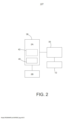
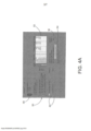
[0038] Para um melhor entendimento do presente Pedido de Patente de Invenção, referências serão feitas agora, apenas a título de exemplo, com relação aos desenhos anexos, no qual: A figura 1 é uma visualização lateral esquemática de um equipamento de perfuração utilizando um método de acordo com o presente Pedido de Patente de Invenção; A figura 2 é um diagrama de bloco esquemático de um PLC, compreendendo um controlador de velocidade de acordo com o presente Pedido de Patente de Invenção; A figura 3 é um gráfico de frequência versus coeficiente de reflexão, mostrando uma comparação entre um mecanismo de perfuração que utiliza um controlador de velocidade de acordo com o presente Pedido de Patente de Invenção e um controlador de velocidade padrão; A figura 4A é uma imagem da primeira tela disponível no console do perfurador para configuração e controle do método de acordo com o presente Pedido de Patente de Invenção; A figura 4B é uma imagem da segunda tela disponível no console do perfurador que ilustra o torque do “drive” em tempo real e uma estimativa da velocidade de rotação de perfuração da estrutura inferior do poço na Fig. 1; As figuras 5 e 6 são gráficos ilustrando os resultados de uma simulação computacional delineando um método de acordo com o presente Pedido de Patente de Invenção; e As figuras 7 e 8 são gráficos ilustrando os resultados de um teste de um método de acordo com o presente Pedido de Patente de Invenção.[0038] For a better understanding of this Patent Application, references will now be made, just by way of example, with respect to the attached drawings, in which: Figure 1 is a schematic side view of a drilling rig using a method according to the present patent application; figure 2 is a schematic block diagram of a PLC, comprising a speed controller according to the present patent application; Figure 3 is a graph of frequency versus reflection coefficient, showing a comparison between a drilling mechanism using a speed controller according to the present patent application and a standard speed controller; Figure 4A is an image of the first screen available on the driller's console for configuring and controlling the method in accordance with the present Patent Application; Figure 4B is an image of the second screen available on the driller's console that illustrates the drive torque in real time and an estimate of the drilling rotational speed of the lower structure of the well in Fig. 1; Figures 5 and 6 are graphs illustrating the results of a computational simulation outlining a method according to the present Patent Application; and Figures 7 and 8 are graphs illustrating the results of a test of a method according to the present Patent Application.
[0039] Com relação à Figura 1, um equipamento de perfuração 10 controla uma operação de perfuração utilizando uma coluna de perfuração 12 que compreende extensões de tubulações de perfuração 14 aparafusadas em conjunto de ponta a ponta. O equipamento de perfuração 10 pode ser qualquer tipo de equipamento de perfuração petrolífero, de mineração, geotérmico ou utilitário, incluindo: plataformas flutuantes e plataformas de terra, plataformas móveis e de inclinação, plataformas submersíveis e semi-submersíveis, navios de perfuração e plataforma auto-elevatória. Uma coluna de perfuração típica possui uma extensão entre 0 e 5 km e possui em sua parte mais baixa uma quantidade de anéis de perfuração ou tubulação de perfuração pesada (HWDP). Os anéis de perfuração têm espessura mais grossa do que a tubulação de perfuração, a fim de resistir ao empenamento sob as forças de compressão: a tubulação de perfuração pode ter um diâmetro externo de 127 mm e uma espessura de parede de 9 mm, enquanto que um anel de perfuração pode ter um diâmetro externo de 10 até 250 mm e uma espessura de parede de 85 mm, por exemplo.[0039] Referring to Figure 1, a
[0040] Uma estrutura inferior do poço (BHA = bottom hole assembly) 16 é posicionada na extremidade inferior de uma coluna de perfuração 12. Uma BHA típica compreende um transmissor MWD 18 (que pode ser, por exemplo, um sistema de telemetria com fio, um sistema de telemetria por pulso de perfuração (NT: mud pulse telemetry system = técnica de envio de dados de perfuração codificados através de pulsos de pressão crescentes e decrescentes), um sistema de telemetria eletromagnético, um sistema de telemetria acústico ou um sistema de telemetria de tubulação com cabo), centralizadores 20, uma ferramenta direcional 22 (que pode ser uma sonda ou um anel montado), estabilizadores (fixos ou variáveis) e uma broca de perfuração 28, que em uso é girada por um “top drive” através de uma coluna de perfuração 12.[0040] A bottom hole assembly (BHA) 16 is positioned at the lower end of a
[0041] O equipamento de perfuração compreende um mecanismo de perfuração 30. A função do mecanismo de perfuração 30 é girar a coluna de perfuração 12 e, por meio dela, a perfuração 28 na extremidade inferior. Atualmente, a maior parte dos equipamentos de perfuração utiliza “top drives” para girar a coluna de perfuração 12 e a broca 28 para realizar a perfuração. No entanto, alguns equipamentos de perfuração utilizam uma mesa rotativa e o presente Pedido de Patente de Invenção é igualmente aplicável para tais equipamentos. O presente Pedido de Patente de Invenção é também igualmente útil em perfurações de qualquer tipo de poço, p. ex., reto, fora de padrão, horizontal e vertical.[0041] The drilling rig comprises a
[0042] Uma bomba 32 é colocada na superfície e, em uso, bombeia o fluido da perfuração através da coluna de perfuração 12 e através da broca de perfuração 28 e serve para resfriar e lubrificar a broca durante a perfuração e para devolver o cascalho para a superfície no espaço anular formado entre a coluna de perfuração e o poço (não mostrado).[0042] A
[0043] As informações e dados de perfuração são exibidos no console do perfurador 34 que compreende uma tela sensível ao toque 36 e um aparelho de controle do usuário, p.ex., um teclado (não mostrado) para controlar, pelo menos, parte do processo de perfuração. Um PLC digital 38 envia para e recebe dados do console 34 e do “top drive”. Em particular, o perfurador é capaz de definir um comando de velocidade e um limite de torque para o “top drive” controlar a velocidade na qual a broca de perfuração 28 gira.[0043] The drilling information and data are displayed on the
[0044] Com relação à Figura 2, o PLC 38 compreende uma memória flash não-volátil 40 (ou 5 outras memórias, tais como um RAM apoiado por bateria). A memória armazena instruções executáveis que, quanto executadas, realizam a função de um controlador de velocidade 42 para o “top drive”. O controlador de velocidade 42 compreende um controlador PI com anti-finalização que funciona conforme descrito em maiores detalhes logo abaixo. Nesta aplicação, o controlador de velocidade 42 é separado e distinto com relação ao “top drive”. No entanto, é possível fornecer a funcionalidade do controlador de velocidade, conforme descrito aqui, como parte de um controlador de velocidade integrado e exclusivo de um “top drive”. Tal funcionalidade integrada pode ser fornecida ou no momento da fabricação ou pode ser parte de uma atualização de software realizada em um “top drive”, quer dentro ou fora do local. Em outras aplicações, o PLC pode ser um PLC análogo.[0044] Referring to Figure 2, the
[0045] A coluna de perfuração 12 pode ser considerada como uma linha de transmissão de ondas torcionais. Uma variação do torque de fricção na broca de perfuração 28 ou em qualquer outro lugar ao longo da coluna gera uma onda torcional que se propaga para cima e é particularmente refletida em descontinuidades geométricas. Quando a onda transmitida alcança o “top drive”, ela é parcialmente refletida para a coluna de perfuração 12. Para um “top drive” com um controlador de velocidade rígido e/ou de inércia alta a reflexão é quase total, de modo que apenas uma pequena quantidade de energia é absorvida pelo “top[0045] The
[0046] Para quantificar o amortecimento induzido pelo “top drive”, um coeficiente de reflexão complexo r para ondas torcionais na interface “top drive” / coluna de perfuração pode ser definido conforme segue: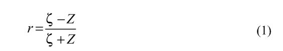
[0047] Uma representação complexa da impedância de um “top drive” pode ser determinada conforme segue. Se a anti-finalização do controlador de velocidade é negligenciada (a qual é uma função não-linear que limita o torque) o torque do “drive” do “top drive” pode ser escrito como:
[0048] Desprezando as perdas de transmissão, a equação de movimento do eixo de saída do “top drive” é:
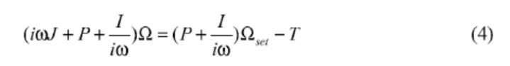
[0049] Para simplificar, os mesmos nomes das variáveis foram utilizados, como nas equações com base em tempo, embora Q, Qset e T representem agora amplitudes complexas. O fator de tempo implícito é exp(iwt ), onde


[0050] A taxa negativa - T / Q é chamada de impedância da extremidade superior Z da coluna:
[0051] Esta impedância pode ser facilmente generalizada para um controlador PID ideal, através da adição de um novo termo iwD a ele, onde D é o termo derivativo do controlador. Um termo-D positivo (normal) irá aumentar a inércia efetiva do “top drive”, enquanto um fator negativo irá reduzi-lo. Na prática, devido à diferenciação de tempo da velocidade medida ser um processo de direção de ruídos que melhora o ruído de alta frequência, o termo-D em um controlador PID é normalmente combinado com um filtro de passagem baixo. Este filtro introduz um eixo de fase que torna a impedância efetiva mais complicada e isso, portanto, aumenta o risco de criar instabilidades em algumas frequências, conforme exemplificado abaixo. Assim, embora o controlador PID com um termo-D possa ser utilizado para realizar o aspecto de ajuste do presente Pedido de Patente de Invenção, isso não é recomendado.[0051] This impedance can be easily generalized to an ideal PID controller, by adding a new term iwD to it, where D is the derivative term of the controller. A positive (normal) D-term will increase the effective top drive inertia, while a negative factor will decrease it. In practice, because measured velocity time differentiation is a noise steering process that improves high-frequency noise, the D-term in a PID controller is usually combined with a low-pass filter. This filter introduces a phase axis that makes the effective impedance more complicated and this, therefore, increases the risk of creating instabilities at some frequencies, as exemplified below. Thus, although a PID controller with a D-term can be used to accomplish the tuning aspect of the present application, this is not recommended.
[0052] Combinando as equações (1) e (6), tem-se a seguinte expressão para o coeficiente de reflexão, válido para “top drives” de velocidade controlada do tipo PI:
[0053] Sua magnitude tem uma igualdade mínima de:

[0054] Esta realização é significante visto que, como uma primeira etapa para alcançar um bom amortecimento, o termo-I do controlador PI é dependente apenas da frequência de oscilação da vibração torcional agarra e solta e da inércia efetiva do “top drive”. Uma vez que a inércia efetiva é rapidamente determinada, quer antes da operação ou a partir das figuras especificadas pelo fabricante, e visto que a frequência de oscilação da vibração torcional agarra e solta pode ser rapidamente determinada durante a perfuração, isso torna o ajuste do controlador PI objetivo, enquanto obtém uma boa absorção de energia pelo “top drive” das oscilações da vibração torcional agarra e solta.[0054] This realization is significant since, as a first step towards achieving good damping, the I-term of the PI controller is dependent only on the oscillation frequency of the torsional vibration grip and release and the effective inertia of the top drive. Since the effective inertia is quickly determined, either before operation or from the figures specified by the manufacturer, and since the oscillation frequency of the torsional vibration grip and release can be quickly determined during drilling, this makes controller adjustment PI objective, while getting good energy absorption by the “top drive” of the torsional vibration oscillations grab and go.
[0055] Esta primeira etapa de ajuste do controlador de velocidade é uma boa primeira etapa em direção a um amortecimento efetivo das oscilações da vibração torcional agarra e solta. No entanto, o amortecimento pode ser melhorado. Em particular, o termo-I não ajustado do controlador de velocidade ainda é bastante alto, isto é, P >> Z, mantendo o coeficiente de reflexão próximo a -1. Descobrimos que para obter um amortecimento suficiente das oscilações da vibração torcional agarra e solta, o termo-P do controlador de velocidade deve ser diminuído, de modo que seja da mesma ordem de magnitude da impedância característica Z. No entanto, também descobrimos que não é desejável que o coeficiente de reflexão desapareça completamente, porque isso mudaria radicalmente a dinâmica da coluna de perfuração 12 e o modo do pêndulo se dividiria em dois novos modos, cada um com uma frequência diferente. Além disso, um controlador de velocidade extremamente suave que absorvesse quase toda a energia das ondas incidentes criaria flutuações de velocidade muito altas no “top drive”, em resposta às variações de torque da perfuração. Isso pode reduzir a eficiência da perfuração.[0055] This first step of tuning the speed controller is a good first step towards effective damping of the torsional vibration oscillations grab and go. However, damping can be improved. In particular, the unadjusted I-term of the speed controller is still quite high, that is, P >> Z, keeping the reflection coefficient close to -1. We have found that to obtain sufficient damping of the torsional vibration oscillations grasp and release, the P-term of the speed controller must be decreased so that it is of the same order of magnitude as the characteristic impedance Z. However, we have also found that it is not It is desirable that the reflection coefficient disappear completely, because this would radically change the dynamics of the
[0056] Descobrimos que o termo-P pode ser selecionado como um múltiplo não inteiro da impedância característica Z da coluna de perfuração, o qual pode ser expresso como P = Z / a, onde a é um fator de mobilidade normalizado (adimensional) menor que a unidade que é ajustável por computador ou pelo operador dentro de determinados limites, conforme descrito abaixo. Uma vez definido o termo-I para fazer a parte imaginária da equação (7) desaparecer, definir o termo-P conforme descrito faz com que o mínimo do coeficiente de reflexão (i.e., a absorção do pico de energia pelo “top drive”) na frequência de oscilação da vibração torcional agarra e solta ws, se torne:
[0057] Ao permitir o ajuste do fator de mobilidade a, a quantidade de energia refletida para a coluna de perfuração 12 pode ser controlada, dentro de limites. Estes limites podem ser definidos permitindo apenas uma determinada faixa de valores para a, tais como de 0,05 a 0,33. Isso corresponde a uma faixa de magnitude de rmin de cerca de 0,9 a 0,5. Acredita-se que esta faixa permite que o amortecimento seja controlado, de modo que as oscilações da vibração torcional agarra e solta possam ser inibidas. Se o controlador de velocidade 42 for muito mais rígido do que isso (i.e., com um coeficiente de reflexão maior que cerca de 0,9) percebemos que muito da energia torcional das oscilações de energia é refletida na coluna de perfuração (12). Além disso, se o controlador de velocidade (42) for muito suave (i.e., com um coeficiente de reflexão menor que cerca de 0,5) percebemos que o desempenho de perfuração (p.ex., em termos de ROP) pode ser afetado.[0057] By allowing the adjustment of the mobility factor a, the amount of energy reflected to the
[0058] Um controlador de velocidade padrão é projetado para manter a velocidade do motor constante e P e I reais constantes com relação ao eixo do moto. Um motor de “drive” típico com uma potência nominal de 900 kW e uma inércia de motor de Jm = 25kgm2 é tipicamente controlado por um controlador de velocidade do motor de Pm = 500 Nms. O fator-I do controlador de velocidade é mais comumente determinado de forma indireta, como o fator-P dividido por uma integração de tempo constante de normalmente €i = 0,3s. Como exemplo, considere uma direção com um motor conectado ao eixo de saída com uma transmissão tendo uma inércia de Jg = 250kgm2 e uma taxa de transmissão de ng = 5,32. A inércia de “drive” efetiva é, então, Jd = Jg + ng2 Jm = 960kgm2. Os fatores do controlador de velocidade efetivos relativos ao eixo de saída são semelhantemente P = ng2 Pm ~ 14000Nms e I = P / €i ~ 47000Nm. Em comparação, a impedância característica para uma tubulação de 5 polegadas com Z ~ 340 Nms é apenas 2,4% da parte real da impedância de “drive”.[0058] A standard speed controller is designed to keep the motor speed constant and real P and I constant with respect to the motor shaft. A typical drive motor with a rated power of 900 kW and a motor inertia of Jm = 25kgm2 is typically controlled by a motor speed controller of Pm = 500 Nms. The speed controller I-factor is most commonly determined indirectly, as the P-factor divided by a constant time integration of typically €i = 0.3s. As an example, consider a drive with a motor connected to the output shaft with a transmission having an inertia of Jg = 250kgm2 and a transmission ratio of ng = 5.32. The effective drive inertia is then Jd = Jg + ng2 Jm = 960kgm2. The effective speed controller factors relative to the output shaft are similarly P = ng2 Pm ~ 14000Nms and I = P / €i ~ 47000Nm. In comparison, the characteristic impedance for a 5-inch pipe with Z ~ 340 Nms is only 2.4% of the real part of the “drive” impedance.
[0059] A Figura 3 é um gráfico 48 de magnitude do coeficiente de reflexão |r| versus a frequência e mostra a diferença entre um controlador de velocidade rígida padrão (curva 50) e um controlador de velocidade ajustado de acordo com o presente Pedido de Patente de Invenção (curva 52). O último é calculado com um fator de mobilidade de a = 0,25 e um termo-I fornecendo amortecimento máximo a 0,2Hz (período de oscilação da vibração torcional agarra e solta de 5s). Nesta frequência, a reflexão é reduzida de cerca de 0,993 (controlador PI padrão) para 0,6 (controlador PI ajustado conforme acima), o que representa uma dramática melhoria no amortecimento pelo “top drive” na frequência de oscilação da vibração torcional agarra e solta.[0059] Figure 3 is a 48 magnitude graph of the reflection coefficient |r| versus frequency and shows the difference between a standard hard speed controller (curve 50) and a speed controller tuned according to the present patent application (curve 52). The latter is computed with a mobility factor of a = 0.25 and an I-term giving maximum damping at 0.2Hz (grab-and-release torsional vibration oscillation period of 5s). At this frequency, the reflection is reduced from about 0.993 (standard PI controller) to 0.6 (PI controller tuned as above), which represents a dramatic improvement in damping by the “top drive” at the oscillation frequency of the torsional vibration grip and drop.
[0060] Vale ressaltar o fato de que em ambos os casos, o coeficiente de reflexão permanece abaixo de 1, mas se aproxima desse limite uma vez que a frequência se aproxima quer de zero ou infinito. Por conseguinte, o controlador PI padrão nunca fornece um amortecimento negativo que possa de outro modo amplificar os componentes de vibração torcional. No entanto, o amortecimento é insatisfatório e distante da relativamente estreita banda de absorção a l-2Hz. Em contraste, o controlador PI ajustado fornece uma banda de absorção comparativamente ampla, com menos de 80% de reflexão entre cerca de 0,1Hz e 0,4Hz. Há, inclusive, um substancial efeito de amortecimento remanescente (|r|=0,965) a 0,6 Hz, que é três vezes a frequência de oscilação da vibração torcional agarra e solta e se aproxima da segunda frequência de ressonância da coluna de perfuração.[0060] It is worth mentioning the fact that in both cases, the reflection coefficient remains below 1, but approaches this limit as the frequency approaches either zero or infinity. Therefore, the standard PI controller never provides negative damping that might otherwise amplify torsional vibration components. However, the damping is poor and far from the relatively narrow absorption band at 1-2Hz. In contrast, the tuned PI controller provides a comparatively wide absorption band, with less than 80% reflection between about 0.1Hz and 0.4Hz. There is even a substantial damping effect remaining (|r|=0.965) at 0.6 Hz, which is three times the oscillation frequency of the torsional grip and release vibration and approaches the second resonant frequency of the drill string.
[0061] A inércia efetiva J do mecanismo de perfuração, a impedância característica Z e a frequência de oscilação da vibração torcional agarra e solta as alteram a largura de banda de absorção da curva de reflexão-frequência na Fig. 3. Em particular, a largura de banda de absorção é inversamente proporcional à taxa de a, J / Z- Para um mecanismo de perfuração com uma grande inércia efetiva e/ou uma tubulação de perfuração delgada, tornar esta taxa mais ampla (p.ex., maior que 5), faz com que a largura de banda de absorção diminua. Neste caso, torna-se mais importante assegurar que o período de oscilação da vibração torcional agarra e solta estimado seja determinado de forma mais precisa (se possível), de modo que a frequência de amortecimento máximo esteja tão próxima quanto possível da frequência de oscilação da vibração torcional agarra e solta real.[0061] The effective inertia J of the drilling mechanism, the characteristic impedance Z and the oscillation frequency of the torsional vibration grip and release change the absorption bandwidth of the reflection-frequency curve in Fig. 3. In particular, the absorption bandwidth is inversely proportional to the rate of a, J / Z- For a drilling mechanism with a large effective inertia and/or a thin drill pipe, make this rate wider (e.g. (e.g., greater than 5), causes the absorption bandwidth to decrease. In this case, it becomes more important to ensure that the estimated torsional vibration oscillation period is determined as precisely as possible (if possible), so that the maximum damping frequency is as close as possible to the oscillation frequency of the real torsional vibration grip and release.
[0062] A redução na magnitude do coeficiente de reflexão e no amortecimento positivo correspondente sobre toda a banda de frequência é muito importante e é alcançado somente com um controlador PI único. Isso está em contraste com outros métodos ativos que utilizam ciclos em série de realimentação em cascata com um controlador de velocidade padrão, ou que dependem de alguns parâmetros medidos, tais como torque de coluna ou “drive”, para fornecer um sinal de realimentação para p PLC. Os filtros utilizados nas funções de realimentação em cascata podem ser adequados para amortecer as oscilações da vibração torcional agarra e solta fundamentais, mas eles podem causar instabilidades e amortecimento negativo em frequências mais altas.[0062] The reduction in the magnitude of the reflection coefficient and the corresponding positive damping over the entire frequency band is very important and is achieved only with a single PI controller. This is in contrast to other active methods that use series cascaded feedback loops with a standard speed controller, or that rely on some measured parameter, such as column torque or drive, to provide a feedback signal to p PLC. Filters used in cascaded feedback functions may be adequate to dampen fundamental torsional vibration oscillations, but they can cause jitter and negative damping at higher frequencies.
[0063] Na prática, o termo-P para o controlador de velocidade ajustado pode ser determinado conforme segue:
[0064] Para determinar o termo-I na prática, há duas variáveis a serem avaliadas: (a) a frequência angular ws das oscilações da vibração torcional agarra e solta, e (b) a inércia efetiva J do “top drive”. A última é relativamente objetiva para esta determinação e pode tanto ser calculada a partir dos valores teóricos da inércia de transmissão, da taxa de transmissão e da inércia do rotor do motor, quanto pode ser encontrada experimentalmente realizando um teste de aceleração quando o “top drive” estiver desconectado da coluna. Uma formula típica para o cálculo da inércia do “top drive” é:
[0065] Há vários modos pelos quais a frequência angular ^ pode ser estimada, incluindo: (i) cálculos a partir da geometria da coluna, (ii) por medição manual (p.ex., utilizando um cronômetro) e (iii) por determinação automática no software PLC. Uma vantagem importante do aspecto de ajuste do PI o presente Pedido de Patente de Invenção é a de que o efeito de amortecimento das oscilações da vibração torcional agarra e solta ainda é obtido, mesmo se a estimativa do período de oscilação da vibração torcional agarra e solta utilizada para ajustar o controlador PI não for muito precisa. Por exemplo, a Fig. 3 mostra um amortecimento máximo ocorrendo a uma frequência de 0,2Hz. Mesmo se a frequência de oscilações da vibração torcional agarra e solta real for mais baixa ou mais alta que isso, ainda haverá um bom efeito de amortecimento (r ~ 0,8) obtido entre aproximadamente 0,09Hz e 0,4Hz. Consequentemente, os métodos utilizados para estimar o período de oscilação da vibração torcional agarra e solta não precisam ser particularmente precisos. (i) Geometria da Coluna[0065] There are several ways in which the angular frequency ^ can be estimated, including: (i) calculations from column geometry, (ii) by manual measurement (eg, using a stopwatch), and (iii) by automatic determination in the PLC software. An important advantage of the PI tuning aspect of the present patent application is that the damping effect of the torsional vibration oscillations grab and release is still obtained even if the oscillation period estimation of the torsional vibration grab and release used to adjust the PI controller is not very accurate. For example, Fig. 3 shows maximum damping occurring at a frequency of 0.2Hz. Even if the frequency of oscillations of the actual torsional grip and release vibration is lower or higher than this, there will still be a good damping effect (r ~ 0.8) obtained between approximately 0.09Hz and 0.4Hz. Consequently, the methods used to estimate the oscillation period of torsional vibration vibration do not need to be particularly accurate. (i) Column Geometry
[0066] É possível empregar uma abordagem teórica para determinar o período de oscilação da vibração torcional agarra e solta, utilizando parâmetros da coluna de perfuração disponíveis no local no livro de registro. Um livro de registro é compilado no local para cada coluna de perfuração e compreende um registro detalhado das propriedades de cada seção da coluna de perfuração (p.ex., OD, ID, tipo de tubulação), uma seção sendo definida como uma extensão (p.ex., 300m) do mesmo tipo de tubulação de perfuração.[0066] It is possible to employ a theoretical approach to determine the period of oscillation of the torsional vibration grip and release, using drill string parameters available locally in the log book. A log book is compiled on site for each drill string and comprises a detailed record of the properties of each drill string section (eg, OD, ID, pipe type), one section being defined as a length ( eg 300m) of the same type of drill pipe.
[0067] A seguir, assume-se que a coluna de perfuração 12 consiste de uma seção de tubulação de perfuração
[0068] Existem soluções não triviais para este sistema de equações, caso o determinante da desapareça, isto é, quando
[0069] Aqui, os coeficientes de reflexão no “drive” rd e na parte inferior da coluna de perfuração rb foram introduzidas conforme segue:
[0070] Observe que o coeficiente de reflexão rd≈ -1 do “top drive” para um controlador de velocidade rígido (|Zd| >> ζ ) e o coeficiente de reflexão rb da broca igualam a unidade para um extremidade inferior livre (Zb = 0).[0070] Note that the top drive reflection coefficient rd≈ -1 for a rigid speed controller (|Zd| >> ζ ) and the drill reflection coefficient rb equal unity for a free bottom end (Zb = 0).
[0071] As raízes da equação (12) podem ser escritas como: ilkl = ln(rdrft) = ln|rrfrj + /(/:2π + α,7 + αj (13) onde n é um inteiro não-negativo e αd e αb são as justificações (ângulos de fase) dos coeficientes de reflexão complexos rd e rb, respectivamente. As frequências de ressonância angular correspondentes são:
[0072] Uma vez que, em geral, as magnitudes e fases do coeficiente de reflexão são dependentes de frequência, a equação acima é transcendente, sem soluções analíticas explícitas. No entanto, isso pode ser resolvido numericamente por um PC ou outro computador.
[0073] O termo imaginário da equação supracitada representa o amortecimento dos eigenmodes (modos normais de vibração do sistema de oscilação). Se |rdrb| < 1, a parte imaginária da raiz é positiva, representando, dessa forma, um amortecimento positivo e normal e fazendo com que o fator de tempo exp(iwnt) diminua com o tempo. Em contrapartida, se |rdrb| > 1, o amortecimento se torna negativo, fazendo com que uma pequena amplitude cresça exponencialmente com o tempo.[0073] The imaginary term of the aforementioned equation represents the damping of the eigenmodes (normal modes of vibration of the oscillation system). If |rdrb| < 1, the imaginary part of the root is positive, thus representing positive, normal damping and causing the time factor exp(iwnt) to decrease with time. In contrast, if |rdrb| > 1, damping becomes negative, causing a small amplitude to grow exponentially with time.
[0074] Como exemplo, considere um caso com um controlador de velocidade completamente rígido (|rd| = -1 e αd = π) girando uma coluna de perfuração, compreendendo uma inércia finita da parte inferior do poço (Zb = ioJb, |rb| = 1 e αd = -2tan-1 (J / Z )). Então, a frequência mais baixa (oscilação da vibração torcional agarra e solta teórica) ws se torna:
[0075] Sem a inércia extra da estrutura inferior do poço, esta expressão se reduz a
[0076] Descobrimos que isso é útil para estudar a relação entre a amplitude de velocidade da extremidade inferior


[0077] Utilizando-se do fato de que a impedância característica pode ser escrita como

[0078] Observe que o segundo termo desaparece se o controlador de velocidade for muito rígido (r « -1) ou quando kl ~ n / 2. No entanto, se um controlador de velocidade suave for utilizado e houver uma inércia alta próxima à broca, de modo que kl para a frequência de oscilação da vibração torcional agarra e solta seja significativamente menor que n /2, então, o segundo termo pode ser significante e não deve ser omitido.[0078] Note that the second term disappears if the speed controller is too rigid (r « -1) or when kl ~ n / 2. However, if a soft speed controller is used and there is a high inertia close to the drill , so that kl for the oscillation frequency of the torsional vibration grip and release is significantly less than n /2, then the second term may be significant and should not be omitted.
[0079] A teoria supracitada pode ser generalizada para colunas com muitas seções e também para casos com amortecimento distribuído. Se um termo de amortecimento linear for incluído, a generalização faz com que os números de onda e as impedâncias características sejam complexos e não puramente reais. Se a coluna consiste de m seções uniformes, a solução de onda geral consiste de amplitudes de velocidade complexas 2m, representando pares de ondas de propagação para cima e para baixo. A continuidade da torção e velocidade angular através dos limites de seção pode ser expressa pelas condições de limitação interna 2(m -1), que contribuem para as duas condições finais na equação (11). As raízes deste sistema de equações são aquelas frequências que tornam a matriz do sistema singular. Embora seja possível encontrar uma expressão analítica para o determinante do sistema, as soluções são encontradas numericamente por um PC ou outro computador no local. A IADC/SPE 15564 fornece um exemplo de um modo de fazer isso, e seus conteúdos estão aqui incorporados por referência para todos os fins.[0079] The above theory can be generalized for columns with many sections and also for cases with distributed damping. If a linear damping term is included, the generalization makes the wavenumbers and characteristic impedances complex and not purely real. If the column consists of m uniform sections, the general wave solution consists of 2m complex velocity amplitudes, representing pairs of up- and down-propagating waves. The continuity of torsion and angular velocity across the section boundaries can be expressed by the internal constraint conditions 2(m -1), which contribute to the final two conditions in equation (11). The roots of this system of equations are those frequencies that make the matrix of the system singular. While it is possible to find an analytic expression for the system determinant, solutions are found numerically by a PC or other computer on site. IADC/SPE 15564 provides an example of one way to do this, and its contents are incorporated herein by reference for all purposes.
[0080] A Figura 4 mostra uma tela típica 50 disponível no console do perfurador que permite ao perfurador acionar um PC para estimar um novo período de oscilação da vibração torcional agarra e solta com base na geometria da coluna. Em particular, uma tabela 52 representa as seções da coluna de perfuração, incluindo BHA, tubulação de perfuração pesada (HWDP) e as seções de tubulação de perfuração 1 a 6. Os campos disponíveis para cada seção são: extensão, diâmetro externo e diâmetro interno. O perfurador primeiramente determina, a partir do livro de registro local, em quantas seções a coluna de perfuração está dividida. Neste exemplo, a coluna de perfuração possui oito seções. Para cada seção, o perfurador insere valores nos três campos. Um botão 54 permite que o perfurador acione um novo período de oscilação da vibração torcional agarra e solta a ser estimado com base na geometria da coluna inserida na tabela 52. Em particular, a tabela estabelece a equação matriz de 2mx2m, acima mencionada, e o PL (não mostrado) utiliza um método numérico para encontras as raízes da matriz que tornam a matriz singular. A menor raiz é o resultado 56 do período de oscilação da vibração torcional agarra e solta na tela 50. (ii) Estimativa Manual[0080] Figure 4 shows a
[0081] Para determinar o período de oscilação da vibração torcional agarra e solta manualmente, o perfurador pode observar o torque do “drive” conforme mostrado no console do perfurador 34 e determinar o período medindo o período de variação do torque de “drive” com um cronômetro. Isso é rapidamente feito, uma vez que cada período tem normalmente de 2s a 10s. Um método alternativo é que o perfurador ouça a mudança de intensidade no motor do “top drive” e determine o tempo do período deste modo. Conforme acima mencionado, tais métodos devem ser suficientes uma vez que a frequência de oscilação da vibração torcional agarra e solta estimada não tenha de estar particularmente próxima à frequência de oscilação da vibração torcional agarra e solta real, a fim de que as oscilações da vibração torcional agarra e solta sejam amortecidas. (iii) Estimativa Automática[0081] To determine the period of oscillation of the torsional vibration manually grab and release, the driller can observe the torque of the "drive" as shown on the console of the
[0082] Estimativa automática significa que o software PLC estima o período ou frequência de oscilação da vibração torcional agarra e solta a partir de medições feitas durante a perfuração. Em particular, o sinal de torque do “top drive” é filtrado por um filtro de passagem de banda que transmite frequências na faixa de 0,1Hz a 0,5Hz (i.e. um período entre 2s e 10s), isto é, o filtro favorece o componente de oscilação da vibração torcional agarra e solta e suprime todos os outros componentes de frequência. O PLC, então, detecta o período entre cada novo zero até a passagem do sinal de torque filtrado e utiliza estes valores em um filtro de suavização recursivo para obter uma estimativa de período precisa e estável. O filtro de suavização final é congelado quando a gravidade da oscilação da vibração torcional agarra e solta (vide abaixo) cai abaixo de um valor crítico baixo ou quando o método de ajuste é ativado.[0082] Automatic estimation means that the PLC software estimates the period or frequency of oscillation of the torsional vibration grip and release from measurements taken during drilling. In particular, the top drive torque signal is filtered by a bandpass filter that transmits frequencies in the range of 0.1Hz to 0.5Hz (i.e. a period between 2s and 10s), i.e. the filter favors the oscillation component of torsional vibration grabs and lets go and suppresses all other frequency components. The PLC then detects the period between each new zero until the filtered torque signal passes and uses these values in a recursive smoothing filter to obtain an accurate and stable period estimate. The final smoothing filter is frozen when the severity of the torsional vibration oscillation grip and release (see below) drops below a low critical value or when the tuning method is activated.
[0083] Para ajudar o estimador de período a rapidamente encontrar o período preciso, o operador pode ou colocar um valor de início real ou pegar um valor teórico calculado a partir da coluna atual (determinado conforme a seção Geometria da Coluna acima).[0083] To help the period estimator quickly find the precise period, the operator can either enter an actual start value or take a theoretical value calculated from the current column (determined per the Column Geometry section above).
[0084] Em uso, o controlador PI ajustado é ativado quando há uma movimentação de oscilação da vibração torcional agarra e solta significante (conforme determinado pelo perfurador ou pelo software). No entanto, a estimativa de frequência da oscilação da vibração torcional agarra e solta (medição de período) acontece antes que o controlador PI ajustado seja realmente utilizado para controlar o mecanismo de perfuração. Uma vez completo, o estimador de período é desligado quando o controlador PI está ligado, por que o período natural das oscilações da vibração torcional agarra e solta pode mudar ligeiramente quando o controle de velocidade suave é utilizado.[0084] In use, the adjusted PI controller is activated when there is a significant torsional vibration oscillation movement grab and release (as determined by the driller or software). However, the frequency estimation of the torsional vibration oscillation (period measurement) happens before the adjusted PI controller is actually used to control the drilling mechanism. Once complete, the period estimator is turned off when the PI controller is on, because the natural period of torsional vibration oscillations and releases can change slightly when smooth speed control is used.
[0085] Parece não haver a necessidade de reajuste muito frequente da frequência estimada, porque a frequência de oscilação da vibração torcional agarra e solta natural varia ligeiramente com a extensão da coluna de perfuração. É uma boa ideia, no entanto, atualizar automaticamente o período a cada conexão, isto é, quando outros 30 m de tubulações de perfuração forem adicionados à coluna de perfuração. Para tanto, é possível utilizar analises de sensibilidade teórica para prever como o período de oscilação da vibração torcional agarra e solta aumenta com a extensão da coluna de perfuração. Uma maneira de fazer isso (mas não a única maneira) é encontrar os períodos teóricos para duas extensões de colunas (L e L+200 m, por exemplo) e, em seguida, utilizar interpolação para o aumento causado pela adição de uma seção de 30 m, a fim de atualizar o período estimado.[0085] There seems to be no need for very frequent readjustment of the estimated frequency, because the oscillation frequency of the natural torsional vibration vibration varies slightly with the length of the drill string. It is a good idea, however, to automatically update the period on every connection, ie when another 30 m of drill pipe is added to the drill string. For this, it is possible to use theoretical sensitivity analyzes to predict how the period of oscillation of torsional vibration increases with the length of the drill string. One way to do this (but not the only way) is to find the theoretical periods for two column lengths (L and L+200 m, for example) and then use interpolation for the increase caused by adding a column length. 30 m in order to update the estimated period.
[0086] Estimativa da Gravidade da oscilação da vibração torcional agarra e solta e da Velocidade Instantânea da Broca[0086] Estimation of the Severity of the oscillation of the torsional vibration grip and release and the Instantaneous Speed of the Drill
[0087] Um aspecto adicional do presente Pedido de Patente de Invenção é fornecido como um conjunto de instruções executáveis no software PLC que permite a quantificação das variações de velocidade da broca e uma estimativa da velocidade de rotação instantânea da broca. ‘Velocidade da broca’ significa a velocidade de rotação da BHA, excluindo a contribuição do motor de perfuração opcional. Este aspecto do presente Pedido de Patente de Invenção pode ser fornecido separadamente ou em combinação com o aspecto de ajuste do controlador PI do presente Pedido de Patente de Invenção.[0087] An additional aspect of this Patent Application is provided as a set of executable instructions in PLC software that allows the quantification of variations in drill speed and an estimate of the instantaneous rotation speed of the drill. 'Drill speed' means the speed of rotation of the BHA, excluding the contribution of the optional drill motor. This aspect of the present application may be provided separately or in combination with the PI controller tuning aspect of the present application.
[0088] Esta estimativa é obtida através da combinação da conformidade torcional conhecida C da coluna de perfuração e das variações do torque de “drive”. Em geral, uma vez que o torque não é um sinal rigorosamente periódico, mas na maioria das vezes possui uma vasta gama de frequências, um cálculo preciso é extremamente complicado e não é, portanto, adequado para implementação em um PLC. No entanto, percebemos que uma vez que a movimentação de oscilações da vibração torcional agarra e solta é dominada por uma frequência de oscilações da vibração torcional agarra e solta fundamental, é possível obter estimativas razoavelmente boas com base apenas nestas frequências.[0088] This estimate is obtained by combining the known torsional compliance C of the drill string and the variations of the "drive" torque. In general, since torque is not a strictly periodic signal but most often has a wide range of frequencies, an accurate calculation is extremely complicated and is therefore not suitable for implementation in a PLC. However, we noticed that since the movement of torsional vibration oscillations grasp and release is dominated by a frequency of torsional vibration oscillations of fundamental torsional vibration and release, it is possible to obtain reasonably good estimates based on these frequencies alone.
[0089] A equação principal é a (17) acima, que descreve uma boa aproximação para a amplitude de velocidade complexa em função do torque da coluna superior. Os dois termos nesta expressão devem ser tratados de forma diferente, porque eles representam componentes harmônicos compreendendo uma diferença de fase de 90 graus. Enquanto o fator imaginário iaT, deve ser tratado como o derivativo de tempo do torque filtrado por passagem de banda, o fator de termo real aTs pode ser aproximado como o produto do torque filtrado por passagem de banda e pela frequência de oscilação da vibração torcional agarra e solta. Uma vez que o filtro de passagem de banda suprima todas as frequências exceto a frequência de oscilação da vibração torcional agarra e solta, é possível substituir a integração de tempo direta pela aproximação com base na integração. Esta aproximação tem como base o fato de que ia ~ -as2 / (ia), onde 1 / (ia) representa a integração de tempo. Esta aproximação favorece a frequência de oscilação da vibração torcional agarra e solta e suprime os harmônicos mais altos. As versões de divisão de tempo de (17), adequadas para a implementação no PLC 38 são: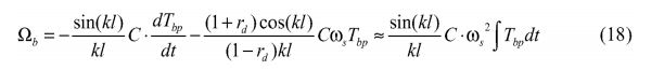
[0090] Aqui, o parâmetro de fase é kl = wsl /c. Na última aproximação, a aproximação integral para a derivação de tempo é utilizada e o segundo termo é omitido.[0090] Here, the phase parameter is kl = wsl /c. In the last approximation, the integral approximation for the time derivation is used and the second term is omitted.
[0091] Embora a fórmula acima tenha como base uma coluna de seção única, simulações demonstraram que ela também fornece boas estimativas para colunas de multisseções, se a conformidade C total da coluna for utilizada: ml
[0092] Uma versão do algoritmo implementado no PLC (38), para estimar tanto a velocidade instantânea da BHA quanto a gravidade das oscilações da vibração torcional agarra e solta, compreende as seguintes etapas: 1. Estimar o torque da coluna através da correção dos efeitos de inércia (subtrair a inércia efetiva do motor vezes a aceleração angular) e através da utilização da taxa de transmissão para escalá-la corretamente; 2. Filtrar a passagem de banda do torque estimado, com o filtro de passagem de banda centralizado na frequência de oscilação da vibração torcional agarra e solta estimada/observada. O filtro deve ser de 2a ordem ou superior, mas pode ser preferivelmente implementado no PLC como uma série de filtros IIR recursivos de 1a ordem; 3. Calcular a conformidade estática total da coluna de perfuração utilizando a equação (19) acima referida; 4. Calcular o parâmetro de fase kl = wsl /c, onde ws é a frequência de oscilação da vibração torcional agarra e solta angular determinada; 5. Calcular a velocidade de perfuração dinâmica utilizando ou a versão precisa ou aproximada da equação (18) acima referida; 6. Calcular a “gravidade de oscilação da vibração torcional agarra e solta” a, que é a amplitude de oscilação da vibração torcional agarra e solta normalizada, determinada como a taxa de amplitude da velocidade de perfuração dinâmica sobre a velocidade rotacional média do “top drive”; 7. Encontrar a velocidade instantânea como a soma da velocidade do “top drive” filtrada por passagem baixa e a velocidade de perfuração dinâmica estimada. Reduzir a zero se a velocidade estimada se tornar negativa; 8. Esquematizar os dados resultantes em um gráfico (p.ex., RPM versus tempo); 9. Repetir as etapas 1 a 8 para fornecer uma estimativa de tempo real substancial da velocidade da broca.[0092] A version of the algorithm implemented in the PLC (38), to estimate both the instantaneous speed of the BHA and the severity of the oscillations of the torsional vibration grip and release, comprises the following steps: 1. Estimate the column torque through the correction of the inertia effects (subtract the effective motor inertia times the angular acceleration) and by using the transmission rate to scale it correctly; 2. Filter the estimated torque bandpass, with the bandpass filter centered on the oscillation frequency of the estimated/observed torsional grasp and release vibration. The filter must be 2nd order or higher, but can preferably be implemented in the PLC as a series of 1st order recursive IIR filters; 3. Calculate the total static compliance of the drill string using equation (19) above; 4. Calculate the phase parameter kl = wsl /c, where ws is the oscillation frequency of the determined angular torsional vibration; 5. Calculate the dynamic drilling speed using either the accurate or approximate version of equation (18) above; 6. Calculate the “grab and release torsional vibration oscillation gravity” a, which is the normalized torsional vibration amplitude of oscillation, determined as the ratio of amplitude of dynamic drilling velocity to the average rotational velocity of the “top”. drive"; 7. Find the instantaneous velocity as the sum of the low pass filtered top drive velocity and the estimated dynamic drilling velocity. Reduce to zero if estimated speed becomes negative; 8. Lay out the resulting data on a graph (eg, RPM versus time); 9. Repeat steps 1 through 8 to provide a substantial real-time estimate of drill speed.
[0093] Prevê-se que este método pode ser realizado apenas onde a estimativa de velocidade da BHA é resultante ou apenas onde a gravidade de oscilação da vibração torcional agarra e solta é resultante.[0093] It is anticipated that this method can be performed only where BHA velocity estimation is resultant or only where torsional vibration oscillation gravity grasp and release is resultant.
[0094] Com relação à etapa 6, uma forma possível de estimar a gravidade de oscilação da vibração torcional agarra e solta é utilizar a seguinte fórmula, onde LP() denota a filtragem de passagem baixa:
[0095] Como o método acima referido leva em consideração o coeficiente de reflexão, ele se aplica para ambos os controles de velocidade, padrão e ajustado. Durante os transientes de aceleração, quando a velocidade do “top drive” é significativamente alterada, o estimador não é confiável, uma vez que pode produzir grandes erros. Não obstante, acreditamos que esta é uma ferramenta útil para avaliar as condições de perfuração, quer automaticamente no software, quer através do mostrador para análise por um perfurador.[0095] As the above method takes into account the reflection coefficient, it applies to both standard and adjusted speed control. During acceleration transients, when the top drive speed is significantly changed, the estimator is unreliable as it can produce large errors. Nevertheless, we believe this is a useful tool for assessing drilling conditions, either automatically in the software or through the display for analysis by a driller.
[0096] A taxa de amplitude da velocidade dinâmica em relação à velocidade média do “top drive” é uma medição direta e quantitativa da movimentação de oscilação da vibração torcional agarra e solta, mais adequada que o torque dinâmico ou a amplitude de torque relativa. Mesmo que a velocidade estimada da broca não seja altamente precisa, ela fornece uma entrada valiosa para que o perfurador monitore isso em um gráfico de tendências que dará ao operador informações mais explicitas sobre o que está acontecendo com a broca. Interface do Usuário[0096] The dynamic velocity amplitude ratio in relation to the average speed of the top drive is a direct and quantitative measurement of the oscillation movement of the torsional vibration grip and release, more suitable than the dynamic torque or the relative torque amplitude. Even though the estimated bit speed is not highly accurate, it does provide valuable input for the driller to monitor this in a trend graph that will give the operator more explicit information about what is happening with the bit. User Interface
[0097] Uma interface de usuário é fornecida para um console do perfurador 34 que compreende uma interface gráfica (vide Figs. 4A e 4B) que provê o operador com informações diretas sobre o status da oscilação da vibração torcional agarra e solta. A oscilação da vibração torcional agarra e solta é indicada por três diferentes indicadores: • Um indicador de “luz de tráfego” 58 na Fig 4A com 3 níveis de oscilação da vibração torcional agarra e solta: uma luz verde para pequenas amplitudes (0-30%), uma luz de advertência amarela, se as oscilações de velocidade forem significantes (30-70%) e, finalmente, uma luz vermelha, se amplitudes ainda maiores forem estimadas. Este valor de porcentagem tem por base a gravidade da oscilação da vibração torcional agarra e solta, conforme anteriormente determinado. • A gravidade da oscilação da vibração torcional agarra e solta é esquematizada em um gráfico 62 de torque versus tempo na Fig. 4B para observar como a oscilação da vibração torcional agarra e solta se desenvolveu em um período de tempo especificado. • A velocidade instantânea da broca, estimada em um gráfico 64 de velocidade instantânea da broca versus tempo na Fig. 4B, fornece uma impressão direta e visual do status das oscilações da vibração torcional agarra e solta da perfuração.[0097] A user interface is provided for a console of the
[0098] Conforme mencionado acima, a tela 50 requer que o operador insira uma descrição aproximada da coluna, em termos de um registro simplificado. Este registro aceita até 8 seções diferentes, onde a extensão, o diâmetro interno e a massa por unidade de extensão são especificadas. Estas informações são utilizadas para calcular tanto a frequência teórica estimada para o modo mais baixo como a conformidade estática da coluna de perfuração nesta frequência.[0098] As mentioned above,
[0099] O operador pode deixar o controlador PI ajustado ligado ou desligado. No modo desligado, o controlador de velocidade do “drive” padrão é utilizado. Quando o ajuste está ativado, este controlador de velocidade é extrapolado pelo controlador PI ajustado 42, que é implementado no PLC 38. Se o controlador do “drive” no “top drive” é um modelo digital moderno, também é possível alterar o próprio controlador de velocidade do “drive”, ao invés de extrapolá-lo. No entanto, se o método de extrapolação for escolhido, isso é obtido enviando um comando de alta velocidade do PLC 38 para o controlador de velocidade no “top drive” e controlando dinamicamente o limite de torque de saída. Em perfurações normais, este limite de torque é utilizado como um limite de segurança para prevenir danos à coluna, se a coluna subitamente travar. No modo de controle ajustado, quando o PLC 38 controla dinamicamente o limite de torque, este limite é substituído por um limite de software correspondente no PLC 38.[0099] The operator can leave the PI controller set on or off. In off mode, the default “drive” speed controller is used. When the tuning is activated, this speed controller is extrapolated by the adjusted
[00100] O operador também pode alterar o fator de prevenção ou mobilidade a dentro de limites preestabelecidos através de botões 60 tipicamente entre 0,05 e 0,33. Um fator alto implica um controle de velocidade mais suave e menor probabilidade de a movimentação de oscilação da vibração torcional agarra e solta começar ou persistir. A desvantagem de um fator alto é uma flutuação maior da velocidade do “top drive” em resposta às alterações inofensivas no nível de torque da coluna. Pode ser necessário escolher um fator alto para reparar oscilações da vibração torcional agarra e solta graves, mas o operador pode reduzir o fator quando a perfuração suave for restaurada.[00100] The operator can also change the avoidance or mobility factor a within preset limits through
[00101] Prevê-se que a decisão de ativar e desativar o controlador de velocidade ajustado pode ser tomada pelo PLC (38) ou por outro controlador eletrônico. Tal controlador pode monitorar a estimativa instantânea da velocidade da broca, conforme estabelecido acima. Quando um padrão de período de oscilação da vibração torcional agarra e solta for observado, o controlador pode ativar o ajuste. Além disso, o controlador pode aumentar gradualmente o fator de mobilidade ou prevenção para aumentar a suavidade do “top drive”, se as oscilações da vibração torcional agarra e solta não forem reduzidas em magnitude dentro de um período predeterminado, p.ex., 2 minutos. Uma vez que as oscilações da vibração torcional agarra e solta tenham sido reduzidas ou tenham substancialmente desaparecido, o controlador pode reduzir gradualmente o fator de mobilidade ou prevenção (p.ex., reduzir para a = 0,1) para melhorar a eficiência da perfuração. Teste HIL (Hardware-in-the-Loop)[00101] It is expected that the decision to activate and deactivate the adjusted speed controller can be taken by the PLC (38) or by another electronic controller. Such a controller may monitor the instantaneous estimate of drill speed as set forth above. When an oscillation period pattern of torsional vibration grip and release is observed, the controller can activate the tuning. In addition, the controller can gradually increase the mobility or avoidance factor to increase the smoothness of the “top drive”, if the torsional vibration oscillations grab and release are not reduced in magnitude within a predetermined period, eg 2 minutes. Once the torsional grip and release vibration oscillations have been reduced or substantially disappeared, the controller can gradually reduce the mobility or avoidance factor (eg, reduce to a = 0.1) to improve drilling efficiency . HIL test (Hardware-in-the-Loop)
[00102] Recentemente, o método de ajuste PI foi testado extensivamente nas assim chamadas simulações de Hardware In the Loop (HIL). Nestes testes, os programas PLC são executados em um PLC físico conectado por meio de interface ao modelo de simulação de tempo real de um “drive” e de uma coluna de perfuração.[00102] Recently, the PI adjustment method has been extensively tested in so-called Hardware In the Loop (HIL) simulations. In these tests, the PLC programs are executed on a physical PLC connected through an interface to the real-time simulation model of a drive and a drill string.
[00103] O modelo de simulação a ser utilizado para o teste HIL do método de ajuste possui as seguintes características: 1. O “drive” é modelado como um controlador de velocidade PI padrão, com torque e limitações de potência e anti- finalização. O torque ou controlador atual é perfeito no sentido de que o torque atual é considerado para ser compatível com o torque estabelecido sem nenhum atraso. 2. O modelo pode lidar com uma pluralidade de motores de “drive” conectados ao eixo de saída por uma engrenagem. 3. A coluna de perfuração é modelada como uma série de elementos de molas e inércia agrupadas, provenientes de qualquer livro de registro. A extensão de grade utilizada na maioria dos exemplos abaixo é de aproximadamente 28 m, que é a extensão típica de uma plataforma tripla. Assim, os 3200m de extensão da coluna utilizados abaixo consistem de 114 elementos. 4. O torque de fricção estática é calculado para cada elemento com base na força de contato teórica, sendo uma função de peso e inclinação, curvatura e tensão. O efeito de WOB e do torque da broca também são incluídos. 5. O torque de fricção dinâmico dependente de velocidade é modelado como uma soma de três termos. O primeiro termo é uma variante de sinal suave da fricção da Coluna, o segundo representa uma fricção estática extra de início e o terceiro é um termo de amortecimento linear independente da força de contato. Para simular a instabilidade com a amplitude de oscilação crescente da perfuração suave, este coeficiente de amortecimento deve ser negativo.[00103] The simulation model to be used for the HIL test of the adjustment method has the following characteristics: 1. The “drive” is modeled as a standard PI speed controller, with torque and power limitations and anti-finish. The torque or current controller is perfect in the sense that the current torque is considered to match the set torque without any delay. 2. The model can handle a plurality of drive motors connected to the output shaft by a gear. 3. The drill string is modeled as a series of clustered spring and inertia elements taken from any log book. The grid length used in most of the examples below is approximately 28 m, which is the typical length of a triple deck. Thus, the 3200m long column used below consists of 114 elements. 4. Static friction torque is calculated for each element based on theoretical contact force, being a function of weight and tilt, bending and tension. WOB effect and drill torque are also included. 5. Speed-dependent dynamic frictional torque is modeled as a sum of three terms. The first term is a smooth sign variant of Column friction, the second represents extra static friction at start-up, and the third is a linear damping term independent of the contact force. To simulate instability with increasing oscillation amplitude of smooth drilling, this damping coefficient must be negative.
[00104] O modelo foi primeiramente desenvolvido como um modelo Simulink no ambiente Matlab. Ele foi posteriormente implementado com a caixa de ferramentas Simulation Module (Módulo de Simulação) no ambiente National Instrument Lab View e executado em uma poderosa plataforma de PC. Embora este PC não se utilize de um sistema operacional em tempo real (TR), sua alta potência torna o modelo TR válido para todos os fins práticos.[00104] The model was first developed as a Simulink model in the Matlab environment. It was later implemented with the Simulation Module toolbox in the National Instrument Lab View environment and run on a powerful PC platform. Although this PC does not use a real-time (TR) operating system, its high power makes the TR model valid for all practical purposes.
[00105] O programa de simulação Lab View é conectado ao PLC, ao assim chamado cartão SimbaPro PCI profibus DP (DP = Distributed Peripherals/Periféricos Distribuídos), que pode simular todos os nós dos DP’s conectados ao PLC. O tempo de atualização é estabelecido em 10ms (100Hz), que está dentro do ciclo de tempo do PLC (tipicamente de 20ms).[00105] The Lab View simulation program is connected to the PLC, to the so-called SimbaPro PCI profibus DP card (DP = Distributed Peripherals/Distributed Peripherals), which can simulate all DP nodes connected to the PLC. The update time is set to 10ms (100Hz), which is within the PLC cycle time (typically 20ms).
[00106] Os resultados do teste HIL são mostrados na Figura 5. A coluna utilizada é uma coluna de 3200m de extensão, similar à coluna utilizada no campo de teste (vide abaixo). O período teórico para o modo mais baixo é de 5,2s. A Fig. 5 mostra um gráfico 72 de torque e velocidade para a coluna de perfuração (linha 72) e para o “top drive” (linha 74) durante um período de 150s, incluindo um intervalo de 5s onde a velocidade do “top drive” é acelerada a partir de zero até 100 rpm. O controle de velocidade ajustado é ativado em 30s após o início da rotação. As oscilações da vibração torcional agarra e solta constantes são estabilizadas rapidamente após o início. O período de oscilação da vibração torcional agarra e solta se estabiliza em torno de 5,3s. Isso é ligeiramente maior que o período do pêndulo teórico, mas o período estendido é consistente com o fato de que o intervalo de adesão é substancial. Observe que a velocidade do “top drive” é quase constante durante esta parte do controle de velocidade.[00106] The HIL test results are shown in Figure 5. The column used is a 3200m long column, similar to the column used in the test field (see below). The theoretical period for the lowest mode is 5.2s. Fig. 5 shows a
[00107] Quando o controle de velocidade ajustado é ativado, a velocidade do “top drive” (linha 78) mostra temporariamente uma variação dinâmica pronunciada 79 em resposta às variações de torque amplas. Mas depois de alguns períodos, o movimento de oscilação da vibração torcional agarra e solta desaparece e a velocidade do “top drive”, bem como a velocidade da broca, se torna suave. Quando o controle de velocidade ajustado é desativado novamente, a amplitude da velocidade de perfuração (linha 76) começa a crescer, até que o movimento de oscilação da vibração torcional agarra e solta total seja desenvolvido. Esta instabilidade é uma consequência do amortecimento negativo incluído no modelo de torque da coluna.[00107] When the tuned speed control is activated, the top drive speed (line 78) temporarily shows a pronounced
[00108] A Figura 6 mostra os resultados 80 destas mesmas simulações, mas agora com foco na gravidade da oscilação da vibração torcional agarra e solta estimada pelo PLC (linha 87) e na velocidade instantânea da broca (linha 84) — observe que o gráfico inferior é uma continuação do gráfico superior e mostra a diferença entre a velocidade simulada (linha 84) e a velocidade estimada (linha 86). A velocidade estimada da broca é razoavelmente boa durante as condições constantes, mas possui um erro significante durante o início. Apesar disso, a velocidade estimada da broca é capaz de prover o perfurador com um número útil de variações de velocidade de perfuração. A eficácia do controlador de velocidade ajustado é claramente ilustrada pela linha 87 da gravidade da oscilação da vibração torcional agarra e solta: quando o controlador de velocidade ajustado está em uso, a gravidade da oscilação da vibração torcional agarra e solta cai para quase zero. Uma vez que o controlador ajustado é desligado, a gravidade da oscilação da vibração torcional agarra e solta novamente volta a aumentar. Teste de Campo[00108] Figure 6 shows the
[00109] O ajuste foi testado em campo, durante a perfuração de um longo poço não padronizado. A coluna possuía aproximadamente 3200 m de extensão, com uma tubulação de perfuração de 5,5 polegadas. Infelizmente, o teste terminou após um período relativamente curto de condições de oscilações da vibração torcional agarra e solta graves, quando a broca PDC perfurou uma formação mais suave. A nova formação tornou a broca menos agressiva com menor amortecimento negativo, removendo, assim, a fonte principal de oscilações da vibração torcional agarra e solta.[00109] The adjustment was tested in the field, during the drilling of a long non-standard well. The column was approximately 3200 m long, with a 5.5-inch drill pipe. Unfortunately, the test ended after a relatively short period of severe torsional vibration oscillation conditions when the PDC bit drilled into a smoother formation. The new formation made the bit less aggressive with less negative damping, thus removing the main source of oscillations from torsional vibration grip and release.
[00110] A Fig. 7 mostra um exemplo onde o movimento de oscilações da vibração torcional agarra e solta é desenvolvido durante a rotação com um controlador de velocidade rígida padrão. Dois gráficos 90 são mostrados: um do torque do “drive” versus tempo e outro de velocidade da broca versus tempo. Alguns comentários sobre estes gráficos são dados abaixo: • Os dados foram registrados a partir do PLC a uma taxa de amostragem de aproximadamente 9 Hz. • O torque “TD corrigido” (linha 92) é o torque estimado da coluna e se iguala ao torque medido do “drive”, corrigido para efeitos de inércia. • O torque TD corrigido, bem como a velocidade da broca, é estimado pelo pós-processamento dos dados registrados, utilizando os métodos descritos acima. • O controlador de velocidade padrão do “top drive” é muito rígido, por que as variações da velocidade medida (linha 94) mal podem ser vistas após o desligamento do controle de velocidade ajustado e o rpm do “top drive” é virtualmente constante. As pequenas acelerações correspondentes são a razão por que o torque de “drive” medido quase coincide com o torque da coluna corrigido pela inércia durante este período. • As oscilações de torque de alta frequência (a 1.1 Hz), vistas durante a primeira parte da linha 96 quando o ajuste está acionado, provavelmente se originam a partir de uma ressonância no modo mais elevado da coluna de perfuração. Estas vibrações parecem ser independentes do tipo de controlador de velocidade utilizado, mas elas desaparecem quando a oscilação da vibração torcional agarra e solta é desenvolvido desenvolvida. • O fator de prevenção (linha 98) é o fator a de mobilidade estabelecido pelo operador, conforme mencionado acima. • O período oscilações da vibração torcional agarra e solta observado é de aproximadamente 5,2s, que está em boa conformidade com o período teórico para esta coluna particular.[00110] Fig. 7 shows an example where the oscillation motion of torsional vibration grip and release is developed during rotation with a standard rigid speed controller. Two
[00111] Outro exemplo de sucesso no reparo do movimento da oscilação da vibração torcional agarra e solta e mostrado na Fig. 8. Nesta figura, um gráfico similar 100 ao gráfico (90) é mostrado: • A velocidade “TD estabelecida” (linha 102) é a velocidade de comando enviada ao “drive”. Quando o ajuste está acionado, este nível é elevado de modo que o controlador de velocidade extrapolada do “drive” sempre tenta aumentar o torque além do limite dinâmico do novo controlador de velocidade. Neste caso, o aumento da velocidade é um pouco menor, fazendo com que a velocidade dinâmica seja diminuída pelo controlador de velocidade do “drive”. Esta diminuição vai reduzir o efeito de amortecimento sob o controlador PI ajustado. • Quando o ajuste está acionado, o fator de mobilidade (linha 104) é de aproximadamente 15%. Isso é um pouco baixo demais, porque as oscilações da vibração torcional agarra e solta não são reparadas antes que o operador aumente este fator para 106. • Após o movimento de oscilação da vibração torcional agarra e solta ter desaparecido a cerca de 4310s, as oscilações de 1,1 Hz reaparecem com uma amplitude similar àquelas observadas anteriormente. Mas agora, as vibrações são vistas também na velocidade medida. • Dados adicionais, não incluídos aqui, mostram que a amplitude das oscilações de 1,1 Hz diminui, mas não desaparece completamente quando o fator de mobilidade é aumentado ainda mais. Isso significa que, mesmo que a impedância do “top drive” seja a inércia dominada nesta frequência, o controlador PI suave também possui algum efeito de amortecimento nas oscilações do modo mais elevado.[00111] Another example of success in repairing the movement of the torsional vibration oscillation grab and release is shown in Fig. 8. In this figure, a
[00112] Em resumo, é descrito um método de ajuste do controlador PI para inibir oscilações da vibração torcional agarra e solta prejudiciais. O sistema compreende um controlador de velocidade de “drive” do tipo PI sendo ajustado de modo que efetivamente amorteça as oscilações torcionais na ou próxima à frequência de oscilação da vibração torcional agarra e solta. É passivo no sentido de que ele não requer medidas de torque da coluna, correntes ou torque de “drive”, como os sistemas alternativos fazem. As características de amortecimento de um mecanismo de perfuração ajustado caem na medida em que a frequência se afasta da frequência de oscilação da vibração torcional agarra e solta, mas o amortecimento jamais cai abaixo de zero, significando que o mecanismo de perfuração nunca irá amplificar as vibrações torcionais dos modos mais elevados. O método é adequado para implementação em um PLC controlando um mecanismo de perfuração. O controlador PI ajustado pode ser implementado ou no próprio PLC ou, alternativamente, calcular as constantes P e I do controlador de velocidade e passar para o controlador de velocidade digital interno dos motores do “top drive”. O presente Pedido de Patente de Invenção também inclui outros aspectos úteis, incluindo uma tela de interface de usuário, determinação automática da frequência de oscilações da vibração torcional agarra e solta, estimativa da velocidade instantânea da broca e cálculo da gravidade da oscilação da vibração torcional agarra e solta. Os últimos dois tem como base a geometria da coluna de perfuração e o sinal de torque medido.[00112] In summary, a method of tuning the PI controller to inhibit harmful torsional vibration oscillations grasp and release is described. The system comprises a PI-type drive speed controller being tuned so that it effectively dampens torsional oscillations at or near the oscillation frequency of torsional grip and release vibration. It is passive in the sense that it does not require measurements of column torque, currents or drive torque as alternative systems do. The damping characteristics of a tuned drill mechanism drop as the frequency moves away from the oscillation frequency of the torsional vibration grip and release, but the damping never drops below zero, meaning the drill mechanism will never amplify the vibrations. torsionals of the higher modes. The method is suitable for implementation in a PLC controlling a drilling mechanism. The adjusted PI controller can be implemented either in the PLC itself or, alternatively, calculate the P and I constants of the speed controller and pass it to the internal digital speed controller of the top drive motors. The present patent application also includes other useful aspects, including a user interface screen, automatic determination of the frequency of oscillations of the torsional vibration grip and release, estimation of the instantaneous speed of the drill and calculation of the severity of the oscillation of the torsional vibration grip and let go. The last two are based on the drill string geometry and the measured torque signal.
[00113] Em conclusão, portanto, vê-se que o presente Pedido de Patente de Invenção e suas aplicações aqui divulgadas e aquelas cobertas pelas reivindicações em apenso são bem adaptadas para realizar os objetivos e obter os resultados estabelecidos. Determinadas alterações podem ser feitas na matéria objeto sem se afastar do espírito e escopo deste Pedido de Patente de Invenção. Entende-se que mudanças são possíveis dentro do escopo deste Pedido de Patente de Invenção e que este objetiva, ainda, que cada elemento ou etapa referido em qualquer das seguintes reivindicações seja entendido como se literalmente referente à etapa e/ou a todas as etapas ou elementos equivalentes. As seguintes reivindicações se destinam a cobrir o presente Pedido de Patente de Invenção tão amplamente quanto legalmente possível, em qualquer forma que ela possa ser utilizada. O presente Pedido de Patente de Invenção aqui reivindicado é novo e original em conformidade com a U.S.C. 35 § 102 e satisfaz as condições de patenteabilidade no § 102. O presente Pedido de Patente de Invenção aqui reivindicado não é óbvio em conformidade com a U.S.C. 35 § 103 e satisfaz as condições de patenteabilidade no § 103. Esta especificação e as reivindicações que seguem estão em conformidade com todas as exigências da U.S.C. 35 § 112. Os inventores podem valer-se da Doutrina de Equivalentes para determinar e avaliar o escopo deste Pedido de Patente de Invenção e das reivindicações que seguem, uma vez que elas dizem respeito ao aparelho não substancialmente partindo do, mas de fora do escopo literal do Pedido de Patente de Invenção, conforme estabelecido nas reivindicações seguintes. Todas as patentes, aplicações de patente e estudos científicos aqui identificados são totalmente incorporados neste documento para todos os fins. Legenda da Figura Figura 2 2A) CONTROLADOR DO TOPDRIVE (DISPOSITIVO DE DIREÇÃO SUPERIOR) PLC 2B) APARELHO DE CONTROLE DO USUÁRIO.[00113] In conclusion, therefore, it is seen that the present Patent Application and its applications disclosed herein and those covered by the appended claims are well adapted to accomplish the objectives and obtain the established results. Certain changes may be made to the subject matter without departing from the spirit and scope of this Invention Patent Application. It is understood that changes are possible within the scope of this Patent Application and that it also aims that each element or step referred to in any of the following claims is understood as literally referring to the step and/or to all the steps or equivalent elements. The following claims are intended to cover this Invention Patent Application as widely as legally possible, in whatever form it may be used. This Patent Application claimed herein is new and original pursuant to U.S.C. 35 § 102 and satisfies the conditions of patentability in § 102. The present Patent Application for Invention claimed herein is not obvious pursuant to U.S.C. 35 § 103 and satisfies the conditions of patentability in § 103. This specification and the claims that follow comply with all requirements of the U.S.C. 35 § 112. Inventors can make use of the Doctrine of Equivalents to determine and evaluate the scope of this Invention Patent Application and the claims that follow, since they concern the apparatus not substantially departing from, but outside the scope literal of the Invention Patent Application, as established in the following claims. All patents, patent applications and scientific studies identified herein are fully incorporated in this document for all purposes. Figure Legend Figure 2 2A) TOPDRIVE CONTROLLER (UPPER STEERING DEVICE)
Claims (14)


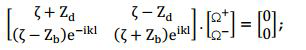
Applications Claiming Priority (1)
| Application Number | Priority Date | Filing Date | Title |
|---|---|---|---|
| PCT/GB2008/051144 WO2010063982A1 (en) | 2008-12-02 | 2008-12-02 | Method and apparatus for reducing stick-slip |
Publications (2)
| Publication Number | Publication Date |
|---|---|
| BRPI0822972A2 BRPI0822972A2 (en) | 2015-06-23 |
| BRPI0822972B1 true BRPI0822972B1 (en) | 2023-01-17 |
Family
ID=40852329
Family Applications (1)
| Application Number | Title | Priority Date | Filing Date |
|---|---|---|---|
| BRPI0822972-4A BRPI0822972B1 (en) | 2008-12-02 | 2008-12-02 | METHOD FOR REDUCING GRIP AND RELEASE TORSIONAL VIBRATION OSCILLATION, METHOD FOR DRILLING A WELL, METHOD FOR UPGRADING A DRILLING MECHANISM ON A DRILLING PLATFORM AND APPARATUS |
Country Status (8)
| Country | Link |
|---|---|
| US (2) | US9581008B2 (en) |
| EP (1) | EP2364397B1 (en) |
| BR (1) | BRPI0822972B1 (en) |
| CA (1) | CA2745198C (en) |
| MX (1) | MX2011005523A (en) |
| PL (1) | PL2364397T3 (en) |
| RU (1) | RU2478781C2 (en) |
| WO (1) | WO2010063982A1 (en) |
Families Citing this family (55)
| Publication number | Priority date | Publication date | Assignee | Title |
|---|---|---|---|---|
| EP2364397B1 (en) | 2008-12-02 | 2013-01-02 | National Oilwell Varco, L.P. | Method and apparatus for reducing stick-slip |
| MX2011005529A (en) * | 2008-12-02 | 2011-06-16 | Nat Oilwell Varco Lp | Method and apparatus for estimating the instantaneous rotational speed of a bottom hole assembly. |
| CA2774551C (en) | 2009-09-21 | 2015-11-17 | National Oilwell Varco, L.P. | Systems and methods for improving drilling efficiency |
| CN103270243B (en) * | 2010-12-22 | 2016-07-06 | 国际壳牌研究有限公司 | Control the vibration in well system |
| US9436173B2 (en) | 2011-09-07 | 2016-09-06 | Exxonmobil Upstream Research Company | Drilling advisory systems and methods with combined global search and local search methods |
| EP2570589A1 (en) * | 2011-09-16 | 2013-03-20 | Vetco Gray Controls Limited | Setting the value of an operational parameter of a well |
| NL2007656C2 (en) * | 2011-10-25 | 2013-05-01 | Cofely Experts B V | A method of and a device and an electronic controller for mitigating stick-slip oscillations in borehole equipment. |
| CA2856004A1 (en) | 2011-11-25 | 2013-05-30 | Shell Internationale Research Maatschappij B.V. | Method and system for controlling vibrations in a drilling system |
| US9297743B2 (en) | 2011-12-28 | 2016-03-29 | Schlumberger Technology Corporation | Determination of stick slip conditions |
| NO333959B1 (en) | 2012-01-24 | 2013-10-28 | Nat Oilwell Varco Norway As | Method and system for reducing drill string oscillation |
| US9482084B2 (en) | 2012-09-06 | 2016-11-01 | Exxonmobil Upstream Research Company | Drilling advisory systems and methods to filter data |
| RU2508447C1 (en) * | 2013-02-12 | 2014-02-27 | Общество С Ограниченной Ответственностью "Вниибт-Буровой Инструмент" | Method of control over hydraulic face motor under face conditions |
| CN105143599B (en) | 2013-03-20 | 2018-05-01 | 普拉德研究及开发股份有限公司 | Well system controls |
| US9920612B2 (en) | 2013-03-21 | 2018-03-20 | Shell Oil Company | Method and system for damping vibrations in a tool string system |
| US9657523B2 (en) * | 2013-05-17 | 2017-05-23 | Baker Hughes Incorporated | Bottomhole assembly design method to reduce rotational loads |
| EA038672B1 (en) * | 2013-06-27 | 2021-10-01 | Шлюмбергер Текнолоджи Бв | Method for changing set points in a resonant system |
| US9695956B2 (en) | 2013-07-29 | 2017-07-04 | Dresser, Inc. | Spectral analysis based detector for a control valve |
| GB2532360B (en) * | 2013-08-17 | 2020-02-26 | Halliburton Energy Services Inc | Methods and systems to optimize drilling efficiency while reducing stick slip |
| MX2016002003A (en) * | 2013-09-17 | 2016-05-18 | Halliburton Energy Services Inc | Removal of stick-slip vibrations in a drilling assembly. |
| CN105793513B (en) * | 2013-12-23 | 2018-06-22 | 哈里伯顿能源服务公司 | The independent modification of drill string sections rotary speed |
| EP3152393B1 (en) * | 2014-06-05 | 2019-07-24 | National Oilwell Varco Norway AS | Method and device for estimating downhole string variables |
| CN106133268B (en) * | 2014-06-27 | 2019-03-15 | 哈利伯顿能源服务公司 | Use the micro- stall and stick slip in fiber sensor measuring mud motor |
| US9689250B2 (en) | 2014-11-17 | 2017-06-27 | Tesco Corporation | System and method for mitigating stick-slip |
| CN107075911B (en) * | 2014-12-29 | 2019-11-08 | 哈里伯顿能源服务公司 | Mitigate the stick-slip effect in rotary steering tool |
| GB2550849B (en) * | 2016-05-23 | 2020-06-17 | Equinor Energy As | Interface and integration method for external control of the drilling control system |
| NL2016859B1 (en) * | 2016-05-30 | 2017-12-11 | Engie Electroproject B V | A method of and a device for estimating down hole speed and down hole torque of borehole drilling equipment while drilling, borehole equipment and a computer program product. |
| EP3258056B1 (en) * | 2016-06-13 | 2019-07-24 | VAREL EUROPE (Société par Actions Simplifiée) | Passively induced forced vibration rock drilling system |
| US11015425B2 (en) | 2016-07-29 | 2021-05-25 | Halliburton Energy Services, Inc. | Mitigating vibrations in a drilling system |
| EP3551847B1 (en) * | 2016-12-09 | 2023-03-15 | Halliburton Energy Services, Inc. | Downhole drilling methods and systems with top drive motor torque commands based on a dynamics model |
| US10539000B2 (en) * | 2016-12-30 | 2020-01-21 | Nabors Drilling Technologies Usa, Inc. | Instrumented saver sub for stick-slip vibration mitigation |
| US10590709B2 (en) | 2017-07-18 | 2020-03-17 | Reme Technologies Llc | Downhole oscillation apparatus |
| WO2019050824A1 (en) * | 2017-09-05 | 2019-03-14 | Schlumberger Technology Corporation | Controlling drill string rotation |
| US10907463B2 (en) | 2017-09-12 | 2021-02-02 | Schlumberger Technology Corporation | Well construction control system |
| US10782197B2 (en) | 2017-12-19 | 2020-09-22 | Schlumberger Technology Corporation | Method for measuring surface torque oscillation performance index |
| AR114505A1 (en) | 2018-01-05 | 2020-09-16 | Conocophillips Co | SYSTEM AND METHOD FOR ATTENUATING VIBRATION DUE TO BLOCKING AND SLIPPING |
| US10760417B2 (en) | 2018-01-30 | 2020-09-01 | Schlumberger Technology Corporation | System and method for surface management of drill-string rotation for whirl reduction |
| US11208853B2 (en) | 2018-03-15 | 2021-12-28 | Baker Hughes, A Ge Company, Llc | Dampers for mitigation of downhole tool vibrations and vibration isolation device for downhole bottom hole assembly |
| AR123395A1 (en) | 2018-03-15 | 2022-11-30 | Baker Hughes A Ge Co Llc | DAMPERS TO MITIGATE VIBRATIONS OF DOWNHOLE TOOLS AND VIBRATION ISOLATION DEVICE FOR DOWNHOLE ARRANGEMENTS |
| US11448015B2 (en) | 2018-03-15 | 2022-09-20 | Baker Hughes, A Ge Company, Llc | Dampers for mitigation of downhole tool vibrations |
| US11199242B2 (en) | 2018-03-15 | 2021-12-14 | Baker Hughes, A Ge Company, Llc | Bit support assembly incorporating damper for high frequency torsional oscillation |
| CA3094358C (en) | 2018-05-31 | 2023-01-17 | Halliburton Energy Services, Inc. | Method and system for stick-slip mitigation |
| GB2588024B (en) | 2018-06-01 | 2022-12-07 | Schlumberger Technology Bv | Estimating downhole RPM oscillations |
| WO2020101812A1 (en) * | 2018-11-16 | 2020-05-22 | Halliburton Energy Services, Inc. | Advisory system for stick-slip mitigation in drilling systems |
| US11704453B2 (en) * | 2019-06-06 | 2023-07-18 | Halliburton Energy Services, Inc. | Drill bit design selection and use |
| US11187714B2 (en) | 2019-07-09 | 2021-11-30 | Schlumberger Technology Corporation | Processing downhole rotational data |
| GB2603674B (en) | 2019-09-12 | 2023-06-28 | Baker Hughes Oilfield Operations Llc | Vibration isolating coupler for reducing vibrations in a drill string |
| US11519227B2 (en) | 2019-09-12 | 2022-12-06 | Baker Hughes Oilfield Operations Llc | Vibration isolating coupler for reducing high frequency torsional vibrations in a drill string |
| US11952883B2 (en) | 2019-09-18 | 2024-04-09 | Halliburton Energy Services, Inc. | System and method for mitigating stick-slip |
| US11391142B2 (en) | 2019-10-11 | 2022-07-19 | Schlumberger Technology Corporation | Supervisory control system for a well construction rig |
| US11814942B2 (en) * | 2019-11-04 | 2023-11-14 | Schlumberger Technology Corporation | Optimizing algorithm for controlling drill string driver |
| US11916507B2 (en) | 2020-03-03 | 2024-02-27 | Schlumberger Technology Corporation | Motor angular position control |
| US11933156B2 (en) | 2020-04-28 | 2024-03-19 | Schlumberger Technology Corporation | Controller augmenting existing control system |
| US11748531B2 (en) | 2020-10-19 | 2023-09-05 | Halliburton Energy Services, Inc. | Mitigation of high frequency coupled vibrations in PDC bits using in-cone depth of cut controllers |
| CN112360426A (en) * | 2020-11-13 | 2021-02-12 | 黑龙江景宏石油设备制造有限公司 | Drilling top drive control system and method |
| CN116022871B (en) * | 2023-02-21 | 2024-04-12 | 昆明理工大学 | Water purification treatment cascade feedback PLC automatic control system and control method thereof |
Family Cites Families (27)
| Publication number | Priority date | Publication date | Assignee | Title |
|---|---|---|---|---|
| US4535972A (en) * | 1983-11-09 | 1985-08-20 | Standard Oil Co. (Indiana) | System to control the vertical movement of a drillstring |
| GB9003759D0 (en) | 1990-02-20 | 1990-04-18 | Shell Int Research | Method and system for controlling vibrations in borehole equipment |
| FR2713700B1 (en) | 1993-12-08 | 1996-03-15 | Inst Francais Du Petrole | Method and system for controlling the stability of the rotation speed of a drilling tool. |
| US5559415A (en) * | 1994-06-30 | 1996-09-24 | Honeywell Inc. | Integrator management for redundant active hand controllers |
| US6206108B1 (en) | 1995-01-12 | 2001-03-27 | Baker Hughes Incorporated | Drilling system with integrated bottom hole assembly |
| RU2108456C1 (en) | 1996-04-29 | 1998-04-10 | Вячеслав Георгиевич Алферов | Method for adjusting electric drive of bit feed regulator |
| FR2750160B1 (en) * | 1996-06-24 | 1998-08-07 | Inst Francais Du Petrole | METHOD AND SYSTEM FOR REAL-TIME ESTIMATION OF AT LEAST ONE PARAMETER RELATED TO THE MOVEMENT OF A DRILLING TOOL |
| AUPO241996A0 (en) * | 1996-09-19 | 1996-10-10 | University Of Newcastle Research Associates Limited, The | Method & apparatus for automated tuning of pid-controllers |
| GB9620679D0 (en) * | 1996-10-04 | 1996-11-20 | Halliburton Co | Method and apparatus for sensing and displaying torsional vibration |
| EP0870899A1 (en) | 1997-04-11 | 1998-10-14 | Shell Internationale Researchmaatschappij B.V. | Drilling assembly with reduced stick-slip tendency |
| JPH11332272A (en) | 1998-05-15 | 1999-11-30 | Toyo Electric Mfg Co Ltd | Dual inertia resonance system torque control method |
| US6327539B1 (en) * | 1998-09-09 | 2001-12-04 | Shell Oil Company | Method of determining drill string stiffness |
| US6948572B2 (en) | 1999-07-12 | 2005-09-27 | Halliburton Energy Services, Inc. | Command method for a steerable rotary drilling device |
| US6993456B2 (en) * | 1999-09-30 | 2006-01-31 | Rockwell Automation Technologies, Inc. | Mechanical-electrical template based method and apparatus |
| US6541950B2 (en) * | 2000-01-26 | 2003-04-01 | Novatel, Inc. | Multipath meter |
| RU2234116C1 (en) | 2002-12-24 | 2004-08-10 | Северо-Кавказский государственный технический университет | Device for pid-regulation |
| US7518950B2 (en) | 2005-03-29 | 2009-04-14 | Baker Hughes Incorporated | Method and apparatus for downlink communication |
| US7983113B2 (en) | 2005-03-29 | 2011-07-19 | Baker Hughes Incorporated | Method and apparatus for downlink communication using dynamic threshold values for detecting transmitted signals |
| US7173399B2 (en) * | 2005-04-19 | 2007-02-06 | General Electric Company | Integrated torsional mode damping system and method |
| WO2009012591A1 (en) * | 2007-07-23 | 2009-01-29 | Athena Industrial Technologies Inc. | Drill bit tracking apparatus and method |
| US20090120689A1 (en) | 2007-11-12 | 2009-05-14 | Baker Hughes Incorporated | Apparatus and method for communicating information between a wellbore and surface |
| CA2642713C (en) | 2008-11-03 | 2012-08-07 | Halliburton Energy Services, Inc. | Drilling apparatus and method |
| EP2364397B1 (en) | 2008-12-02 | 2013-01-02 | National Oilwell Varco, L.P. | Method and apparatus for reducing stick-slip |
| MX2011005529A (en) | 2008-12-02 | 2011-06-16 | Nat Oilwell Varco Lp | Method and apparatus for estimating the instantaneous rotational speed of a bottom hole assembly. |
| EP2462315B1 (en) | 2009-08-07 | 2018-11-14 | Exxonmobil Upstream Research Company | Methods to estimate downhole drilling vibration amplitude from surface measurement |
| BR112012012388B1 (en) | 2009-11-24 | 2019-09-24 | Baker Hughes Incorporated | POWDER HOUSE APPLIANCE |
| US8453764B2 (en) | 2010-02-01 | 2013-06-04 | Aps Technology, Inc. | System and method for monitoring and controlling underground drilling |
-
2008
- 2008-12-02 EP EP08875686A patent/EP2364397B1/en active Active
- 2008-12-02 CA CA2745198A patent/CA2745198C/en active Active
- 2008-12-02 RU RU2011127193/03A patent/RU2478781C2/en active
- 2008-12-02 US US13/132,421 patent/US9581008B2/en active Active
- 2008-12-02 WO PCT/GB2008/051144 patent/WO2010063982A1/en active Application Filing
- 2008-12-02 BR BRPI0822972-4A patent/BRPI0822972B1/en not_active IP Right Cessation
- 2008-12-02 PL PL08875686T patent/PL2364397T3/en unknown
- 2008-12-02 MX MX2011005523A patent/MX2011005523A/en active IP Right Grant
-
2016
- 2016-12-22 US US15/388,555 patent/US10415364B2/en active Active
Also Published As
| Publication number | Publication date |
|---|---|
| RU2011127193A (en) | 2013-01-10 |
| RU2478781C2 (en) | 2013-04-10 |
| CA2745198C (en) | 2014-10-14 |
| EP2364397B1 (en) | 2013-01-02 |
| PL2364397T3 (en) | 2013-06-28 |
| US20110232966A1 (en) | 2011-09-29 |
| WO2010063982A1 (en) | 2010-06-10 |
| MX2011005523A (en) | 2011-06-16 |
| US9581008B2 (en) | 2017-02-28 |
| BRPI0822972A2 (en) | 2015-06-23 |
| US10415364B2 (en) | 2019-09-17 |
| EP2364397A1 (en) | 2011-09-14 |
| CA2745198A1 (en) | 2010-06-10 |
| US20170101861A1 (en) | 2017-04-13 |
Similar Documents
| Publication | Publication Date | Title |
|---|---|---|
| BRPI0822972B1 (en) | METHOD FOR REDUCING GRIP AND RELEASE TORSIONAL VIBRATION OSCILLATION, METHOD FOR DRILLING A WELL, METHOD FOR UPGRADING A DRILLING MECHANISM ON A DRILLING PLATFORM AND APPARATUS | |
| US10533407B2 (en) | Methods and apparatus for reducing stick-slip | |
| EP2807332B1 (en) | Method for reducing drillstring oscillations | |
| Kyllingstad et al. | A new stick-slip prevention system | |
| EP3152393B1 (en) | Method and device for estimating downhole string variables | |
| US20150322766A1 (en) | A method of and a device for determining operational parameters of a computational model of borehole equipment, an electronic controller and borehole equipment |
Legal Events
| Date | Code | Title | Description |
|---|---|---|---|
| B06F | Objections, documents and/or translations needed after an examination request according [chapter 6.6 patent gazette] | ||
| B07A | Application suspended after technical examination (opinion) [chapter 7.1 patent gazette] | ||
| B09B | Patent application refused [chapter 9.2 patent gazette] | ||
| B12B | Appeal against refusal [chapter 12.2 patent gazette] | ||
| B16A | Patent or certificate of addition of invention granted [chapter 16.1 patent gazette] |
Free format text: PRAZO DE VALIDADE: 20 (VINTE) ANOS CONTADOS A PARTIR DE 02/12/2008, OBSERVADAS AS CONDICOES LEGAIS. PATENTE CONCEDIDA CONFORME ADI 5.529/DF, QUE DETERMINA A ALTERACAO DO PRAZO DE CONCESSAO. |
|
| B21F | Lapse acc. art. 78, item iv - on non-payment of the annual fees in time |
Free format text: REFERENTE A 14A ANUIDADE. |
|
| B24J | Lapse because of non-payment of annual fees (definitively: art 78 iv lpi, resolution 113/2013 art. 12) |
Free format text: EM VIRTUDE DA EXTINCAO PUBLICADA NA RPI 2716 DE 24-01-2023 E CONSIDERANDO AUSENCIA DE MANIFESTACAO DENTRO DOS PRAZOS LEGAIS, INFORMO QUE CABE SER MANTIDA A EXTINCAO DA PATENTE E SEUS CERTIFICADOS, CONFORME O DISPOSTO NO ARTIGO 12, DA RESOLUCAO 113/2013. |