EP2181238B1 - Outils de forage ayant des poches pour recevoir des elements de coupe et procedes pour former des outils de forage comprenant de telles poches - Google Patents
Outils de forage ayant des poches pour recevoir des elements de coupe et procedes pour former des outils de forage comprenant de telles poches Download PDFInfo
- Publication number
- EP2181238B1 EP2181238B1 EP08797782A EP08797782A EP2181238B1 EP 2181238 B1 EP2181238 B1 EP 2181238B1 EP 08797782 A EP08797782 A EP 08797782A EP 08797782 A EP08797782 A EP 08797782A EP 2181238 B1 EP2181238 B1 EP 2181238B1
- Authority
- EP
- European Patent Office
- Prior art keywords
- recess
- cutting element
- earth
- forming
- blade
- Prior art date
- Legal status (The legal status is an assumption and is not a legal conclusion. Google has not performed a legal analysis and makes no representation as to the accuracy of the status listed.)
- Active
Links
- 238000005520 cutting process Methods 0.000 title claims abstract description 180
- 238000000034 method Methods 0.000 title claims abstract description 57
- 239000000463 material Substances 0.000 claims abstract description 69
- 239000000945 filler Substances 0.000 claims abstract description 55
- 238000003754 machining Methods 0.000 claims abstract description 29
- 239000007787 solid Substances 0.000 claims description 24
- 229910045601 alloy Inorganic materials 0.000 claims description 15
- 239000000956 alloy Substances 0.000 claims description 15
- 239000000843 powder Substances 0.000 claims description 11
- 238000005245 sintering Methods 0.000 claims description 9
- 238000003466 welding Methods 0.000 claims description 9
- 239000002131 composite material Substances 0.000 claims description 8
- 239000011159 matrix material Substances 0.000 claims description 8
- 238000005219 brazing Methods 0.000 claims description 7
- 238000005552 hardfacing Methods 0.000 claims description 6
- 239000000203 mixture Substances 0.000 claims description 4
- 229910000679 solder Inorganic materials 0.000 claims description 3
- 238000003825 pressing Methods 0.000 claims description 2
- 238000005553 drilling Methods 0.000 description 23
- 230000015572 biosynthetic process Effects 0.000 description 17
- 238000005755 formation reaction Methods 0.000 description 17
- 239000011800 void material Substances 0.000 description 11
- 229910000831 Steel Inorganic materials 0.000 description 10
- 239000010959 steel Substances 0.000 description 10
- 238000003801 milling Methods 0.000 description 4
- 239000000853 adhesive Substances 0.000 description 3
- 230000001070 adhesive effect Effects 0.000 description 3
- 230000000295 complement effect Effects 0.000 description 3
- 229910003460 diamond Inorganic materials 0.000 description 3
- 239000010432 diamond Substances 0.000 description 3
- 238000004519 manufacturing process Methods 0.000 description 3
- 229910052751 metal Inorganic materials 0.000 description 3
- 239000002184 metal Substances 0.000 description 3
- 239000002245 particle Substances 0.000 description 3
- 230000035515 penetration Effects 0.000 description 3
- 230000007704 transition Effects 0.000 description 3
- UONOETXJSWQNOL-UHFFFAOYSA-N tungsten carbide Chemical compound [W+]#[C-] UONOETXJSWQNOL-UHFFFAOYSA-N 0.000 description 3
- IJGRMHOSHXDMSA-UHFFFAOYSA-N Atomic nitrogen Chemical compound N#N IJGRMHOSHXDMSA-UHFFFAOYSA-N 0.000 description 2
- PXHVJJICTQNCMI-UHFFFAOYSA-N Nickel Chemical compound [Ni] PXHVJJICTQNCMI-UHFFFAOYSA-N 0.000 description 2
- 230000008901 benefit Effects 0.000 description 2
- 230000003628 erosive effect Effects 0.000 description 2
- 239000012530 fluid Substances 0.000 description 2
- 230000008595 infiltration Effects 0.000 description 2
- 238000001764 infiltration Methods 0.000 description 2
- 229910001092 metal group alloy Inorganic materials 0.000 description 2
- 238000005476 soldering Methods 0.000 description 2
- RYGMFSIKBFXOCR-UHFFFAOYSA-N Copper Chemical compound [Cu] RYGMFSIKBFXOCR-UHFFFAOYSA-N 0.000 description 1
- 229910000760 Hardened steel Inorganic materials 0.000 description 1
- 238000005299 abrasion Methods 0.000 description 1
- 239000003082 abrasive agent Substances 0.000 description 1
- 230000001154 acute effect Effects 0.000 description 1
- 238000007792 addition Methods 0.000 description 1
- 238000005266 casting Methods 0.000 description 1
- 229910017052 cobalt Inorganic materials 0.000 description 1
- 239000010941 cobalt Substances 0.000 description 1
- GUTLYIVDDKVIGB-UHFFFAOYSA-N cobalt atom Chemical compound [Co] GUTLYIVDDKVIGB-UHFFFAOYSA-N 0.000 description 1
- 229910052802 copper Inorganic materials 0.000 description 1
- 239000010949 copper Substances 0.000 description 1
- 238000012217 deletion Methods 0.000 description 1
- 230000037430 deletion Effects 0.000 description 1
- 238000013461 design Methods 0.000 description 1
- 230000001747 exhibiting effect Effects 0.000 description 1
- 239000007789 gas Substances 0.000 description 1
- 238000003780 insertion Methods 0.000 description 1
- 230000037431 insertion Effects 0.000 description 1
- 239000007788 liquid Substances 0.000 description 1
- 229910001338 liquidmetal Inorganic materials 0.000 description 1
- 238000012986 modification Methods 0.000 description 1
- 230000004048 modification Effects 0.000 description 1
- 229910052759 nickel Inorganic materials 0.000 description 1
- 229910052757 nitrogen Inorganic materials 0.000 description 1
- 239000003208 petroleum Substances 0.000 description 1
- 239000000758 substrate Substances 0.000 description 1
- 238000007514 turning Methods 0.000 description 1
- 238000010792 warming Methods 0.000 description 1
Images


Classifications
-
- E—FIXED CONSTRUCTIONS
- E21—EARTH OR ROCK DRILLING; MINING
- E21B—EARTH OR ROCK DRILLING; OBTAINING OIL, GAS, WATER, SOLUBLE OR MELTABLE MATERIALS OR A SLURRY OF MINERALS FROM WELLS
- E21B10/00—Drill bits
- E21B10/62—Drill bits characterised by parts, e.g. cutting elements, which are detachable or adjustable
- E21B10/627—Drill bits characterised by parts, e.g. cutting elements, which are detachable or adjustable with plural detachable cutting elements
- E21B10/633—Drill bits characterised by parts, e.g. cutting elements, which are detachable or adjustable with plural detachable cutting elements independently detachable
-
- Y—GENERAL TAGGING OF NEW TECHNOLOGICAL DEVELOPMENTS; GENERAL TAGGING OF CROSS-SECTIONAL TECHNOLOGIES SPANNING OVER SEVERAL SECTIONS OF THE IPC; TECHNICAL SUBJECTS COVERED BY FORMER USPC CROSS-REFERENCE ART COLLECTIONS [XRACs] AND DIGESTS
- Y10—TECHNICAL SUBJECTS COVERED BY FORMER USPC
- Y10T—TECHNICAL SUBJECTS COVERED BY FORMER US CLASSIFICATION
- Y10T29/00—Metal working
- Y10T29/49—Method of mechanical manufacture
- Y10T29/4998—Combined manufacture including applying or shaping of fluent material
- Y10T29/49993—Filling of opening
Definitions
- the present invention relates generally to earth-boring tools and methods of forming earth-boring tools. More particularly, embodiments of the present invention relate to methods of securing cutting elements to earth-boring tools and to tools formed using such methods.
- Rotary drill bits are commonly used for drilling bore holes or wells in earth formations.
- One type of rotary drill bit is the fixed-cutter bit (often referred to as a "drag" bit), which typically includes a plurality of cutting elements secured to a face region of a bit body.
- a conventional fixed-cutter earth-boring rotary drill bit 100 includes a bit body 102 that has generally radially-projecting and longitudinally-extending wings or blades 104, which are separated by junk slots 106.
- a plurality of cutting elements 108 is positioned on each of the blades 104.
- the cutting elements 108 have either a disk shape or, in some instances, a more elongated, substantially cylindrical shape.
- the cutting elements 108 commonly comprise a "table" of super-abrasive material, such as mutually bound particles of polycrystalline diamond, formed on a supporting substrate of a hard material, conventionally cemented tungsten carbide. Such cutting elements are often referred to as "polycrystalline diamond compact” (PDC) cutting elements or cutters.
- PDC polycrystalline diamond compact
- the plurality of PDC cutting elements 108 may be provided within cutting element pockets 110 formed in rotationally leading surfaces of each of the blades 104.
- the PDC cutting elements 108 may be supported from behind (taken in the direction of bit rotation) by buttresses 112, which may be integrally formed with the bit body 102.
- a bonding material such as an adhesive or, more typically, a braze alloy may be used to secure the cutting elements 108 to the bit body 102.
- the bit body 102 of a rotary drill bit 100 typically is secured to a hardened steel shank having an American Petroleum Institute (API) thread connection 114 for attaching the drill bit 100 to a drill string (not shown).
- the drill string includes tubular pipe and component segments coupled end to end between the drill bit and other drilling equipment at the surface.
- Equipment such as a rotary table or top drive may be used for rotating the drill string and the drill bit within the bore hole.
- the shank of the drill bit may be coupled to the drive shaft of a down-hole motor, which then may be used to rotate the drill bit, alone or in combination with rotation of the drill string from the surface.
- the drill bit 100 is positioned at the bottom of a well bore hole and rotated. Drilling fluid is pumped through the inside of the bit body 102, and out through the nozzles 116. As the drill bit 100 is rotated, the PDC cutting elements 108 scrape across and shear away the underlying earth formation material. The formation cuttings mix with the drilling fluid and pass through the junk slots 106, up through an annular space between the wall of the bore hole and the outer surface of the drill string to the surface of the earth formation.
- the bit body 102 of a fixed-cutter rotary drill bit 100 may be formed from steel.
- Such steel bit bodies are typically fabricated by machining a steel blank (using conventional machining processes including, for example, turning, milling, and drilling) to form the blades 104, junk slots 106, pockets 110, buttresses 112, and other features of the drill bit 100.
- the cutting elements 108 of an earth-boring rotary drill bit often have a generally cylindrical shape. Therefore, to form a pocket 110 for receiving such a cutting element 108 therein, it may be necessary or desirable to form a recess into the body of a drill bit that has the shape of a flat-ended, right cylinder.
- a recess may be machined into the body of a drill bit by, for example, using a drilling or milling machine to plunge a rotating flat-bottomed end mill cutter into the body of a drill bit along the axis of rotation of the cutter.
- Such a machining operation may yield a cutting element pocket 110 having a substantially cylindrical surface and a substantially planar inner end surface for disposing and brazing a generally cylindrical cutting element 108 therein.
- the interference caused by blade 206 may inhibit the use of a desired machining path for a machining tool that is aligned generally along the axis of rotation thereof because at least one of the machining tool and the collet or chuck that retains the machining tool may contact adjacent blade 206.
- the machining tool may be required to remove a portion of adjacent blade 206.
- United States Patent No. 7,070,011 to Sherwood, Jr., et al. discloses steel body rotary drill bits having primary cutting elements that are disposed in cutter pocket recesses that are partially defined by cutter support elements.
- the support elements are affixed to the steel body during fabrication of the drill bits.
- At least a portion of the body of each cutting element is secured to a surface of the steel bit body, and at least another portion of the body of each cutting element matingly engages a surface of one of the support elements.
- US 2006/0278441 A1 which is considered the closest prior art, discloses a cutting element assembly positioned in a bit blade.
- a cutting element is positioned generally within a cutting pocket portion and a base member of the cutting element assembly is positioned generally within a recess formed within a support portion.
- a structural element extends through a hole in the bit blade and is attached to the base member to affix the cutting element to the bit blade.
- US-A- 4 782 903 discloses threaded insert studs for insertion into a drilling bit body.
- the threaded insert stud is secured in a hole in the drilling bit by a lock nut that is disposed in a portion of the hole having a relatively larger diameter.
- US 5558170 A teaches a bullet-shaped cutter having a semicircular receptacle that is configured to receive a portion of pin.
- a pocket of a drill bit also includes a semicircular receptacle formed in the spherical end of the pocket to receive the other portion of the pin when the cutter is placed in the pocket.
- the pin only forms a relatively small portion of a back surface of the cutting element pocket.
- the object of the invention is to provide a method for forming cutting element pockets on earth boring rotary drill bits that avoid tool path interference problems and that do not require use of additional support elements.
- the present invention includes methods of forming one or more cutting element pockets in a surface of an earth-boring tool such as, for example, a fixed cutter rotary drill bit, a roller cone rotary drill bit, a core bit, an eccentric bit, a bicenter bit, a reamer, or a mill.
- the methods include using a rotating cutter to machine a cutting element pocket in such a way as to avoid mechanical tool interference problems and forming the pocket so as to sufficiently support a cutting element therein.
- methods of the present invention may include machining a first recess in a bit body of an earth-boring tool to define a lateral sidewall surface of a cutting element pocket.
- a second recess may be machined in the bit body to define at least a portion of a shoulder at an intersection with the first recess. Additionally, a filler material may be disposed within the second recess to define at least a portion of an end surface of the cutting element pocket.
- the present invention includes methods of forming an earth-boring tool such as, for example, any of those mentioned above.
- the methods include forming a bit body and using a rotating cutter to machine at least a portion of a cutting element pocket in the bit body in a manner that avoids mechanical tool interference problems and allows the pocket to be formed so as to sufficiently support a cutting element therein.
- the present invention includes earth-boring tools having a bit body comprising a first recess defining a lateral sidewall surface of a cutting element pocket, a second recess located rotationally behind the first recess along a longitudinal axis of the cutting element pocket, and a shoulder region at an intersection between the first and second recesses providing a position for an inner end surface of the cutting element pocket.
- a filler material may be disposed within the second recess and abutting the shoulder region, the filler material defining at least a portion of an inner end surface of the cutting element pocket.
- the present invention includes methods of forming cutting element pockets that avoid or overcome at least some of the interference problems associated with previously known methods of forming such pockets, as well as drilling tools including the resulting cutting element pockets that are formed using such methods.
- cutting diameter means the largest diameter of a machine tool cutter, such as a drill bit, a router, or a mill, taken perpendicular to a longitudinal axis of the cutter about which the cutter is rotated while the cutter is used to cut a workpiece.
- rotationally leading surface when used with respect to a blade of an earth-boring tool, means a surface on a blade that leads the blade through rotation in a cutting direction of a body of a bit or other subterranean drilling tool about an axis.
- rotationally trailing surface when used with respect to a blade of an earth-boring tool, means a surface on a blade that trails the blade through rotation as the blade rotates about the bit or other tool body axis in a cutting direction.
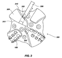
- FIG. 3 is a plan view of the face of an earth-boring rotary drill bit 300 illustrating a recess 302 being formed in a bit body 304 according to one embodiment.
- the recess 302 may be formed in a blade 306 on bit body 304 using a machining process.
- recess 302 may be formed using a rotating cutter 308 of a multi-axis milling or drilling machine (not shown).
- recess 302 may be formed by plunging rotating cutter 308 into bit body 304 from an entry point at or near the rotationally trailing surface 310 of blade 306.
- rotating cutter 308 may continue through blade 306 until it exits at or near the rotationally leading surface 312 of blade 306.
- rotating cutter 308 may enter the bit body 304 at the rotationally trailing surface 310 of blade 306, the previously described mechanical interference problems associated with machining a recess 302 in a bit body 304 may be reduced or eliminated and a cutting element pocket may be created that enables the positioning of cutting elements with a low back rake angle.
- the recess 302 may have a shape that is complementary to, or that corresponds with, an exterior shape of a cutting element to be secured at least partially within the recess 302, as described in further detail below.
- the cutting element to be secured in a cutting element pocket may have a generally cylindrical body comprising a generally cylindrical lateral sidewall surface extending between two substantially planar end surfaces. Such configurations are commonly used for polycrystalline diamond compact (PDC) cutters.
- the recess 302 may have a generally cylindrical shape that is complementary to that of the cutting element to be secured therein.
- the rotating cutter 308 may have a cutting diameter that is substantially the same as the diameter of the desired recess 302. In other embodiments, the cutting diameter of rotating cutter 308 may have a cutting diameter substantially smaller than the desired diameter of recess 302 as will be discussed in more detail below.
- FIG. 4 is a partial cross-sectional view of a bit body 404 and illustrates the formation of a cutting element pocket 414 by forming first recess 402 that extends through the blade 406 from a location on or near a rotationally trailing surface 410 of the blade 406 to portions of one or both of the rotationally leading surface 407 and the outer surface 409 of blade 406.
- Rotating cutter 408 may enter blade 406 from the location at or near the rotationally trailing surface 410.
- the rotating cutter 408 may be oriented along a longitudinal axis 411 of cutting element pocket 414 as the first recess 402 is formed in blade 406.
- Rotating cutter 408 may form first recess 402 by machining in the directions of the arrows as rotating cutter 408 is rotated.
- First recess 402 may define at least a portion of a lateral sidewall surface 413 of cutting element pocket 414.
- first recess 402 is substantially the same diameter throughout and, thus, there may be no definition as to where a cutting element pocket may end.
- Such a back surface of the cutting element pocket 414 may be formed as described in further detail below.
- FIG. 5 illustrates a second recess 416 being formed in the blade 406 using a rotating cutter 418.
- the second recess 416 may extend partially through the blade 406 toward the rotationally leading surface 407 thereof from a location on or near the rotationally trailing surface 410 of the blade 406. At least a portion of the second recess 416 may be positioned below and be at least partially covered by the outer surface 409 of blade 406.
- Rotating cutter 418 may enter blade 406 from the location at or near the rotationally trailing surface 410, and also may be oriented along, and concentric with, the longitudinal axis 411 of cutting element pocket 414 in the manner previously described with respect to formation of the first recess 402.
- the second recess 416 may have a shape (e.g., round) generally similar to that of the first recess.
- the second recess 416 may be larger than the first recess 402 in at least one cross-sectional dimension such that a shoulder 412 is formed at the transition or intersection between the first recess 402 and the second recess 416.
- the shoulder 412 may define, or may be used to define, a location of a back surface of the cutting element pocket 414 being formed, as described in further detail below. As illustrated in FIG. 5 , shoulder 412 comprises a substantially annular shoulder.
- second recess 416 may be formed by machining a counterbore using a rotating cutter 418 having a cutting diameter larger than the cutting diameter of rotating cutter 408 ( FIG. 4 ), as shown in FIG. 5 .
- Rotating cutter 418 may be oriented along the longitudinal axis 411 of cutting element pocket 414 and plunged into the blade 406 to a desired depth from the rotationally trailing surface 410.
- the depth of second recess 416 may be determined by designers according to the specific needs of the earth-boring drill bit and the specific length of the cutting elements to be disposed in cutting element pocket 414.
- the rotating cutter used to create the first and/or second recess 402, 416 may be substantially smaller than the recess to be formed.
- FIG. 6 illustrates a partial cross-sectional view of a bit body 404 having a first recess 402 formed in blade 406 with a rotating cutter 608.
- Rotating cutter 608 may have a cutting diameter that is substantially smaller than the desired diameter of first recess 402 formed in blade 406.
- rotating cutter 608 may be moved in the directions of the arrows shown in FIGS. 6 and 7B to form first recess 402 oriented along longitudinal axis 411 of cutting element pocket 414.
- FIG. 6 illustrates a partial cross-sectional view of a bit body 404 having a first recess 402 formed in blade 406 with a rotating cutter 608.
- Rotating cutter 608 may have a cutting diameter that is substantially smaller than the desired diameter of first recess 402 formed in blade 406.
- rotating cutter 608 may be moved in the directions of the arrows shown in FIG
- FIG. 7A illustrates another rotating cutter 608' of relatively small diameter and having a flat, distal end face being used to enlarge first recess 402 to form second recess 416 and shoulder 412 by machining the blade 406 generally parallel to, but laterally offset from, longitudinal axis 411 of cutting element pocket 414.
- FIG. 7B is a cross-sectional view of the bit body 404 shown in FIG. 7A taken along section line 7B-7B shown therein.
- FIG. 7B illustrates a rotating cutter 608 inside second recess 416.
- first and second recesses 402, 416 are shown as having a circular cross-section, it will be appreciated by one of ordinary skill that first and second recesses 402, 416 may be formed with any cross-section suitable for different shapes and configurations of cutting elements.
- first recess 402 and/or second recess 416 may have an ovoid shape, a rectangular shape, a tombstone shape, etc.
- first recess 402 and second recess 416 each may be generally cylindrical, with second recess 416 exhibiting a greater lateral extent (diameter) than first recess 402.
- the first recess 402 and second recess 416 may each be longitudinally aligned with the axis 411.
- shoulder 412 may be formed at a point at the intersection or transition between the first recess 402 and second recess 416.
- first recess 402 and the second recess 416 each may have a variety of different geometries and may differ from the geometry of first recess 402 and the second recess 416 as shown in the figures.
- first recess 402 may comprise a substantially circular cross-sectional shape
- second recess 416 may comprise a tombstone cross-sectional shape, as shown in FIG. 8A.
- FIG. 8B shows another non-limiting example of an embodiment in which the cross-sectional shape of the second recess 416 includes a central portion that is substantially identical to the cross-sectional shape and size of first recess 402 and one or more second regions comprising slots, keyways, or other openings that each extend in a generally radially outward direction beyond the cross-sectional area of the first recess 402 to create one or more shoulders 412 at the intersection or transition between the first recess 402 and the second recess 416.
- FIGS. 4 through 7A show first recess 402 formed before second recess 416 when forming cutting element pocket 414
- a rotating cutter such as rotating cutter 418 ( FIG. 5 ) or rotating cutter 608' ( FIG. 7A ) may be used to form second recess 416 by machining from the rotationally trailing surface 410 of blade 406 along longitudinal axis 411 of cutting element pocket 414 until the desired depth and diameter are reached.
- a rotating cutter such as rotating cutter 408 ( FIG. 4 ) or rotating cutter 608 ( FIG.
- first recess 402 may then be used to form first recess 402 by entering second recess 416 from the rotationally trailing surface 410 of blade 406 and machining first recess 402 along longitudinal axis 411 of cutting element pocket 414 to the rotationally leading surface 407 and outer surface 409 of blade 406.
- the present invention has utility in relation to earth-boring rotary drill bits and other tools having bodies substantially comprised of a metal or metal alloy such as steel, but also has utility in relation to earth-boring rotary drill bits and other tools.
- the present invention has utility in bit and tool fabrication methods wherein bodies comprising particle-matrix composite materials are manufactured in an effort to improve the performance and durability of earth-boring rotary drill bits. Such methods are disclosed in pending United States Patent Application Serial No. 11/271,153, filed November 10, 2005 and pending United States Patent Application Serial No. 11/272,439, also filed November 10, 2005 .
- these new methods In contrast to conventional infiltration methods (in which hard particles (e.g., tungsten carbide) are infiltrated by a molten liquid metal matrix material (e.g., a copper based alloy) within a refractory mold), these new methods generally involve pressing a powder mixture to form a green powder compact, and sintering the green powder compact to form a bit body.
- the green powder compact may be machined as necessary or desired prior to sintering using conventional machining techniques like those used to form steel bit bodies.
- additional machining processes may be performed after sintering the green powder compact to a partially sintered brown state, or after sintering the green powder compact to a desired final density.
- the present invention also has utility in relation to earth-boring tools having bit bodies substantially comprised of a particle-matrix composite material.
- a plug or other mass of filler material may be disposed in the second recess 416. Additionally, a cutting element may be positioned within each cutting element pocket 414 and secured to the blade 406.
- FIG. 9 is a side, partial cross-sectional view illustrating a cutting element pocket 414 as defined by first and second recesses 402, 416.
- a plug or other mass of filler material 902 may be disposed in second recess 416 and may be placed so that at least a portion of a leading face 906 of the plug or filler material 902 may abut against shoulder 412.
- At least a portion of the leading face 906 may be configured to define the back surface (e.g., rear wall) of the cutting element pocket 414 against which a cutting element 904 may abut and rest.
- Filler material 902 may be used to replace the excess material removed from the bit body 404 when forming the first recess 402 and the second recess 416, and to fill any portion or portions of the first recess 402 and the second recess 416 that are not comprised by the cutting element pocket 414.
- filler material 902 may comprise a preformed solid structure that is constructed and formed to have a shape corresponding to that of at least a portion of second recess 416.
- Filler material 902 shown in FIG. 9 may comprise a preformed solid plug structure that may be positioned behind cutting element 904 within second recess 416 and secured within blade 406.
- the preformed solid plug structure may comprise a solid metal or alloy plug, such as a steel plug in the case of a steel body earth-boring drilling tool.
- the preformed solid plug structure may comprise a green powder compact structure or a partially sintered brown structure as described above.
- the preformed solid plug structure may be disposed within second recess 416, and the preformed solid structure and the blade 406 may be co-sintered to form a bond between the bit body 404 and the preformed solid structure.
- the blade 406 also may comprise a green powder compact structure or a partially sintered brown structure prior to such a co-sintering process, while in other embodiments, the bit body 404 including blade 406 may be substantially fully sintered (i.e., sintered to a desired final density) prior to such a co-sintering process.
- the preformed solid plug structure may be separately fabricated, of a solid metal or alloy as noted above, positioned within second recess 416, and secured to one or more surrounding surfaces of bit body 404.
- the preformed solid plug structure may be secured to one or more surrounding surfaces of bit body 404 using, for example, an adhesive, a brazing process, a flamespray process, or a welding process.
- the preformed solid plug structure may be cooled, for example in liquid nitrogen, inserted in second recess 416, and allowed to expand during warming to create an interference fit with blade 406.
- a preformed solid plug structure may be positioned within second recess 416 and secured to bit body 404 prior to securing a cutting element 904 in the cutting element pocket 414.
- filler material 902 may comprise a foreshortened plug which does not completely fill second recess 416 when abutting shoulder 412, and a welding alloy, a solder alloy, or a brazing alloy may be applied using a corresponding welding, soldering, or brazing process to fill the remainder of second recess 416.
- a hardfacing material e.g., a particle-matrix composite material
- a welding process e.g., arc welding processes, gas welding processes, resistance welding processes, etc.
- a flamespray process e.g., any of the hardfacing materials described in pending United States Patent Application Serial No.
- 11/513,677, filed August 30, 2006 may be used as filler material 902, and may be applied to the blade 406 of bit body 404 as described therein.
- a particle-matrix composite material comprising particles of tungsten carbide dispersed throughout a metal alloy predominantly comprised of at least one of nickel and cobalt may be used as filler material 902.
- the filler material employed to backfill second recess 416 behind plug 902 may comprise at least one of a welding alloy, a solder alloy, or a brazing alloy, and a hardfacing material may be applied over exposed surfaces thereof
- such layered combinations of materials may be selected to form a composite or graded structure between the cutting element 904 and the surrounding bit body 404 that is selected to tailor at least one of the strength, toughness, wear performance, and erosion performance of the region in the immediate vicinity of cutting element 904 for the particular design of the drilling tool, location of cutting element 904 on the drilling tool, or the application in which the drilling tool is to be used.
- Cutting element 904 may be secured within cutting element pocket 414 such that each cutting element 904 is positioned in a forward-facing orientation, taken in the intended direction of tool rotation during use.
- Each cutting element 904 may include a rear face 908 which may abut against at least a portion of the leading face 906 of the filler material 902, which defines a back surface of the cutting element pocket 414.
- filler material 902 may create a support from behind when cutting element 904 abuts against leading face 906.
- Cutting element 904 may further be secured within cutting element pocket 414.
- each cutting element 904 may be secured within a cutting element pocket 414 using a brazing alloy, a soldering alloy, or an adhesive material disposed between the sides thereof and the inner surface of cutting element pocket 414, as known in the art.
- FIG. 10 a partial cross-sectional view of a blade 406 on a bit body 404 is shown and illustrates the formation of cutting element pocket 1014 by forming a first recess 1002.
- Cutting element pocket 1014 may be formed by machining first recess 1002 using rotating cutter 1008 oriented at an angle relative to the longitudinal axis 101 of cutting element pocket 1014 and machining into blade 406 from the outer surface 409.
- FIG. 11A illustrates a second recess 1016 being formed in blade 406 using the same or another rotating cutter 1008 oriented at an angle relative to the longitudinal axis 1011 and plunging the rotating cutter 1008 into blade 406 from the outer surface 409.
- a shoulder 1012 at the intersection of first recess 1002 and second recess 1016 may also be formed to define the location of a back surface of the cutting element pocket 1014 being formed.
- FIG. 11B is a cross-sectional view of the bit body 404 shown in FIG. 11A taken along section line 11B-11B shown therein.
- FIG. 11B illustrates shoulder 1012 formed at the intersection of first recess 1002 and second recess 1016.
- a plug or other filler material 1202 may be positioned within the second recess 1016 so that at least a portion of a leading face 1206 of the plug or filler material 1202 may abut against shoulder 1012.
- at least a portion of the leading face 1206 may be configured to define the back surface or rear wall of the cutting element pocket 1014 against which a cutting element 1204 may abut and rest.
- plug or filler material 1202 may be configured as a pocket (similar to 1310 in FIG. 13B ) into which a portion of cutting element 1204 may be received, the plug or filler material at least partially surrounding the portion of the cutting element 1204.
- Plug or filler material 1202 may be formulated according to any of the material options for plug or filler material 902 ( FIG. 9 ) as described above. Additionally, plug or filler material 1202 may be disposed and secured according to any of the methods described above with regards to plug or filler material 902. Cutting element 1204 may be secured within the cutting element pocket in a manner similar to that described above with regard to cutting element 904 ( FIG. 9 ).
- a void 1208 may be present in the outer surface 409 of blade 406 above cutting element 1204.
- Void 1208 may be filled with plug or filler material 1202 in some embodiments.
- void 1208 may be filled with a plug or filler material that differs from plug or filler material 1202.
- plug 1202 may comprise a preformed solid structure while void 1208 may be filled with a hardfacing material. Any combination of materials as described above with relation to plug or filler material 902 may be employed to fill void 1208.
- a cutting element pocket 1014 may be formed similar to cutting element pocket 1014 of FIG. 10 , above.
- a second recess 1316 may be formed in blade 406 using the same or another rotating cutter 1008 oriented at an angle of less than ninety degrees (90°) relative to the longitudinal axis 1011 of cutting element pocket 1014, as shown in FIG. 13A .
- the second recess 1316 may be formed by machining in a rear surface 1020 ( FIG. 10 ) of the cutting element pocket 1014 at the selected angle.
- the rotating cutter 1008 may be oriented at an acute angle of between about ninety degrees (90°) and about thirty degrees (30°) relative to the longitudinal axis 1011 of the cutting element pocket 1014 when forming the second recess 1316.
- This angle of cut may provide a second recess 1316 that is formed below the outer surface 409 of blade 406.
- the second recess may be entirely or partially covered by the outer surface 409 of blade 406.
- a plug or filler material 1302 may be positioned within the second recess 1316.
- Plug or filler material 1302 may comprise face 1306 configured to define the back surface or rear wall against which a cutting element 1304 may abut and rest.
- Plug or filler material 1302 may be disposed and secured according to any of the methods described above with regards to plug or filler material 902 ( FIG. 9 ).
- Cutting element 1304 may be secured within the cutting element pocket in a manner similar to that described above with regard to cutting element 904 ( FIG. 9 ).
- a void 1308, similar to void 1208 ( FIG. 12 ), may be present in the outer surface 409 of blade 406 above cutting element 1304.
- void 1308 may be filled with a plug or filler material that differs from plug or filler material 1302.
- plug 1302 may comprise a preformed solid structure while void 1308 may be filled with a hardfacing material. Any suitable combination of materials as described above with relation to plug or filler material 902 may be employed to fill void 1308.
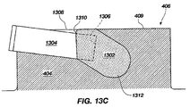
- plug or filler material 1302 may include a pocket 1310 formed therein and configured to receive a portion of cutting element 1304, as illustrated in FIG. 13C .
- pocket 1310 may be configured to fully surround a rear portion of cutting element 1304 abutting against face 1306.
- the broken lines shown in FIG. 13C illustrate pocket 1310 having a cutting element 1304 positioned therein, the plug or filler material 1302 fully surrounding a portion of cutting element 1304.
- the plug or filler material 1302 may be configured such that pocket 1310 may only partially surround cutting element 1304 at an area proximate the rear portion, as illustrated in FIG. 13C .
- plug or filler material 1302 may be configured to completely fill or only partially fill void 1308. Furthermore, some embodiments of plug or filler material 1302 may include a rear portion 1312 that is configured with a particular, selected shape. By way of non-limiting example only, FIG. 13C illustrates an embodiment having a dome-shaped rear portion 1312, the second recess 1316 being formed to have a complementary configuration to receive the plug or filler material 1302.
- FIG. 14 is a plan view of the face of an embodiment of an earth-boring rotary drill bit 1400 according to the present invention.
- the earth-boring rotary drill bit 1400 includes a bit body 1402 having a plurality of generally radially-projecting and longitudinally-extending wings or blades 1404, which are separated by junk slots 1406 extending from channels on the face of the bit body 1402.
- a plurality of primary PDC cutting elements 1408 are provided on each of the blades 1404 within cutting element pockets 414 ( FIG. 9 ).
- a plurality of secondary PDC cutting elements 1408' are also provided within cutting element pockets 414 on each of the blades 1404 rotationally behind the primary cutting elements 1408.
- cutters may be secured to the face of a bit body at relatively low back rake angles without encountering mechanical tool interference problems.
- earth-boring drilling tools such as the earth-boring rotary drill bit 1400 shown in FIG. 14 may be provided that are capable of drilling at increased rates of penetration relative to previously known drilling tools having machined cutter pockets, and similar to rates of penetration achieved using drilling tools having cutter pockets formed in a casting process (e.g., infiltration) used to fabricate so-called "matrix-type" bits.
- the cutting element pockets 414 FIG.
- the so-called "cone region" of one or more of the blades 1404 may be formed using methods described herein, and may be configured such that the PDC cutting elements 1408 disposed therein are oriented at backrake angles of less than about twenty degrees (20°).
- the PDC cutting elements 1408 in the cone region of one or more blades 1404 of the drill bit 1400 may be disposed at a back rake angle of between about ten degrees (10°) and about seventeen degrees (17°).
- body encompasses bodies of earth-boring rotary drill bits, as well as bodies of other earth-boring tools including, but not limited to, core bits, eccentric bits, bicenter bits, reamers, mills, roller cone bits, as well as other drilling and downhole tools.
Landscapes
- Engineering & Computer Science (AREA)
- Life Sciences & Earth Sciences (AREA)
- Geology (AREA)
- Mining & Mineral Resources (AREA)
- Mechanical Engineering (AREA)
- Physics & Mathematics (AREA)
- Environmental & Geological Engineering (AREA)
- Fluid Mechanics (AREA)
- General Life Sciences & Earth Sciences (AREA)
- Geochemistry & Mineralogy (AREA)
- Earth Drilling (AREA)
Claims (18)
- Procédé de formation d'un outil de forage terrestre (300), comprenant :la formation d'un corps (404) comprenant au moins une lame (406) ; etla formation d'au moins une poche pour élément de coupe (414) dans l'au moins une lame (406), comprenant :la formation d'un premier renfoncement (402) définissant au moins une partie d'une surface de paroi latérale (413) de l'au moins une poche pour élément de coupe (414) dans l'au moins une lame (406) ;la formation d'un deuxième renfoncement (416) dans la lame (406) en rotation derrière le premier renfoncement (402), au moins une partie du deuxième renfoncement (416) étant au moins partiellement recouverte par une surface extérieure (409) de la lame (406) ; etle procédé caractérisé par :le remplissage d'au moins une partie du deuxième renfoncement (416) avec un matériau de remplissage (902) pour former une totalité d'une surface de dos (906) de l'au moins une poche pour élément de coupe (414).
- Procédé selon la revendication 1, dans lequel la formation d'un premier renfoncement (402) comprend la formation d'un premier renfoncement (402) à partir d'au moins une d'une surface postérieure en rotation (410) et de la surface extérieure (409).
- Procédé selon la revendication 1, dans lequel la formation d'un deuxième renfoncement (416) dans la lame (406) en rotation derrière le premier renfoncement (402) comprend la formation du deuxième renfoncement (416) à partir d'au moins une d'une surface postérieure en rotation (410), de la surface extérieure (409), et d'une surface arrière de la poche pour élément de coupe (414).
- Procédé selon la revendication 1, dans lequel la formation d'un corps (404) comprenant au moins une lame (406) comprend :la prévision d'un mélange pulvérulent ;le pressage du mélange pulvérulent pour former un corps de trépan vert ; etle frittage au moins partiel du corps vert.
- Procédé selon la revendication 4, dans lequel au moins une de la formation d'un premier renfoncement (402) et de la formation d'un deuxième renfoncement (416) comprend au moins un d'un usinage du corps vert (404) et d'un usinage du corps (404) après frittage partiel du corps vert (404) en un état brun.
- Procédé selon la revendication 1, comprenant en outre la formation d'au moins une région d'épaulement (412) à une intersection entre le premier renfoncement (402) et le deuxième renfoncement (416) et la mise en butée d'une partie du matériau de remplissage contre l'au moins une région d'épaulement.
- Procédé selon l'une quelconque des revendications 1 ou 6, dans lequel le remplissage d'au moins une partie d'au moins le deuxième renfoncement (416) avec un matériau de remplissage (902) comprend le positionnement d'une structure pleine préformée à l'intérieur d'au moins une partie d'au moins le deuxième renfoncement (416).
- Procédé selon la revendication 7, dans lequel le remplissage d'au moins une partie d'au moins le deuxième renfoncement (416) avec un matériau de remplissage (902) comprend le remplissage d'au moins une partie du deuxième renfoncement (416) en rotation derrière la structure pleine préformée avec au moins un d'un matériau composite particules-matrice, d'un alliage de soudage, d'un alliage de brasage tendre, d'un alliage de brasage fort, et d'un matériau de surfaçage de renfort.
- Procédé selon la revendication 7, dans lequel le positionnement d'une structure pleine préformée à l'intérieur d'au moins une partie d'au moins le deuxième renfoncement (416) comprend le positionnement de la structure pleine préformée comprenant un compact de poudre vert ou une structure brune partiellement frittée à l'intérieur d'au moins une partie d'au moins le deuxième renfoncement (416).
- Procédé selon la revendication 9, comprenant en outre le cofrittage de la structure pleine préformée avec la lame (406) et la formation d'une liaison entre la structure pleine préformée et la lame (406).
- Outil de forage terrestre ayant un corps (404), comprenant :un premier renfoncement (402) formé dans le corps (404), une partie du corps (404) formant le premier renfoncement définissant une surface de paroi latérale (413) d'une poche pour élément de coupe (414), au moins une partie de la surface de paroi latérale ayant une forme de façon générale cylindrique centrée autour d'un axe longitudinal de la poche pour élément de coupe (414) ;un deuxième renfoncement (416) formé dans le corps (404), le deuxième renfoncement (416) ayant une extrémité avant en rotation adjacente à une extrémité arrière en rotation du premier renfoncement (402) et une extrémité arrière en rotation positionnée en-dessous d'une et au moins partiellement recouverte par une surface extérieure (409) du corps (404) ; etl'outil de forage terrestre caractérisé par :au moins une région d'épaulement (412) à une intersection entre le premier renfoncement (402) et le deuxième renfoncement (416) ; etun matériau de remplissage (902) disposé à l'intérieur d'au moins une partie du deuxième renfoncement (416) pour former au moins une partie d'une extrémité arrière en rotation de la poche pour élément de coupe (414), une partie du matériau de remplissage (902) venant buter sur l'au moins une région d'épaulement (412).
- Outil de forage terrestre selon la revendication 11, dans lequel l'extrémité arrière en rotation du deuxième renfoncement (416) coupe une surface arrière en rotation (410) du corps (404).
- Outil de forage terrestre selon la revendication 11, comprenant en outre un élément de coupe (1204) immobilisé à l'intérieur de la poche pour élément de coupe (414) et dans lequel le matériau de remplissage (902) comprend une poche (1310) formée à l'intérieur de celui-ci, la poche (1310) recevant au moins une partie de l'élément de coupe (1204).
- Outil de forage terrestre selon la revendication il, dans lequel le matériau de remplissage (902) remplit complètement le deuxième renfoncement (416).
- Outil de forage terrestre selon la revendication 11, dans lequel le matériau de remplissage (902) comprend une structure pleine préformée.
- Outil de forage terrestre selon la revendication 15, dans lequel la structure pleine préformée est cofrittée avec le corps (404) de trépan.
- Outil de forage terrestre selon la revendication 15, dans lequel la structure pleine préformée comprend un matériau composite particules-matrice.
- Outil de forage terrestre selon la revendication 11, dans lequel le corps (404) est de façon prédominante composé d'un matériau composite particules-matrice.
Applications Claiming Priority (2)
| Application Number | Priority Date | Filing Date | Title |
|---|---|---|---|
| US11/838,008 US7836980B2 (en) | 2007-08-13 | 2007-08-13 | Earth-boring tools having pockets for receiving cutting elements and methods for forming earth-boring tools including such pockets |
| PCT/US2008/072998 WO2009023706A1 (fr) | 2007-08-13 | 2008-08-13 | Outils de forage ayant des poches pour recevoir des éléments de coupe et procédés pour former des outils de forage comprenant de telles poches |
Publications (2)
| Publication Number | Publication Date |
|---|---|
| EP2181238A1 EP2181238A1 (fr) | 2010-05-05 |
| EP2181238B1 true EP2181238B1 (fr) | 2012-02-15 |
Family
ID=40104853
Family Applications (1)
| Application Number | Title | Priority Date | Filing Date |
|---|---|---|---|
| EP08797782A Active EP2181238B1 (fr) | 2007-08-13 | 2008-08-13 | Outils de forage ayant des poches pour recevoir des elements de coupe et procedes pour former des outils de forage comprenant de telles poches |
Country Status (5)
| Country | Link |
|---|---|
| US (2) | US7836980B2 (fr) |
| EP (1) | EP2181238B1 (fr) |
| AT (1) | ATE545765T1 (fr) |
| CA (1) | CA2695581C (fr) |
| WO (1) | WO2009023706A1 (fr) |
Families Citing this family (22)
| Publication number | Priority date | Publication date | Assignee | Title |
|---|---|---|---|---|
| US7776256B2 (en) | 2005-11-10 | 2010-08-17 | Baker Huges Incorporated | Earth-boring rotary drill bits and methods of manufacturing earth-boring rotary drill bits having particle-matrix composite bit bodies |
| US7807099B2 (en) | 2005-11-10 | 2010-10-05 | Baker Hughes Incorporated | Method for forming earth-boring tools comprising silicon carbide composite materials |
| US8770324B2 (en) | 2008-06-10 | 2014-07-08 | Baker Hughes Incorporated | Earth-boring tools including sinterbonded components and partially formed tools configured to be sinterbonded |
| US7841259B2 (en) * | 2006-12-27 | 2010-11-30 | Baker Hughes Incorporated | Methods of forming bit bodies |
| US7836980B2 (en) * | 2007-08-13 | 2010-11-23 | Baker Hughes Incorporated | Earth-boring tools having pockets for receiving cutting elements and methods for forming earth-boring tools including such pockets |
| US8261632B2 (en) | 2008-07-09 | 2012-09-11 | Baker Hughes Incorporated | Methods of forming earth-boring drill bits |
| US8355815B2 (en) * | 2009-02-12 | 2013-01-15 | Baker Hughes Incorporated | Methods, systems, and devices for manipulating cutting elements for earth-boring drill bits and tools |
| US8943663B2 (en) * | 2009-04-15 | 2015-02-03 | Baker Hughes Incorporated | Methods of forming and repairing cutting element pockets in earth-boring tools with depth-of-cut control features, and tools and structures formed by such methods |
| US8381844B2 (en) * | 2009-04-23 | 2013-02-26 | Baker Hughes Incorporated | Earth-boring tools and components thereof and related methods |
| US8701799B2 (en) * | 2009-04-29 | 2014-04-22 | Schlumberger Technology Corporation | Drill bit cutter pocket restitution |
| US8881850B2 (en) * | 2009-05-01 | 2014-11-11 | Smith International, Inc. | Cutter pocket design |
| US20120192680A1 (en) * | 2011-01-27 | 2012-08-02 | Baker Hughes Incorporated | Fabricated Mill Body with Blade Pockets for Insert Placement and Alignment |
| US9739097B2 (en) | 2011-04-26 | 2017-08-22 | Smith International, Inc. | Polycrystalline diamond compact cutters with conic shaped end |
| US20130263519A1 (en) * | 2011-12-29 | 2013-10-10 | Diamond Innovations, Inc. | Cutter assembly with at least one island and a method of manufacturing a cutter assembly |
| US20130318884A1 (en) * | 2011-12-29 | 2013-12-05 | Diamond Innovations, Inc. | Cutter assembly with at least one island and a method of manufacturing a cutter assembly |
| US9792432B2 (en) * | 2012-11-09 | 2017-10-17 | Nokia Technologies Oy | Method and apparatus for privacy-oriented code optimization |
| US9284789B2 (en) | 2013-03-01 | 2016-03-15 | Baker Hughes Incorporated | Methods for forming earth-boring tools having cutting elements mounted in cutting element pockets and tools formed by such methods |
| WO2015013354A1 (fr) * | 2013-07-25 | 2015-01-29 | Ulterra Drilling Technologies, L.P. | Élément de support d'outil de coupe |
| US10508503B2 (en) | 2016-09-23 | 2019-12-17 | Baker Hughes, A Ge Company, Llc | Cutting elements, earth-boring tools including the cutting elements, and methods of forming the earth-boring tools |
| US11066875B2 (en) * | 2018-03-02 | 2021-07-20 | Baker Hughes Holdings Llc | Earth-boring tools having pockets trailing rotationally leading faces of blades and having cutting elements disposed therein and related methods |
| US11505998B2 (en) * | 2020-10-15 | 2022-11-22 | Baker Hughes Oilfield Operations Llc | Earth-boring tool geometry and cutter placement and associated apparatus and methods |
| US20230075742A1 (en) * | 2021-09-03 | 2023-03-09 | Makino Inc. | Method for Manufacturing a Rotatable Tool Body to Minimize Cutting Insert Runout, a Tool Body Produced Therefrom, and a Method of Using Such a Tool Body |
Family Cites Families (27)
| Publication number | Priority date | Publication date | Assignee | Title |
|---|---|---|---|---|
| US2950524A (en) * | 1955-06-02 | 1960-08-30 | John A Bitterli | Means for mounting cutter bits or blades |
| US3459073A (en) * | 1967-06-12 | 1969-08-05 | Timken Roller Bearing Co | Rock bit assembly and bit insert assembly process |
| EP0084418A3 (fr) * | 1982-01-20 | 1983-08-10 | Unicorn Industries Limited | Trépan de forage et méthode d'utilisation |
| US4782903A (en) | 1987-01-28 | 1988-11-08 | Strange William S | Replaceable insert stud for drilling bits |
| US5111895A (en) * | 1988-03-11 | 1992-05-12 | Griffin Nigel D | Cutting elements for rotary drill bits |
| US5056382A (en) * | 1990-12-20 | 1991-10-15 | Smith International, Inc. | Matrix diamond drag bit with PCD cylindrical cutters |
| US5558170A (en) | 1992-12-23 | 1996-09-24 | Baroid Technology, Inc. | Method and apparatus for improving drill bit stability |
| US5678645A (en) * | 1995-11-13 | 1997-10-21 | Baker Hughes Incorporated | Mechanically locked cutters and nozzles |
| GB9603402D0 (en) | 1996-02-17 | 1996-04-17 | Camco Drilling Group Ltd | Improvements in or relating to rotary drill bits |
| GB9906114D0 (en) | 1999-03-18 | 1999-05-12 | Camco Int Uk Ltd | A method of applying a wear-resistant layer to a surface of a downhole component |
| US6302224B1 (en) * | 1999-05-13 | 2001-10-16 | Halliburton Energy Services, Inc. | Drag-bit drilling with multi-axial tooth inserts |
| US6349780B1 (en) | 2000-08-11 | 2002-02-26 | Baker Hughes Incorporated | Drill bit with selectively-aggressive gage pads |
| US7070011B2 (en) * | 2003-11-17 | 2006-07-04 | Baker Hughes Incorporated | Steel body rotary drill bits including support elements affixed to the bit body at least partially defining cutter pocket recesses |
| US20050183893A1 (en) * | 2004-01-13 | 2005-08-25 | Sandvik Ab | Indexable cutting inserts and methods for producing the same |
| US7373997B2 (en) | 2005-02-18 | 2008-05-20 | Smith International, Inc. | Layered hardfacing, durable hardfacing for drill bits |
| US7533739B2 (en) | 2005-06-09 | 2009-05-19 | Us Synthetic Corporation | Cutting element apparatuses and drill bits so equipped |
| US7776256B2 (en) | 2005-11-10 | 2010-08-17 | Baker Huges Incorporated | Earth-boring rotary drill bits and methods of manufacturing earth-boring rotary drill bits having particle-matrix composite bit bodies |
| US7703555B2 (en) | 2005-09-09 | 2010-04-27 | Baker Hughes Incorporated | Drilling tools having hardfacing with nickel-based matrix materials and hard particles |
| US7802495B2 (en) | 2005-11-10 | 2010-09-28 | Baker Hughes Incorporated | Methods of forming earth-boring rotary drill bits |
| WO2007098159A2 (fr) * | 2006-02-23 | 2007-08-30 | Baker Hughes Incorporated | Insert d'élément de coupe de dispositifs de coupe de réserve dans des trépans rotatifs, trépans rotatifs équipés d'un tel insert, et procédés de fabrication correspondants |
| US20080223622A1 (en) * | 2007-03-13 | 2008-09-18 | Duggan James L | Earth-boring tools having pockets for receiving cutting elements therein and methods of forming such pockets and earth-boring tools |
| US20090000827A1 (en) * | 2007-06-26 | 2009-01-01 | Baker Hughes Incorporated | Cutter pocket having reduced stress concentration |
| US20090008155A1 (en) * | 2007-07-02 | 2009-01-08 | Baker Hughes Incorporated | Pdc cutter with oval cross-section |
| US8011456B2 (en) * | 2007-07-18 | 2011-09-06 | Baker Hughes Incorporated | Rotationally indexable cutting elements and drill bits therefor |
| US8268452B2 (en) * | 2007-07-31 | 2012-09-18 | Baker Hughes Incorporated | Bonding agents for improved sintering of earth-boring tools, methods of forming earth-boring tools and resulting structures |
| US7836980B2 (en) * | 2007-08-13 | 2010-11-23 | Baker Hughes Incorporated | Earth-boring tools having pockets for receiving cutting elements and methods for forming earth-boring tools including such pockets |
| US8079431B1 (en) * | 2009-03-17 | 2011-12-20 | Us Synthetic Corporation | Drill bit having rotational cutting elements and method of drilling |
-
2007
- 2007-08-13 US US11/838,008 patent/US7836980B2/en active Active
-
2008
- 2008-08-13 CA CA2695581A patent/CA2695581C/fr active Active
- 2008-08-13 EP EP08797782A patent/EP2181238B1/fr active Active
- 2008-08-13 WO PCT/US2008/072998 patent/WO2009023706A1/fr active Application Filing
- 2008-08-13 AT AT08797782T patent/ATE545765T1/de active
-
2010
- 2010-10-20 US US12/908,234 patent/US8307739B2/en active Active
Also Published As
| Publication number | Publication date |
|---|---|
| ATE545765T1 (de) | 2012-03-15 |
| CA2695581A1 (fr) | 2009-02-19 |
| CA2695581C (fr) | 2013-07-16 |
| US8307739B2 (en) | 2012-11-13 |
| US7836980B2 (en) | 2010-11-23 |
| US20110030509A1 (en) | 2011-02-10 |
| WO2009023706A1 (fr) | 2009-02-19 |
| EP2181238A1 (fr) | 2010-05-05 |
| US20090044663A1 (en) | 2009-02-19 |
Similar Documents
| Publication | Publication Date | Title |
|---|---|---|
| EP2181238B1 (fr) | Outils de forage ayant des poches pour recevoir des elements de coupe et procedes pour former des outils de forage comprenant de telles poches | |
| EP2129860B1 (fr) | Outils de forage présentant des poches destinées à recevoir des éléments de découpe à l'intérieur et procédés de formation de ces poches et outils de forage | |
| EP1989391B1 (fr) | Insert d'élément de coupe de dispositifs de coupe de réserve dans des trépans rotatifs, trépans rotatifs équipés d'un tel insert, et procédés de fabrication correspondants | |
| US10221628B2 (en) | Methods of repairing cutting element pockets in earth-boring tools with depth-of-cut control features | |
| EP3540173A1 (fr) | Éléments de coupe mis en forme pour outils de forage, outils de forage comprenant de tels éléments de coupe et procédés associés | |
| WO2013119930A1 (fr) | Éléments de coupe profilés pour outils de forage et outils de forage comprenant lesdits éléments de coupe | |
| EP2497895B1 (fr) | Procédés de forage excentré | |
| US10107044B2 (en) | Methods of forming and repairing earth-boring tools including replaceable cutting structures | |
| US20090032309A1 (en) | Sleeve structures for earth-boring tools, tools including sleeve structures and methods of forming such tools | |
| WO2011059685A2 (fr) | Éléments de coupe de réserve sur outil de forage terrestre non concentrique et procédés associés | |
| US8047309B2 (en) | Passive and active up-drill features on fixed cutter earth-boring tools and related systems and methods | |
| US20180135357A1 (en) | Attachment of tsp diamond ring using brazing and mechanical locking | |
| US20230151698A1 (en) | Earth boring tools including brazed cutting elements and related methods |
Legal Events
| Date | Code | Title | Description |
|---|---|---|---|
| PUAI | Public reference made under article 153(3) epc to a published international application that has entered the european phase |
Free format text: ORIGINAL CODE: 0009012 |
|
| 17P | Request for examination filed |
Effective date: 20100211 |
|
| AK | Designated contracting states |
Kind code of ref document: A1 Designated state(s): AT BE BG CH CY CZ DE DK EE ES FI FR GB GR HR HU IE IS IT LI LT LU LV MC MT NL NO PL PT RO SE SI SK TR |
|
| AX | Request for extension of the european patent |
Extension state: AL BA MK RS |
|
| 17Q | First examination report despatched |
Effective date: 20100607 |
|
| DAX | Request for extension of the european patent (deleted) | ||
| GRAP | Despatch of communication of intention to grant a patent |
Free format text: ORIGINAL CODE: EPIDOSNIGR1 |
|
| GRAS | Grant fee paid |
Free format text: ORIGINAL CODE: EPIDOSNIGR3 |
|
| GRAA | (expected) grant |
Free format text: ORIGINAL CODE: 0009210 |
|
| AK | Designated contracting states |
Kind code of ref document: B1 Designated state(s): AT BE BG CH CY CZ DE DK EE ES FI FR GB GR HR HU IE IS IT LI LT LU LV MC MT NL NO PL PT RO SE SI SK TR |
|
| REG | Reference to a national code |
Ref country code: CH Ref legal event code: EP Ref country code: GB Ref legal event code: FG4D |
|
| REG | Reference to a national code |
Ref country code: IE Ref legal event code: FG4D |
|
| REG | Reference to a national code |
Ref country code: AT Ref legal event code: REF Ref document number: 545765 Country of ref document: AT Kind code of ref document: T Effective date: 20120315 |
|
| REG | Reference to a national code |
Ref country code: DE Ref legal event code: R096 Ref document number: 602008013474 Country of ref document: DE Effective date: 20120412 |
|
| REG | Reference to a national code |
Ref country code: NL Ref legal event code: VDEP Effective date: 20120215 |
|
| LTIE | Lt: invalidation of european patent or patent extension |
Effective date: 20120215 |
|
| PG25 | Lapsed in a contracting state [announced via postgrant information from national office to epo] |
Ref country code: HR Free format text: LAPSE BECAUSE OF FAILURE TO SUBMIT A TRANSLATION OF THE DESCRIPTION OR TO PAY THE FEE WITHIN THE PRESCRIBED TIME-LIMIT Effective date: 20120215 Ref country code: NL Free format text: LAPSE BECAUSE OF FAILURE TO SUBMIT A TRANSLATION OF THE DESCRIPTION OR TO PAY THE FEE WITHIN THE PRESCRIBED TIME-LIMIT Effective date: 20120215 Ref country code: NO Free format text: LAPSE BECAUSE OF FAILURE TO SUBMIT A TRANSLATION OF THE DESCRIPTION OR TO PAY THE FEE WITHIN THE PRESCRIBED TIME-LIMIT Effective date: 20120515 Ref country code: IS Free format text: LAPSE BECAUSE OF FAILURE TO SUBMIT A TRANSLATION OF THE DESCRIPTION OR TO PAY THE FEE WITHIN THE PRESCRIBED TIME-LIMIT Effective date: 20120615 Ref country code: LT Free format text: LAPSE BECAUSE OF FAILURE TO SUBMIT A TRANSLATION OF THE DESCRIPTION OR TO PAY THE FEE WITHIN THE PRESCRIBED TIME-LIMIT Effective date: 20120215 |
|
| PG25 | Lapsed in a contracting state [announced via postgrant information from national office to epo] |
Ref country code: GR Free format text: LAPSE BECAUSE OF FAILURE TO SUBMIT A TRANSLATION OF THE DESCRIPTION OR TO PAY THE FEE WITHIN THE PRESCRIBED TIME-LIMIT Effective date: 20120516 Ref country code: PT Free format text: LAPSE BECAUSE OF FAILURE TO SUBMIT A TRANSLATION OF THE DESCRIPTION OR TO PAY THE FEE WITHIN THE PRESCRIBED TIME-LIMIT Effective date: 20120615 Ref country code: LV Free format text: LAPSE BECAUSE OF FAILURE TO SUBMIT A TRANSLATION OF THE DESCRIPTION OR TO PAY THE FEE WITHIN THE PRESCRIBED TIME-LIMIT Effective date: 20120215 Ref country code: BE Free format text: LAPSE BECAUSE OF FAILURE TO SUBMIT A TRANSLATION OF THE DESCRIPTION OR TO PAY THE FEE WITHIN THE PRESCRIBED TIME-LIMIT Effective date: 20120215 Ref country code: FI Free format text: LAPSE BECAUSE OF FAILURE TO SUBMIT A TRANSLATION OF THE DESCRIPTION OR TO PAY THE FEE WITHIN THE PRESCRIBED TIME-LIMIT Effective date: 20120215 Ref country code: PL Free format text: LAPSE BECAUSE OF FAILURE TO SUBMIT A TRANSLATION OF THE DESCRIPTION OR TO PAY THE FEE WITHIN THE PRESCRIBED TIME-LIMIT Effective date: 20120215 |
|
| REG | Reference to a national code |
Ref country code: AT Ref legal event code: MK05 Ref document number: 545765 Country of ref document: AT Kind code of ref document: T Effective date: 20120215 |
|
| PG25 | Lapsed in a contracting state [announced via postgrant information from national office to epo] |
Ref country code: CY Free format text: LAPSE BECAUSE OF FAILURE TO SUBMIT A TRANSLATION OF THE DESCRIPTION OR TO PAY THE FEE WITHIN THE PRESCRIBED TIME-LIMIT Effective date: 20120215 |
|
| PG25 | Lapsed in a contracting state [announced via postgrant information from national office to epo] |
Ref country code: SI Free format text: LAPSE BECAUSE OF FAILURE TO SUBMIT A TRANSLATION OF THE DESCRIPTION OR TO PAY THE FEE WITHIN THE PRESCRIBED TIME-LIMIT Effective date: 20120215 Ref country code: DK Free format text: LAPSE BECAUSE OF FAILURE TO SUBMIT A TRANSLATION OF THE DESCRIPTION OR TO PAY THE FEE WITHIN THE PRESCRIBED TIME-LIMIT Effective date: 20120215 Ref country code: RO Free format text: LAPSE BECAUSE OF FAILURE TO SUBMIT A TRANSLATION OF THE DESCRIPTION OR TO PAY THE FEE WITHIN THE PRESCRIBED TIME-LIMIT Effective date: 20120215 Ref country code: EE Free format text: LAPSE BECAUSE OF FAILURE TO SUBMIT A TRANSLATION OF THE DESCRIPTION OR TO PAY THE FEE WITHIN THE PRESCRIBED TIME-LIMIT Effective date: 20120215 Ref country code: SE Free format text: LAPSE BECAUSE OF FAILURE TO SUBMIT A TRANSLATION OF THE DESCRIPTION OR TO PAY THE FEE WITHIN THE PRESCRIBED TIME-LIMIT Effective date: 20120215 Ref country code: CZ Free format text: LAPSE BECAUSE OF FAILURE TO SUBMIT A TRANSLATION OF THE DESCRIPTION OR TO PAY THE FEE WITHIN THE PRESCRIBED TIME-LIMIT Effective date: 20120215 |
|
| PG25 | Lapsed in a contracting state [announced via postgrant information from national office to epo] |
Ref country code: SK Free format text: LAPSE BECAUSE OF FAILURE TO SUBMIT A TRANSLATION OF THE DESCRIPTION OR TO PAY THE FEE WITHIN THE PRESCRIBED TIME-LIMIT Effective date: 20120215 |
|
| PLBE | No opposition filed within time limit |
Free format text: ORIGINAL CODE: 0009261 |
|
| STAA | Information on the status of an ep patent application or granted ep patent |
Free format text: STATUS: NO OPPOSITION FILED WITHIN TIME LIMIT |
|
| 26N | No opposition filed |
Effective date: 20121116 |
|
| PG25 | Lapsed in a contracting state [announced via postgrant information from national office to epo] |
Ref country code: AT Free format text: LAPSE BECAUSE OF FAILURE TO SUBMIT A TRANSLATION OF THE DESCRIPTION OR TO PAY THE FEE WITHIN THE PRESCRIBED TIME-LIMIT Effective date: 20120215 |
|
| REG | Reference to a national code |
Ref country code: DE Ref legal event code: R097 Ref document number: 602008013474 Country of ref document: DE Effective date: 20121116 |
|
| REG | Reference to a national code |
Ref country code: CH Ref legal event code: PL |
|
| PG25 | Lapsed in a contracting state [announced via postgrant information from national office to epo] |
Ref country code: MC Free format text: LAPSE BECAUSE OF NON-PAYMENT OF DUE FEES Effective date: 20120831 |
|
| PG25 | Lapsed in a contracting state [announced via postgrant information from national office to epo] |
Ref country code: LI Free format text: LAPSE BECAUSE OF NON-PAYMENT OF DUE FEES Effective date: 20120831 Ref country code: ES Free format text: LAPSE BECAUSE OF FAILURE TO SUBMIT A TRANSLATION OF THE DESCRIPTION OR TO PAY THE FEE WITHIN THE PRESCRIBED TIME-LIMIT Effective date: 20120526 Ref country code: CH Free format text: LAPSE BECAUSE OF NON-PAYMENT OF DUE FEES Effective date: 20120831 |
|
| PG25 | Lapsed in a contracting state [announced via postgrant information from national office to epo] |
Ref country code: BG Free format text: LAPSE BECAUSE OF FAILURE TO SUBMIT A TRANSLATION OF THE DESCRIPTION OR TO PAY THE FEE WITHIN THE PRESCRIBED TIME-LIMIT Effective date: 20120515 |
|
| PG25 | Lapsed in a contracting state [announced via postgrant information from national office to epo] |
Ref country code: MT Free format text: LAPSE BECAUSE OF FAILURE TO SUBMIT A TRANSLATION OF THE DESCRIPTION OR TO PAY THE FEE WITHIN THE PRESCRIBED TIME-LIMIT Effective date: 20120215 |
|
| PG25 | Lapsed in a contracting state [announced via postgrant information from national office to epo] |
Ref country code: TR Free format text: LAPSE BECAUSE OF FAILURE TO SUBMIT A TRANSLATION OF THE DESCRIPTION OR TO PAY THE FEE WITHIN THE PRESCRIBED TIME-LIMIT Effective date: 20120215 |
|
| PG25 | Lapsed in a contracting state [announced via postgrant information from national office to epo] |
Ref country code: LU Free format text: LAPSE BECAUSE OF NON-PAYMENT OF DUE FEES Effective date: 20120813 |
|
| PG25 | Lapsed in a contracting state [announced via postgrant information from national office to epo] |
Ref country code: HU Free format text: LAPSE BECAUSE OF FAILURE TO SUBMIT A TRANSLATION OF THE DESCRIPTION OR TO PAY THE FEE WITHIN THE PRESCRIBED TIME-LIMIT Effective date: 20080813 |
|
| PGFP | Annual fee paid to national office [announced via postgrant information from national office to epo] |
Ref country code: IE Payment date: 20140812 Year of fee payment: 7 Ref country code: DE Payment date: 20140806 Year of fee payment: 7 |
|
| PGFP | Annual fee paid to national office [announced via postgrant information from national office to epo] |
Ref country code: FR Payment date: 20140808 Year of fee payment: 7 Ref country code: GB Payment date: 20140813 Year of fee payment: 7 |
|
| REG | Reference to a national code |
Ref country code: DE Ref legal event code: R119 Ref document number: 602008013474 Country of ref document: DE |
|
| GBPC | Gb: european patent ceased through non-payment of renewal fee |
Effective date: 20150813 |
|
| REG | Reference to a national code |
Ref country code: IE Ref legal event code: MM4A |
|
| REG | Reference to a national code |
Ref country code: FR Ref legal event code: ST Effective date: 20160429 |
|
| PG25 | Lapsed in a contracting state [announced via postgrant information from national office to epo] |
Ref country code: GB Free format text: LAPSE BECAUSE OF NON-PAYMENT OF DUE FEES Effective date: 20150813 Ref country code: DE Free format text: LAPSE BECAUSE OF NON-PAYMENT OF DUE FEES Effective date: 20160301 Ref country code: IE Free format text: LAPSE BECAUSE OF NON-PAYMENT OF DUE FEES Effective date: 20150813 |
|
| PG25 | Lapsed in a contracting state [announced via postgrant information from national office to epo] |
Ref country code: FR Free format text: LAPSE BECAUSE OF NON-PAYMENT OF DUE FEES Effective date: 20150831 |
|
| PGFP | Annual fee paid to national office [announced via postgrant information from national office to epo] |
Ref country code: IT Payment date: 20220720 Year of fee payment: 15 |
|
| P01 | Opt-out of the competence of the unified patent court (upc) registered |
Effective date: 20230526 |