EP2181017B1 - Anti-whiplash backdrive prevention system - Google Patents
Anti-whiplash backdrive prevention system Download PDFInfo
- Publication number
- EP2181017B1 EP2181017B1 EP07804901A EP07804901A EP2181017B1 EP 2181017 B1 EP2181017 B1 EP 2181017B1 EP 07804901 A EP07804901 A EP 07804901A EP 07804901 A EP07804901 A EP 07804901A EP 2181017 B1 EP2181017 B1 EP 2181017B1
- Authority
- EP
- European Patent Office
- Prior art keywords
- clearance
- release mechanism
- movable part
- head restraint
- stationary part
- Prior art date
- Legal status (The legal status is an assumption and is not a legal conclusion. Google has not performed a legal analysis and makes no representation as to the accuracy of the status listed.)
- Not-in-force
Links
Images


Classifications
-
- B—PERFORMING OPERATIONS; TRANSPORTING
- B60—VEHICLES IN GENERAL
- B60N—SEATS SPECIALLY ADAPTED FOR VEHICLES; VEHICLE PASSENGER ACCOMMODATION NOT OTHERWISE PROVIDED FOR
- B60N2/00—Seats specially adapted for vehicles; Arrangement or mounting of seats in vehicles
- B60N2/80—Head-rests
- B60N2/888—Head-rests with arrangements for protecting against abnormal g-forces, e.g. by displacement of the head-rest
Definitions
- the present invention relates to an anti-whiplash system for the use in vehicle seats.
- whiplash injuries have been linked to a too large gap between the head restraint of the vehicle seat and an occupant's head.
- the occupant's body In case of a rear-end collision the occupant's body is accelerated forward whereas the head of the occupant accelerates in the gap backwards relative to the vehicle by virtue of its inertia.
- Head restraint systems reducing the gap between the head restraint of the vehicle seat and an occupant's head in case of an accident are for example known from US 6,805,411 B2 , US 7,111,901 B2 or US 2001/0040396 A1 .
- US 6,805,411 B2 describes a neck rest for the seats of automobiles with a pivotably supported movable cushion member. Upon actuation of the comprised actuation means the cushion member is moved into an actuated position towards the head of a person seating on the seat. Stop means prevent the cushion member from pivoting back when it has attained its actuated position.
- the head restraint described in US 7,111,901 B2 comprises a cylinder mounted on the main head restraint body that moves a head-engaging member along a slide displaceable in a straight line axially along the cylinder in an outer activated position upon actuation in case of an accident.
- Return-lock means comprising a locking tooth and a countertooth prevent the head-engaging member from returning back towards its initial position.
- the object of the present invention to provide for a simple and inexpensive anti-whiplash system for the use in vehicle seats with an active head restraint.
- the anti-whiplash system should comprise means for a continuous backdrive prevention such that the head restraint is prevented from returning out of any activated position to provide a secure head support at any moment during the activation process.
- the movable wedging body is preloaded by a spring. More preferably, the movable wedging body is urged to gradually rotate into the clearance when the release mechanism is released in order to prevent the movable part of the head restraint from moving back. Thereby, the wedging body gradually fills the clearance as it opens up between the movable part and the stationary part of the release mechanism and abuts against the movable part and against the stationary part.
- the movable wedging body is an essentially wedge-shaped body.
- the essentially wedge-shaped body may comprise a sloped surface creating an increased thickness of the body from the small width portion via the intermediate increasing width portion to the large width portion.
- the wedge-shaped body may be oriented with its apex or small width portion towards the clearance and may slide into the clearance as it opens up.
- the wedging body is rotatable and comprises a helically shaped surface portion winding up from the small width portion via the intermediate increasing width portion.to the large width portion.
- the wedging body may essentially have the shape of a disc segment that is rotatable about its central axis.
- the disc segment may comprise one surface having essentially the shape of a circle segment that winds up from the small width portion via the intermediate increasing width portion to the large width portion following a helix.
- the wedging body may have the shape of a segment of a ring, the ring having an annular surface winding up from the small width portion via the intermediate increasing width portion to the large width portion.
- the release mechanism is arranged to pivot the head restraint forward with respect to the backrest of the vehicle seat such that an angular-shaped clearance between the movable part and the stationary part opens up near the pivot axis when the release mechanism is deployed and the movable wedging body is urged to move into the angular-shaped clearance.
- the movable part comprises a head engaging member and at least one rotatable cam attached to the head engaging member.
- the rotatable cam is also rotatably attached to the stationary part, such that the gap between the head engaging member and the stationary part is increased upon rotation of the cam.
- the cam comprises an extension such that the extension follows a circular path away from the stationary part when the cam rotates, such that the clearance opens up between the extension of the cam and the stationary part.
- the movable wedging body is preloaded to move into the clearance as it opens up to thereby abut against the extension of the cam and against the stationary part in order to prevent the movable part of the head restraint from moving back.
- the release mechanism comprises a returning mechanism for returning the head restraint into its initial position after the release mechanism has been released, wherein the returning mechanism comprises means for returning the movable wedging body back into its initial preloaded position.
- the returning mechanism can be deployed by pressing a button or turning a rotary handle.
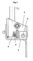
- the active head restraint 1 shown in figures 1 to 3 comprises a release mechanism for reducing the gap between an occupant's head and the head restraint in case of an accident.
- the head-engaging member 2 is mounted on a cassette comprising essentially a movable part 5 and a stationary part 3.
- the stationary part 3 is mounted on the backrest of a vehicle seat (not shown).
- the movable part 5 is connected pivotably about an across-vehicle axis A to the stationary part 3.
- the movable part 5 pivots forward and moves the attached head-engaging member 2 essentially towards an occupant's head (not shown) such that the gap between the head restraint and an occupant's head is reduced.
- a wedging body 4 connected rotatably about a vertical axis to the stationary part 3 of the cassette.
- a spring 6 the wedging body 4 is preloaded and abuts with its small width portion against the movable part 5 adjacent to the clearance between the movable part 5 and the stationary part 3 that open up upon a forward pivot movement of the movable part 5 about the cross-vehicle axis A during an activation process.
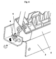
- Figures 4 and 5 show the active head restraint 1 in an activated state where the gap between an occupant's head and the head restraint is reduced by a forward pivot movement of the movable part 5 about the cross-vehicle axis A.
- a clearance in form of an angle 7 opens up.
- the clearance is filled gradually by the preloaded movable wedging body 4 that rotates about a vertical axis into the clearance and prevents the movable part 5 of the head restraint 1 from moving back.
- a second embodiment of the invention is shown in figures 6 to 12 .
- the head-engaging member 2 is connected to at least one rotatable cam 8 such that the gap between an occupant's head and the head-engaging member 2 is reduced upon a concerted rotation of the cam 8 about an across-vehicle axis.
- the preloaded movable wedging body 4 is urged to move into a clearance that opens up upon rotation of the cam 8 in order to prevent the cams 8 from rotating back.
- the cam 8 comprises an extension 9 provided on the surface of the cam 8 such that the extension 9 follows a circular path away from the stationary part 3 when the cam 8 rotates about an across-vehicle axis A upon actuation of the anti-whiplash system.
- the clearance opens up between the extension 9 on the cam 8 and the stationary part 3 of the release mechanism.
- the wedging body 4 is connected rotatably about an alongside-vehicle axis to the stationary part 3.
- the wedging body 4 is preloaded and abuts with its small width portion against the extension 9 of the cam 8.
- the clearance between the extension 9 of the cam 8 and the stationary part 3 opens up upon a rotation of the cam 8 about an across-vehicle axis A during an activation process.
- the clearance is large enough to engage the small width portion of the wedging body 4 the wedging body 4 rotates about an alongside-vehicle axis such that it fills the clearance and prevents the cam 8 from moving back.
- the cam 8 has reached the activated position as shown in figures 7 , 9 , 11 and 12 the clearance is maximally opened up and the wedging body 4 has reached its final blocking position.
Landscapes
- Engineering & Computer Science (AREA)
- Aviation & Aerospace Engineering (AREA)
- Transportation (AREA)
- Mechanical Engineering (AREA)
- Seats For Vehicles (AREA)
Abstract
Description
- The present invention relates to an anti-whiplash system for the use in vehicle seats.
- It is important for the safety in vehicles to reduce the Neck-Injury-Criterion level in case of crashes, in particular of a rear-end impact accident. Rear-end collisions are rarely fatal, but they give rise to fully one quarter of all personal injuries, often with permanent impairment, and to extended sick-leave and inability to work. In addition to the human suffering, these injuries account in many countries for more than 50% of all insurance claims and costs for societies for personal injuries sustained by car occupants.
- These whiplash injuries have been linked to a too large gap between the head restraint of the vehicle seat and an occupant's head. In case of a rear-end collision the occupant's body is accelerated forward whereas the head of the occupant accelerates in the gap backwards relative to the vehicle by virtue of its inertia. Thus, the closer the gap is the less the head is dangerously accelerated backwards relative to the vehicle.
- Head restraint systems reducing the gap between the head restraint of the vehicle seat and an occupant's head in case of an accident are for example known from
US 6,805,411 B2 ,US 7,111,901 B2 orUS 2001/0040396 A1 . -
US 6,805,411 B2 describes a neck rest for the seats of automobiles with a pivotably supported movable cushion member. Upon actuation of the comprised actuation means the cushion member is moved into an actuated position towards the head of a person seating on the seat. Stop means prevent the cushion member from pivoting back when it has attained its actuated position. - The head restraint described in
US 7,111,901 B2 comprises a cylinder mounted on the main head restraint body that moves a head-engaging member along a slide displaceable in a straight line axially along the cylinder in an outer activated position upon actuation in case of an accident. Return-lock means comprising a locking tooth and a countertooth prevent the head-engaging member from returning back towards its initial position. -
DE 10 2004 0164 74 B3 discloses an anti-whiplash system according to the preamble ofclaim 1. - All the above-mentioned anti-whiplash systems known from the prior art have the disadvantage that they are rather complex. The complex mechanical setup therein is relatively expensive with regard to production costs. Especially the known backdrive prevention systems as a vital feature of an anti-whiplash system exhibit a restricted range of use. The backdrive prevention systems known from the prior art are restricted to lock the deployed head restraint in predefined positions if not just in the activated position.
- It is therefore the object of the present invention to provide for a simple and inexpensive anti-whiplash system for the use in vehicle seats with an active head restraint. Furthermore, the anti-whiplash system should comprise means for a continuous backdrive prevention such that the head restraint is prevented from returning out of any activated position to provide a secure head support at any moment during the activation process.
- This object is achieved according to the present invention by the features of
claim 1. Preferred embodiments of the invention are subject of the dependent claims. - According to the present invention an anti-whiplash system for the use in vehicle seats comprising a head restraint mounted on the backrest of a vehicle seat is provided, wherein the head restraint comprises a release mechanism for reducing the gap between an occupant's head and the head restraint in case of an accident, said release mechanism comprises a movable part and a stationary part, wherein a clearance between the movable part and the stationary part opens up when the release mechanism is released, characterised in that in addition to the release mechanism, a wedging body is provided having a small width portion and a large width portion and an intermediate increasing width portion, wherein the wedging body points with its small width portion towards the clearance between the movable part and the stationary part, and in that the wedging body is movable and preloaded to move into the clearance as it opens up to thereby abut against the the movable part and against the stationary part in order to prevent the movable part of the head restraint from moving back.
- Preferably, the movable wedging body is preloaded by a spring. More preferably, the movable wedging body is urged to gradually rotate into the clearance when the release mechanism is released in order to prevent the movable part of the head restraint from moving back. Thereby, the wedging body gradually fills the clearance as it opens up between the movable part and the stationary part of the release mechanism and abuts against the movable part and against the stationary part.
- Preferably, the movable wedging body is an essentially wedge-shaped body. The essentially wedge-shaped body may comprise a sloped surface creating an increased thickness of the body from the small width portion via the intermediate increasing width portion to the large width portion. The wedge-shaped body may be oriented with its apex or small width portion towards the clearance and may slide into the clearance as it opens up.
- More preferably, the wedging body is rotatable and comprises a helically shaped surface portion winding up from the small width portion via the intermediate increasing width portion.to the large width portion. The wedging body may essentially have the shape of a disc segment that is rotatable about its central axis. The disc segment may comprise one surface having essentially the shape of a circle segment that winds up from the small width portion via the intermediate increasing width portion to the large width portion following a helix. Alternatively, the wedging body may have the shape of a segment of a ring, the ring having an annular surface winding up from the small width portion via the intermediate increasing width portion to the large width portion.
- In a first preferred embodiment of the invention the release mechanism is arranged to pivot the head restraint forward with respect to the backrest of the vehicle seat such that an angular-shaped clearance between the movable part and the stationary part opens up near the pivot axis when the release mechanism is deployed and the movable wedging body is urged to move into the angular-shaped clearance.
- In a second preferred embodiment of the invention the movable part comprises a head engaging member and at least one rotatable cam attached to the head engaging member. The rotatable cam is also rotatably attached to the stationary part, such that the gap between the head engaging member and the stationary part is increased upon rotation of the cam. The cam comprises an extension such that the extension follows a circular path away from the stationary part when the cam rotates, such that the clearance opens up between the extension of the cam and the stationary part. The movable wedging body is preloaded to move into the clearance as it opens up to thereby abut against the extension of the cam and against the stationary part in order to prevent the movable part of the head restraint from moving back.
- Preferably, the release mechanism comprises a returning mechanism for returning the head restraint into its initial position after the release mechanism has been released, wherein the returning mechanism comprises means for returning the movable wedging body back into its initial preloaded position. The returning mechanism can be deployed by pressing a button or turning a rotary handle.
- It should be understood that apart from the embodiments described herein other configurations of the inventive anti-whiplash system are possible. The invention is applicable in any configuration where a clearance opens up in the release mechanism.
- In the following, a preferred embodiment of the invention is described in detail with references to the accompanying
figures 1 to 12 , wherefigures 1 to 5 refer to a first embodiment of the invention andfigures 6 to 12 refer to a second embodiment of the invention. -
Figure 1 shows a perspective view of a head restraint provided with an inventive anti-whiplash system in an initial state. -
Figure 2 shows a detailed perspective view of the backdrive prevention system in an initial state. -
Figure 3 shows a detailed side view of the backdrive prevention system in an initial state. -
Figure 4 shows a detailed perspective view of the backdrive prevention system in an activated state. -
Figure 5 shows a detailed side view of the backdrive prevention system in an activated state. -
Figure 6 shows a side view of a head restraint provided with an inventive anti-whiplash system in an initial state. -
Figure 7 shows a side view of a head restraint provided with an inventive anti-whiplash system in an activated state. -
Figure 8 shows a detailed perspective view of the backdrive prevention system in an initial state. -
Figure 9 shows a detailed perspective view of the backdrive prevention system in an activated state. -
Figure 10 shows a detailed side view of a head restraint provided with an inventive anti-whiplash system in an initial state. -
Figure 11 shows a detailed side view of a head restraint provided with an inventive anti-whiplash system in an activated state. -
Figure 12 shows a top view of a head restraint provided with an inventive anti-whiplash system in an activated state. - The
active head restraint 1 shown infigures 1 to 3 comprises a release mechanism for reducing the gap between an occupant's head and the head restraint in case of an accident. The head-engaging member 2 is mounted on a cassette comprising essentially amovable part 5 and astationary part 3. Thestationary part 3 is mounted on the backrest of a vehicle seat (not shown). Themovable part 5 is connected pivotably about an across-vehicle axis A to thestationary part 3. Upon activation of the anti-whiplash system themovable part 5 pivots forward and moves the attached head-engaging member 2 essentially towards an occupant's head (not shown) such that the gap between the head restraint and an occupant's head is reduced. At one or both lateral sides of the cassette there is awedging body 4 connected rotatably about a vertical axis to thestationary part 3 of the cassette. By means of aspring 6 thewedging body 4 is preloaded and abuts with its small width portion against themovable part 5 adjacent to the clearance between themovable part 5 and thestationary part 3 that open up upon a forward pivot movement of themovable part 5 about the cross-vehicle axis A during an activation process. -
Figures 4 and5 show theactive head restraint 1 in an activated state where the gap between an occupant's head and the head restraint is reduced by a forward pivot movement of themovable part 5 about the cross-vehicle axis A. Upon such a forward pivot movement a clearance in form of anangle 7 opens up. The clearance is filled gradually by the preloadedmovable wedging body 4 that rotates about a vertical axis into the clearance and prevents themovable part 5 of the head restraint 1 from moving back. - A second embodiment of the invention is shown in
figures 6 to 12 . In this embodiment the head-engagingmember 2 is connected to at least onerotatable cam 8 such that the gap between an occupant's head and the head-engagingmember 2 is reduced upon a concerted rotation of thecam 8 about an across-vehicle axis. The preloadedmovable wedging body 4 is urged to move into a clearance that opens up upon rotation of thecam 8 in order to prevent thecams 8 from rotating back. Thecam 8 comprises anextension 9 provided on the surface of thecam 8 such that theextension 9 follows a circular path away from thestationary part 3 when thecam 8 rotates about an across-vehicle axis A upon actuation of the anti-whiplash system. The clearance opens up between theextension 9 on thecam 8 and thestationary part 3 of the release mechanism. As can be seen inFigures 6 to 12 the wedgingbody 4 is connected rotatably about an alongside-vehicle axis to thestationary part 3. By means of a spring the wedgingbody 4 is preloaded and abuts with its small width portion against theextension 9 of thecam 8. The clearance between theextension 9 of thecam 8 and thestationary part 3 opens up upon a rotation of thecam 8 about an across-vehicle axis A during an activation process. As soon as the clearance is large enough to engage the small width portion of the wedgingbody 4 the wedgingbody 4 rotates about an alongside-vehicle axis such that it fills the clearance and prevents thecam 8 from moving back. When thecam 8 has reached the activated position as shown infigures 7 ,9 ,11 and12 the clearance is maximally opened up and the wedgingbody 4 has reached its final blocking position.
Claims (8)
- Anti-whiplash system for the use in vehicle seats comprising a head restraint (1) mounted on the backrest of a vehicle seat, wherein the head restraint (1) comprises a release mechanism (2, 3, 5; 2, 3, 8) for reducing the gap between an occupant's head and the head restraint in case of an accident, said release mechanism comprises a movable part (5; 2, 8) and a stationary part (3), wherein a clearance between the movable part (5; 2, 8) and the stationary part (3) opens up when the release mechanism is released,
characterised in that
in addition to the release mechanism a wedging body (4) is provided having a small width portion and a large width portion and an intermediate increasing width portion, wherein the wedging body (4) points with its small width portion towards the clearance between the movable part (5; 2, 8) and the stationary part (3), and in that the wedging body (4) is movable and preloaded to move into the clearance as it opens up to thereby abut against the movable part (5; 2, 8) and against the stationary part (3) in order to prevent the movable part (5; 2, 8) of the head restraint (1) from moving back. - Anti-whiplash system according to claim 1, wherein the wedging body (4) is preloaded by a spring (6).
- Anti-whiplash system according to claim 1 or 2, wherein the wedging body (4) is an essentially wedge-shaped body.
- Anti-whiplash system according to any one of the preceding claims, wherein the wedging body (4) is rotatable and comprises a helically shaped surface portion winding up from the small width portion via the intermediate increasing width portion to the large width portion.
- Anti-whiplash system according to claim 4, wherein the wedging body (4) is urged to gradually rotate into the clearance when the release mechanism is released in order to prevent the movable part (2,5) of the head restraint (1) from moving back.
- Anti-whiplash system according to any one of the preceding claims, wherein the release mechanism is arranged to pivot the movable part (2,5) of the head restraint (1) forward with respect to the backrest of the vehicle seat such that an angular-shaped clearance (7) between the movable part (2, 5) and the stationary part (3) opens up near the pivot axis (A) when the release mechanism is deployed and the movable wedging body (4) is urged to move into the angular-shaped clearance (7).
- Anti-whiplash system according to any one of the preceding claims 1 to 5, wherein the movable part (2,8) comprises a head engaging member (2) and at least one rotatable cam (8) attached to the head engaging member (2), wherein the rotatable cam (8) is also rotatably attached to the stationary part (3), such that the gap between the head engaging member (2) and the stationary part (3) is increased upon rotation of the cam (8), wherein the cam (8) comprises an extension (9) such that the extension (9) follows a circular path away from the stationary part (3) when the cam (8) rotates, such that the clearance opens up between the extension (9) of the cam (8) and the stationary part (3), and wherein the movable wedging body (4) is preloaded to move into the clearance as it opens up to thereby abut against the extension (9) of the cam (8) and against the stationary part (3) in order to prevent the movable part (5) of the head restraint from moving back.
- Anti-whiplash system according to any one of the preceding claims, wherein the release mechanism comprises a returning mechanism (10) for returning the head restraint into its initial position after the release mechanism has been released, wherein the returning mechanism comprises means for returning the movable wedging body back into its initial preloaded position.
Applications Claiming Priority (1)
| Application Number | Priority Date | Filing Date | Title |
|---|---|---|---|
| PCT/IB2007/002614 WO2009027761A1 (en) | 2007-08-29 | 2007-08-29 | Anti-whiplash backdrive system |
Publications (3)
| Publication Number | Publication Date |
|---|---|
| EP2181017A1 EP2181017A1 (en) | 2010-05-05 |
| EP2181017A4 EP2181017A4 (en) | 2011-07-27 |
| EP2181017B1 true EP2181017B1 (en) | 2012-06-06 |
Family
ID=38973155
Family Applications (1)
| Application Number | Title | Priority Date | Filing Date |
|---|---|---|---|
| EP07804901A Not-in-force EP2181017B1 (en) | 2007-08-29 | 2007-08-29 | Anti-whiplash backdrive prevention system |
Country Status (3)
| Country | Link |
|---|---|
| US (1) | US8360520B2 (en) |
| EP (1) | EP2181017B1 (en) |
| WO (1) | WO2009027761A1 (en) |
Families Citing this family (1)
| Publication number | Priority date | Publication date | Assignee | Title |
|---|---|---|---|---|
| GB2566060B (en) * | 2017-09-01 | 2020-04-01 | Jaguar Land Rover Ltd | Head restraint apparatus for a vehicle and method |
Family Cites Families (15)
| Publication number | Priority date | Publication date | Assignee | Title |
|---|---|---|---|---|
| DE29603467U1 (en) * | 1996-02-26 | 1996-06-20 | Trw Occupant Restraint Systems Gmbh, 73551 Alfdorf | Vehicle seat |
| DE10004766B4 (en) | 2000-02-03 | 2004-10-28 | Keiper Gmbh & Co. Kg | Headrest for a vehicle seat |
| DE10215137B4 (en) | 2002-02-05 | 2007-11-08 | Johnson Controls Gmbh | Headrest for a vehicle seat |
| DE10208620C1 (en) | 2002-02-27 | 2003-07-24 | Itw Automotive Prod Gmbh & Co | Headrest for automobile passenger seat has 2 adjustable components deployed for cushioning head and neck in rear impact situation |
| KR20040104993A (en) * | 2003-06-03 | 2004-12-14 | 현대자동차주식회사 | active headrest |
| US6749256B1 (en) * | 2003-09-08 | 2004-06-15 | Lear Corporation | Vehicle seat having a movable head restraint |
| DE10355773B3 (en) | 2003-11-26 | 2005-01-20 | Grammer Ag | Headrest for automobile passenger seat has support surface for head moved forwards relative to main body of headrest upon release of tensioned mechanical spring in crash situation |
| DE102004016474B3 (en) * | 2004-03-31 | 2005-08-11 | Johnson Controls Gmbh | Headrest for a vehicle seat comprises a drive unit having components which move toward each other under the action of a force |
| DE102004035583B4 (en) | 2004-07-22 | 2008-10-02 | Keiper Gmbh & Co.Kg | Crash-active headrest |
| DE102004059237B3 (en) | 2004-12-08 | 2006-02-23 | Grammer Ag | Headrest for vehicle seat has a lever inside upholstery carrier for the adjustment of headrest position relative to seat |
| GB2424363B (en) * | 2005-03-24 | 2008-07-16 | Autoliv Dev | Active headrest with lock mechanism |
| JP2006327406A (en) * | 2005-05-26 | 2006-12-07 | Nissan Motor Co Ltd | Vehicular seat, and occupant back supporting method by the seat |
| GB2433429A (en) | 2005-12-21 | 2007-06-27 | Nissan Technical Ct Europ Ltd | Vehicle seat with active head restraint apparatus |
| US20070246989A1 (en) * | 2006-04-21 | 2007-10-25 | Brockman Mark A | Adjustable headrest |
| JP2008074265A (en) * | 2006-09-21 | 2008-04-03 | Aisin Seiki Co Ltd | Vehicular seat |
-
2007
- 2007-08-29 US US12/675,680 patent/US8360520B2/en active Active
- 2007-08-29 WO PCT/IB2007/002614 patent/WO2009027761A1/en active Application Filing
- 2007-08-29 EP EP07804901A patent/EP2181017B1/en not_active Not-in-force
Also Published As
| Publication number | Publication date |
|---|---|
| WO2009027761A1 (en) | 2009-03-05 |
| EP2181017A1 (en) | 2010-05-05 |
| EP2181017A4 (en) | 2011-07-27 |
| US20110049947A1 (en) | 2011-03-03 |
| US8360520B2 (en) | 2013-01-29 |
Similar Documents
| Publication | Publication Date | Title |
|---|---|---|
| JP5107288B2 (en) | Hinge mechanism and vehicle seat provided with such a mechanism | |
| US5681086A (en) | Articulation for vehicle seat, and vehicle seat equipped with such an articulation | |
| US6325458B1 (en) | Pivot mechanism for a vehicle seat and seat fitted with said mechanism | |
| US7185950B2 (en) | Head restraint system | |
| KR101367313B1 (en) | Vehicle seat | |
| EP2293960B1 (en) | Disc recliner with integral travel stops | |
| CN110015221B (en) | Armrest assembly for a motor vehicle seat | |
| GB2418849A (en) | Linear adjustable active head restraint | |
| CA2554613A1 (en) | Multi-position headrest for vehicle seat | |
| JP2005529783A (en) | Head / necklace integrated seat assembly | |
| KR101438062B1 (en) | Head restraint, in particular for a motor vehicle | |
| US20110272977A1 (en) | Head rest for a vehicle | |
| EP2065262A2 (en) | Rear-seat occupant protection apparatus | |
| JP2003210269A (en) | Hinge mechanism for vehicle seat and seat with the same | |
| EP2181020B1 (en) | Vehicle seat with a stowable head restraint and an anti-whiplash system | |
| JP3983232B2 (en) | Vehicle seat having blocking means for blocking the seat back in a frontal collision and a hinged backrest | |
| CN102264573B (en) | Crash-active headrest having a locking pushbutton | |
| JP4194578B2 (en) | Joint mechanism of vehicle seat and vehicle seat equipped with such joint mechanism | |
| EP2181017B1 (en) | Anti-whiplash backdrive prevention system | |
| EP3243695B1 (en) | Vehicle seat | |
| JP2006503746A (en) | Limiting device for a vehicle seat, in particular for pivotable elements | |
| CN112937396B (en) | Actuated rear row center headrest | |
| CN215244453U (en) | Carrier seat | |
| WO2023104847A1 (en) | A tiltable head restraint | |
| JPH0411542Y2 (en) |
Legal Events
| Date | Code | Title | Description |
|---|---|---|---|
| PUAI | Public reference made under article 153(3) epc to a published international application that has entered the european phase |
Free format text: ORIGINAL CODE: 0009012 |
|
| 17P | Request for examination filed |
Effective date: 20100208 |
|
| AK | Designated contracting states |
Kind code of ref document: A1 Designated state(s): AT BE BG CH CY CZ DE DK EE ES FI FR GB GR HU IE IS IT LI LT LU LV MC MT NL PL PT RO SE SI SK TR |
|
| AX | Request for extension of the european patent |
Extension state: AL BA HR MK RS |
|
| DAX | Request for extension of the european patent (deleted) | ||
| REG | Reference to a national code |
Ref country code: DE Ref legal event code: R079 Ref document number: 602007023193 Country of ref document: DE Free format text: PREVIOUS MAIN CLASS: B60N0002427000 Ipc: B60N0002480000 |
|
| A4 | Supplementary search report drawn up and despatched |
Effective date: 20110628 |
|
| RIC1 | Information provided on ipc code assigned before grant |
Ipc: B60N 2/48 20060101AFI20110621BHEP |
|
| RTI1 | Title (correction) |
Free format text: ANTI-WHIPLASH BACKDRIVE PREVENTION SYSTEM |
|
| GRAP | Despatch of communication of intention to grant a patent |
Free format text: ORIGINAL CODE: EPIDOSNIGR1 |
|
| GRAS | Grant fee paid |
Free format text: ORIGINAL CODE: EPIDOSNIGR3 |
|
| GRAA | (expected) grant |
Free format text: ORIGINAL CODE: 0009210 |
|
| AK | Designated contracting states |
Kind code of ref document: B1 Designated state(s): AT BE BG CH CY CZ DE DK EE ES FI FR GB GR HU IE IS IT LI LT LU LV MC MT NL PL PT RO SE SI SK TR |
|
| REG | Reference to a national code |
Ref country code: GB Ref legal event code: FG4D |
|
| REG | Reference to a national code |
Ref country code: AT Ref legal event code: REF Ref document number: 560848 Country of ref document: AT Kind code of ref document: T Effective date: 20120615 Ref country code: CH Ref legal event code: EP |
|
| REG | Reference to a national code |
Ref country code: IE Ref legal event code: FG4D |
|
| REG | Reference to a national code |
Ref country code: DE Ref legal event code: R096 Ref document number: 602007023193 Country of ref document: DE Effective date: 20120802 |
|
| REG | Reference to a national code |
Ref country code: NL Ref legal event code: VDEP Effective date: 20120606 |
|
| PG25 | Lapsed in a contracting state [announced via postgrant information from national office to epo] |
Ref country code: SE Free format text: LAPSE BECAUSE OF FAILURE TO SUBMIT A TRANSLATION OF THE DESCRIPTION OR TO PAY THE FEE WITHIN THE PRESCRIBED TIME-LIMIT Effective date: 20120606 Ref country code: LT Free format text: LAPSE BECAUSE OF FAILURE TO SUBMIT A TRANSLATION OF THE DESCRIPTION OR TO PAY THE FEE WITHIN THE PRESCRIBED TIME-LIMIT Effective date: 20120606 Ref country code: CY Free format text: LAPSE BECAUSE OF FAILURE TO SUBMIT A TRANSLATION OF THE DESCRIPTION OR TO PAY THE FEE WITHIN THE PRESCRIBED TIME-LIMIT Effective date: 20120606 Ref country code: FI Free format text: LAPSE BECAUSE OF FAILURE TO SUBMIT A TRANSLATION OF THE DESCRIPTION OR TO PAY THE FEE WITHIN THE PRESCRIBED TIME-LIMIT Effective date: 20120606 |
|
| REG | Reference to a national code |
Ref country code: AT Ref legal event code: MK05 Ref document number: 560848 Country of ref document: AT Kind code of ref document: T Effective date: 20120606 |
|
| REG | Reference to a national code |
Ref country code: LT Ref legal event code: MG4D Effective date: 20120606 |
|
| PG25 | Lapsed in a contracting state [announced via postgrant information from national office to epo] |
Ref country code: GR Free format text: LAPSE BECAUSE OF FAILURE TO SUBMIT A TRANSLATION OF THE DESCRIPTION OR TO PAY THE FEE WITHIN THE PRESCRIBED TIME-LIMIT Effective date: 20120907 Ref country code: LV Free format text: LAPSE BECAUSE OF FAILURE TO SUBMIT A TRANSLATION OF THE DESCRIPTION OR TO PAY THE FEE WITHIN THE PRESCRIBED TIME-LIMIT Effective date: 20120606 Ref country code: SI Free format text: LAPSE BECAUSE OF FAILURE TO SUBMIT A TRANSLATION OF THE DESCRIPTION OR TO PAY THE FEE WITHIN THE PRESCRIBED TIME-LIMIT Effective date: 20120606 |
|
| PG25 | Lapsed in a contracting state [announced via postgrant information from national office to epo] |
Ref country code: RO Free format text: LAPSE BECAUSE OF FAILURE TO SUBMIT A TRANSLATION OF THE DESCRIPTION OR TO PAY THE FEE WITHIN THE PRESCRIBED TIME-LIMIT Effective date: 20120606 Ref country code: SK Free format text: LAPSE BECAUSE OF FAILURE TO SUBMIT A TRANSLATION OF THE DESCRIPTION OR TO PAY THE FEE WITHIN THE PRESCRIBED TIME-LIMIT Effective date: 20120606 Ref country code: CZ Free format text: LAPSE BECAUSE OF FAILURE TO SUBMIT A TRANSLATION OF THE DESCRIPTION OR TO PAY THE FEE WITHIN THE PRESCRIBED TIME-LIMIT Effective date: 20120606 Ref country code: NL Free format text: LAPSE BECAUSE OF FAILURE TO SUBMIT A TRANSLATION OF THE DESCRIPTION OR TO PAY THE FEE WITHIN THE PRESCRIBED TIME-LIMIT Effective date: 20120606 Ref country code: AT Free format text: LAPSE BECAUSE OF FAILURE TO SUBMIT A TRANSLATION OF THE DESCRIPTION OR TO PAY THE FEE WITHIN THE PRESCRIBED TIME-LIMIT Effective date: 20120606 Ref country code: BE Free format text: LAPSE BECAUSE OF FAILURE TO SUBMIT A TRANSLATION OF THE DESCRIPTION OR TO PAY THE FEE WITHIN THE PRESCRIBED TIME-LIMIT Effective date: 20120606 Ref country code: IS Free format text: LAPSE BECAUSE OF FAILURE TO SUBMIT A TRANSLATION OF THE DESCRIPTION OR TO PAY THE FEE WITHIN THE PRESCRIBED TIME-LIMIT Effective date: 20121006 Ref country code: EE Free format text: LAPSE BECAUSE OF FAILURE TO SUBMIT A TRANSLATION OF THE DESCRIPTION OR TO PAY THE FEE WITHIN THE PRESCRIBED TIME-LIMIT Effective date: 20120606 |
|
| PG25 | Lapsed in a contracting state [announced via postgrant information from national office to epo] |
Ref country code: PL Free format text: LAPSE BECAUSE OF FAILURE TO SUBMIT A TRANSLATION OF THE DESCRIPTION OR TO PAY THE FEE WITHIN THE PRESCRIBED TIME-LIMIT Effective date: 20120606 Ref country code: PT Free format text: LAPSE BECAUSE OF FAILURE TO SUBMIT A TRANSLATION OF THE DESCRIPTION OR TO PAY THE FEE WITHIN THE PRESCRIBED TIME-LIMIT Effective date: 20121008 |
|
| REG | Reference to a national code |
Ref country code: CH Ref legal event code: PL |
|
| PG25 | Lapsed in a contracting state [announced via postgrant information from national office to epo] |
Ref country code: MC Free format text: LAPSE BECAUSE OF NON-PAYMENT OF DUE FEES Effective date: 20120831 |
|
| PLBE | No opposition filed within time limit |
Free format text: ORIGINAL CODE: 0009261 |
|
| STAA | Information on the status of an ep patent application or granted ep patent |
Free format text: STATUS: NO OPPOSITION FILED WITHIN TIME LIMIT |
|
| PG25 | Lapsed in a contracting state [announced via postgrant information from national office to epo] |
Ref country code: LI Free format text: LAPSE BECAUSE OF NON-PAYMENT OF DUE FEES Effective date: 20120831 Ref country code: ES Free format text: LAPSE BECAUSE OF FAILURE TO SUBMIT A TRANSLATION OF THE DESCRIPTION OR TO PAY THE FEE WITHIN THE PRESCRIBED TIME-LIMIT Effective date: 20120917 Ref country code: CH Free format text: LAPSE BECAUSE OF NON-PAYMENT OF DUE FEES Effective date: 20120831 Ref country code: DK Free format text: LAPSE BECAUSE OF FAILURE TO SUBMIT A TRANSLATION OF THE DESCRIPTION OR TO PAY THE FEE WITHIN THE PRESCRIBED TIME-LIMIT Effective date: 20120606 |
|
| 26N | No opposition filed |
Effective date: 20130307 |
|
| REG | Reference to a national code |
Ref country code: IE Ref legal event code: MM4A |
|
| REG | Reference to a national code |
Ref country code: DE Ref legal event code: R097 Ref document number: 602007023193 Country of ref document: DE Effective date: 20130307 |
|
| PG25 | Lapsed in a contracting state [announced via postgrant information from national office to epo] |
Ref country code: BG Free format text: LAPSE BECAUSE OF FAILURE TO SUBMIT A TRANSLATION OF THE DESCRIPTION OR TO PAY THE FEE WITHIN THE PRESCRIBED TIME-LIMIT Effective date: 20120906 Ref country code: IE Free format text: LAPSE BECAUSE OF NON-PAYMENT OF DUE FEES Effective date: 20120829 |
|
| PG25 | Lapsed in a contracting state [announced via postgrant information from national office to epo] |
Ref country code: MT Free format text: LAPSE BECAUSE OF FAILURE TO SUBMIT A TRANSLATION OF THE DESCRIPTION OR TO PAY THE FEE WITHIN THE PRESCRIBED TIME-LIMIT Effective date: 20120606 |
|
| PG25 | Lapsed in a contracting state [announced via postgrant information from national office to epo] |
Ref country code: TR Free format text: LAPSE BECAUSE OF FAILURE TO SUBMIT A TRANSLATION OF THE DESCRIPTION OR TO PAY THE FEE WITHIN THE PRESCRIBED TIME-LIMIT Effective date: 20120606 |
|
| PG25 | Lapsed in a contracting state [announced via postgrant information from national office to epo] |
Ref country code: LU Free format text: LAPSE BECAUSE OF NON-PAYMENT OF DUE FEES Effective date: 20120829 |
|
| PG25 | Lapsed in a contracting state [announced via postgrant information from national office to epo] |
Ref country code: HU Free format text: LAPSE BECAUSE OF FAILURE TO SUBMIT A TRANSLATION OF THE DESCRIPTION OR TO PAY THE FEE WITHIN THE PRESCRIBED TIME-LIMIT Effective date: 20070829 |
|
| PGFP | Annual fee paid to national office [announced via postgrant information from national office to epo] |
Ref country code: DE Payment date: 20140827 Year of fee payment: 8 |
|
| PGFP | Annual fee paid to national office [announced via postgrant information from national office to epo] |
Ref country code: FR Payment date: 20140808 Year of fee payment: 8 Ref country code: GB Payment date: 20140827 Year of fee payment: 8 |
|
| PGFP | Annual fee paid to national office [announced via postgrant information from national office to epo] |
Ref country code: IT Payment date: 20140820 Year of fee payment: 8 |
|
| REG | Reference to a national code |
Ref country code: DE Ref legal event code: R119 Ref document number: 602007023193 Country of ref document: DE |
|
| GBPC | Gb: european patent ceased through non-payment of renewal fee |
Effective date: 20150829 |
|
| PG25 | Lapsed in a contracting state [announced via postgrant information from national office to epo] |
Ref country code: IT Free format text: LAPSE BECAUSE OF NON-PAYMENT OF DUE FEES Effective date: 20150829 |
|
| REG | Reference to a national code |
Ref country code: FR Ref legal event code: ST Effective date: 20160429 |
|
| PG25 | Lapsed in a contracting state [announced via postgrant information from national office to epo] |
Ref country code: DE Free format text: LAPSE BECAUSE OF NON-PAYMENT OF DUE FEES Effective date: 20160301 Ref country code: GB Free format text: LAPSE BECAUSE OF NON-PAYMENT OF DUE FEES Effective date: 20150829 |
|
| PG25 | Lapsed in a contracting state [announced via postgrant information from national office to epo] |
Ref country code: FR Free format text: LAPSE BECAUSE OF NON-PAYMENT OF DUE FEES Effective date: 20150831 |