EP2180997B1 - Engraving of printing plates - Google Patents
Engraving of printing plates Download PDFInfo
- Publication number
- EP2180997B1 EP2180997B1 EP08795216.4A EP08795216A EP2180997B1 EP 2180997 B1 EP2180997 B1 EP 2180997B1 EP 08795216 A EP08795216 A EP 08795216A EP 2180997 B1 EP2180997 B1 EP 2180997B1
- Authority
- EP
- European Patent Office
- Prior art keywords
- laser
- flexographic plate
- cut
- plate
- engraving
- Prior art date
- Legal status (The legal status is an assumption and is not a legal conclusion. Google has not performed a legal analysis and makes no representation as to the accuracy of the status listed.)
- Not-in-force
Links
Images


Classifications
-
- B—PERFORMING OPERATIONS; TRANSPORTING
- B41—PRINTING; LINING MACHINES; TYPEWRITERS; STAMPS
- B41C—PROCESSES FOR THE MANUFACTURE OR REPRODUCTION OF PRINTING SURFACES
- B41C1/00—Forme preparation
- B41C1/02—Engraving; Heads therefor
- B41C1/04—Engraving; Heads therefor using heads controlled by an electric information signal
- B41C1/05—Heat-generating engraving heads, e.g. laser beam, electron beam
-
- B—PERFORMING OPERATIONS; TRANSPORTING
- B23—MACHINE TOOLS; METAL-WORKING NOT OTHERWISE PROVIDED FOR
- B23K—SOLDERING OR UNSOLDERING; WELDING; CLADDING OR PLATING BY SOLDERING OR WELDING; CUTTING BY APPLYING HEAT LOCALLY, e.g. FLAME CUTTING; WORKING BY LASER BEAM
- B23K26/00—Working by laser beam, e.g. welding, cutting or boring
- B23K26/02—Positioning or observing the workpiece, e.g. with respect to the point of impact; Aligning, aiming or focusing the laser beam
- B23K26/06—Shaping the laser beam, e.g. by masks or multi-focusing
- B23K26/0604—Shaping the laser beam, e.g. by masks or multi-focusing by a combination of beams
- B23K26/0608—Shaping the laser beam, e.g. by masks or multi-focusing by a combination of beams in the same heat affected zone [HAZ]
-
- B—PERFORMING OPERATIONS; TRANSPORTING
- B23—MACHINE TOOLS; METAL-WORKING NOT OTHERWISE PROVIDED FOR
- B23K—SOLDERING OR UNSOLDERING; WELDING; CLADDING OR PLATING BY SOLDERING OR WELDING; CUTTING BY APPLYING HEAT LOCALLY, e.g. FLAME CUTTING; WORKING BY LASER BEAM
- B23K26/00—Working by laser beam, e.g. welding, cutting or boring
- B23K26/02—Positioning or observing the workpiece, e.g. with respect to the point of impact; Aligning, aiming or focusing the laser beam
- B23K26/06—Shaping the laser beam, e.g. by masks or multi-focusing
- B23K26/064—Shaping the laser beam, e.g. by masks or multi-focusing by means of optical elements, e.g. lenses, mirrors or prisms
- B23K26/0643—Shaping the laser beam, e.g. by masks or multi-focusing by means of optical elements, e.g. lenses, mirrors or prisms comprising mirrors
-
- B—PERFORMING OPERATIONS; TRANSPORTING
- B23—MACHINE TOOLS; METAL-WORKING NOT OTHERWISE PROVIDED FOR
- B23K—SOLDERING OR UNSOLDERING; WELDING; CLADDING OR PLATING BY SOLDERING OR WELDING; CUTTING BY APPLYING HEAT LOCALLY, e.g. FLAME CUTTING; WORKING BY LASER BEAM
- B23K26/00—Working by laser beam, e.g. welding, cutting or boring
- B23K26/02—Positioning or observing the workpiece, e.g. with respect to the point of impact; Aligning, aiming or focusing the laser beam
- B23K26/06—Shaping the laser beam, e.g. by masks or multi-focusing
- B23K26/064—Shaping the laser beam, e.g. by masks or multi-focusing by means of optical elements, e.g. lenses, mirrors or prisms
- B23K26/0652—Shaping the laser beam, e.g. by masks or multi-focusing by means of optical elements, e.g. lenses, mirrors or prisms comprising prisms
-
- B—PERFORMING OPERATIONS; TRANSPORTING
- B23—MACHINE TOOLS; METAL-WORKING NOT OTHERWISE PROVIDED FOR
- B23K—SOLDERING OR UNSOLDERING; WELDING; CLADDING OR PLATING BY SOLDERING OR WELDING; CUTTING BY APPLYING HEAT LOCALLY, e.g. FLAME CUTTING; WORKING BY LASER BEAM
- B23K26/00—Working by laser beam, e.g. welding, cutting or boring
- B23K26/36—Removing material
- B23K26/361—Removing material for deburring or mechanical trimming
Definitions
- This invention relates to an optical printing head and methods, for direct engraving of sensitive printing blocks. This is achieved by utilizing high power laser sources.
- Direct engraving of printing blocks such as flexographic plate or gravure cylinders requires carving three-dimensional (3D) images on plate material directly with a laser system. This is significantly different from two dimensional imaging techniques which require post processing steps to produce the three-dimensional features.
- the laser system must have sufficient power to ablate the material, and the laser spot should be small enough to achieve the fine detail required in quality printing.
- high power, high laser density does not necessary conflict with the laser focusability, from a practical perspective, these lasers have a high cost per watt ratio.
- Figure 1 illustrates a flexographic printing plate.
- the areas 10 which transfer ink to the printed media need to be elevated from blank areas 11 which do not transfer ink.
- the ink transfer areas 10 require engraving at the depth of 70 ⁇ m, whereas non ink transfer areas 11 will need to be engraved to the depth of 500-700 ⁇ m.
- the required depth of the blank areas is such that when the flexo plate is pressed against another surface, for instance the ink carrying agent, e.g., anilox roll, and subsequently on the printed media, these blank areas will be kept out of contact with other surfaces.
- the ink carrying agent e.g., anilox roll
- Document US 2003/222969 A1 discloses an optical imaging apparatus for direct engraving of flexographic plates.
- Said optical imaging apparatus comprises at least two laser sources each capable of emitting laser beams and prisms placed in front of said laser sources, wherein said laser beams are capable of cutting out small parts of the surface of the flexographic plate.
- an optical imaging apparatus for direct engraving flexographic plates comprises at least two laser sources, each emitting laser beams.
- a triangular glass wedge prism is placed in front of each of the laser sources to alter an optical path of each of the laser beams.
- the laser beams cut the flexographic plate at different depths and cut out chunks of the flexographic plate.
- the engraving by slicing system takes advantage of the fact that while large solid areas need to be processed by the laser to a certain depth relief, fine detail areas can be processed to significantly shallower relief.
- the present invention describes an engraving by slicing printing head capable of engraving printing blocks, such as flexographic plates, gravure cylinders and letter press cylinders. Flexographic plates will be used in the examples and throughout the detailed description, although other types of plates may be cut according to the present invention.
- the present invention suggests several configurations, dependent upon the arrangement of an engraving device, described below.
- the present invention suggests using known laser engraving means to engrave in a 3D fashion all the ink transfer areas 31 of the flexographic plate as is illustrated by Figure 3 .
- the removed non ink transfer chunks 36 and 38 are treated in a different manner.
- the laser power is applied in 2D manner instead of in 3D.
- Laser beams 32 and 34 are applied on the flexographic plate to engrave into the plate in two directions 32 and 34 to cut a chunk of the removed non ink transfer area 36 out of the flexographic plate, while the plate is rotating on the drum in the fast scan direction 54, with surface motion vertical to the laser beams.
- the laser beams are further applied at a determined delta step in the slow direction 55 to cut another chunk as is illustrated in Figure 3 , by applying laser beams 33 and 35 in order to cut out non ink transfer chunk 38, leaving a relative small residual chunk 37, due to the 2D engraving constraints of the suggested invention.
- the cut non ink transfer chunks 36 and 38 will be removed in one piece from the rotating drum at which the flexographic plate is mounted, due to the drum revolution.
- This invention introduces two major advantages to the flexographic plate production.
- the first is a substantial saving in the energy required to ablate the whole deep non ink transfer areas of a flexographic plate, such as removed non ink transfer chunks 36 and 38.
- the energy saving in engraving these areas can amount to 90%.
- the second advantage lies in the fact that non ink transfer chunks such as 36 and 38 will be removed in relatively large pieces, as opposed to the large quantities of small particles and emitted gas, which is generated by the 3D laser ablation process.
- the proposed method will tremendous simplify the debris removal process from the engraving device.
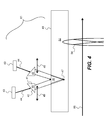
- FIGS 4 and 5 illustrate the optical imaging apparatus 80 according to the present invention, comprising laser sources 43 and prisms 45.
- Laser sources 43 emit two laser beams 44, from two adjacent locations to form a triangle shape when the two laser beams 44 meet on the plate surface 48 or inside the plate at the deepest cut point 47.
- a glass triangular wedge prism 45 is introduced in order to change the depth of laser beam 44 entrance into the plate 52 .
- the triangular wedge prism 45 moves in direction 49, when beams 44 hit the wide part 41 of the triangular wedge prism 45, laser beams 44 diffracts, thus enlarging the optical path, so the laser beams 44 will reach the plate surface 48.
- the triangular wedge prism 45 is placed in front of the laser source 43 at the triangle wedge wide part position 41, prior to entering into the flexographic plate 52.
- the wedge In order to perform the entrance and cut the flexographic plate 52 the wedge is moved relative to the laser source till it is placed in front of the narrow part 42 of the wedge. At the stage when the deep cut is performed, the wedge will not move to form a continuous large cut.
- the triangular wedge prism 45 will be moved till the triangle wedge wide part 41 of the wedge is placed in the front of the laser source 43. This operation will form a cut chunk 46 to be removed from the plate by the act of the rotation of the drum.
- the optical diffraction means such triangular wedge prism 45 can be introduced just in front of a single laser source 43, whereas the other laser source will be focused to the maximal depth in the plate material, this will result in a different shape of the cut chunk to be removed 46.
- the prisms moving laterally with respect to each other they may also be rotated or tilted to achieve a similar effect. Movement or rotation of prisms 45 may be accomplished by conventional means known in the art and represented schematically by movement mechanism 82.
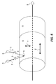
- Figure 6 shows the laser beam entrance position 61 into flexographic plate 52, till it hits the deepest cut point 47.
- the flexographic plate 52 mounted on the rotating drum 51 is moving in direction 64, thus causing the laser sources 43 to cut inside the flexographic plate 52 in the direction of the plate horizontal movement 63.
- the laser beam will exit the plate via exit position 62. This will form a cut chunk 65, illustrated in a 3D view.
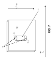
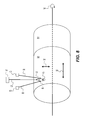
- Figures 7 and 8 show another embodiment for engraving into the flexographic plate 52.
- the pair of laser sources 43 are used without triangular wedge prism 45, the laser sources 43 are focused to the maximal depth of the plate material. This will result in cutting to the deepest cut point inside, to form main cut chunk area 71.
- a high power pulse laser source 74 is deployed to ablate the entrance and the exit of the chunk area 71.
- the entrance and exit areas 72 will be ablated by the pulse laser beams 73 from pulse laser source 74.
Landscapes
- Physics & Mathematics (AREA)
- Optics & Photonics (AREA)
- Engineering & Computer Science (AREA)
- Plasma & Fusion (AREA)
- Mechanical Engineering (AREA)
- Manufacturing & Machinery (AREA)
- Manufacture Or Reproduction Of Printing Formes (AREA)
- Laser Beam Processing (AREA)
Description
- This invention relates to an optical printing head and methods, for direct engraving of sensitive printing blocks. This is achieved by utilizing high power laser sources.
- Direct engraving of printing blocks such as flexographic plate or gravure cylinders requires carving three-dimensional (3D) images on plate material directly with a laser system. This is significantly different from two dimensional imaging techniques which require post processing steps to produce the three-dimensional features.
- This difference introduces several challenges for a laser imaging system for flexographic plates: the laser system must have sufficient power to ablate the material, and the laser spot should be small enough to achieve the fine detail required in quality printing. Although high power, high laser density does not necessary conflict with the laser focusability, from a practical perspective, these lasers have a high cost per watt ratio.
-
Figure 1 illustrates a flexographic printing plate. As illustrated inFigure 1 , because the flexographic plate is pressed directly on the printed media such as paper, packaging material, etc., theareas 10 which transfer ink to the printed media need to be elevated fromblank areas 11 which do not transfer ink. Typically theink transfer areas 10 require engraving at the depth of 70 µm, whereas nonink transfer areas 11 will need to be engraved to the depth of 500-700 µm. - The required depth of the blank areas is such that when the flexo plate is pressed against another surface, for instance the ink carrying agent, e.g., anilox roll, and subsequently on the printed media, these blank areas will be kept out of contact with other surfaces.
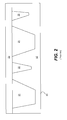
- In printing, a plate is pressed firmly against another surface, such as packaging. Because a flexo plate is deformable, imaging features separated by large blank areas will be deformed more strongly. As a result, large blank areas will be pushed towards the contact surface more strongly than small blank areas. This is depicted schematically in
Figure 2 , where the appliedpressure 20 pushes largeblank area 21 more strongly than smallblank area 22 towards press contact surface 23. Therefore, large blank areas must maintain greater depth than small areas, sufficient to prevent contact with the contact surface. To summarize the above, it follows that fine blank areas can be engraved by the laser system to a shallower relief than that required for large areas. - In graphic arts large, blank areas are identified to produce large non ink areas when printed. The regions with small blank areas correspond to fine detail areas when printed. The energy required to engrave a flexographic plate area, equivalent of 1 square centimeter in a depth of 1 µm is about 0.45 Joule. Typical electrical power required for removing flexographic plate non
ink transfer areas 11 will be on the order of 1000 of watts whereas,ink transfer areas 10 will need about 200 watts. The ratio of the above electrical consumption correlates to the depths ofink transfer areas 10 and nonink transfer areas 11, 70 µm forink transfer areas 10 and 500-700 µm forareas 11. - Document
US 2003/222969 A1 discloses an optical imaging apparatus for direct engraving of flexographic plates. Said optical imaging apparatus comprises at least two laser sources each capable of emitting laser beams and prisms placed in front of said laser sources, wherein said laser beams are capable of cutting out small parts of the surface of the flexographic plate. - The engraving process of flexographic plate production generates large amount of debris. This creates a challenge to remove the generated debris, consisting of small residual particles and emission of gas, in an effective manner. This adds extra complexity and cost to the process. The above problems are solved by the present invention.
- Briefly, according to one aspect of the present invention an optical imaging apparatus for direct engraving flexographic plates comprises at least two laser sources, each emitting laser beams. A triangular glass wedge prism is placed in front of each of the laser sources to alter an optical path of each of the laser beams. The laser beams cut the flexographic plate at different depths and cut out chunks of the flexographic plate.
- The engraving by slicing system ("EBS") according to the present invention takes advantage of the fact that while large solid areas need to be processed by the laser to a certain depth relief, fine detail areas can be processed to significantly shallower relief.
-
-
Figure 1 is a prior art schematic illustrating a relief in a flexographic plate showing elevated ink transfer areas and blank areas; -
Figure 2 is a prior art schematic illustrating a flexographic plate pressed against a surface. Columns separated by large blank areas are deformed more strongly, and, as a result, large blank areas are noticeably pushed towards the contact surface; -
Figure 3 is a schematic layout of engraving by slicing according to the present invention; -
Figure 4 is a schematic illustrating a an engraving by slicing optical system; -
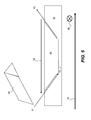
Figure 5 is a schematic layout of engraving by slicing concept with two laser systems; -
Figure 6 is a schematic illustrating a part from a flexographic plate cut out by the engraving by slicing system; -
Figure 7 is a schematic illustrating cutting a part from a flexographic plate by the engraving by slicing system, wherein the entrance and exit areas are ablated (not cut) by a laser pulse; and -
Figure 8 is a schematic layout of engraving by slicing, including a third laser for ablating entrance and exit areas. - The present invention describes an engraving by slicing printing head capable of engraving printing blocks, such as flexographic plates, gravure cylinders and letter press cylinders. Flexographic plates will be used in the examples and throughout the detailed description, although other types of plates may be cut according to the present invention. The present invention suggests several configurations, dependent upon the arrangement of an engraving device, described below.
- The present invention suggests using known laser engraving means to engrave in a 3D fashion all the
ink transfer areas 31 of the flexographic plate as is illustrated byFigure 3 . The removed nonink transfer chunks Laser beams directions ink transfer area 36 out of the flexographic plate, while the plate is rotating on the drum in thefast scan direction 54, with surface motion vertical to the laser beams. The laser beams are further applied at a determined delta step in theslow direction 55 to cut another chunk as is illustrated inFigure 3 , by applyinglaser beams ink transfer chunk 38, leaving a relative smallresidual chunk 37, due to the 2D engraving constraints of the suggested invention. The cut nonink transfer chunks - This invention introduces two major advantages to the flexographic plate production. The first is a substantial saving in the energy required to ablate the whole deep non ink transfer areas of a flexographic plate, such as removed non
ink transfer chunks - The second advantage lies in the fact that non ink transfer chunks such as 36 and 38 will be removed in relatively large pieces, as opposed to the large quantities of small particles and emitted gas, which is generated by the 3D laser ablation process. The proposed method will immensely simplify the debris removal process from the engraving device.
-
Figures 4 and5 illustrate theoptical imaging apparatus 80 according to the present invention, comprisinglaser sources 43 andprisms 45.Laser sources 43 emit twolaser beams 44, from two adjacent locations to form a triangle shape when the twolaser beams 44 meet on theplate surface 48 or inside the plate at the deepest cut point 47. In order to change the depth oflaser beam 44 entrance into the plate 52 a glasstriangular wedge prism 45 is introduced. Thetriangular wedge prism 45 moves indirection 49, whenbeams 44 hit thewide part 41 of thetriangular wedge prism 45,laser beams 44 diffracts, thus enlarging the optical path, so thelaser beams 44 will reach theplate surface 48. Whenlaser beams 44 hittriangular wedge prism 45 in the triangle wedgenarrow part 42 of thetriangular wedge prism 45, it will propagate and enter intoflexographic plate 52 into the deepest cut point 47.Laser beams 44 that will hittriangular wedge prism 45 in between triangle wedgewide part 41 and triangle wedgenarrow part 42 will enter intoflexographic plate 52 in betweenplate contact surface 48 and the deepest cut point 47. Beams intensity is adjusted during the process. The beams penetration into the material will be stopped, at the stage where the pair of beams will reach to the crossing point. - The
triangular wedge prism 45 is placed in front of thelaser source 43 at the triangle wedgewide part position 41, prior to entering into theflexographic plate 52. In order to perform the entrance and cut theflexographic plate 52 the wedge is moved relative to the laser source till it is placed in front of thenarrow part 42 of the wedge. At the stage when the deep cut is performed, the wedge will not move to form a continuous large cut. At the stage when the laser beams should exit the plate, thetriangular wedge prism 45 will be moved till the triangle wedgewide part 41 of the wedge is placed in the front of thelaser source 43. This operation will form acut chunk 46 to be removed from the plate by the act of the rotation of the drum. - The optical diffraction means such
triangular wedge prism 45 can be introduced just in front of asingle laser source 43, whereas the other laser source will be focused to the maximal depth in the plate material, this will result in a different shape of the cut chunk to be removed 46. Note also that while the examples show the prisms moving laterally with respect to each other, they may also be rotated or tilted to achieve a similar effect. Movement or rotation ofprisms 45 may be accomplished by conventional means known in the art and represented schematically bymovement mechanism 82. -
Figure 6 shows the laserbeam entrance position 61 intoflexographic plate 52, till it hits the deepest cut point 47. Theflexographic plate 52 mounted on therotating drum 51 is moving indirection 64, thus causing thelaser sources 43 to cut inside theflexographic plate 52 in the direction of the platehorizontal movement 63. At the point the cut is finalized the laser beam will exit the plate viaexit position 62. This will form acut chunk 65, illustrated in a 3D view. -
Figures 7 and8 show another embodiment for engraving into theflexographic plate 52. The pair oflaser sources 43 are used withouttriangular wedge prism 45, thelaser sources 43 are focused to the maximal depth of the plate material. This will result in cutting to the deepest cut point inside, to form maincut chunk area 71. In addition a high powerpulse laser source 74 is deployed to ablate the entrance and the exit of thechunk area 71. The entrance andexit areas 72 will be ablated by thepulse laser beams 73 frompulse laser source 74.
Claims (5)
- An optical imaging apparatus (80) for direct engraving of flexographic plate (52) mounted on a rotating drum (51), comprising:at least two laser sources (43) emitting two laser beams (44) in two directions to form a triangle shape, each emitting laser beams (44) being adapted to cut inside said flexographic plate;a triangular glass wedge prism (45) placed in front of each of said laser sources and movable relative to the laser source (43) to alter an optical path of each of said laser beams (44) for changing the depth of laser beam (44) entrance into the flexographic plate (52), in order to cut solid non ink transfer chunks (46) out of said flexographic plate and to remove said chunks from said flexographic plate by rotating the drum (51).
- The apparatus of claim 1 wherein said prism moves in unison, closer together or further apart, to cut out said chunks.
- The apparatus of claim 1 wherein said prism is placed in front of only one of said laser sources.
- The apparatus of claim 1 wherein said laser beams cut said flexographic plate in a fast scan direction (54).
- The apparatus of claim 1 wherein said prism tilts to cut out said chunks.
Applications Claiming Priority (2)
| Application Number | Priority Date | Filing Date | Title |
|---|---|---|---|
| US11/845,141 US8621996B2 (en) | 2007-08-27 | 2007-08-27 | Engraving of printing plates |
| PCT/US2008/009608 WO2009029167A1 (en) | 2007-08-27 | 2008-08-12 | Engraving of printing plates |
Publications (2)
| Publication Number | Publication Date |
|---|---|
| EP2180997A1 EP2180997A1 (en) | 2010-05-05 |
| EP2180997B1 true EP2180997B1 (en) | 2015-05-06 |
Family
ID=39865683
Family Applications (1)
| Application Number | Title | Priority Date | Filing Date |
|---|---|---|---|
| EP08795216.4A Not-in-force EP2180997B1 (en) | 2007-08-27 | 2008-08-12 | Engraving of printing plates |
Country Status (5)
| Country | Link |
|---|---|
| US (1) | US8621996B2 (en) |
| EP (1) | EP2180997B1 (en) |
| JP (1) | JP2010537848A (en) |
| CN (1) | CN101808823B (en) |
| WO (1) | WO2009029167A1 (en) |
Families Citing this family (17)
| Publication number | Priority date | Publication date | Assignee | Title |
|---|---|---|---|---|
| US8284229B2 (en) * | 2009-09-08 | 2012-10-09 | Eastman Kodak Company | Imaging head for 3D imaging |
| US20110236705A1 (en) | 2010-03-29 | 2011-09-29 | Ophira Melamed | Flexographic printing precursors and methods of making |
| US20110278767A1 (en) * | 2010-05-17 | 2011-11-17 | David Aviel | Direct engraving of flexographic printing plates |
| US9156299B2 (en) | 2011-06-30 | 2015-10-13 | Eastman Kodak Company | Laser-imageable flexographic printing precursors and methods of imaging |
| US20130101834A1 (en) | 2011-10-20 | 2013-04-25 | Dana Barshishat | Laser-imageable flexographic printing precursors and methods of imaging |
| US9156241B2 (en) | 2011-12-12 | 2015-10-13 | Eastman Kodak Company | Laser-imageable flexographic printing precursors and methods of relief imaging |
| US9266316B2 (en) | 2012-01-18 | 2016-02-23 | Eastman Kodak Company | Dual-layer laser-imageable flexographic printing precursors |
| DE102012202519A1 (en) * | 2012-02-17 | 2013-08-22 | Carl Zeiss Microscopy Gmbh | Methods and apparatus for preparing microscopic samples using pulsed light |
| US9571691B2 (en) * | 2012-04-27 | 2017-02-14 | Xerox Corporation | Imager array apparatus and systems |
| US9522523B2 (en) | 2012-04-30 | 2016-12-20 | Eastman Kodak Company | Laser-imageable flexographic printing precursors and methods of imaging |
| WO2015053757A1 (en) | 2013-10-09 | 2015-04-16 | Eastman Kodak Company | Direct laser-engraveable patternable elements and uses |
| JP5965454B2 (en) * | 2014-10-14 | 2016-08-03 | 株式会社アマダホールディングス | Direct diode laser processing apparatus and sheet metal processing method using the same |
| CN106552997B (en) * | 2015-09-23 | 2018-07-24 | 乐凯华光印刷科技有限公司 | The method that sheet metal sand screen mesh is handled based on mechanism of ultrashort-pulse laser ablation principle |
| DE102016100371A1 (en) * | 2016-01-11 | 2017-07-13 | Ball Europe Gmbh | Device for decorating containers |
| CA3024897A1 (en) * | 2016-05-20 | 2017-11-23 | Tresu A/S | Method for cutting out coating plates for use in digital printing units |
| CN106113900B (en) * | 2016-08-11 | 2019-06-14 | 浙江镭鹏智能科技有限公司 | Laser engraving machine |
| CN113478948B (en) * | 2021-07-01 | 2022-12-02 | 绍兴鑫昌印花机械科技有限公司 | Double-laser net making machine |
Family Cites Families (17)
| Publication number | Priority date | Publication date | Assignee | Title |
|---|---|---|---|---|
| BE760067A (en) | 1969-12-09 | 1971-06-09 | Applied Display Services | METHOD AND APPARATUS FOR THE MANUFACTURING OF SURFACE PLATES AS WELL AS PRINTING PLATES THEREFORE OBTAINED |
| DE19544502C1 (en) | 1995-11-29 | 1997-05-15 | Baasel Scheel Lasergraphics Gm | Laser engraving machine |
| JPH10315425A (en) * | 1997-05-20 | 1998-12-02 | Dainippon Screen Mfg Co Ltd | Laser platemaking apparatus |
| US20060249491A1 (en) | 1999-09-01 | 2006-11-09 | Hell Gravure Systems Gmbh | Laser radiation source |
| JP2002079645A (en) * | 2000-09-05 | 2002-03-19 | Asahi Kasei Corp | Manufacturing method of seamless cylinder printing plate |
| DE10109041A1 (en) * | 2001-02-24 | 2002-09-05 | Heidelberger Druckmasch Ag | Method and multi-beam scanning device for ablation of flexographic printing plates by laser engraving |
| EP1262315B8 (en) | 2001-05-25 | 2005-01-05 | Stork Prints Austria GmbH | Method and apparatus for making a printing plate |
| EP1262316B1 (en) | 2001-05-25 | 2004-11-17 | Stork Prints Austria GmbH | Method and apparatus for making a printing plate |
| DE10320272A1 (en) | 2002-05-28 | 2004-02-12 | Heidelberger Druckmaschinen Ag | Printing form production apparatus, has six-point mounting portions lying at corners of triangular laser module, in which V- shaped prisms with spheres, are mounted |
| JP2004299092A (en) * | 2003-03-28 | 2004-10-28 | Ricoh Microelectronics Co Ltd | Method for manufacturing printing plate |
| JP2006159800A (en) * | 2004-12-10 | 2006-06-22 | Dainippon Screen Mfg Co Ltd | Method and equipment for making printing plate |
| EP1642712B1 (en) * | 2004-09-30 | 2008-12-10 | Dainippon Screen Mfg. Co., Ltd. | Platemaking method and platemaking apparatus |
| JP2006224481A (en) * | 2005-02-18 | 2006-08-31 | Dainippon Screen Mfg Co Ltd | Platemaking equipment of printing plate |
| JP4703222B2 (en) | 2005-03-08 | 2011-06-15 | 大日本スクリーン製造株式会社 | Printing plate making equipment |
| US20070227386A1 (en) | 2006-04-03 | 2007-10-04 | Mcgaire Mark D | Plate processing system and method |
| US20080018943A1 (en) | 2006-06-19 | 2008-01-24 | Eastman Kodak Company | Direct engraving of flexographic printing plates |
| US7827912B2 (en) | 2006-12-22 | 2010-11-09 | Eastman Kodak Company | Hybrid optical head for direct engraving of flexographic printing plates |
-
2007
- 2007-08-27 US US11/845,141 patent/US8621996B2/en not_active Expired - Fee Related
-
2008
- 2008-08-12 WO PCT/US2008/009608 patent/WO2009029167A1/en not_active Ceased
- 2008-08-12 EP EP08795216.4A patent/EP2180997B1/en not_active Not-in-force
- 2008-08-12 JP JP2010522896A patent/JP2010537848A/en active Pending
- 2008-08-12 CN CN2008801048072A patent/CN101808823B/en not_active Expired - Fee Related
Also Published As
| Publication number | Publication date |
|---|---|
| US8621996B2 (en) | 2014-01-07 |
| CN101808823B (en) | 2012-06-27 |
| JP2010537848A (en) | 2010-12-09 |
| WO2009029167A1 (en) | 2009-03-05 |
| EP2180997A1 (en) | 2010-05-05 |
| CN101808823A (en) | 2010-08-18 |
| US20090057268A1 (en) | 2009-03-05 |
Similar Documents
| Publication | Publication Date | Title |
|---|---|---|
| US8621996B2 (en) | Engraving of printing plates | |
| EP2768626B1 (en) | Method and device for producing a structured surface on a steel embossing roller | |
| US9796202B2 (en) | Method and system for manufacturing intaglio printing plates for the production of security papers | |
| US6698354B2 (en) | Method and device for producing a printing block | |
| US8916798B2 (en) | Laser machining apparatus with switchable laser system and laser machining method | |
| JP2011521805A5 (en) | ||
| TW200800456A (en) | Laser processing method and laser processing apparatus | |
| CN103567643A (en) | Method of half-cut cutout processing of label paper | |
| JP2007530312A (en) | Method and apparatus for providing identification marks on securities | |
| US20060235564A1 (en) | Method and multifunctional system for producing laser-induced images on the surfaces of various materials and inside transparent materials | |
| US20110278767A1 (en) | Direct engraving of flexographic printing plates | |
| US8365662B2 (en) | Direct engraving of flexographic printing plates | |
| Bruening et al. | Large Scale Ultrafast Laser Micro Texturing with Multi-Beams. | |
| JP2013082589A (en) | Laser processing apparatus for glass substrate | |
| JP2006224481A (en) | Platemaking equipment of printing plate | |
| KR102012691B1 (en) | Method for manufacturing three dimensional shapes using laser and powder | |
| JP2003231398A (en) | Laser carving method and carving system | |
| US20140144894A1 (en) | Method and apparatus for engraving a flexible strip with pivoting a processing head about a longitudinal axis of a cylinder | |
| JP2016083835A (en) | Label producing device, and label producing method of the label producing device | |
| Hennig et al. | Large scale laser microstructuring of gravure print rollers | |
| JP3526199B2 (en) | Optical processing machine and method of manufacturing orifice plate using the same | |
| JP2006256186A (en) | Ink pattern formation unit in pad printing machine | |
| JPH07204872A (en) | Laser marking method |
Legal Events
| Date | Code | Title | Description |
|---|---|---|---|
| PUAI | Public reference made under article 153(3) epc to a published international application that has entered the european phase |
Free format text: ORIGINAL CODE: 0009012 |
|
| 17P | Request for examination filed |
Effective date: 20100205 |
|
| AK | Designated contracting states |
Kind code of ref document: A1 Designated state(s): AT BE BG CH CY CZ DE DK EE ES FI FR GB GR HR HU IE IS IT LI LT LU LV MC MT NL NO PL PT RO SE SI SK TR |
|
| AX | Request for extension of the european patent |
Extension state: AL BA MK RS |
|
| RIN1 | Information on inventor provided before grant (corrected) |
Inventor name: AVIEL, DAVID |
|
| DAX | Request for extension of the european patent (deleted) | ||
| REG | Reference to a national code |
Ref country code: DE Ref legal event code: R079 Ref document number: 602008038081 Country of ref document: DE Free format text: PREVIOUS MAIN CLASS: B41C0001050000 Ipc: B23K0026060000 |
|
| RIC1 | Information provided on ipc code assigned before grant |
Ipc: B23K 26/06 20140101AFI20140923BHEP Ipc: B41C 1/05 20060101ALI20140923BHEP Ipc: B23K 26/36 20140101ALI20140923BHEP |
|
| GRAP | Despatch of communication of intention to grant a patent |
Free format text: ORIGINAL CODE: EPIDOSNIGR1 |
|
| INTG | Intention to grant announced |
Effective date: 20141112 |
|
| GRAS | Grant fee paid |
Free format text: ORIGINAL CODE: EPIDOSNIGR3 |
|
| GRAA | (expected) grant |
Free format text: ORIGINAL CODE: 0009210 |
|
| AK | Designated contracting states |
Kind code of ref document: B1 Designated state(s): AT BE BG CH CY CZ DE DK EE ES FI FR GB GR HR HU IE IS IT LI LT LU LV MC MT NL NO PL PT RO SE SI SK TR |
|
| REG | Reference to a national code |
Ref country code: GB Ref legal event code: FG4D |
|
| REG | Reference to a national code |
Ref country code: CH Ref legal event code: EP |
|
| REG | Reference to a national code |
Ref country code: IE Ref legal event code: FG4D |
|
| REG | Reference to a national code |
Ref country code: AT Ref legal event code: REF Ref document number: 725339 Country of ref document: AT Kind code of ref document: T Effective date: 20150615 |
|
| REG | Reference to a national code |
Ref country code: DE Ref legal event code: R096 Ref document number: 602008038081 Country of ref document: DE Effective date: 20150618 |
|
| REG | Reference to a national code |
Ref country code: NL Ref legal event code: T3 |
|
| REG | Reference to a national code |
Ref country code: AT Ref legal event code: MK05 Ref document number: 725339 Country of ref document: AT Kind code of ref document: T Effective date: 20150506 |
|
| REG | Reference to a national code |
Ref country code: LT Ref legal event code: MG4D |
|
| PG25 | Lapsed in a contracting state [announced via postgrant information from national office to epo] |
Ref country code: PT Free format text: LAPSE BECAUSE OF FAILURE TO SUBMIT A TRANSLATION OF THE DESCRIPTION OR TO PAY THE FEE WITHIN THE PRESCRIBED TIME-LIMIT Effective date: 20150907 Ref country code: LT Free format text: LAPSE BECAUSE OF FAILURE TO SUBMIT A TRANSLATION OF THE DESCRIPTION OR TO PAY THE FEE WITHIN THE PRESCRIBED TIME-LIMIT Effective date: 20150506 Ref country code: HR Free format text: LAPSE BECAUSE OF FAILURE TO SUBMIT A TRANSLATION OF THE DESCRIPTION OR TO PAY THE FEE WITHIN THE PRESCRIBED TIME-LIMIT Effective date: 20150506 Ref country code: FI Free format text: LAPSE BECAUSE OF FAILURE TO SUBMIT A TRANSLATION OF THE DESCRIPTION OR TO PAY THE FEE WITHIN THE PRESCRIBED TIME-LIMIT Effective date: 20150506 Ref country code: NO Free format text: LAPSE BECAUSE OF FAILURE TO SUBMIT A TRANSLATION OF THE DESCRIPTION OR TO PAY THE FEE WITHIN THE PRESCRIBED TIME-LIMIT Effective date: 20150806 Ref country code: ES Free format text: LAPSE BECAUSE OF FAILURE TO SUBMIT A TRANSLATION OF THE DESCRIPTION OR TO PAY THE FEE WITHIN THE PRESCRIBED TIME-LIMIT Effective date: 20150506 |
|
| PG25 | Lapsed in a contracting state [announced via postgrant information from national office to epo] |
Ref country code: AT Free format text: LAPSE BECAUSE OF FAILURE TO SUBMIT A TRANSLATION OF THE DESCRIPTION OR TO PAY THE FEE WITHIN THE PRESCRIBED TIME-LIMIT Effective date: 20150506 Ref country code: IS Free format text: LAPSE BECAUSE OF FAILURE TO SUBMIT A TRANSLATION OF THE DESCRIPTION OR TO PAY THE FEE WITHIN THE PRESCRIBED TIME-LIMIT Effective date: 20150906 Ref country code: GR Free format text: LAPSE BECAUSE OF FAILURE TO SUBMIT A TRANSLATION OF THE DESCRIPTION OR TO PAY THE FEE WITHIN THE PRESCRIBED TIME-LIMIT Effective date: 20150807 Ref country code: LV Free format text: LAPSE BECAUSE OF FAILURE TO SUBMIT A TRANSLATION OF THE DESCRIPTION OR TO PAY THE FEE WITHIN THE PRESCRIBED TIME-LIMIT Effective date: 20150506 Ref country code: BG Free format text: LAPSE BECAUSE OF FAILURE TO SUBMIT A TRANSLATION OF THE DESCRIPTION OR TO PAY THE FEE WITHIN THE PRESCRIBED TIME-LIMIT Effective date: 20150806 |
|
| PG25 | Lapsed in a contracting state [announced via postgrant information from national office to epo] |
Ref country code: EE Free format text: LAPSE BECAUSE OF FAILURE TO SUBMIT A TRANSLATION OF THE DESCRIPTION OR TO PAY THE FEE WITHIN THE PRESCRIBED TIME-LIMIT Effective date: 20150506 Ref country code: DK Free format text: LAPSE BECAUSE OF FAILURE TO SUBMIT A TRANSLATION OF THE DESCRIPTION OR TO PAY THE FEE WITHIN THE PRESCRIBED TIME-LIMIT Effective date: 20150506 |
|
| REG | Reference to a national code |
Ref country code: DE Ref legal event code: R097 Ref document number: 602008038081 Country of ref document: DE |
|
| PG25 | Lapsed in a contracting state [announced via postgrant information from national office to epo] |
Ref country code: CZ Free format text: LAPSE BECAUSE OF FAILURE TO SUBMIT A TRANSLATION OF THE DESCRIPTION OR TO PAY THE FEE WITHIN THE PRESCRIBED TIME-LIMIT Effective date: 20150506 Ref country code: SK Free format text: LAPSE BECAUSE OF FAILURE TO SUBMIT A TRANSLATION OF THE DESCRIPTION OR TO PAY THE FEE WITHIN THE PRESCRIBED TIME-LIMIT Effective date: 20150506 Ref country code: RO Free format text: LAPSE BECAUSE OF NON-PAYMENT OF DUE FEES Effective date: 20150506 Ref country code: PL Free format text: LAPSE BECAUSE OF FAILURE TO SUBMIT A TRANSLATION OF THE DESCRIPTION OR TO PAY THE FEE WITHIN THE PRESCRIBED TIME-LIMIT Effective date: 20150506 |
|
| PLBE | No opposition filed within time limit |
Free format text: ORIGINAL CODE: 0009261 |
|
| STAA | Information on the status of an ep patent application or granted ep patent |
Free format text: STATUS: NO OPPOSITION FILED WITHIN TIME LIMIT |
|
| PG25 | Lapsed in a contracting state [announced via postgrant information from national office to epo] |
Ref country code: LU Free format text: LAPSE BECAUSE OF FAILURE TO SUBMIT A TRANSLATION OF THE DESCRIPTION OR TO PAY THE FEE WITHIN THE PRESCRIBED TIME-LIMIT Effective date: 20150812 Ref country code: MC Free format text: LAPSE BECAUSE OF FAILURE TO SUBMIT A TRANSLATION OF THE DESCRIPTION OR TO PAY THE FEE WITHIN THE PRESCRIBED TIME-LIMIT Effective date: 20150506 |
|
| REG | Reference to a national code |
Ref country code: CH Ref legal event code: PL |
|
| 26N | No opposition filed |
Effective date: 20160209 |
|
| PG25 | Lapsed in a contracting state [announced via postgrant information from national office to epo] |
Ref country code: LI Free format text: LAPSE BECAUSE OF NON-PAYMENT OF DUE FEES Effective date: 20150831 Ref country code: IT Free format text: LAPSE BECAUSE OF FAILURE TO SUBMIT A TRANSLATION OF THE DESCRIPTION OR TO PAY THE FEE WITHIN THE PRESCRIBED TIME-LIMIT Effective date: 20150506 Ref country code: CH Free format text: LAPSE BECAUSE OF NON-PAYMENT OF DUE FEES Effective date: 20150831 |
|
| PG25 | Lapsed in a contracting state [announced via postgrant information from national office to epo] |
Ref country code: SI Free format text: LAPSE BECAUSE OF FAILURE TO SUBMIT A TRANSLATION OF THE DESCRIPTION OR TO PAY THE FEE WITHIN THE PRESCRIBED TIME-LIMIT Effective date: 20150506 |
|
| REG | Reference to a national code |
Ref country code: IE Ref legal event code: MM4A |
|
| REG | Reference to a national code |
Ref country code: FR Ref legal event code: ST Effective date: 20160429 |
|
| PG25 | Lapsed in a contracting state [announced via postgrant information from national office to epo] |
Ref country code: IE Free format text: LAPSE BECAUSE OF NON-PAYMENT OF DUE FEES Effective date: 20150812 |
|
| PG25 | Lapsed in a contracting state [announced via postgrant information from national office to epo] |
Ref country code: BE Free format text: LAPSE BECAUSE OF FAILURE TO SUBMIT A TRANSLATION OF THE DESCRIPTION OR TO PAY THE FEE WITHIN THE PRESCRIBED TIME-LIMIT Effective date: 20150506 Ref country code: FR Free format text: LAPSE BECAUSE OF NON-PAYMENT OF DUE FEES Effective date: 20150831 |
|
| PG25 | Lapsed in a contracting state [announced via postgrant information from national office to epo] |
Ref country code: MT Free format text: LAPSE BECAUSE OF FAILURE TO SUBMIT A TRANSLATION OF THE DESCRIPTION OR TO PAY THE FEE WITHIN THE PRESCRIBED TIME-LIMIT Effective date: 20150506 |
|
| PG25 | Lapsed in a contracting state [announced via postgrant information from national office to epo] |
Ref country code: HU Free format text: LAPSE BECAUSE OF FAILURE TO SUBMIT A TRANSLATION OF THE DESCRIPTION OR TO PAY THE FEE WITHIN THE PRESCRIBED TIME-LIMIT; INVALID AB INITIO Effective date: 20080812 |
|
| PG25 | Lapsed in a contracting state [announced via postgrant information from national office to epo] |
Ref country code: SE Free format text: LAPSE BECAUSE OF FAILURE TO SUBMIT A TRANSLATION OF THE DESCRIPTION OR TO PAY THE FEE WITHIN THE PRESCRIBED TIME-LIMIT Effective date: 20150506 Ref country code: CY Free format text: LAPSE BECAUSE OF FAILURE TO SUBMIT A TRANSLATION OF THE DESCRIPTION OR TO PAY THE FEE WITHIN THE PRESCRIBED TIME-LIMIT Effective date: 20150506 |
|
| PG25 | Lapsed in a contracting state [announced via postgrant information from national office to epo] |
Ref country code: TR Free format text: LAPSE BECAUSE OF FAILURE TO SUBMIT A TRANSLATION OF THE DESCRIPTION OR TO PAY THE FEE WITHIN THE PRESCRIBED TIME-LIMIT Effective date: 20150506 |
|
| REG | Reference to a national code |
Ref country code: DE Ref legal event code: R082 Ref document number: 602008038081 Country of ref document: DE Representative=s name: PATENTANWALTSKANZLEI LIERMANN-CASTELL, DE Ref country code: DE Ref legal event code: R081 Ref document number: 602008038081 Country of ref document: DE Owner name: MIRACLON CORP., WILMINGTON, US Free format text: FORMER OWNER: EASTMAN KODAK CO., ROCHESTER, N.Y., US Ref country code: DE Ref legal event code: R081 Ref document number: 602008038081 Country of ref document: DE Owner name: MIRACLON CORP., OAKDALE, US Free format text: FORMER OWNER: EASTMAN KODAK CO., ROCHESTER, N.Y., US |
|
| REG | Reference to a national code |
Ref country code: GB Ref legal event code: 732E Free format text: REGISTERED BETWEEN 20190516 AND 20190522 |
|
| REG | Reference to a national code |
Ref country code: NL Ref legal event code: PD Owner name: MIRACLON CORPORATION; US Free format text: DETAILS ASSIGNMENT: CHANGE OF OWNER(S), ASSIGNMENT; FORMER OWNER NAME: EASTMAN KODAK COMPANY Effective date: 20190430 |
|
| PGFP | Annual fee paid to national office [announced via postgrant information from national office to epo] |
Ref country code: NL Payment date: 20200811 Year of fee payment: 13 |
|
| PGFP | Annual fee paid to national office [announced via postgrant information from national office to epo] |
Ref country code: GB Payment date: 20200819 Year of fee payment: 13 Ref country code: DE Payment date: 20200828 Year of fee payment: 13 |
|
| REG | Reference to a national code |
Ref country code: DE Ref legal event code: R082 Ref document number: 602008038081 Country of ref document: DE Representative=s name: PATENTANWALTSKANZLEI LIERMANN-CASTELL, DE Ref country code: DE Ref legal event code: R081 Ref document number: 602008038081 Country of ref document: DE Owner name: MIRACLON CORP., OAKDALE, US Free format text: FORMER OWNER: MIRACLON CORP., WILMINGTON, DELAWARE, US |
|
| REG | Reference to a national code |
Ref country code: DE Ref legal event code: R119 Ref document number: 602008038081 Country of ref document: DE |
|
| REG | Reference to a national code |
Ref country code: NL Ref legal event code: MM Effective date: 20210901 |
|
| GBPC | Gb: european patent ceased through non-payment of renewal fee |
Effective date: 20210812 |
|
| PG25 | Lapsed in a contracting state [announced via postgrant information from national office to epo] |
Ref country code: NL Free format text: LAPSE BECAUSE OF NON-PAYMENT OF DUE FEES Effective date: 20210901 |
|
| PG25 | Lapsed in a contracting state [announced via postgrant information from national office to epo] |
Ref country code: GB Free format text: LAPSE BECAUSE OF NON-PAYMENT OF DUE FEES Effective date: 20210812 Ref country code: DE Free format text: LAPSE BECAUSE OF NON-PAYMENT OF DUE FEES Effective date: 20220301 |