EP2180985B1 - Rasierer mit vorspannungselement für die klingeneinheit - Google Patents
Rasierer mit vorspannungselement für die klingeneinheit Download PDFInfo
- Publication number
- EP2180985B1 EP2180985B1 EP08807398A EP08807398A EP2180985B1 EP 2180985 B1 EP2180985 B1 EP 2180985B1 EP 08807398 A EP08807398 A EP 08807398A EP 08807398 A EP08807398 A EP 08807398A EP 2180985 B1 EP2180985 B1 EP 2180985B1
- Authority
- EP
- European Patent Office
- Prior art keywords
- razor
- blade unit
- pivotal frame
- cartridge
- handle
- Prior art date
- Legal status (The legal status is an assumption and is not a legal conclusion. Google has not performed a legal analysis and makes no representation as to the accuracy of the status listed.)
- Active
Links
- 238000004519 manufacturing process Methods 0.000 description 2
- 230000000694 effects Effects 0.000 description 1
- 238000003780 insertion Methods 0.000 description 1
- 230000037431 insertion Effects 0.000 description 1
- 238000000034 method Methods 0.000 description 1
- 238000012986 modification Methods 0.000 description 1
- 230000004048 modification Effects 0.000 description 1
- 230000000717 retained effect Effects 0.000 description 1
Images


Classifications
-
- B—PERFORMING OPERATIONS; TRANSPORTING
- B26—HAND CUTTING TOOLS; CUTTING; SEVERING
- B26B—HAND-HELD CUTTING TOOLS NOT OTHERWISE PROVIDED FOR
- B26B21/00—Razors of the open or knife type; Safety razors or other shaving implements of the planing type; Hair-trimming devices involving a razor-blade; Equipment therefor
- B26B21/08—Razors of the open or knife type; Safety razors or other shaving implements of the planing type; Hair-trimming devices involving a razor-blade; Equipment therefor involving changeable blades
- B26B21/14—Safety razors with one or more blades arranged transversely to the handle
- B26B21/22—Safety razors with one or more blades arranged transversely to the handle involving several blades to be used simultaneously
- B26B21/222—Safety razors with one or more blades arranged transversely to the handle involving several blades to be used simultaneously with the blades moulded into, or attached to, a changeable unit
- B26B21/225—Safety razors with one or more blades arranged transversely to the handle involving several blades to be used simultaneously with the blades moulded into, or attached to, a changeable unit the changeable unit being resiliently mounted on the handle
Definitions
- the present invention relates to shaving razors and more particularly to shaving razors including a pivotal frame and a blade unit and a biasing member that biases the blade unit.
- a shaving razor in its basic form includes a handle and a cartridge in which one or more blades are mounted.
- a disposable razor when the blades become dull from use, the entire razor is discarded and replaced with a new razor.
- the cartridge In a shaving system when the blades become dull from use, the cartridge is discarded and replaced on the handle with a new cartridge.
- the blades are resiliently mounted in the shaving cartridge and deflect under the force of skin contact during shaving.
- the connection of the cartridge to the handle provides a pivotal mounting on the cartridge with respect to the handle so that the cartridge angle adjusts to follow the contours of the skin surface being shaved.
- the cartridge can be biased toward an at rest position by the action of a spring-biased plunger and a cam follower carried on the handle against a cam surface found on the cartridge.
- cartridges comprised of two components such as a pivotal frame and a blade unit there is a need to provide a biasing member that acts on the blade unit to bias the blade unit into the preferred shaving position.
- WO2005/0172494 discloses a razor comprising a shaving cartridge comprising a pivotal frame, a blade unit moveably secured to said pivotal frame and an interconnect member; said blade unit carrying one or more blades and having camming surface, said interconnect member having a pivotal support structure that pivotally supports said pivotal frame for pivoting about a pivot axis.
- a razor as defined above is characterized in that it further comprises a biasing member that has a cam follower surface and extends from said interconnect member to act on said camming surface to bias said blade unit and a handle secured to said interconnect member.
- a razor in accordance with the present invention, includes a shaving cartridge comprising a pivotal frame, a blade unit moveably secured to the pivotal frame and an interconnect member.
- the biasing member comprises a spring biased plunger or a cantilever spring.
- the razor may include one, two or more biasing members.
- the handle comprises a cartridge support structure shaped to mate with a recess in the interconnect member and the biasing member extends from the cartridge support structure.
- the pivotal frame has an upper surface and a lower surface and the cam follower biases the blade unit toward the upper surface of the pivotal frame.
- the camming surface permits the pivotal frame to pivot in only one direction from an at rest position.
- the razor may be disposable where the entire razor is discarded when the blades become dull from use or a system where the cartridge is discarded and replaced when the blades become dull from use and is replaced on the handle with a new cartridge.
- the interconnect member comprises a base structure.
- the cartridge support structure of the handle is shaped to mate with a recess in the base structure of the interconnect member.
- the blade unit is moveably secured to the pivotal frame between a first position and a second position and the biasing member that has a cam follower surface and extends from the interconnect member and through the cam follower opening to act on the camming surface to bias the blade unit toward the second position.
- shaving razor 10 includes handle 12 and replaceable shaving cartridge 14. As shown in FIG 2 , cartridge 14 is releasably secured to handle 12 such that it is removable from handle 12. Cartridge 14 includes pivotal frame 16 and blade unit 18 moveably secured to pivotal frame 16. Cartridge 14 also includes interconnect member 24 on which pivotal frame 16 is pivotally mounted. Interconnect member 24 includes central base 27, which removably and fixedly attaches to extension 26 of handle 12 and two arms 28 extending from central base 27 that pivotally support pivotal frame 16 at its two sides.
- Pivotal frame 16 includes an upper surface 30 and a lower surface 31.
- Upper surface 30 of pivotal frame 16 is the skin contacting surface or shaving surface of pivotal frame 16.
- Upper surface 30 of pivotal frame 16 includes a guard 20 and a cap 22.
- Blade unit 18 includes one more blades 19. In the embodiment shown in FIGS. 1 and 2 , blade unit 18 includes three blades 19. Blade unit 18 also includes camming surface 32.
- Cartridge support structure 42 of handle 12 extends from the end of elongated gripping portion 41.
- Cartridge support structure 42 includes shaped extension 26 and the components that provide a biasing member 43 which in this embodiment is a spring-biased plunger 44 for biasing the blade unit 18 relative to pivotal frame 16 and pivotal frame 16 relative to interconnect member 24. It also includes components that provide for ejection of cartridge 14 from handle 12.
- FIG. 3 there is shown an exploded view of the components of handle 12.
- Spring-biased plunger 44, spring 46 and U-shaped ejector 48 are received within recess 49 of cartridge support structure 42.
- Ejector button 50 is received in opening 52 on the top surface of support structure 42 and has bottom extensions 54 that are received within rectangular region 56 at the back narrow portion of ejector 48.
- FIGS. 4-11 show the details of spring-biased plunger 44, ejector 48, button 50 and cartridge support structure 42.
- Recess 49 within cartridge support structure 42 has wide front portion 76 for receiving arms 78 of ejector 48 and a narrower portion 80 for receiving narrower portion 82 of ejector 48.
- Rectangular region 56 at narrow portion 83 of ejector 48 is generally aligned with opening 52 at the upper surface of support structure 42, though rectangular region 56 is movable with respect to opening 52 along slide axis 83 as ejector 48 is pushed outward by ejector button 50.
- Each extension 54 of ejector button 50 has an outwardly directed groove 84 that slides on a respective track 86 within opening 52 along axis 83.
- the upper surfaces 85 defining grooves 84 slide on the upper surface 89 of tracks 86, and the lower surfaces 91 defining grooves 84 effect capture on or about the lower surfaces 93 of track 86.
- Extensions 54 have inclined surfaces 87 that coact with the curved upper corners of tracks 86 to deflect extensions 54 inward as button 50 is inserted into cartridge support structure 42. When grooves 84 on extension 54 align with tracks 86, extensions 54 substantially return to their undeflected position and lock ejector button 50 in place within opening 52.
- Ejector 48 is placed within recess 49 before button 50 is inserted so that the ends of extensions 54 will be located within rectangular region 56 so as to retain ejector 48 within cartridge support structure 42. Extensions 54 push against surfaces 94 of ejector 48 when ejector button 50 is pushed toward the end of handle 12. After button 50 has been inserted, upper vertical surfaces 96 of extensions 54 sit within the space between upper surfaces 98 of opening 52.
- Spring 46 extends through the space between extensions 54 and is guided by the curved lower surface of spring guide 90 on button 50. As shown in FIG. 7 , the lower surface defining recess 49 also has a curved central portion 92 to receive and guide spring 46.
- plunger 44 has flat body 106, cylindrical rear extension 100 for receiving spring 46 ( FIG. 3 ), curved front cam follower portion 102 for action on the camming surface 32 of pivotal frame 16 ( FIG. 2 ), side arms 104 and aligned rear guide portions 108.
- Flat body 106 is positioned within the flat front portion of recess 49.
- the portions of side arms 104 and aligned rear guide portions 108 above and below body 106 are located within slots 110, 112 located on both sides of asymmetrical extension 26.
- Side arms 104 have stop surfaces 114 that prevent forward movement of plunger 44 beyond the front of slot 110 and 112.
- the portions of side arms 104 and guide portions 108 above and below recess 49 within slots 110, 112 act as guides to guide the sliding action of plunger 44 along axis 83.
- Side arms 104 have inclined surfaces 120 to cause downward biasing of arms 104 when plunger 44 is inserted into recess 49 until stop surfaces 114 advance past the front ends of slots 110, 112 and stop surfaces 114 snap into position within the respective slot. Because slots 110, 112 are provided on both sides of extensions 26, plunger 44 can be inserted in either position orientation, with the stop surface 114 directed into slot 110 or 112.
- one surface of extension 26 includes depressions 122 for receiving detents within central base structure 27 of cartridge 14 in order to retain cartridge 14 on extension 26.
- elongated hand gripping portion 41 may be a single component or multiple components secured together to form a unitary structure.
- ejector 48 is first inserted into recess 49.
- Spring 46 and plunger 44 are then inserted.
- Inclined surfaces 120 of side arms 104 are biased during insertion toward the nuddle of the recess and then snap into slot 110 or 112 (depending upon plunger orientation) locking plunger 44, spring 46, and ejector 48 in place in cartridge support structure 42.
- Spring 46 acts both to bias ejector 48 backward against the surfaces of recess 49 and button extensions 54 and to bias plunger 44 forward, stop surfaces 114 being biased against the forward edges of slot 110 or 112.
- Button 50 is inserted into opening 52 after ejector 48 has been inserted into position.
- Inclined surfaces 87 are biased inward by the curved upper portions of rails 86, and ejector button 50 is snapped into place within tracks 86 being located within grooves 84.
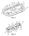
- Pivotal frame 16 includes two pair of interior walls 33 and 34 defining opening 35. Interior walls 33 are longer than interior walls 34. Interior walls 33 include a plurality of prongs 36 along each interior face 38. The prongs 36 are only shown on one interior face in FIG. 12 , Each wall 33 also includes a plurality of guide grooves 39 along the top of the wall.
- Blade unit 18 containing blades 19.
- Blade unit 18 includes a pair of long walls 58 and a pair of short walls 59.
- a pair of clips 60 secure blades 19 within blade unit 18.
- Long walls 58 each contain a plurality of indetents 61. The indents 61 are only shown on one wall 58 in FIG. 13 .
- Blade unit 18 also includes three guide bars 63. Central guide bar 63 includes camming surface 32.
- Blade unit 18 When joining blade unit 18 with pivotal frame 16 a snap fit connection is formed between blade unit 18 and pivotal frame 16.
- Blade unit 18 is sized and shaped to fit within opening 35 of pivotal frame 16.
- Guide bars 63 on blade unit 18 rest within grooves 39 of pivotal frame 16.
- Indents 61 on blade unit 18 engage with prongs 36 of blade unit 18.
- the engagement of indents 61 with prongs 36 moveably secures pivotal frame 16 to blade unit 18.
- the term moveably secures is used to describe the condition where the blade unit 18 is secured to the pivotal frame 16 but is capable of relatively small movements within the pivotal frame.
- the allowance for small movements comes about as there is some tolerance built in to the prong and indent dimensions respectively such that they are not an exact match. That is, the prong dimensions are slightly smaller than the indent dimensions. Such tolerances are necessary for manufacturing purposes.
- Cam follower 102 of biasing member 43 pushes against camming surface 32 to bias blade unit 18 into the preferred shaving position, i.e., toward upper surface 30 of pivotal frame 16.
- the blade unit 18 moves within pivotal frame 16 between a first position and a second position. In the first position the blade unit 18 is nearest the lower surface 31 of pivotal frame 16. In the second position the blade unit 18 is nearest the upper surface 30 of pivotal frame 16.
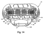
- FIG. 14 shows further details of replaceable cartridge 14 and its pivotal movement.
- Interconnect member 24 is shown assembled to pivotal frame 16 with pivotal support ends 72 retained within recess 68.
- Base structure 27 has a shaped recess 130 that has the same shape as extension 26 ( FIG. 2 ) and mates with extension 26.
- Arms 28 of interconnect member 24 deflect as support ends 72 are inserted through the openings to recesses 131 and then snap back to an undeflected potion after ends 72 are within recesses 131 to retain ends 72 in place.
- projections 132 within recess 130 of base 27 mate with depressions 122 of extension 26.
- opening 74 which permits spring-biased plunger 44 to extend through and from base 27 and to interact with camming surface 32 on blade unit 18.
- FIG. 16 shows the range of pivotal motion for cartridge 14.
- Cartridge 14 is shown with interconnect member 24 and arms 28 of interconnect member 24.
- cartridge 14 will pivot clockwise and generally follow the contours of the user's face, being biased by plunger 44.
- the cap up initial orientation will cause the blade closer to cap 22 to initially be pushed against the skin more than the blades closer to guard.
- the pivot at the region of guard 20 and the light return force cause the cartridge to be "guard heavy" during shaving with a higher load on the guard than the cap.
- the base structure could be held on to the pivotal frame with a releasable latch.
- the blades could be loaded from the bottom instead of the top.
- the cartridge support structure could be made as a unit separate from the handle and attached to it.
- the pivotal connection could be provided by pins in respective holes, shell bearding and other techniques.
- a shaving system is depicted in which when the blades become dull from use, the cartridge is discarded and replaced on the handle with a new cartridge.
- the present invention may also be practiced with a disposable razor such that when the blades become dull from use, the entire razor is discarded and replaced with a new razor.
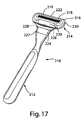
- disposable shaving razor 210 includes handle 212 and shaving cartridge 214.
- Cartridge 214 is secured to handle 212 such that it is not removable from handle 212.
- Cartridge 214 includes pivotal frame 216 and blade unit 218 moveably secured to pivotal frame 216.
- Cartridge 214 also includes interconnect member 224 on which pivotal frame 216 is pivotally mounted.
- Interconnect member 224 includes central base 227, which is fixedly attached to handle 212 and two arms 228 extending from central base 227 that pivotally support pivotal frame 216 at its two sides.
- Pivotal frame 216 includes an upper surface 230 and a lower surface 231.
- Upper surface 230 of pivotal frame 216 is the skin contacting surface or shaving surface of pivotal frame 216.
- Upper surface 230 of pivotal frame 216 includes a guard 220 and a cap 222.
- Blade unit 218 includes one more blades 219. In the embodiment shown in FIGS. 17 and 18 , blade unit 218 includes three blades 219. Blade unit 218 also includes camming surface 232.
- Cartridge support structure 242 of handle 212 extends from the end of elongated gripping portion 241.
- Interconnect member 224 is secured to cartridge support structure 242 of handle 212.
- Biasing member 243 which in this embodiment is a cantilever spring 244 extends from interconnect member 224 to act on the camming surface 232 to bias the blade unit 218.
- the cantilever spring 244 extends from the central base 227 of the interconnect member 224.
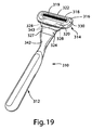
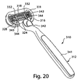
- disposable shaving razor 310 includes handle 312 and shaving cartridge 314.
- Cartridge 314 is secured to handle 312 such that it is not removable from handle 312.
- Cartridge 314 includes pivotal frame 316 and blade unit 318 moveably secured to pivotal frame 316.
- Cartridge 314 also includes interconnect member 324 on which pivotal frame 316 is pivotally mounted.
- Interconnect member 324 includes central base 327, which is fixedly attached to handle 312 and two arms 328 extending from central base 327 that pivotally support pivotal frame 316 at its two sides.
- Pivotal frame 316 includes an upper surface 330 and a lower surface 331.
- Upper surface 330 of pivotal frame 316 is the skin contacting surface or shaving surface of pivotal frame 316.
- Upper surface 330 of pivotal frame 316 includes a guard 330 and a cap 332.
- Blade unit 318 includes one more blades 319. Blade unit 318 also includes camming surfaces 332.
- Cartridge support structure 342 of handle 312 extends from the end of elongated gripping portion 341.
- Interconnect member 324 is secured to cartridge support structure 342 of handle 312.
- Biasing member 343 which in this embodiment include two cantilever springs 344 extend from interconnect member 324 to act on the camming surfaces 332 to bias the blade unit 318.
- the cantilever springs 344 extend from the central base 327 of the interconnect member 324.
Claims (10)
- Rasierer (10), umfassend:eine Rasierkartusche (14), umfassend einen Schwenkrahmen (16), eine Klingeneinheit (18), die beweglich an dem Schwenkrahmen (16) befestigt ist, und ein Verbindungselement (24), einen Griff (12), der an dem Verbindungselement (24) befestigt ist,wobei die Klingeneinheit (18) eine oder mehrere Klingen (19) trägt,wobei das Verbindungselement (24) eine schwenkbare Tragestruktur aufweist, die den Schwenkrahmen (16) für eine Schenkbewegung um eine Schwenkachse drehbar trägt, wobei der Rasierer dadurch gekennzeichnet ist, dass die Klingeneinheit (18) eine Nockenoberfläche aufweist, und dadurch, dass er ferner Folgendes umfasst:ein Vorspannelement (44), das eine Nockenstößeloberfläche aufweist und sich von dem Verbindungselement aus erstreckt, um auf die Nockenoberfläche einzuwirken und die Klingeneinheit vorzuspannen.
- Rasierer nach Anspruch 1, wobei das Vorspannelement einen gefederten Druckstempel (44) umfasst.
- Rasierer nach Anspruch 1, wobei das Vorspannelement eine Auslegerfeder umfasst.
- Rasierer nach Anspruch 1, wobei der Rasierer mindestens zwei Vorspannelemente umfasst.
- Rasierer nach einem der vorstehenden Ansprüche, wobei der Griff eine Kartuschentragestruktur umfasst, die so geformt ist, dass sie mit einer Aussparung in dem Verbindungselement zusammenpasst, wobei sich das Vorspannelement von der Kartuschentragestruktur aus erstreckt.
- Rasierer nach einem der vorstehenden Ansprüche, wobei der Schwenkrahmen eine obere Oberfläche und eine untere Oberfläche besitzt, wobei der Nockenstößel die Klingeneinheit zu der oberen Oberfläche des Schwenkrahmens hin vorspannt.
- Rasierer nach einem der vorstehenden Ansprüche, wobei die Nockenoberfläche ermöglicht, dass der Schwenkrahmen aus einer Ruheposition nur in eine Richtung schwenkt.
- Rasierer nach einem der vorstehenden Ansprüche, wobei das Verbindungselement eine zentrale Basisstruktur aufweist und sich das Vorspannelement von der zentralen Basisstruktur des Verbindungselements aus erstreckt.
- Rasierer nach Anspruch 1, wobei die Klingeneinheit beweglich zwischen einer ersten Position und einer zweiten Position an dem Schwenkrahmen befestigt ist.
- Rasierer nach Anspruch 9, wobei die Nockenstößeloberfläche auf die Nockenoberfläche einwirkt, um die Klingeneinheit zu der zweiten Position hin vorzuspannen.
Priority Applications (1)
| Application Number | Priority Date | Filing Date | Title |
|---|---|---|---|
| PL08807398T PL2180985T3 (pl) | 2007-08-30 | 2008-08-21 | Maszynka do golenia z elementem odchylającym zespoł ostrza |
Applications Claiming Priority (2)
| Application Number | Priority Date | Filing Date | Title |
|---|---|---|---|
| US11/897,313 US7770294B2 (en) | 2007-08-30 | 2007-08-30 | Razor with blade unit biasing member |
| PCT/IB2008/053362 WO2009027910A2 (en) | 2007-08-30 | 2008-08-21 | Razor with blade unit biasing member |
Publications (2)
| Publication Number | Publication Date |
|---|---|
| EP2180985A2 EP2180985A2 (de) | 2010-05-05 |
| EP2180985B1 true EP2180985B1 (de) | 2012-10-10 |
Family
ID=40329322
Family Applications (1)
| Application Number | Title | Priority Date | Filing Date |
|---|---|---|---|
| EP08807398A Active EP2180985B1 (de) | 2007-08-30 | 2008-08-21 | Rasierer mit vorspannungselement für die klingeneinheit |
Country Status (14)
| Country | Link |
|---|---|
| US (2) | US7770294B2 (de) |
| EP (1) | EP2180985B1 (de) |
| JP (1) | JP5518710B2 (de) |
| KR (1) | KR20100041856A (de) |
| CN (1) | CN101790444B (de) |
| AU (1) | AU2008291733B2 (de) |
| BR (1) | BRPI0815809B1 (de) |
| CA (1) | CA2697973C (de) |
| CL (1) | CL2008002569A1 (de) |
| MX (1) | MX2010002189A (de) |
| PL (1) | PL2180985T3 (de) |
| RU (1) | RU2442684C2 (de) |
| TW (1) | TW200927406A (de) |
| WO (1) | WO2009027910A2 (de) |
Families Citing this family (55)
| Publication number | Priority date | Publication date | Assignee | Title |
|---|---|---|---|---|
| US7770294B2 (en) * | 2007-08-30 | 2010-08-10 | The Gillette Company | Razor with blade unit biasing member |
| GB0716941D0 (en) * | 2007-08-31 | 2007-10-10 | Knowledge & Merchandising Inc | Razor handle |
| CN101965252A (zh) * | 2008-02-27 | 2011-02-02 | 美国安全剃刀公司 | 剃须系统 |
| US8671577B2 (en) * | 2008-12-03 | 2014-03-18 | Thomas A. Brown | Razor with independent suspension |
| PL2266727T3 (pl) * | 2009-06-22 | 2016-04-29 | Gillette Co | Sposób wytwarzania funkcjonalnych wkładów maszynek do golenia |
| JP5934097B2 (ja) | 2009-09-30 | 2016-06-15 | キム コール | 布地手入れ用具 |
| US20110088269A1 (en) * | 2009-10-21 | 2011-04-21 | Walker Jr Vincent Paul | Docking Mechanisms for Shaving Razors and Cartridges |
| US20110247217A1 (en) * | 2010-04-12 | 2011-10-13 | Robert Harold Johnson | Shaving cartridge having a front pivoting hood with a biasing member |
| US9073226B2 (en) * | 2011-02-09 | 2015-07-07 | The Gillette Company | Pivoting razor |
| US20130160306A1 (en) * | 2011-12-22 | 2013-06-27 | Daren Mark Howell | Linkage mechanism producing a virtual pivot axis for a razor |
| US8789282B2 (en) | 2012-05-25 | 2014-07-29 | Shavelogic, Inc. | Magnetic attachment for shaving cartridge |
| US10272579B2 (en) | 2012-05-25 | 2019-04-30 | Shavelogic, Inc. | Magnetic attachment for shaving cartridge |
| US20140116211A1 (en) | 2012-10-25 | 2014-05-01 | Shavelogic, Inc. | Dedicated Attachment Systems for Consumer Products |
| US9327415B1 (en) * | 2014-01-10 | 2016-05-03 | Tadhe Hovsepian | Interchangeable head size precision razor device |
| AU2015227141B2 (en) | 2014-03-05 | 2019-07-18 | Mack-Ray, Inc. | Dual sided razor |
| USD850721S1 (en) | 2014-03-05 | 2019-06-04 | Mack-Ray, Inc. | Razor cartridge |
| RU2672119C2 (ru) * | 2014-08-07 | 2018-11-12 | Бик-Виолекс Са | Ручка бритвенного станка, содержащая элемент в ее полости, и бритвенный станок с такой ручкой |
| AU2015330925B2 (en) | 2014-10-10 | 2019-08-15 | Edgewell Personal Care Brands, Llc | Universal razor cartridge handle |
| CA2969035C (en) | 2014-12-05 | 2021-01-19 | Bic-Violex Sa | A shaver's handle with a lock and release mechanism for engaging and disengaging a razor cartridge |
| AU2016211182B2 (en) | 2015-02-01 | 2021-05-06 | Mack-Ray, Inc. | Dual sided razor |
| CA160888S (en) | 2015-02-13 | 2015-09-29 | Gleener Marketing Inc | Fabric care device |
| US20170087733A1 (en) * | 2015-09-29 | 2017-03-30 | The Gillette Company | Kit Comprising A Razor Cartridge And An Adapter |
| WO2017086510A1 (ko) * | 2015-11-20 | 2017-05-26 | 주식회사 도루코 | 핸들 어셈블리, 카트리지 및 이들을 포함하는 면도기 |
| EP3378611B1 (de) * | 2015-11-20 | 2021-04-14 | Dorco Co., Ltd. | Rasierer |
| RU2694395C1 (ru) | 2015-12-01 | 2019-07-12 | Бик-Виолекс Са | Станки и картриджи для бритья |
| USD795515S1 (en) * | 2015-12-10 | 2017-08-22 | Gleener Marketing Inc. | Fabric care device |
| CN109414828B (zh) | 2016-03-18 | 2020-12-18 | 个人护理市场及调研公司 | 剃刀盒 |
| US10652956B2 (en) | 2016-06-22 | 2020-05-12 | The Gillette Company Llc | Personal consumer product with thermal control circuitry and methods thereof |
| US9993931B1 (en) | 2016-11-23 | 2018-06-12 | Personal Care Marketing And Research, Inc. | Razor docking and pivot |
| EP3351358B1 (de) | 2017-01-20 | 2019-11-20 | The Gillette Company LLC | Wärmelieferungselement für einen rasierer |
| US10543611B2 (en) * | 2017-04-14 | 2020-01-28 | Bic-Violex Sa | Head converter |
| EP3717186B1 (de) * | 2017-11-28 | 2022-01-05 | Edgewell Personal Care Brands, LLC | Rasierergriff |
| DE102018105823A1 (de) * | 2018-03-13 | 2019-09-19 | Beiersdorf Aktiengesellschaft | Nassrasierer-rasiersystem |
| WO2019191163A1 (en) | 2018-03-30 | 2019-10-03 | The Gillette Company Llc | Razor handle with a pivoting portion |
| JP2021517043A (ja) | 2018-03-30 | 2021-07-15 | ザ ジレット カンパニー リミテッド ライアビリティ カンパニーThe Gillette Company Llc | 枢動部分を有するかみそりハンドル |
| JP2021517045A (ja) * | 2018-03-30 | 2021-07-15 | ザ ジレット カンパニー リミテッド ライアビリティ カンパニーThe Gillette Company Llc | 可動部材を有するかみそりハンドル |
| US11607820B2 (en) | 2018-03-30 | 2023-03-21 | The Gillette Company Llc | Razor handle with movable members |
| EP3774221A1 (de) | 2018-03-30 | 2021-02-17 | The Gillette Company LLC | Rasierergriff mit einem schwenkbaren abschnitt |
| CN111819044B (zh) | 2018-03-30 | 2022-09-16 | 吉列有限责任公司 | 具有枢转部分的剃刀柄部 |
| AU2019242765B2 (en) | 2018-03-30 | 2022-06-23 | The Gillette Company Llc | Razor handle with movable members |
| US11123888B2 (en) | 2018-03-30 | 2021-09-21 | The Gillette Company Llc | Razor handle with a pivoting portion |
| JP2021516102A (ja) | 2018-03-30 | 2021-07-01 | ザ ジレット カンパニー リミテッド ライアビリティ カンパニーThe Gillette Company Llc | 枢動部分を有するかみそりハンドル |
| WO2019191178A1 (en) | 2018-03-30 | 2019-10-03 | The Gillette Company Llc | Razor handle with movable members |
| USD874061S1 (en) | 2018-03-30 | 2020-01-28 | The Gillette Company Llc | Shaving razor cartridge |
| EP3774223A1 (de) | 2018-03-30 | 2021-02-17 | The Gillette Company LLC | Rasiererkopf |
| US11000959B2 (en) * | 2018-06-12 | 2021-05-11 | Kwadwo Appiah | Shaving apparatus |
| EP3593963B1 (de) * | 2018-07-12 | 2022-08-31 | BIC Violex Single Member S.A. | Rasiererverbinder |
| USD884969S1 (en) | 2019-02-27 | 2020-05-19 | Pcmr International Ltd | Combined razor cartridge guard and docking |
| USD884971S1 (en) | 2019-02-27 | 2020-05-19 | Pcmr International Ltd | Razor cartridge |
| USD884970S1 (en) | 2019-02-27 | 2020-05-19 | PCMR International Ltd. | Razor cartridge guard |
| EP3771530A1 (de) * | 2019-07-31 | 2021-02-03 | Bic Violex S.A. | Mechanische anordnung einer hautpflegevorrichtung, hautpflegevorrichtung und verfahren zur herstellung davon |
| US20220314475A1 (en) * | 2019-07-31 | 2022-10-06 | Kai R&D Center Co., Ltd. | Razor head |
| USD940956S1 (en) | 2019-10-16 | 2022-01-11 | Yigal Mesika | Razor handle |
| USD977868S1 (en) | 2019-10-16 | 2023-02-14 | Yigal Mesika | Razor stand |
| US11000960B1 (en) | 2020-11-16 | 2021-05-11 | Personal Care Marketing And Research, Inc. | Razor exposure |
Family Cites Families (45)
| Publication number | Priority date | Publication date | Assignee | Title |
|---|---|---|---|---|
| US4026016A (en) * | 1975-05-12 | 1977-05-31 | The Gillette Company | Razor blade assembly |
| GB2030909A (en) * | 1978-08-15 | 1980-04-16 | Wilkinson Sword Ltd | Razors |
| US4266340A (en) * | 1979-06-11 | 1981-05-12 | Warner-Lambert Company | Razor handle for mounting pivotable razor blade cartridges |
| CA1158037A (en) * | 1979-12-31 | 1983-12-06 | John T. Ciaffone | One-piece razor handle for pivotable cartridge |
| US4488357A (en) * | 1982-09-17 | 1984-12-18 | The Gillette Company | Safety razor |
| US4492025A (en) * | 1982-09-17 | 1985-01-08 | The Gillette Company | Razor handle assembly |
| US4797998A (en) * | 1986-12-08 | 1989-01-17 | Warner-Lambert Company | Lockable pivotable razor |
| US4785534A (en) * | 1987-12-07 | 1988-11-22 | The Gillette Company | Razor |
| US4985995A (en) * | 1988-09-08 | 1991-01-22 | Wilkinson Sword Gesellschaft Mit Beschrankter Haftung | Razor head, especially a razor blade unit |
| US5016352A (en) * | 1990-03-22 | 1991-05-21 | The Gillette Company | Single button razor |
| DE9108214U1 (de) * | 1991-07-03 | 1992-10-29 | Wilkinson Sword Gmbh, 5650 Solingen, De | |
| DE9108213U1 (de) * | 1991-07-03 | 1992-10-29 | Wilkinson Sword Gmbh, 5650 Solingen, De | |
| US6026577A (en) * | 1993-10-15 | 2000-02-22 | Warner-Lambert Company | Disposable razor with removable razor head |
| US5787586A (en) * | 1996-04-10 | 1998-08-04 | The Gillette Company | Shaving system and method |
| US5956851A (en) * | 1996-04-10 | 1999-09-28 | The Gillette Company | Shaving system including handle and replaceable cartridges |
| US5784790A (en) * | 1996-04-10 | 1998-07-28 | The Gillette Company | Shaving razor and method |
| US6173498B1 (en) * | 1996-08-05 | 2001-01-16 | The Gillette Company | Razor |
| WO1999036233A1 (en) * | 1998-01-20 | 1999-07-22 | Wheel Technology Ltd. | Electric razor with direct contact roller-mounted blades |
| US6223442B1 (en) * | 1999-08-19 | 2001-05-01 | William Alvarez Pina | Non-motorized razor with spring-supported head |
| CN1198707C (zh) * | 1999-11-29 | 2005-04-27 | 皇家菲利浦电子有限公司 | 带有主架和子架的剃须头和带有该剃须头的剃须刀 |
| US6584690B2 (en) * | 2000-02-16 | 2003-07-01 | Warner-Lambert Company | Wet shaving assembly |
| US6996908B2 (en) * | 2000-02-16 | 2006-02-14 | Eveready Battery Company, Inc. | Wet shaving assembly |
| US7370419B2 (en) * | 2000-02-16 | 2008-05-13 | Eveready Battery Company, Inc. | Replacement cartridge for a razor assembly |
| US20040020053A1 (en) * | 2000-10-16 | 2004-02-05 | The Gillette Company | Safety razors |
| US20020116831A1 (en) * | 2001-02-28 | 2002-08-29 | Coffin David C. | Apparatus for releasably retaining a disposable razor cartridge |
| US20050278954A1 (en) | 2002-04-24 | 2005-12-22 | Eveready Battery Company, Inc. | Shaving aid body for a safety razor |
| US7137205B2 (en) * | 2002-10-01 | 2006-11-21 | The Gillette Company | Linkage mechanism providing a virtual pivot axis for razor apparatus with pivotal head |
| EP1633538A1 (de) | 2003-05-16 | 2006-03-15 | Eveready Battery Company, Inc. | Zusammensetzung für ein rasierhilfsmittel und behälter für ein rasierhilfsmittel |
| USD524986S1 (en) * | 2003-12-22 | 2006-07-11 | The Gillette Company | Razor cartridge |
| US7137203B2 (en) | 2003-12-30 | 2006-11-21 | Eveready Battery Company, Inc. | Shaving apparatus |
| US7103976B2 (en) * | 2004-02-06 | 2006-09-12 | Eveready Battery Company, Inc. | Razor assembly |
| US7621203B2 (en) * | 2004-02-09 | 2009-11-24 | The Gillette Company | Shaving razors, and blade subassemblies therefor and methods of manufacture |
| US7272991B2 (en) * | 2004-02-09 | 2007-09-25 | The Gillette Company | Shaving razors, and blade subassemblies therefor and methods of manufacture |
| US20050188539A1 (en) * | 2004-02-26 | 2005-09-01 | Prudden John Jr. | Shaving blade unit |
| US7168173B2 (en) * | 2004-03-11 | 2007-01-30 | The Gillette Company | Shaving system |
| US20050198830A1 (en) | 2004-03-11 | 2005-09-15 | Walker Vincent P. | Shaving cartridges and razors |
| US7219430B2 (en) * | 2005-03-08 | 2007-05-22 | The Gillette Company | Oscillating razors |
| JP4875074B2 (ja) * | 2005-06-20 | 2012-02-15 | エバレデイ バツテリ カンパニー インコーポレーテツド | キャップ前方枢動を有するシェービング器具 |
| EP1907175A1 (de) | 2005-07-11 | 2008-04-09 | Eveready Battery Company, Inc. | Rasierapparat |
| US7526869B2 (en) * | 2006-06-08 | 2009-05-05 | Eveready Battery Company, Inc. | Razor handle |
| US20080256803A1 (en) * | 2007-04-20 | 2008-10-23 | William Earle Tucker | Razor cartridge pivot axis |
| US7770294B2 (en) * | 2007-08-30 | 2010-08-10 | The Gillette Company | Razor with blade unit biasing member |
| ATE517722T1 (de) * | 2008-05-23 | 2011-08-15 | Feintechnik Gmbh Eisfeld | Rasierklingeneinheit mit filmscharnier |
| US9308657B2 (en) * | 2008-05-30 | 2016-04-12 | The Gillette Company | Blade support for multi-blade razor cartridges |
| US8205344B2 (en) * | 2008-08-20 | 2012-06-26 | The Gillette Company | Safety razor having pivotable blade unit |
-
2007
- 2007-08-30 US US11/897,313 patent/US7770294B2/en active Active
-
2008
- 2008-08-21 CN CN2008801045534A patent/CN101790444B/zh active Active
- 2008-08-21 RU RU2010101240/02A patent/RU2442684C2/ru not_active IP Right Cessation
- 2008-08-21 MX MX2010002189A patent/MX2010002189A/es active IP Right Grant
- 2008-08-21 JP JP2010521516A patent/JP5518710B2/ja active Active
- 2008-08-21 BR BRPI0815809-6A patent/BRPI0815809B1/pt not_active IP Right Cessation
- 2008-08-21 KR KR1020107004510A patent/KR20100041856A/ko not_active Application Discontinuation
- 2008-08-21 EP EP08807398A patent/EP2180985B1/de active Active
- 2008-08-21 WO PCT/IB2008/053362 patent/WO2009027910A2/en active Application Filing
- 2008-08-21 CA CA2697973A patent/CA2697973C/en not_active Expired - Fee Related
- 2008-08-21 AU AU2008291733A patent/AU2008291733B2/en not_active Ceased
- 2008-08-21 PL PL08807398T patent/PL2180985T3/pl unknown
- 2008-08-29 TW TW097133307A patent/TW200927406A/zh unknown
- 2008-08-29 CL CL2008002569A patent/CL2008002569A1/es unknown
-
2010
- 2010-06-28 US US12/824,522 patent/US20100263220A1/en not_active Abandoned
Also Published As
| Publication number | Publication date |
|---|---|
| CL2008002569A1 (es) | 2009-11-13 |
| WO2009027910A3 (en) | 2009-05-22 |
| AU2008291733A1 (en) | 2009-03-05 |
| WO2009027910A2 (en) | 2009-03-05 |
| US20100263220A1 (en) | 2010-10-21 |
| CN101790444B (zh) | 2011-08-24 |
| AU2008291733B2 (en) | 2015-03-05 |
| CA2697973C (en) | 2013-08-13 |
| US7770294B2 (en) | 2010-08-10 |
| US20090056140A1 (en) | 2009-03-05 |
| CN101790444A (zh) | 2010-07-28 |
| BRPI0815809A2 (pt) | 2015-11-17 |
| EP2180985A2 (de) | 2010-05-05 |
| BRPI0815809B1 (pt) | 2019-10-29 |
| JP2010536458A (ja) | 2010-12-02 |
| RU2010101240A (ru) | 2011-10-10 |
| JP5518710B2 (ja) | 2014-06-11 |
| CA2697973A1 (en) | 2009-03-05 |
| KR20100041856A (ko) | 2010-04-22 |
| MX2010002189A (es) | 2010-03-17 |
| PL2180985T3 (pl) | 2013-03-29 |
| TW200927406A (en) | 2009-07-01 |
| RU2442684C2 (ru) | 2012-02-20 |
Similar Documents
| Publication | Publication Date | Title |
|---|---|---|
| EP2180985B1 (de) | Rasierer mit vorspannungselement für die klingeneinheit | |
| EP1445076B1 (de) | Rasierer mit Griff und auswechselbarer Klingeneinheit | |
| EP1226904B2 (de) | Rasiersystem | |
| EP1809449B1 (de) | Rasierer und kassetten | |
| EP0969951B1 (de) | Rasiervorrichtung und -verfahren | |
| EP2934829B1 (de) | Rasierer | |
| CA2373228A1 (en) | Shaving razor with pivoting blade carrier and replaceable blade cartridge therefor | |
| GB2362849A (en) | Unitary spring clip for retaining a razor cartridge on a handle | |
| EP3378611B1 (de) | Rasierer | |
| CA2447158C (en) | Shaving razor handle |
Legal Events
| Date | Code | Title | Description |
|---|---|---|---|
| PUAI | Public reference made under article 153(3) epc to a published international application that has entered the european phase |
Free format text: ORIGINAL CODE: 0009012 |
|
| 17P | Request for examination filed |
Effective date: 20100126 |
|
| AK | Designated contracting states |
Kind code of ref document: A2 Designated state(s): AT BE BG CH CY CZ DE DK EE ES FI FR GB GR HR HU IE IS IT LI LT LU LV MC MT NL NO PL PT RO SE SI SK TR |
|
| AX | Request for extension of the european patent |
Extension state: AL BA MK RS |
|
| GRAP | Despatch of communication of intention to grant a patent |
Free format text: ORIGINAL CODE: EPIDOSNIGR1 |
|
| DAX | Request for extension of the european patent (deleted) | ||
| GRAS | Grant fee paid |
Free format text: ORIGINAL CODE: EPIDOSNIGR3 |
|
| RAP1 | Party data changed (applicant data changed or rights of an application transferred) |
Owner name: THE GILLETTE COMPANY |
|
| GRAA | (expected) grant |
Free format text: ORIGINAL CODE: 0009210 |
|
| AK | Designated contracting states |
Kind code of ref document: B1 Designated state(s): AT BE BG CH CY CZ DE DK EE ES FI FR GB GR HR HU IE IS IT LI LT LU LV MC MT NL NO PL PT RO SE SI SK TR |
|
| REG | Reference to a national code |
Ref country code: GB Ref legal event code: FG4D |
|
| REG | Reference to a national code |
Ref country code: AT Ref legal event code: REF Ref document number: 578728 Country of ref document: AT Kind code of ref document: T Effective date: 20121015 Ref country code: CH Ref legal event code: EP |
|
| REG | Reference to a national code |
Ref country code: IE Ref legal event code: FG4D |
|
| REG | Reference to a national code |
Ref country code: DE Ref legal event code: R096 Ref document number: 602008019332 Country of ref document: DE Effective date: 20121213 |
|
| REG | Reference to a national code |
Ref country code: GR Ref legal event code: EP Ref document number: 20120402513 Country of ref document: GR Effective date: 20121122 |
|
| PG25 | Lapsed in a contracting state [announced via postgrant information from national office to epo] |
Ref country code: SI Free format text: LAPSE BECAUSE OF FAILURE TO SUBMIT A TRANSLATION OF THE DESCRIPTION OR TO PAY THE FEE WITHIN THE PRESCRIBED TIME-LIMIT Effective date: 20121010 |
|
| REG | Reference to a national code |
Ref country code: NL Ref legal event code: VDEP Effective date: 20121010 |
|
| REG | Reference to a national code |
Ref country code: AT Ref legal event code: MK05 Ref document number: 578728 Country of ref document: AT Kind code of ref document: T Effective date: 20121010 |
|
| REG | Reference to a national code |
Ref country code: LT Ref legal event code: MG4D |
|
| REG | Reference to a national code |
Ref country code: PL Ref legal event code: T3 |
|
| PG25 | Lapsed in a contracting state [announced via postgrant information from national office to epo] |
Ref country code: IS Free format text: LAPSE BECAUSE OF FAILURE TO SUBMIT A TRANSLATION OF THE DESCRIPTION OR TO PAY THE FEE WITHIN THE PRESCRIBED TIME-LIMIT Effective date: 20130210 Ref country code: NL Free format text: LAPSE BECAUSE OF FAILURE TO SUBMIT A TRANSLATION OF THE DESCRIPTION OR TO PAY THE FEE WITHIN THE PRESCRIBED TIME-LIMIT Effective date: 20121010 Ref country code: FI Free format text: LAPSE BECAUSE OF FAILURE TO SUBMIT A TRANSLATION OF THE DESCRIPTION OR TO PAY THE FEE WITHIN THE PRESCRIBED TIME-LIMIT Effective date: 20121010 Ref country code: HR Free format text: LAPSE BECAUSE OF FAILURE TO SUBMIT A TRANSLATION OF THE DESCRIPTION OR TO PAY THE FEE WITHIN THE PRESCRIBED TIME-LIMIT Effective date: 20121010 Ref country code: LT Free format text: LAPSE BECAUSE OF FAILURE TO SUBMIT A TRANSLATION OF THE DESCRIPTION OR TO PAY THE FEE WITHIN THE PRESCRIBED TIME-LIMIT Effective date: 20121010 Ref country code: ES Free format text: LAPSE BECAUSE OF FAILURE TO SUBMIT A TRANSLATION OF THE DESCRIPTION OR TO PAY THE FEE WITHIN THE PRESCRIBED TIME-LIMIT Effective date: 20130121 Ref country code: NO Free format text: LAPSE BECAUSE OF FAILURE TO SUBMIT A TRANSLATION OF THE DESCRIPTION OR TO PAY THE FEE WITHIN THE PRESCRIBED TIME-LIMIT Effective date: 20130110 Ref country code: SE Free format text: LAPSE BECAUSE OF FAILURE TO SUBMIT A TRANSLATION OF THE DESCRIPTION OR TO PAY THE FEE WITHIN THE PRESCRIBED TIME-LIMIT Effective date: 20121010 |
|
| PG25 | Lapsed in a contracting state [announced via postgrant information from national office to epo] |
Ref country code: BE Free format text: LAPSE BECAUSE OF FAILURE TO SUBMIT A TRANSLATION OF THE DESCRIPTION OR TO PAY THE FEE WITHIN THE PRESCRIBED TIME-LIMIT Effective date: 20121010 Ref country code: LV Free format text: LAPSE BECAUSE OF FAILURE TO SUBMIT A TRANSLATION OF THE DESCRIPTION OR TO PAY THE FEE WITHIN THE PRESCRIBED TIME-LIMIT Effective date: 20121010 Ref country code: PT Free format text: LAPSE BECAUSE OF FAILURE TO SUBMIT A TRANSLATION OF THE DESCRIPTION OR TO PAY THE FEE WITHIN THE PRESCRIBED TIME-LIMIT Effective date: 20130211 |
|
| PG25 | Lapsed in a contracting state [announced via postgrant information from national office to epo] |
Ref country code: AT Free format text: LAPSE BECAUSE OF FAILURE TO SUBMIT A TRANSLATION OF THE DESCRIPTION OR TO PAY THE FEE WITHIN THE PRESCRIBED TIME-LIMIT Effective date: 20121010 |
|
| PG25 | Lapsed in a contracting state [announced via postgrant information from national office to epo] |
Ref country code: CZ Free format text: LAPSE BECAUSE OF FAILURE TO SUBMIT A TRANSLATION OF THE DESCRIPTION OR TO PAY THE FEE WITHIN THE PRESCRIBED TIME-LIMIT Effective date: 20121010 Ref country code: EE Free format text: LAPSE BECAUSE OF FAILURE TO SUBMIT A TRANSLATION OF THE DESCRIPTION OR TO PAY THE FEE WITHIN THE PRESCRIBED TIME-LIMIT Effective date: 20121010 Ref country code: DK Free format text: LAPSE BECAUSE OF FAILURE TO SUBMIT A TRANSLATION OF THE DESCRIPTION OR TO PAY THE FEE WITHIN THE PRESCRIBED TIME-LIMIT Effective date: 20121010 Ref country code: SK Free format text: LAPSE BECAUSE OF FAILURE TO SUBMIT A TRANSLATION OF THE DESCRIPTION OR TO PAY THE FEE WITHIN THE PRESCRIBED TIME-LIMIT Effective date: 20121010 Ref country code: BG Free format text: LAPSE BECAUSE OF FAILURE TO SUBMIT A TRANSLATION OF THE DESCRIPTION OR TO PAY THE FEE WITHIN THE PRESCRIBED TIME-LIMIT Effective date: 20130110 |
|
| PLBE | No opposition filed within time limit |
Free format text: ORIGINAL CODE: 0009261 |
|
| STAA | Information on the status of an ep patent application or granted ep patent |
Free format text: STATUS: NO OPPOSITION FILED WITHIN TIME LIMIT |
|
| PG25 | Lapsed in a contracting state [announced via postgrant information from national office to epo] |
Ref country code: RO Free format text: LAPSE BECAUSE OF FAILURE TO SUBMIT A TRANSLATION OF THE DESCRIPTION OR TO PAY THE FEE WITHIN THE PRESCRIBED TIME-LIMIT Effective date: 20121010 Ref country code: IT Free format text: LAPSE BECAUSE OF FAILURE TO SUBMIT A TRANSLATION OF THE DESCRIPTION OR TO PAY THE FEE WITHIN THE PRESCRIBED TIME-LIMIT Effective date: 20121010 |
|
| 26N | No opposition filed |
Effective date: 20130711 |
|
| REG | Reference to a national code |
Ref country code: DE Ref legal event code: R097 Ref document number: 602008019332 Country of ref document: DE Effective date: 20130711 |
|
| PG25 | Lapsed in a contracting state [announced via postgrant information from national office to epo] |
Ref country code: CY Free format text: LAPSE BECAUSE OF FAILURE TO SUBMIT A TRANSLATION OF THE DESCRIPTION OR TO PAY THE FEE WITHIN THE PRESCRIBED TIME-LIMIT Effective date: 20121010 |
|
| REG | Reference to a national code |
Ref country code: CH Ref legal event code: PL |
|
| PG25 | Lapsed in a contracting state [announced via postgrant information from national office to epo] |
Ref country code: LI Free format text: LAPSE BECAUSE OF NON-PAYMENT OF DUE FEES Effective date: 20130831 Ref country code: CH Free format text: LAPSE BECAUSE OF NON-PAYMENT OF DUE FEES Effective date: 20130831 Ref country code: MC Free format text: LAPSE BECAUSE OF FAILURE TO SUBMIT A TRANSLATION OF THE DESCRIPTION OR TO PAY THE FEE WITHIN THE PRESCRIBED TIME-LIMIT Effective date: 20121010 |
|
| REG | Reference to a national code |
Ref country code: IE Ref legal event code: MM4A |
|
| REG | Reference to a national code |
Ref country code: FR Ref legal event code: ST Effective date: 20140430 |
|
| PG25 | Lapsed in a contracting state [announced via postgrant information from national office to epo] |
Ref country code: IE Free format text: LAPSE BECAUSE OF NON-PAYMENT OF DUE FEES Effective date: 20130821 |
|
| PG25 | Lapsed in a contracting state [announced via postgrant information from national office to epo] |
Ref country code: FR Free format text: LAPSE BECAUSE OF NON-PAYMENT OF DUE FEES Effective date: 20130902 |
|
| PG25 | Lapsed in a contracting state [announced via postgrant information from national office to epo] |
Ref country code: MT Free format text: LAPSE BECAUSE OF FAILURE TO SUBMIT A TRANSLATION OF THE DESCRIPTION OR TO PAY THE FEE WITHIN THE PRESCRIBED TIME-LIMIT Effective date: 20121010 |
|
| PG25 | Lapsed in a contracting state [announced via postgrant information from national office to epo] |
Ref country code: LU Free format text: LAPSE BECAUSE OF NON-PAYMENT OF DUE FEES Effective date: 20130821 Ref country code: HU Free format text: LAPSE BECAUSE OF FAILURE TO SUBMIT A TRANSLATION OF THE DESCRIPTION OR TO PAY THE FEE WITHIN THE PRESCRIBED TIME-LIMIT; INVALID AB INITIO Effective date: 20080821 |
|
| PGFP | Annual fee paid to national office [announced via postgrant information from national office to epo] |
Ref country code: PL Payment date: 20180718 Year of fee payment: 10 Ref country code: TR Payment date: 20180812 Year of fee payment: 11 |
|
| PGFP | Annual fee paid to national office [announced via postgrant information from national office to epo] |
Ref country code: GR Payment date: 20190710 Year of fee payment: 12 |
|
| PGFP | Annual fee paid to national office [announced via postgrant information from national office to epo] |
Ref country code: GB Payment date: 20190822 Year of fee payment: 12 |
|
| GBPC | Gb: european patent ceased through non-payment of renewal fee |
Effective date: 20200821 |
|
| PG25 | Lapsed in a contracting state [announced via postgrant information from national office to epo] |
Ref country code: GR Free format text: LAPSE BECAUSE OF NON-PAYMENT OF DUE FEES Effective date: 20210304 |
|
| PG25 | Lapsed in a contracting state [announced via postgrant information from national office to epo] |
Ref country code: GB Free format text: LAPSE BECAUSE OF NON-PAYMENT OF DUE FEES Effective date: 20200821 |
|
| PG25 | Lapsed in a contracting state [announced via postgrant information from national office to epo] |
Ref country code: PL Free format text: LAPSE BECAUSE OF NON-PAYMENT OF DUE FEES Effective date: 20190821 |
|
| PG25 | Lapsed in a contracting state [announced via postgrant information from national office to epo] |
Ref country code: TR Free format text: LAPSE BECAUSE OF NON-PAYMENT OF DUE FEES Effective date: 20190821 |
|
| P01 | Opt-out of the competence of the unified patent court (upc) registered |
Effective date: 20230430 |
|
| PGFP | Annual fee paid to national office [announced via postgrant information from national office to epo] |
Ref country code: DE Payment date: 20230703 Year of fee payment: 16 |