EP2180362A1 - Light receiving device, focal point detecting device and imaging device - Google Patents
Light receiving device, focal point detecting device and imaging device Download PDFInfo
- Publication number
- EP2180362A1 EP2180362A1 EP08836715A EP08836715A EP2180362A1 EP 2180362 A1 EP2180362 A1 EP 2180362A1 EP 08836715 A EP08836715 A EP 08836715A EP 08836715 A EP08836715 A EP 08836715A EP 2180362 A1 EP2180362 A1 EP 2180362A1
- Authority
- EP
- European Patent Office
- Prior art keywords
- light receiving
- micro
- pupil
- lenses
- focus detection
- Prior art date
- Legal status (The legal status is an assumption and is not a legal conclusion. Google has not performed a legal analysis and makes no representation as to the accuracy of the status listed.)
- Ceased
Links
Images




Classifications
-
- G—PHYSICS
- G02—OPTICS
- G02B—OPTICAL ELEMENTS, SYSTEMS OR APPARATUS
- G02B7/00—Mountings, adjusting means, or light-tight connections, for optical elements
- G02B7/28—Systems for automatic generation of focusing signals
- G02B7/36—Systems for automatic generation of focusing signals using image sharpness techniques, e.g. image processing techniques for generating autofocus signals
-
- H—ELECTRICITY
- H04—ELECTRIC COMMUNICATION TECHNIQUE
- H04N—PICTORIAL COMMUNICATION, e.g. TELEVISION
- H04N23/00—Cameras or camera modules comprising electronic image sensors; Control thereof
- H04N23/60—Control of cameras or camera modules
- H04N23/67—Focus control based on electronic image sensor signals
- H04N23/672—Focus control based on electronic image sensor signals based on the phase difference signals
-
- G—PHYSICS
- G02—OPTICS
- G02B—OPTICAL ELEMENTS, SYSTEMS OR APPARATUS
- G02B7/00—Mountings, adjusting means, or light-tight connections, for optical elements
- G02B7/28—Systems for automatic generation of focusing signals
- G02B7/36—Systems for automatic generation of focusing signals using image sharpness techniques, e.g. image processing techniques for generating autofocus signals
- G02B7/365—Systems for automatic generation of focusing signals using image sharpness techniques, e.g. image processing techniques for generating autofocus signals by analysis of the spatial frequency components of the image
-
- G—PHYSICS
- G03—PHOTOGRAPHY; CINEMATOGRAPHY; ANALOGOUS TECHNIQUES USING WAVES OTHER THAN OPTICAL WAVES; ELECTROGRAPHY; HOLOGRAPHY
- G03B—APPARATUS OR ARRANGEMENTS FOR TAKING PHOTOGRAPHS OR FOR PROJECTING OR VIEWING THEM; APPARATUS OR ARRANGEMENTS EMPLOYING ANALOGOUS TECHNIQUES USING WAVES OTHER THAN OPTICAL WAVES; ACCESSORIES THEREFOR
- G03B13/00—Viewfinders; Focusing aids for cameras; Means for focusing for cameras; Autofocus systems for cameras
- G03B13/32—Means for focusing
- G03B13/34—Power focusing
- G03B13/36—Autofocus systems
-
- H—ELECTRICITY
- H04—ELECTRIC COMMUNICATION TECHNIQUE
- H04N—PICTORIAL COMMUNICATION, e.g. TELEVISION
- H04N23/00—Cameras or camera modules comprising electronic image sensors; Control thereof
- H04N23/60—Control of cameras or camera modules
- H04N23/67—Focus control based on electronic image sensor signals
- H04N23/673—Focus control based on electronic image sensor signals based on contrast or high frequency components of image signals, e.g. hill climbing method
-
- H—ELECTRICITY
- H04—ELECTRIC COMMUNICATION TECHNIQUE
- H04N—PICTORIAL COMMUNICATION, e.g. TELEVISION
- H04N2101/00—Still video cameras
Definitions
- the present invention relates to a light receiving element, a focus detection device and an imaging device.
- a focus detection device known in the related art that includes a micro-lens array disposed at a predetermined focal plane of an image forming optical system and a plurality of light receiving elements disposed in a linear pattern in correspondence to each micro-lens, creates a pair of signal value strings made up with signal values output from the light receiving elements disposed below the micro-lenses, which correspond to a pair of areas of the pupil of the image forming optical system, and detects the focusing condition at the image forming optical system by detecting the shift amount manifested by the pair of signal value strings (see patent literature 1).
- Patent Literature 1 Japanese Laid Open Patent Publication No. 2007-11314
- the position-related information relates to positions assumed by the optical axes of the micro-lenses on the light receiving element array.
- the position-related information indicates a relationship pertaining to the image forming optical system assuming a first pupil position, achieved between central positions of pupil images projected via the micro-lenses onto the light receiving element array and the first pupil position.
- the position-related information further indicates a relationship pertaining to the image forming optical system assuming a second pupil position different from the first pupil position, achieved between central positions of pupil images projected via the micro-lenses onto the light receiving element array and the second pupil position.
- the position-related information is constituted with a set of data indicating the first pupil position and the central positions of the pupil images corresponding to the first pupil position.
- the light receiving device further comprises: a position calculation unit that determines, based upon the position-related information, the central positions of pupil images corresponding to a given pupil position that may be assumed by the image forming optical system.
- the focus detection device further comprises: a normalization unit that normalizes, based upon the position-related information, the outputs from the group of light receiving elements having been selected by the selection unit, and that the focus detection calculation unit detects the focusing condition based upon the outputs having been normalized by the normalization unit.
- the normalization unit normalizes the outputs of the group of light receiving elements having been selected by the selection unit based upon the position-related information through weighted averaging; and the focus detection calculation unit detects the focusing condition of the image forming optical system based upon the outputs having been normalized through the weighted averaging.
- the group of light receiving elements having been selected by the selection unit includes at least two light receiving elements.
- the selection unit selects as the group of light receiving elements a pair of light receiving element groups centered on the reference position as which a position of each of the optical axes of the micro-lenses assumed on the light receiving element array is designated.
- the focus detection device further comprises: an ascertaining unit that ascertains a pupil position assumed by the image forming optical system; and a correction unit that corrects the position of the optical axis based upon the pupil position ascertained by the ascertaining unit.
- the selection unit selects as the group of light receiving elements a pair of light receiving element groups centered on the reference position as which a central position of an image of a pupil of the image forming optical system, projected via each of the micro-lenses onto the light receiving element array, is designated.
- the focus detection device according to the 12th or 14th aspect that repeatedly detects the focusing condition by altering a distance between the pair of light receiving element groups.
- an imaging device comprises: a focus detection device according to any one of the 8th through 15th aspects; and an image sensor that receives a light flux from a subject and outputs an image signal, and the image forming optical system guides the light flux from the subject to the image sensor and the focus detection device.
- the image forming optical system includes a focusing lens and a lens drive device that drives the focusing lens along an optical axis of the image forming optical system based upon the focusing condition detected by the focus detection device.
- an imaging device comprises: a light receiving device according to the 1st aspect; and an image synthesis unit that synthesizes image data expressing an image at a given image plane assumed by the image forming optical system based upon outputs from some light receiving elements selected from the plurality of light receiving elements disposed in correspondence to each of the micro-lenses by designating as a reference position a relative positional relationship pertaining to a plane perpendicular to the optical axes of the micro-lenses and achieved between the micro-lenses and the light receiving array, which is determined for each micro-lens based upon the position-related information.
- the imaging device further comprises: a normalization unit that normalizes based upon the position-related information the outputs from the some light receiving elements having been selected, and that the image synthesis unit synthesizes the image data based upon the outputs having been normalized by the normalization unit.
- focus detection can be executed with a high level of accuracy without requiring the micro-lens array and the area sensor to be aligned with exacting precision.
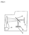
- FIG. 1 shows an embodiment of the focus detection device according to the present invention. The embodiment is described in reference to an example in which the focus detection device according to the present invention is adopted in a digital single lens reflex still camera.
- FIG. 1 shows the structure adopted in the optical system of the digital single lens reflex still camera.
- a light flux originating from the subject and transmitted through an image forming optical system 1 is then transmitted through a half mirror 2 and is guided to an image sensor 3 disposed at a predetermined focal plane of the image forming optical system 1.
- a subject image is thus formed on the light receiving surface of the image sensor 3.
- the image forming optical system 1 is represented by a single lens in the illustration, the image forming optical system actually includes an objective lens, a zooming lens, a focusing lens, an aperture and a lens drive device 6.
- the micro-lens array 4 includes a plurality of micro-lenses disposed in a two-dimensional array.
- An area sensor 5 is disposed in correspondence to the micro-lens array 4, and the light flux, having originated from the subject and entered the micro-lens array 4, passes through the micro-lens array 4 and enters the area sensor 5.
- the plane of the pupil of the image forming optical system 1 and the light receiving surface (predetermined focal plane) of the image sensor 3 assume an optically conjugate relation to the plane defined by the line connecting the vertices of the individual micro-lenses at the micro-lens array 4.
- FIG. 2 shows the structure of the focus detection device installed in the digital single lens reflex still camera shown in FIG. 1 .
- the digital single lens reflex still camera is configured by mounting an interchangeable lens barrel, which includes the image forming optical system 1, at a body.
- the micro-lens array 4 and the area sensor 5 in FIG. 1 constitute part of the focus detection device.
- an intrinsic pupil position data recording unit 11 constituted with a non-volatile memory, intrinsic pupil position data inherent to the image forming optical system 1 are recorded.
- a communication circuit 12 reads out pupil position data from the intrinsic pupil position data recording unit 11 and transmits the pupil position data thus read out to an arithmetic operation unit 14a within the body.
- reference positions measured in advance for the specific lens mounted via the interchangeable lens barrel, are recorded each in correspondence to one of the micro-lenses constituting the micro-lens array 4.
- Such a reference position may be the position of the optical axis of the corresponding micro-lens as described later or a pupil center projection position to be described later.
- the arithmetic operation unit 14a calculates a reference position at a given image forming optical system 1 in correspondence to each micro-lens 4a. Based upon that reference positions having been calculated at an arithmetic operation unit 14a, the arithmetic operation unit 14b selects light receiving elements from which focus detection light reception data are to be obtained, among a plurality of light receiving elements, each corresponding to one of the micro-lenses and calculates parallax data to be detailed later.
- a focus calculation unit 15 executes focus detection calculation through a split-pupil phase difference AF (autofocus) method based upon the parallax data having been calculated by the calculation unit 14b. It is to be noted that the communication circuit 12 described above is not required in a configuration in which the focus detection device is installed in a camera with an integrated lens.
- the micro-lens array 4 includes a plurality of micro-lenses 4a disposed in a staggered pattern, as shown in FIG. 3 .
- the parallax data based upon which the focusing condition at the image forming optical system 1 is ascertained, are obtained through calculation executed by selecting micro-lenses 4a in a zigzag pattern over two adjacent rows and using data output from light receiving elements 5a at the area sensor 5 corresponding to the selected micro-lenses 4a.
- the parallax data calculation is to be described in detail later.
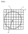
- FIG. 4 shows the relationship between a micro-lens 4a and light receiving elements 5a at the area sensor 5 in a plan view of a plane perpendicular to the normal passing through the vertex of the micro-lens 4a, i.e., perpendicular to the optical axis 4b of the micro-lens 4a.
- a circle S1 in FIG. 4 defines the shape of a shadow formed as the micro-lens 4a is projected onto the light receiving surface of the area sensor 5 along its optical axis 4b.
- the optical axis 4b of the micro-lens 4a and the center of a light receiving element 5a at the area sensor 5 cannot easily be set in perfect alignment relative to each other during the manufacturing process and rather, an offset such as that shown in FIG.
- the optical axis 4b is offset to a right/upward position along a diagonal direction relative to the center of a light receiving element 5a. Since the quantity of micro-lenses 4a and the array pattern assumed for the micro-lenses 4a at the micro-lens array 4 are known, the position of the point at which the optical axis 4b of the micro-lens 4a and the light receiving element 5a intersect each other (the position of the optical axis 4b of the micro-lens 4a) can be determined based upon the available information.
- the light receiving surface of the area sensor 5 assumes a position that is optically conjugate with the plane of the pupil of the image forming optical system 1 with respect to the micro-lens 4a, and an image of the pupil is projected onto the light receiving surface.
- the circle S1 defines an optically effective area of the micro-lens 4a.
- the outputs from the individual light receiving elements 5a corresponding to the micro-lens 4a each indicate the intensity of a light flux having passed through a specific area of the pupil of the image forming optical system 1.
- the parallax data to be described later are obtained based upon the outputs from the light receiving elements 5a corresponding to the micro-lens 4a.
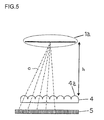
- FIG. 5 shows the relationship of the micro-lens array 4 and the area sensor 5 to the pupil 1a of the image forming optical system 1.
- the one-point chain lines C in FIG. 5 each connect the center of the pupil 1a with the vertex of a micro-lens 4a. In other words, the center of the pupil 1a is projected at the intersecting point at which the light receiving surface and each one-point chain line C intersect each other.
- the focus detection device In reality, it is also difficult to manufacture the focus detection device by setting the optical axes 4b of the micro-lenses 4a in perfect alignment with the optical axis of the image forming optical system 1. Accordingly, even assuming that the optical axes 4b of the micro-lenses 4a are aligned with the centers of light receiving elements 5a, it cannot be reliably ensured that the center of the pupil 1a is projected onto the centers of the light receiving elements 5a. Furthermore, the position at which the center of the pupil 1a is projected is altered in correspondence to the distance (hereafter referred to as the pupil position) h to the pupil 1a from the plane formed with the vertices of the individual micro-lenses 4a.
- the pupil position the distance
- the central position of an image of the pupil 1a projected onto the light receiving surface of the area sensor 5, i.e., a pupil center projection position, is calculated in correspondence to the pupil position h mentioned above and focus detection light reception data are sliced out based upon the calculation results.
- the intrinsic pupil position data recording unit 11 shown in FIG. 2 data indicating the pupil position h shown in FIG. 5 or data based upon which the pupil position h can be calculated are recorded. The following description is given by assuming that the pupil position h is recorded.
- the corresponding pupil center projection position is determined for each micro-lens 4a.
- the optical axis position recording unit 13 a set of data made up with data indicating the pupil center projection positions for the individual micro-lenses 4a is recorded in correspondence to each of a plurality of pupil positions h.
- One of the plurality of pupil positions h h 1 , h 2 , h 3 , ... may represent infinity.
- (x 1 , y 1 ) represents the coordinates of the pupil center projection position measured when the pupil position h is h 1
- (x 2 , y 2 ) represents the coordinates of the pupil center projection position measured when the pupil position h is h 2
- a method that may be adopted when calculating the coordinates (x 1 , y 1 ), (x 2 , y 2 ) ... indicating the pupil center projection positions, to be recorded in the optical axis position recording unit 13, is to be described later.
- x 1 , x 2 , and x 0 respectively assume linear relations to 1/h 1 , 1/h 2 and 1/h 0
- x 0 relative to 1/h 0 can be calculated as expressed in (1) based upon x 1 , x 2 , 1/h 1 and 1/h 2 .
- y 0 can be calculated as expressed in (2).
- the granularity of the data indicating the pupil center projection positions must be smaller than the size of light receiving elements 5a.
- the size of a single light receiving element 5a may be greater than the sum of the dimensions of two adjacent micro-lenses 4a. Accordingly, it is desirable that the data indicating the pupil center projection positions be expressed with values, the number of digits thereof greater by two digits or the like than the number of digits in the coordinate values, which are integers indicating the positions of the light receiving elements 5a.
- the coordinates (x 1 , y 1 ) and (x 2 , y 2 ) indicating the pupil center projection positions can be calculated based upon measurement data with greater ease when a greater aperture value, e.g., F22, is selected and thus the image of the projected pupil 1a is smaller.
- a light flux departing an illuminated white diffusing surface is received at the light receiving elements 5a via the micro-lenses 4a and image data I 1 are obtained based upon the light reception data.
- the light receiving surface of the area sensor 5 is conjugate with the pupil plane relative to the micro-lenses 4a and accordingly, the pupil image is projected onto the light receiving surface of the area sensor 5 and the corresponding image data are obtained.
- the lens focal length is 100 mm
- the focal length of the micro-lenses 4a is 100 ⁇ m
- pupil images with a diameter of 4.5 ⁇ m, the number of which corresponds to the quantity of micro-lenses 4a are projected onto the light receiving surface.
- the size of these pupil images is not much different from the size of pixels arrayed at a standard image sensor.
- image data I 2 are obtained in a similar manner under dark conditions by turning off the illumination on the diffusing surface.
- the output difference between the two types of image data I 1 and I 2 thus obtained constitutes image data I from which any influence of background noise such as noise attributable to the dark current is eliminated.
- the image data I include image data P(x, y) output at a position indicated by the coordinates (x, y).
- the coordinates (m, n) indicating the position of the optical axis 4b of a given micro-lens 4a may be designated as values hypothetically representing the coordinates (x pm , y pn ) of the pupil center projection position.
- R represents the integer part of the value obtained by dividing the radius of the micro-lens 4a by the length of a side of a light receiving element 5a.
- the x coordinate of the position of the gravitational center of the pupil image projected onto the light receiving surface can be expressed as in (3) below.
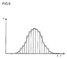
- the y-coordinate of the position of the gravitational center of the pupil image projected on the light receiving surface can likewise be expressed in a manner similar to that in (3) and the integrating operation is executed over a square area assuming a length 2R for each side and centered on the point indicated by the coordinates (x pm , y pn ). Since the position of a light receiving element 5a is indicated by discrete coordinate values, the position of the gravitational center of the corresponding pupil image can be determined based upon a histogram pertaining to the outputs P from the light receiving elements 5a, such as that in FIG. 6 .
- the coordinates (x0 pm , y0 pn ) indicating the position of the gravitational center of the pupil image can be expressed as in (4) and (5) below.
- the coordinates (m, n) initially used for substitution for the coordinates (x pm , y pn ) of the pupil center projection position in expressions (4) and (5) are hypothetical coordinate values and their accuracy is uncertain.
- the coordinates (x0 pm , y0 pn ) of the position of the gravitational center of the pupil image calculated as expressed in (4) and (5) as new hypothetical coordinate values for the coordinates (x pm , y pn ) of the pupil center projection position, the coordinates can be likewise expressed as in (6) and (7) below.
- the final coordinate values indicating the position of the gravitational center of the pupil image thus calculated are then designated as the coordinates (x pm , y pn ) of the pupil center projection position.
- a pair of sets of focus detection light reception data are sliced out by selecting a pair of pixels or a pair of pixel groups set apart from each other over a predetermined distance along the left/right (horizontal) direction, the up/down (vertical) direction or a diagonal direction, relative to a pupil center projection position having been sliced out as described above or the position of the optical axis 4b of a micro-lens 4a. Based upon the pair of sets of focus detection light reception data having been sliced out at the two positions, parallax data are obtained. As is to be described in reference to FIG.
- FIG. 7 illustrates how parallax data may be extracted.
- a circle S2 in FIG. 7 indicates an optically effective area of the micro-lens 4a and the light receiving elements 5a present within the circle S2 are covered with the micro-lens 4a.
- the outputs from the light receiving elements 5a present within the circle S2 each indicate the intensity of a light flux having passed through a given area of the pupil of the image forming optical system 1.
- a pair of areas 7c from which parallax data are to be sliced out are set at the pair of positions 7b and 7b' assuming left/right symmetry related to the pupil center projection position 7a.
- (x 0 , y 0 ) represents the coordinates of the pupil center projection position 7a
- (x 0 + d, y 0 ) represents the coordinates of the center 7b of the area 7c present to the right of the pupil center projection position 7a
- (x 0 - d, y 0 ) represents the coordinates of the center 7b' of the area 7c present to the left of the pupil center projection position 7a.
- the pair of positions 7b and 7b' assuming left/right symmetry with respect to the pupil center projection position are not aligned with the centers of light receiving elements 5a, either.
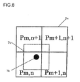
- An output P from the area 7c is calculated through proportional distribution of the outputs P m, n , P n + 1, n , P m, n + 1 and P m + 1, n + 1 corresponding to the plurality of light receiving elements 5a (a light receiving element group) present in the area 7c as shown in FIG. 8 .
- P' is calculated as expressed in (8)
- P" is calculated as expressed in (9).
- the output P is the output from the right-hand side area 7c in FIG. 7 .
- the output of the left-hand side area 7c can also be calculated through a similar arithmetic operation.
- the outputs of areas 7c set along the vertical direction relative to the pupil center projection position 7a can also be calculated through a similar arithmetic operation.
- parallax data are calculated for the positions 7b and 7b' offset to the left and to the right relative to the pupil center projection position 7a in correspondence to a single micro-lens 4a. Similar arithmetic operations are executed for w micro-lenses 4a arrayed along the baseline. The batch of parallax data calculated for positions offset to the left is used as a left data string and the batch of parallax data calculated for positions offset to the right is used as a right data string. If the micro-lenses 4a are disposed in a staggered array, as shown in FIG.
- optimal micro-lenses 4a should be selected so as to obtain through calculation parallax data in correspondence to positions offset to the left and to the right relative to the selected micro-lenses.
- the extent of offset of the focal point from the predetermined focal plane is reflected in the parallax data.
- the curves individually plotted based upon the left and right data strings calculated in correspondence to the w micro-lenses 4a manifest a shift between the data string A and the data string B by the extent of which corresponds to the parallax.
- the shift quantity indicating the extent of shift manifested by the phases of the left and right data strings is determined through the focus detection calculation.
- the focus detection calculation executed by the focus calculation unit 15 shown in FIG. 2 is now described.
- the difference between the data string A and the data string B is calculated while shifting the phases of the two data strings A and B and the shift amount indicating the extent of shift between the phases when the difference is at its smallest is determined.
- the shift amount k at which the defocus amount D k is at its smallest is determined by altering the shift amount k as expressed in (11) below.
- D k ⁇ j a j + k - b j
- the defocus amount D k calculated as expressed in (11) assumes discrete values and its minimum value cannot be determined with a resolution the level of which is equal to or less than the intervals over which the micro-lenses 4a are disposed. Since the outputs of the data strings A and B are obtained as a composition of sine wave signals, D k calculated as expressed in (11) can be modified to represent D( ⁇ ) in expression (12) with ⁇ representing the phase difference ⁇ equivalent to the phase shift amount k by focusing on sine wave signals corresponding to a given spatial frequency ⁇ among these sine wave signals.
- Expression (12) can be rewritten as expression (13).
- D ⁇ K ⁇ sin ⁇ x + ⁇ - sin ⁇ x ⁇ dx
- D ⁇ K ⁇ ⁇ sin ⁇ / 2 ⁇ cos 2 ⁇ ⁇ x / 2 + ⁇ / 2
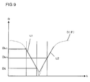
- D( ⁇ ) calculated as expressed in (13) changes in correspondence to the absolute value of the sine wave as indicated in FIG. 9 .
- D( ⁇ ) can be calculated in a similar manner when the spatial frequency ⁇ assumes another value.
- the defocus amount can be considered to assume the smallest value at the intersecting point of straight lines L1 and L2 described below, sloping with left-right symmetry, as shown in FIG. 9 .
- the smallest value D min of the defocus quantity can be calculated as follows.
- the smallest value of D k expressed in (11) and the corresponding phase shift quantity k are determined.
- the larger value of the two values D i - 1 and D i + 1 , closest to the smallest value D i assumed for D k is selected and the corresponding phase shift quantity k is also selected.
- the area sensor 5 with a plurality of light receiving elements 5a uniformly arrayed in correspondence to each micro-lens 4a is utilized and thus, the length of the baseline, extending along the left/right (horizontal) direction, the up/down (vertical) direction or a diagonal direction, can be adjusted.
- This feature will be extremely useful during focusing operation.
- the dynamic range of the focus detection can be increased by assuming a shorter baseline, the shorter baseline reduces the accuracy of the focus detection, whereas a longer baseline, which will improve the focus detection accuracy, will reduce the dynamic range of the focus detection.
- focus detection operation in a camera is executed by calculating the state of focus adjustment and driving the focusing lens multiple times until the focusing lens is driven to the focusing position rather than through a single calculation of the state of focus adjustment and a single focus adjustment drive.
- the baseline length is adjustable, a wide dynamic range can be assured by setting a smaller baseline length during the initial stage of the focus detection operation and then better accuracy can be assured as the focusing lens approaches the focusing position by gradually increasing the baseline length.
- a focus detection operation which ensures both high accuracy and a wide dynamic range can be executed.
- the digital single lens reflex still camera that executes split-pupil phase difference AF by engaging the focus detection device in the embodiment constituted with the micro-lens array 4 and the area sensor 5
- data indicating the reference positions i.e., the positions of the optical axes 4b of the individual micro-lenses 4a or the pupil center projection positions 7a corresponding to the individual micro-lenses 4a
- a reference position is calculated for each micro-lens 4a in correspondence to a given pupil position based upon the pupil position data recorded in the intrinsic pupil position data storage unit 11 and the reference position data, and parallax data are obtained based upon the reference position thus calculated.
- the micro-lens array 4 and the area sensor 5 do not need to be positioned with exacting precision, the focus detection device can be assembled with better ease.
- a pair of light receiving elements is selected in correspondence to each micro-lens 4a among the plurality of light receiving elements 5a at the area sensor 5 and the focusing condition of the optical system is determined through arithmetic operation executed based upon the outputs from the groups of light receiving elements selected in correspondence to a plurality of micro-lenses 4a.
- light receiving elements 5a can be selected with a high level of freedom and also, since the sums of outputs from a plurality of light receiving elements 5a can be used in the focus detection calculation, the focus detection accuracy is improved.
- position (pupil position) data indicating the position of the pupil of the optical system assured along the optical axis
- the corresponding pupil center projection position data are recorded and the necessary pupil center projection position data are generated through interpolation executed based upon the pupil position data and the pupil center projection position data.
- the positions of the optical axes 4b of all the micro-lenses 4a at the micro-lens array 4 are recorded
- the positions of the optical axes 4b of only some of the micro-lenses 4a may be recorded and, in such a case, the positions of the optical axes 4b of the other micro-lenses 4a may be determined through interpolation.
- the positions of the optical axes 4b of micro-lenses 4a present over predetermined intervals may be stored and the positions of the optical axes 4b of the micro-lenses 4a present in between may each be determined through interpolation executed based upon the positions of the optical axes 4b of the micro-lenses 4a adjacent on the left and right sides.
- the projection center position 7a does not need to be recorded in correspondence to each micro-lens 4a, either and, instead, only some projection center positions 7a may be recorded. In the latter case, the remaining projection center positions 7a can be determined through interpolation.
- parallax data are obtained through arithmetic operation by proportionally distributing the outputs from the light receiving elements 5a selected in correspondence to the individual micro-lenses 4a and the focusing condition of the image forming optical system 1 is calculated based upon the parallax data, assuring improved focus detection accuracy.
- the present invention may be adopted to achieve advantages comparable to those described above in a focus detection device constituted with a micro-lens array 4 made up with a plurality of micro-lenses 4a disposed in a single orderly row and an area sensor 5 made up with a plurality of light receiving elements 5a disposed in a single orderly row.
- the present invention may also be adopted in an image sensor engaged in both imaging operation and focus detection operation, which includes focus detection light receiving elements 5a disposed in a single row or a plurality of rows amidst a two-dimensional array of imaging light receiving elements.
- While the focus detection is executed based upon the outputs from the light receiving elements 5a disposed in correspondence to each micro-lens 4a, an image may be generated by using these outputs as well. Based upon the image thus generated, a person's face may be detected so as to select a focus detection area corresponding to the person's face among a plurality of focus detection areas or based upon the image, the photographic scene may be analyzed so as to execute the optimal processing corresponding to the scene.
- a specific range within the image generated as described above may be set as a focus detection area and the focusing condition may be detected based upon the outputs from the light receiving elements 5a corresponding to the micro-lenses 4a present within the focus detection area.
- Such a specific range within the image, to be set as a focus detection area may be, for example, an area corresponding to a characteristic area detected in the image, an area in the vicinity of a preselected focus detection position or an area set at a position where the contrast of the image is detected to be equal to or greater than a predetermined value.
- an image may be generated by using the outputs from the light receiving elements 5a corresponding to the individual micro-lenses 4a and thus, the area sensor 5 equipped with the micro-lens array 4 can also function as an image sensor in an imaging device that synthesizes an image (see, for instance, Japanese Laid Open Patent Publication No. 2007-4471 ).
- an imaging device that synthesizes images may be, for instance, a plenoptic camera or an image synthesizing camera.
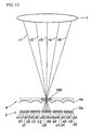
- FIGS. 10 and 11 illustrates how images may be synthesized by using light reception data from the area sensor 5 in conjunction with the micro-lens array 4.
- Z indicates the height measured from the vertices of the micro-lenses 4a to the specified image plane.
- the smallest units of image data resulting from the synthesis referred to as virtual pixels, are indicated by the dotted lines.
- the width of the virtual pixels matches the pitch at which the micro-lenses 4a are disposed.
- Light rays r1, r2, r3, r4 and r5 depart from different pupil areas of the image forming optical system 1.
- the light rays r1, r2, r3, r4 and r5 form an image at a virtual pixel 100 and then enter light receiving elements 5a via the corresponding micro-lens 4a.
- FIG. 1 In the example presented in FIG. 1
- the position of the virtual pixel 100 at which the image is formed is aligned with the plane ranging along a line connecting the vertices of the individual micro-lenses 4a, and the light rays r1, r2, r3, r4 and r5 respectively enter light receiving elements a3, b3, c3, d3 and e3 covered by the particular micro-lens 4a.
- image data are obtained by taking the sum of the outputs from five light receiving elements, i.e., the light receiving elements a3, b3, c3, d3 and e3 or the light receiving elements a1, b2, c3, d4 and e5, disposed along a single direction in the description provided above, it is necessary in reality to take the sum of the outputs from a total of 25, i.e., 5 (across) x 5 (down), light receiving elements in order to obtain image data on an image plane.
- the example presented in FIG. 10 is further elaborated in reference to FIG. 12 based upon this concept.
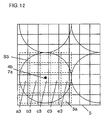
- FIG. 12 shows the relationship between micro-lenses 4a and light receiving elements 5a at the area sensor 5, in a plan view of a plane ranging perpendicular to the normal lines at the vertices of the micro-lenses 4a, i.e., perpendicular to the optical axes 4b of the micro-lenses 4a. While FIG. 3 shows micro-lenses 4a disposed in a staggered array, FIG. 12 shows micro-lenses 4a arrayed in straight rows for simplification. A circle S2 in FIG. 12 defines the shadow formed as a micro-lens 4a is projected onto the light receiving surface of the area sensor 5 along its optical axis 4b.
- the optical axis 4b of the micro-lens 4a is not aligned with the center of a light receiving element 5a at the area sensor 5 and in the example presented in FIG. 12 , the optical axis 4b is offset upward to the right along a diagonal direction relative to the center of a light receiving element 5a.
- normalized light receiving elements 7d selected through the processing described earlier in reference to the optical axis 4b of the micro-lens 4a are each indicated as a rectangular area defined by dotted lines and they assume positions offset upward to the right along a diagonal direction relative to the actual light receiving elements 5a.
- the outputs of the normalized light receiving elements 7d are calculated as expressed in (10), as are the outputs corresponding to the area 7c in FIG. 7 .
- image data can be obtained as the sum of the outputs from a total of 25 normalized light receiving elements 7d.
- FIG. 10 image data can be obtained as the sum of the outputs from a total of 25 normalized light receiving elements 7d.
- image data can be obtained in a similar manner by taking the sum of the outputs of the normalized light receiving elements 7d corresponding to a plurality of relevant micro-lenses 4a. While a description is given above by assuming that the optical axes 4b of the micro-lenses 4a are designated as the reference positions, the pupil center projection positions 7a may instead be designated as the reference positions.
- the present invention may be adopted in a camera with an integrated lens having a body and an image forming optical system constituted as an integrated unit.
- the image forming optical system 1 does not need to be a fixed focal length lens and it may be a zoom lens, the pupil position of which changes in correspondence to the focal length.
Landscapes
- Physics & Mathematics (AREA)
- Engineering & Computer Science (AREA)
- General Physics & Mathematics (AREA)
- Multimedia (AREA)
- Signal Processing (AREA)
- Computer Vision & Pattern Recognition (AREA)
- Optics & Photonics (AREA)
- Focusing (AREA)
- Transforming Light Signals Into Electric Signals (AREA)
- Automatic Focus Adjustment (AREA)
- Solid State Image Pick-Up Elements (AREA)
Abstract
Description
- The present invention relates to a light receiving element, a focus detection device and an imaging device.
- There is a focus detection device known in the related art that includes a micro-lens array disposed at a predetermined focal plane of an image forming optical system and a plurality of light receiving elements disposed in a linear pattern in correspondence to each micro-lens, creates a pair of signal value strings made up with signal values output from the light receiving elements disposed below the micro-lenses, which correspond to a pair of areas of the pupil of the image forming optical system, and detects the focusing condition at the image forming optical system by detecting the shift amount manifested by the pair of signal value strings (see patent literature 1).
- Patent Literature 1: Japanese Laid Open Patent Publication No.
2007-11314 - When manufacturing a focus detection device by layering an area sensor with light receiving elements arrayed in an orderly two-dimensional pattern and a micro-lens array one on top of the other, the center of each micro-lens and the center of a light receiving element corresponding to the micro-lens cannot easily be aligned with accuracy in the submicron order. Rather, since a stable positional relationship cannot be assured reliably for the micro-lens array and the area sensor, highly accurate focus detection cannot always be executed.
- According to the 1st aspect of the present invention, a light receiving device that receives light having passed through an image forming optical system and outputs a light reception signal comprises: a light receiving element array formed by arraying a plurality of light receiving elements; a micro-lens array disposed between the image forming optical system and the light receiving element array, which includes a plurality of micro-lenses arrayed in correspondence to the plurality of light receiving elements; and a storage unit that stores position-related information pertaining to a relative positional relationship assumed by the micro-lens array and the light receiving element array with respect to a plane perpendicular to optical axes of the micro-lenses.
According to the 2nd aspect of the present invention, in the light receiving device according to the 1st aspect, it is preferred that the position-related information relates to positions assumed by the optical axes of the micro-lenses on the light receiving element array.
According to the 3rd aspect of the present invention, in the light receiving device according to the 1st aspect, it is preferred that the position-related information indicates a relationship pertaining to the image forming optical system assuming a first pupil position, achieved between central positions of pupil images projected via the micro-lenses onto the light receiving element array and the first pupil position.
According to the 4th aspect of the present invention, in the light receiving device according to the 3rd aspect, it is preferred that the position-related information further indicates a relationship pertaining to the image forming optical system assuming a second pupil position different from the first pupil position, achieved between central positions of pupil images projected via the micro-lenses onto the light receiving element array and the second pupil position.
According to the 5th aspect of the present invention, in the light receiving device according to the 4th aspect, it is preferred that the position-related information is constituted with a set of data indicating the first pupil position and the central positions of the pupil images corresponding to the first pupil position.
According to the 6th aspect of the present invention, in the light receiving device according to the 4th aspect, it is preferred that the light receiving device further comprises: a position calculation unit that determines, based upon the position-related information, the central positions of pupil images corresponding to a given pupil position that may be assumed by the image forming optical system.
According to the 7th aspect of the present invention, in the light receiving device according to the 6th aspect, it is preferred that with (x1, y1) and (x2, y2) respectively representing central positions of the pupil images corresponding to the first pupil position h1 and the second pupil position h2 and h0 representing the given pupil position, the position calculation unit calculates a central position (x0, y0) representing each of the central positions of the pupil images corresponding to the given pupil position h0 expressed as;

According to the 8th aspect of the present invention, a focus detection device comprises: a light receiving device according to the 1st aspect; a selection unit that selects a group of light receiving elements from a plurality of light receiving elements corresponding to at least some of the plurality of micro-lenses by designating as a reference position a relative positional relationship, pertaining to a plane perpendicular to the optical axes of the micro-lenses, and achieved between the micro-lenses and the light receiving element array, which is determined based upon the position-related information for the at least some of the plurality of micro-lenses; and a focus detection calculation unit that detects a focusing condition of the image forming optical system based upon outputs from the group of light receiving elements having been selected by the selection unit.
According to the 9th aspect of the present invention, in the focus detection device according to the 8th aspect, it is preferred that the focus detection device further comprises: a normalization unit that normalizes, based upon the position-related information, the outputs from the group of light receiving elements having been selected by the selection unit, and that the focus detection calculation unit detects the focusing condition based upon the outputs having been normalized by the normalization unit.
According to the 10th aspect of the present invention, in the focus detection device according to the 9th aspect, it is preferred that the normalization unit normalizes the outputs of the group of light receiving elements having been selected by the selection unit based upon the position-related information through weighted averaging; and the focus detection calculation unit detects the focusing condition of the image forming optical system based upon the outputs having been normalized through the weighted averaging.
According to the 11th aspect of the present invention, in the focus detection device according to the 8th aspect, it is preferred that the group of light receiving elements having been selected by the selection unit includes at least two light receiving elements.
According to the 12th aspect of the present invention, in the focus detection device according to the 8th aspect, it is preferred that the selection unit selects as the group of light receiving elements a pair of light receiving element groups centered on the reference position as which a position of each of the optical axes of the micro-lenses assumed on the light receiving element array is designated.
According to the 13th aspect of the present invention, in the focus detection device according to the 12th aspect, it is preferred that the focus detection device further comprises: an ascertaining unit that ascertains a pupil position assumed by the image forming optical system; and a correction unit that corrects the position of the optical axis based upon the pupil position ascertained by the ascertaining unit.
According to the 14th aspect of the present invention, in the focus detection device according to the 11th aspect, it is preferred that the selection unit selects as the group of light receiving elements a pair of light receiving element groups centered on the reference position as which a central position of an image of a pupil of the image forming optical system, projected via each of the micro-lenses onto the light receiving element array, is designated.
According to the 15th aspect of the present invention, in the focus detection device according to the 12th or 14th aspect, that repeatedly detects the focusing condition by altering a distance between the pair of light receiving element groups.
According to the 16th aspect of the present invention, an imaging device comprises: a focus detection device according to any one of the 8th through 15th aspects; and an image sensor that receives a light flux from a subject and outputs an image signal, and the image forming optical system guides the light flux from the subject to the image sensor and the focus detection device.
According to the 17th aspect of the present invention, in the imaging device according to the 16th aspect, it is preferred that the image forming optical system includes a focusing lens and a lens drive device that drives the focusing lens along an optical axis of the image forming optical system based upon the focusing condition detected by the focus detection device.
According to the 18th aspect of the present invention, an imaging device comprises: a light receiving device according to the 1st aspect; and an image synthesis unit that synthesizes image data expressing an image at a given image plane assumed by the image forming optical system based upon outputs from some light receiving elements selected from the plurality of light receiving elements disposed in correspondence to each of the micro-lenses by designating as a reference position a relative positional relationship pertaining to a plane perpendicular to the optical axes of the micro-lenses and achieved between the micro-lenses and the light receiving array, which is determined for each micro-lens based upon the position-related information.
According to the 19th aspect of the present invention, in the imaging device according to the 18th aspect, it is preferred that the imaging device further comprises: a normalization unit that normalizes based upon the position-related information the outputs from the some light receiving elements having been selected, and that the image synthesis unit synthesizes the image data based upon the outputs having been normalized by the normalization unit. - According to the present invention, focus detection can be executed with a high level of accuracy without requiring the micro-lens array and the area sensor to be aligned with exacting precision.
-
- (
FIG. 1 ) A figure of the structure of an optical system in a camera equipped with the focus detection device achieved in an embodiment of the present invention; - (
FIG. 2 ) A figure of the structure of the focus detection device; - (
FIG. 3 ) A figure of the array pattern with which the micro-lenses are arrayed; - (
FIG. 4 ) A figure of the positional relationship between themicro-lens 4a and light receivingelements 5a at thearea sensor 5; - (
FIG. 5 ) A figure of the positional relationship of the pupil 1a of the image formingoptical system 1 to themicro-lens array 4 and thearea sensor 5; - (
FIG. 6 ) A figure of a histogram of the signal values P indicated by the signals output from the light receiving elements; - (
FIG. 7 ) An illustration of parallax data extraction target areas; - (
FIG. 8 ) An illustration of signal values P indicated by the signals output from an extraction target area; - (
FIG. 9 ) A figure of the relationship of the defocus amount Dk indicating the extent of defocusing relative to the shift amount k indicating an extent of shift manifested by the pair of signal value strings; - (
FIG. 10 ) An illustration of a method of photographic operation executed by using the signal values from the light receiving elements in an area sensor equipped with a micro-lens array when the position of a specified image plane is expressed as; Z = 0; - (
FIG. 11 ) An illustration of a method of photographic operation executed by using the signal values from the light receiving elements in an area sensor equipped with a micro-lens array when the position of a specified image plane is expressed as; Z = Z1; - (
FIG. 12 ) Figure of a positional relationship that may be assumed for the micro-lenses and the light receiving elements at the area sensor. - The following is a description of the best mode for carrying out the present invention, given in reference to the drawings.
FIG. 1 shows an embodiment of the focus detection device according to the present invention. The embodiment is described in reference to an example in which the focus detection device according to the present invention is adopted in a digital single lens reflex still camera.FIG. 1 shows the structure adopted in the optical system of the digital single lens reflex still camera. - A light flux originating from the subject and transmitted through an image forming
optical system 1 is then transmitted through a half mirror 2 and is guided to animage sensor 3 disposed at a predetermined focal plane of the image formingoptical system 1. A subject image is thus formed on the light receiving surface of theimage sensor 3. Theimage sensor 3, equipped with imaging pixels disposed in a two-dimensional array, receives a light flux from the subject, with which an image is formed via the image formingoptical system 1, and outputs image signals. It is to be noted that although the image formingoptical system 1 is represented by a single lens in the illustration, the image forming optical system actually includes an objective lens, a zooming lens, a focusing lens, an aperture and alens drive device 6. - Part of the light flux from the subject, having been transmitted through the image forming
optical system 1, is reflected at the half mirror 2 and is guided to amicro-lens array 4. Themicro-lens array 4 includes a plurality of micro-lenses disposed in a two-dimensional array. Anarea sensor 5 is disposed in correspondence to themicro-lens array 4, and the light flux, having originated from the subject and entered themicro-lens array 4, passes through themicro-lens array 4 and enters thearea sensor 5. - The plane of the pupil of the image forming
optical system 1 and the light receiving surface (predetermined focal plane) of theimage sensor 3 assume an optically conjugate relation to the plane defined by the line connecting the vertices of the individual micro-lenses at themicro-lens array 4. Thearea sensor 5, which is a light receiving element array of a plurality of light receiving elements disposed in a two-dimensional array, is disposed at the focal plane of the micro-lenses at themicro-lens array 4. Based upon focus detection signals output from the light receiving elements at thearea sensor 5, the extent of an offset of the position at which the image is formed via the image formingoptical system 1, relative to the predetermined focal plane, is measured and focus adjustment for the image formingoptical system 1 is executed based upon the measurement results. -
FIG. 2 shows the structure of the focus detection device installed in the digital single lens reflex still camera shown inFIG. 1 . The digital single lens reflex still camera is configured by mounting an interchangeable lens barrel, which includes the image formingoptical system 1, at a body. Themicro-lens array 4 and thearea sensor 5 inFIG. 1 constitute part of the focus detection device. In an intrinsic pupil positiondata recording unit 11 constituted with a non-volatile memory, intrinsic pupil position data inherent to the image formingoptical system 1 are recorded. Acommunication circuit 12 reads out pupil position data from the intrinsic pupil positiondata recording unit 11 and transmits the pupil position data thus read out to anarithmetic operation unit 14a within the body. In an optical axisposition recording unit 13, reference positions, measured in advance for the specific lens mounted via the interchangeable lens barrel, are recorded each in correspondence to one of the micro-lenses constituting themicro-lens array 4. Such a reference position may be the position of the optical axis of the corresponding micro-lens as described later or a pupil center projection position to be described later. - Based upon the reference positions recorded in the optical axis
position recording unit 13 and the intrinsic pupil position data pertaining to the image formingoptical system 1 recorded in the intrinsic pupil positiondata recording unit 11, thearithmetic operation unit 14a calculates a reference position at a given image formingoptical system 1 in correspondence to each micro-lens 4a. Based upon that reference positions having been calculated at anarithmetic operation unit 14a, thearithmetic operation unit 14b selects light receiving elements from which focus detection light reception data are to be obtained, among a plurality of light receiving elements, each corresponding to one of the micro-lenses and calculates parallax data to be detailed later. Afocus calculation unit 15 executes focus detection calculation through a split-pupil phase difference AF (autofocus) method based upon the parallax data having been calculated by thecalculation unit 14b. It is to be noted that thecommunication circuit 12 described above is not required in a configuration in which the focus detection device is installed in a camera with an integrated lens. - The
micro-lens array 4 includes a plurality of micro-lenses 4a disposed in a staggered pattern, as shown inFIG. 3 . The parallax data, based upon which the focusing condition at the image formingoptical system 1 is ascertained, are obtained through calculation executed by selecting micro-lenses 4a in a zigzag pattern over two adjacent rows and using data output fromlight receiving elements 5a at thearea sensor 5 corresponding to the selected micro-lenses 4a. The parallax data calculation is to be described in detail later. -
FIG. 4 shows the relationship between a micro-lens 4a andlight receiving elements 5a at thearea sensor 5 in a plan view of a plane perpendicular to the normal passing through the vertex of the micro-lens 4a, i.e., perpendicular to theoptical axis 4b of the micro-lens 4a. A circle S1 inFIG. 4 defines the shape of a shadow formed as the micro-lens 4a is projected onto the light receiving surface of thearea sensor 5 along itsoptical axis 4b. Theoptical axis 4b of the micro-lens 4a and the center of alight receiving element 5a at thearea sensor 5 cannot easily be set in perfect alignment relative to each other during the manufacturing process and rather, an offset such as that shown inFIG. 4 tends to occur in correspondence to the relative positional relationship of themicro-lens array 4 and thearea sensor 5 in relation to a plane perpendicular to theoptical axis 4b. In the example presented inFIG. 4 , theoptical axis 4b is offset to a right/upward position along a diagonal direction relative to the center of alight receiving element 5a. Since the quantity of micro-lenses 4a and the array pattern assumed for the micro-lenses 4a at themicro-lens array 4 are known, the position of the point at which theoptical axis 4b of the micro-lens 4a and thelight receiving element 5a intersect each other (the position of theoptical axis 4b of the micro-lens 4a) can be determined based upon the available information. - The light receiving surface of the
area sensor 5 assumes a position that is optically conjugate with the plane of the pupil of the image formingoptical system 1 with respect to the micro-lens 4a, and an image of the pupil is projected onto the light receiving surface. As long as theoptical axis 4b of the micro-lens 4a inFIG. 4 is aligned with the optical axis of the image formingoptical system 1, the circle S1 defines an optically effective area of the micro-lens 4a. In such a case, the outputs from the individuallight receiving elements 5a corresponding to the micro-lens 4a each indicate the intensity of a light flux having passed through a specific area of the pupil of the image formingoptical system 1. - Assuming that the position of the
optical axis 4b of thespecific micro-lens 4a is designated as the reference position, the parallax data to be described later are obtained based upon the outputs from thelight receiving elements 5a corresponding to the micro-lens 4a. -
FIG. 5 shows the relationship of themicro-lens array 4 and thearea sensor 5 to the pupil 1a of the image formingoptical system 1. The one-point chain lines C inFIG. 5 each connect the center of the pupil 1a with the vertex of a micro-lens 4a. In other words, the center of the pupil 1a is projected at the intersecting point at which the light receiving surface and each one-point chain line C intersect each other. - In reality, it is also difficult to manufacture the focus detection device by setting the
optical axes 4b of the micro-lenses 4a in perfect alignment with the optical axis of the image formingoptical system 1. Accordingly, even assuming that theoptical axes 4b of the micro-lenses 4a are aligned with the centers oflight receiving elements 5a, it cannot be reliably ensured that the center of the pupil 1a is projected onto the centers of thelight receiving elements 5a. Furthermore, the position at which the center of the pupil 1a is projected is altered in correspondence to the distance (hereafter referred to as the pupil position) h to the pupil 1a from the plane formed with the vertices of the individual micro-lenses 4a. - It is desirable to slice out focus detection light reception data in reference to the coordinate values representing the intersecting point, in order to improve the accuracy of the focus detection. In the embodiment, the central position of an image of the pupil 1a projected onto the light receiving surface of the
area sensor 5, i.e., a pupil center projection position, is calculated in correspondence to the pupil position h mentioned above and focus detection light reception data are sliced out based upon the calculation results. In the intrinsic pupil positiondata recording unit 11 shown inFIG. 2 , data indicating the pupil position h shown inFIG. 5 or data based upon which the pupil position h can be calculated are recorded. The following description is given by assuming that the pupil position h is recorded. - Once the pupil position h is set to a specific value, the corresponding pupil center projection position is determined for each micro-lens 4a. In the optical axis
position recording unit 13, a set of data made up with data indicating the pupil center projection positions for theindividual micro-lenses 4a is recorded in correspondence to each of a plurality of pupil positions h. One of the plurality of pupil positions h = h1, h2, h3, ... may represent infinity. - The coordinates indicating the pupil center projection positions are measured in correspondence to the individual micro-lenses 4a in conjunction with, for instance, two different image forming systems assuming pupil positions h = h1 and h = h2. (x1, y1) represents the coordinates of the pupil center projection position measured when the pupil position h is h1, whereas, (x2, y2) represents the coordinates of the pupil center projection position measured when the pupil position h is h2. The sets of data may be recorded, for instance, prior to factory shipment into the optical axis
position recording unit 13 in correspondence to the pupil positions h = h1 and h = h2. A method that may be adopted when calculating the coordinates (x1, y1), (x2, y2) ... indicating the pupil center projection positions, to be recorded in the optical axisposition recording unit 13, is to be described later. - The
arithmetic operation unit 14a mentioned earlier calculates the pupil center projection position (x0, y0) corresponding to the pupil position h = h0 as expressed in (1) and (2) below, based upon the pupil position h recorded in the intrinsic pupil positiondata recording unit 11 for the image formingoptical system 1 and the pupil center projection positions (x1, y1) and (x2, y2) recorded in the optical axisposition recording unit 13. Based upon the hypothesis that x1, x2, and x0 respectively assume linear relations to 1/h1, 1/h2 and 1/h0, x0 relative to 1/h0 can be calculated as expressed in (1) based upon x1, x2, 1/h1 and 1/h2. Likewise, y0 can be calculated as expressed in (2).

- The granularity of the data indicating the pupil center projection positions must be smaller than the size of
light receiving elements 5a. For instance, the size of a singlelight receiving element 5a may be greater than the sum of the dimensions of twoadjacent micro-lenses 4a. Accordingly, it is desirable that the data indicating the pupil center projection positions be expressed with values, the number of digits thereof greater by two digits or the like than the number of digits in the coordinate values, which are integers indicating the positions of thelight receiving elements 5a. - The method adopted when calculating the pupil center projection positions (x1, y1) and (x2, y2) corresponding to the known pupil positions h = h1 and h = h2, to be recorded as sets of data into the optical axis
position recording unit 13, is now described. The coordinates (x1, y1) and (x2, y2) indicating the pupil center projection positions can be calculated based upon measurement data with greater ease when a greater aperture value, e.g., F22, is selected and thus the image of the projected pupil 1a is smaller. - A light flux departing an illuminated white diffusing surface is received at the
light receiving elements 5a via the micro-lenses 4a and image data I1 are obtained based upon the light reception data. As explained earlier, the light receiving surface of thearea sensor 5 is conjugate with the pupil plane relative to the micro-lenses 4a and accordingly, the pupil image is projected onto the light receiving surface of thearea sensor 5 and the corresponding image data are obtained. - For instance, when the aperture value setting is F22, the lens focal length is 100 mm, the pupil position h = h1 = 100 mm and the focal length of the micro-lenses 4a is 100µm, pupil images with a diameter of 4.5µm, the number of which corresponds to the quantity of micro-lenses 4a, are projected onto the light receiving surface. The size of these pupil images is not much different from the size of pixels arrayed at a standard image sensor.
- Next, image data I2 are obtained in a similar manner under dark conditions by turning off the illumination on the diffusing surface. The output difference between the two types of image data I1 and I2 thus obtained constitutes image data I from which any influence of background noise such as noise attributable to the dark current is eliminated. The image data I include image data P(x, y) output at a position indicated by the coordinates (x, y).
- For instance, when the pupil position h is hp, the coordinates (m, n) indicating the position of the
optical axis 4b of a givenmicro-lens 4a may be designated as values hypothetically representing the coordinates (xpm, ypn) of the pupil center projection position. R represents the integer part of the value obtained by dividing the radius of the micro-lens 4a by the length of a side of alight receiving element 5a. The x coordinate of the position of the gravitational center of the pupil image projected onto the light receiving surface can be expressed as in (3) below.
- The y-coordinate of the position of the gravitational center of the pupil image projected on the light receiving surface can likewise be expressed in a manner similar to that in (3) and the integrating operation is executed over a square area assuming a length 2R for each side and centered on the point indicated by the coordinates (xpm, ypn). Since the position of a
light receiving element 5a is indicated by discrete coordinate values, the position of the gravitational center of the corresponding pupil image can be determined based upon a histogram pertaining to the outputs P from thelight receiving elements 5a, such as that inFIG. 6 . The coordinates (x0pm, y0pn) indicating the position of the gravitational center of the pupil image can be expressed as in (4) and (5) below.

- The coordinates (m, n) initially used for substitution for the coordinates (xpm, ypn) of the pupil center projection position in expressions (4) and (5) are hypothetical coordinate values and their accuracy is uncertain. By designating the coordinates (x0pm, y0pn) of the position of the gravitational center of the pupil image calculated as expressed in (4) and (5), as new hypothetical coordinate values for the coordinates (xpm, ypn) of the pupil center projection position, the coordinates can be likewise expressed as in (6) and (7) below.


- The newer coordinates (x1pm, y1pn) indicating the position of the gravitational center of the pupil image are more reliable than (x0pm, y0pn). While (xpm, ypn) = (x1pm, y1pn) can be used as the values indicating the coordinates of the pupil center projection position under normal circumstances, a similar arithmetic operation may be executed repeatedly t times, or such an arithmetic operation may be repeatedly executed until the difference between the coordinate values calculated through the tth arithmetic operation and the coordinate values calculated through the (t + 1)th arithmetic operation becomes less that a predetermined value. The final coordinate values indicating the position of the gravitational center of the pupil image thus calculated are then designated as the coordinates (xpm, ypn) of the pupil center projection position. Coordinates (x1m, y1n) are calculated to indicate the pupil center projection position for the micro-lens 4a occupying the position indicated by the coordinates (m, n) in correspondence to the pupil position h = h1, whereas coordinates (x2m, y2n) are calculated to indicate the pupil center projection position for the micro-lens 4a occupying the position indicated by the coordinates (m, n) in correspondence to the pupil position h = h2.
- Sets of data {x1, y1} and {x2, y2} corresponding to the pupil positions h = h1 and h = h2, obtained by calculating the pupil center projection position coordinates for all the micro-lenses 4a as described above, are recorded into the optical axis
position recording unit 13. Then, based upon the pupil positions h = h1 and h = h2 and the sets of data {x1, y1} and {x2, y2}, the pupil center projection position (x0, y0) for each micro-lens 4a can be calculated as expressed in (1) and (2) in conjunction with a lens assuming the pupil position h. - A pair of sets of focus detection light reception data are sliced out by selecting a pair of pixels or a pair of pixel groups set apart from each other over a predetermined distance along the left/right (horizontal) direction, the up/down (vertical) direction or a diagonal direction, relative to a pupil center projection position having been sliced out as described above or the position of the
optical axis 4b of a micro-lens 4a. Based upon the pair of sets of focus detection light reception data having been sliced out at the two positions, parallax data are obtained. As is to be described in reference toFIG. 7 , either of the pair ofpositions center projection position 7a over a predetermined distance, is not necessarily aligned with the center of alight receiving element 5a and accordingly, normalized outputs are calculated through proportional distribution based upon the outputs from adjacentlight receiving elements 5a. While the following description is given by assuming that the reference position is the pupilcenter projection position 7a, the same principle applies when the reference position is represented by the position of theoptical axis 4b of the micro-lens 4a. -
FIG. 7 illustrates how parallax data may be extracted. A circle S2 inFIG. 7 indicates an optically effective area of the micro-lens 4a and thelight receiving elements 5a present within the circle S2 are covered with the micro-lens 4a. The outputs from thelight receiving elements 5a present within the circle S2 each indicate the intensity of a light flux having passed through a given area of the pupil of the image formingoptical system 1. A pair ofareas 7c from which parallax data are to be sliced out are set at the pair ofpositions center projection position 7a.FIG. 7 showsareas 7c assuming an areal size matching that of thelight receiving elements 5a, respectively centered on thepositions center projection position 7a over a predetermined distance, e.g., a distance corresponding to twolight receiving elements 5a. - (x0, y0) represents the coordinates of the pupil
center projection position 7a, (x0 + d, y0) represents the coordinates of thecenter 7b of thearea 7c present to the right of the pupilcenter projection position 7a and (x0 - d, y0) represents the coordinates of thecenter 7b' of thearea 7c present to the left of the pupilcenter projection position 7a. As shown inFIG. 7 , if the pupilcenter projection position 7a does not match the center of alight receiving element 5a, the pair ofpositions light receiving elements 5a, either. - A description is given in reference to
FIG. 8 by focusing on thearea 7c present to the right, the center thereof occupying the position indicated by the coordinates (x0 + d, y0). Assuming m = [x0 + d] and n = [y0] ([ ] indicating an integer), the coordinates indicating the positions of thelight receiving elements 5a present in thearea 7c are (m, n), (m + 1, n), (m, n + 1) nd m + 1, n + 1). - X = x0 + d and Y = y0 represent the coordinates of the position of the center of the
area 7c. An output P from thearea 7c is calculated through proportional distribution of the outputs Pm, n, Pn + 1, n, Pm, n + 1 and P m + 1, n + 1 corresponding to the plurality oflight receiving elements 5a (a light receiving element group) present in thearea 7c as shown inFIG. 8 . Through horizontal proportional distribution of P m,n, and Pm + 1, n, P' is calculated as expressed in (8), whereas through horizontal proportional distribution of P m, n + 1 and P m + 1, n + 1, P" is calculated as expressed in (9). Then, the normalized output P is calculated for thearea 7c through vertical proportional distribution of P' and P" executed as expressed in (10) below.


- The output P is the output from the right-
hand side area 7c inFIG. 7 . The output of the left-hand side area 7c can also be calculated through a similar arithmetic operation. The outputs ofareas 7c set along the vertical direction relative to the pupilcenter projection position 7a can also be calculated through a similar arithmetic operation. - Through the operation described above, parallax data are calculated for the
positions center projection position 7a in correspondence to asingle micro-lens 4a. Similar arithmetic operations are executed for w micro-lenses 4a arrayed along the baseline. The batch of parallax data calculated for positions offset to the left is used as a left data string and the batch of parallax data calculated for positions offset to the right is used as a right data string. If the micro-lenses 4a are disposed in a staggered array, as shown inFIG. 3 ,optimal micro-lenses 4a should be selected so as to obtain through calculation parallax data in correspondence to positions offset to the left and to the right relative to the selected micro-lenses. The left data string and the right data string thus obtained are respectively referred to as a data string A and a data string B, with each set of parallax data in the data string A indicated as aj and each set of parallax data in the data string B indicated as bj (j = 1, ...,w). - The extent of offset of the focal point from the predetermined focal plane is reflected in the parallax data. Namely, the curves individually plotted based upon the left and right data strings calculated in correspondence to the w micro-lenses 4a manifest a shift between the data string A and the data string B by the extent of which corresponds to the parallax. On the premise that the left data string and the right data string are obtained based upon substantially similar projection image data, the shift quantity indicating the extent of shift manifested by the phases of the left and right data strings is determined through the focus detection calculation.
- The focus detection calculation executed by the
focus calculation unit 15 shown inFIG. 2 is now described. In the focus detection calculation, the difference between the data string A and the data string B is calculated while shifting the phases of the two data strings A and B and the shift amount indicating the extent of shift between the phases when the difference is at its smallest is determined. Namely, the shift amount k at which the defocus amount Dk is at its smallest is determined by altering the shift amount k as expressed in (11) below.
- The defocus amount Dk calculated as expressed in (11) assumes discrete values and its minimum value cannot be determined with a resolution the level of which is equal to or less than the intervals over which the micro-lenses 4a are disposed. Since the outputs of the data strings A and B are obtained as a composition of sine wave signals, Dk calculated as expressed in (11) can be modified to represent D(θ) in expression (12) with θ representing the phase difference θ equivalent to the phase shift amount k by focusing on sine wave signals corresponding to a given spatial frequency ω among these sine wave signals. Expression (12) can be rewritten as expression (13).


- D(θ) calculated as expressed in (13) changes in correspondence to the absolute value of the sine wave as indicated in
FIG. 9 . D(θ) can be calculated in a similar manner when the spatial frequency ω assumes another value. Through approximation, the defocus amount can be considered to assume the smallest value at the intersecting point of straight lines L1 and L2 described below, sloping with left-right symmetry, as shown inFIG. 9 . - The smallest value Dmin of the defocus quantity can be calculated as follows. The smallest value of Dk expressed in (11) and the corresponding phase shift quantity k are determined. In the example presented in
FIG. 9 , Di corresponding to k = i is the smallest value assumed for Dk. The larger value of the two values Di - 1 and Di + 1, closest to the smallest value Di assumed for Dk, is selected and the corresponding phase shift quantity k is also selected. In the example presented inFIG. 9 , Di - 1 corresponding to k = i - 1 is selected. Then, the straight line L1 passing through two points indicated as (k, D) = (i, Di) and (k, D) = (i - 1, Di - 1) is drawn. Next, a straight line L2 passing through a point (k, D) = (i + 1, Di + 1), assuming a grade matching that of the straight line obtained by inverting the straight line L1 relative to the vertical coordinate axis, is drawn. Then, the intersecting point of the two straight lines L1 and L2 is determined and the value of D assumed at this intersecting point is designated as the minimum value Dmin. Through this operation, the position of the focal point can be calculated based upon the outputs from thelight receiving elements 5a in conjunction with themicro-lens array 4. - In the embodiment described above, the
area sensor 5 with a plurality oflight receiving elements 5a uniformly arrayed in correspondence to each micro-lens 4a is utilized and thus, the length of the baseline, extending along the left/right (horizontal) direction, the up/down (vertical) direction or a diagonal direction, can be adjusted. This feature will be extremely useful during focusing operation. Generally speaking, while the dynamic range of the focus detection can be increased by assuming a shorter baseline, the shorter baseline reduces the accuracy of the focus detection, whereas a longer baseline, which will improve the focus detection accuracy, will reduce the dynamic range of the focus detection. - Under normal circumstances, focus detection operation in a camera is executed by calculating the state of focus adjustment and driving the focusing lens multiple times until the focusing lens is driven to the focusing position rather than through a single calculation of the state of focus adjustment and a single focus adjustment drive. Thus, provided that the baseline length is adjustable, a wide dynamic range can be assured by setting a smaller baseline length during the initial stage of the focus detection operation and then better accuracy can be assured as the focusing lens approaches the focusing position by gradually increasing the baseline length. In other words, a focus detection operation which ensures both high accuracy and a wide dynamic range can be executed.
- As has been described, in the digital single lens reflex still camera that executes split-pupil phase difference AF by engaging the focus detection device in the embodiment constituted with the
micro-lens array 4 and thearea sensor 5, data indicating the reference positions, i.e., the positions of theoptical axes 4b of the individual micro-lenses 4a or the pupilcenter projection positions 7a corresponding to theindividual micro-lenses 4a, are stored in advance in the optical axisposition recording unit 13 within the body, a reference position is calculated for each micro-lens 4a in correspondence to a given pupil position based upon the pupil position data recorded in the intrinsic pupil positiondata storage unit 11 and the reference position data, and parallax data are obtained based upon the reference position thus calculated. As a result, better focus detection accuracy is assured. Since themicro-lens array 4 and thearea sensor 5 do not need to be positioned with exacting precision, the focus detection device can be assembled with better ease. - In the embodiment described above, a pair of light receiving elements is selected in correspondence to each micro-lens 4a among the plurality of
light receiving elements 5a at thearea sensor 5 and the focusing condition of the optical system is determined through arithmetic operation executed based upon the outputs from the groups of light receiving elements selected in correspondence to a plurality of micro-lenses 4a. Thus, when adopted in a configuration with numerouslight receiving elements 5a disposed in correspondence to each micro-lens 4a,light receiving elements 5a can be selected with a high level of freedom and also, since the sums of outputs from a plurality oflight receiving elements 5a can be used in the focus detection calculation, the focus detection accuracy is improved. - In the embodiment described above, position (pupil position) data, indicating the position of the pupil of the optical system assured along the optical axis, and the corresponding pupil center projection position data are recorded and the necessary pupil center projection position data are generated through interpolation executed based upon the pupil position data and the pupil center projection position data. As a result, a high level of focus detection accuracy can be maintained in conjunction with lenses having different specifications and different characteristics, e.g., varying focal lengths.
- While an explanation is given above in reference to the embodiment on an example in which the positions of the
optical axes 4b of all the micro-lenses 4a at themicro-lens array 4 are recorded, the positions of theoptical axes 4b of only some of the micro-lenses 4a may be recorded and, in such a case, the positions of theoptical axes 4b of the other micro-lenses 4a may be determined through interpolation. For instance, the positions of theoptical axes 4b of micro-lenses 4a present over predetermined intervals may be stored and the positions of theoptical axes 4b of the micro-lenses 4a present in between may each be determined through interpolation executed based upon the positions of theoptical axes 4b of the micro-lenses 4a adjacent on the left and right sides. In addition, theprojection center position 7a does not need to be recorded in correspondence to each micro-lens 4a, either and, instead, only someprojection center positions 7a may be recorded. In the latter case, the remainingprojection center positions 7a can be determined through interpolation. - In the embodiment described above, parallax data are obtained through arithmetic operation by proportionally distributing the outputs from the
light receiving elements 5a selected in correspondence to the individual micro-lenses 4a and the focusing condition of the image formingoptical system 1 is calculated based upon the parallax data, assuring improved focus detection accuracy. - While a description is given above in reference to the embodiment on an example in which the present invention is adopted in conjunction with a
micro-lens array 4 made up with a plurality of micro-lenses 4a arrayed in an orderly two-dimensional pattern and anarea sensor 5 made up with a plurality oflight receiving elements 5a disposed in an orderly two-dimensional pattern, the present invention may be adopted to achieve advantages comparable to those described above in a focus detection device constituted with amicro-lens array 4 made up with a plurality of micro-lenses 4a disposed in a single orderly row and anarea sensor 5 made up with a plurality oflight receiving elements 5a disposed in a single orderly row. - While the
area sensor 5 having been described in reference to the embodiment, which includes focus detectionlight receiving elements 5a that output focus detection light reception data disposed in a two-dimensional array, is used exclusively for focus detection, the present invention may also be adopted in an image sensor engaged in both imaging operation and focus detection operation, which includes focus detectionlight receiving elements 5a disposed in a single row or a plurality of rows amidst a two-dimensional array of imaging light receiving elements. - While the focus detection is executed based upon the outputs from the
light receiving elements 5a disposed in correspondence to each micro-lens 4a, an image may be generated by using these outputs as well. Based upon the image thus generated, a person's face may be detected so as to select a focus detection area corresponding to the person's face among a plurality of focus detection areas or based upon the image, the photographic scene may be analyzed so as to execute the optimal processing corresponding to the scene. - A specific range within the image generated as described above may be set as a focus detection area and the focusing condition may be detected based upon the outputs from the
light receiving elements 5a corresponding to the micro-lenses 4a present within the focus detection area. Such a specific range within the image, to be set as a focus detection area, may be, for example, an area corresponding to a characteristic area detected in the image, an area in the vicinity of a preselected focus detection position or an area set at a position where the contrast of the image is detected to be equal to or greater than a predetermined value. - As explained above, an image may be generated by using the outputs from the
light receiving elements 5a corresponding to the individual micro-lenses 4a and thus, thearea sensor 5 equipped with themicro-lens array 4 can also function as an image sensor in an imaging device that synthesizes an image (see, for instance, Japanese Laid Open Patent Publication No.2007-4471 - In image synthesis operation, a given image plane of the image forming
optical system 1 is designated as a specified image plane and image data expressing an image on the specified image plane are synthesized based upon the outputs from the individuallight receiving elements 5a.FIGS. 10 and11 illustrates how images may be synthesized by using light reception data from thearea sensor 5 in conjunction with themicro-lens array 4.FIG. 10 illustrates a method that may be adopted when synthesizing an image in conjunction with the specified image plane assuming a position expressed as Z = 0, whereasFIG. 11 illustrates a method that may be adopted when synthesizing an image in conjunction with the specified image plane assuming a position expressed as Z = Z1. Z indicates the height measured from the vertices of the micro-lenses 4a to the specified image plane. InFIGS. 10 and11 , the smallest units of image data resulting from the synthesis, referred to as virtual pixels, are indicated by the dotted lines. The width of the virtual pixels matches the pitch at which the micro-lenses 4a are disposed. - Light rays r1, r2, r3, r4 and r5 depart from different pupil areas of the image forming
optical system 1. The light rays r1, r2, r3, r4 and r5 form an image at avirtual pixel 100 and then enterlight receiving elements 5a via the correspondingmicro-lens 4a. In the example presented inFIG. 10 , the position of thevirtual pixel 100 at which the image is formed is aligned with the plane ranging along a line connecting the vertices of theindividual micro-lenses 4a, and the light rays r1, r2, r3, r4 and r5 respectively enter light receiving elements a3, b3, c3, d3 and e3 covered by theparticular micro-lens 4a. Image data corresponding to thevirtual pixel 100 at the specified image plane assuming the position Z = 0 can be obtained as the sum of the outputs from the light receiving elements a3, b3, c3, d3 and e3. Image data corresponding to other virtual pixels can likewise be obtained, each as the sum of the outputs of the light receiving elements covered by the correspondingmicro-lens 4a. With these image data, image data expressing an image formed at the specified image plane assuming the position Z = 0 are synthesized. - In the example presented in
FIG. 11 , the light rays r1, r2, r3, r4 and r5 form an image at avirtual pixel 100 at the specified image plane assuming the position Z = Z1 and then enter, viadifferent micro-lenses 4a, light receiving elements a1, b2, c3, d4 and e5 covered by thesemicro-lenses 4a. Image data corresponding to thevirtual pixel 100 at the specified image plane assuming the position Z = Z1 can be obtained as the sum of the outputs from the light receiving elements a1, b2, c3, d4 and e5. By executing similar processing for each virtual pixel, image data expressing an image formed at the specified image plane assuming the position Z = Z1 are synthesized. - While image data are obtained by taking the sum of the outputs from five light receiving elements, i.e., the light receiving elements a3, b3, c3, d3 and e3 or the light receiving elements a1, b2, c3, d4 and e5, disposed along a single direction in the description provided above, it is necessary in reality to take the sum of the outputs from a total of 25, i.e., 5 (across) x 5 (down), light receiving elements in order to obtain image data on an image plane. The example presented in
FIG. 10 is further elaborated in reference toFIG. 12 based upon this concept. -
FIG. 12 shows the relationship between micro-lenses 4a andlight receiving elements 5a at thearea sensor 5, in a plan view of a plane ranging perpendicular to the normal lines at the vertices of the micro-lenses 4a, i.e., perpendicular to theoptical axes 4b of the micro-lenses 4a. WhileFIG. 3 shows micro-lenses 4a disposed in a staggered array,FIG. 12 shows micro-lenses 4a arrayed in straight rows for simplification. A circle S2 inFIG. 12 defines the shadow formed as a micro-lens 4a is projected onto the light receiving surface of thearea sensor 5 along itsoptical axis 4b. As explained earlier, theoptical axis 4b of the micro-lens 4a is not aligned with the center of alight receiving element 5a at thearea sensor 5 and in the example presented inFIG. 12 , theoptical axis 4b is offset upward to the right along a diagonal direction relative to the center of alight receiving element 5a. - In
FIG. 12 , normalized light receiving elements 7d selected through the processing described earlier in reference to theoptical axis 4b of the micro-lens 4a are each indicated as a rectangular area defined by dotted lines and they assume positions offset upward to the right along a diagonal direction relative to the actuallight receiving elements 5a. The outputs of the normalized light receiving elements 7d are calculated as expressed in (10), as are the outputs corresponding to thearea 7c inFIG. 7 . In the example presented inFIG. 10 , image data can be obtained as the sum of the outputs from a total of 25 normalized light receiving elements 7d. In the example presented inFIG. 11 , image data can be obtained in a similar manner by taking the sum of the outputs of the normalized light receiving elements 7d corresponding to a plurality ofrelevant micro-lenses 4a. While a description is given above by assuming that theoptical axes 4b of the micro-lenses 4a are designated as the reference positions, the pupilcenter projection positions 7a may instead be designated as the reference positions. - While an explanation is given in reference to the embodiment on an example in which the present invention is adopted in a digital single lens reflex still camera with an interchangeable lens barrel mounted at the body thereof, the present invention may be adopted in a camera with an integrated lens having a body and an image forming optical system constituted as an integrated unit. In addition, the image forming
optical system 1 does not need to be a fixed focal length lens and it may be a zoom lens, the pupil position of which changes in correspondence to the focal length. - While embodiments and variations thereof are described above, the present invention is not limited to these examples and various modifications can be made without departing from the scope of the invention.
- The disclosures of the following priority applications are herein incorporated by reference:
- Japanese Patent Application No.
2007-258787 filed October 2, 2007 - Japanese Patent Application No.
2007-331854 filed December 25, 2007
Claims (19)
- A light receiving device that receives light having passed through an image forming optical system and outputs a light reception signal, comprising:a light receiving element array formed by arraying a plurality of light receiving elements;a micro-lens array disposed between the image forming optical system and the light receiving element array, which includes a plurality of micro-lenses arrayed in correspondence to the plurality of light receiving elements; anda storage unit that stores position-related information pertaining to a relative positional relationship assumed by the micro-lens array and the light receiving element array with respect to a plane perpendicular to optical axes of the micro-lenses.
- A light receiving device according to claim 1, wherein:the position-related information relates to positions assumed by the optical axes of the micro-lenses on the light receiving element array.
- A light receiving device according to claim 1, wherein:the position-related information indicates a relationship pertaining to the image forming optical system assuming a first pupil position, achieved between central positions of pupil images projected via the micro-lenses onto the light receiving element array and the first pupil position.
- A light receiving device according to claim 3, wherein:the position-related information further indicates a relationship pertaining to the image forming optical system assuming a second pupil position different from the first pupil position, achieved between central positions of pupil images projected via the micro-lenses onto the light receiving element array and the second pupil position.
- A light receiving device according to claim 4, wherein:the position-related information is constituted with a set of data indicating the first pupil position and the central positions of the pupil images corresponding to the first pupil position.
- A light receiving device according to claim 4, further comprising:a position calculation unit that determines, based upon the position-related information, the central positions of pupil images corresponding to a given pupil position that may be assumed by the image forming optical system.
- A light receiving device according to claim 6, wherein:with (x1, y1) and (x2, y2) respectively representing central positions of the pupil images corresponding to the first pupil position h1 and the second pupil position h2 and h0 representing the given pupil position, the position calculation unit calculates a central position (x0, y0) representing each of the central positions of the pupil images corresponding to the given pupil position h0 expressed as;

- A focus detection device, comprising:a light receiving device according to claim 1;a selection unit that selects a group of light receiving elements from a plurality of light receiving elements corresponding to at least some of the plurality of micro-lenses by designating as a reference position a relative positional relationship, pertaining to a plane perpendicular to the optical axes of the micro-lenses, and achieved between the micro-lenses and the light receiving element array, which is determined based upon the position-related information for the at least some of the plurality of micro-lenses; anda focus detection calculation unit that detects a focusing condition of the image forming optical system based upon outputs from the group of light receiving elements having been selected by the selection unit.
- A focus detection device according to claim 8, further comprising:a normalization unit that normalizes, based upon the position-related information, the outputs from the group of light receiving elements having been selected by the selection unit, wherein:the focus detection calculation unit detects the focusing condition based upon the outputs having been normalized by the normalization unit.
- A focus detection device according to claim 9, wherein:the normalization unit normalizes the outputs of the group of light receiving elements having been selected by the selection unit based upon the position-related information through weighted averaging; andthe focus detection calculation unit detects the focusing condition of the image forming optical system based upon the outputs having been normalized through the weighted averaging.
- A focus detection device according to claim 8, wherein:the group of light receiving elements having been selected by the selection unit includes at least two light receiving elements.
- A focus detection device according to claim 8, wherein:the selection unit selects as the group of light receiving elements a pair of light receiving element groups centered on the reference position as which a position of each of the optical axes of the micro-lenses assumed on the light receiving element array is designated.
- A focus detection device according to claim 12, further comprising:an ascertaining unit that ascertains a pupil position assumed by the image forming optical system; anda correction unit that corrects the position of the optical axis based upon the pupil position ascertained by the ascertaining unit.
- A focus detection device according to claim 11, wherein:the selection unit selects as the group of light receiving elements a pair of light receiving element groups centered on the reference position as which a central position of an image of a pupil of the image forming optical system, projected via each of the micro-lenses onto the light receiving element array, is designated.
- A focus detection device according to claim 12 or claim 14, that repeatedly detects the focusing condition by altering a distance between the pair of light receiving element groups.
- An imaging device, comprising:a focus detection device according to any one of claims 8 through 15; andan image sensor that receives a light flux from a subject and outputs an image signal, wherein:the image forming optical system guides the light flux from the subject to the image sensor and the focus detection device.
- An imaging device according to claim 16, wherein:the image forming optical system includes a focusing lens and a lens drive device that drives the focusing lens along an optical axis of the image forming optical system based upon the focusing condition detected by the focus detection device.
- An imaging device, comprising:a light receiving device according to claim 1; andan image synthesis unit that synthesizes image data expressing an image at a given image plane assumed by the image forming optical system based upon outputs from some light receiving elements selected from the plurality of light receiving elements disposed in correspondence to each of the micro-lenses by designating as a reference position a relative positional relationship pertaining to a plane perpendicular to the optical axes of the micro-lenses and achieved between the micro-lenses and the light receiving array, which is determined for each micro-lens based upon the position-related information.
- An imaging device according to claim 18, further comprising:a normalization unit that normalizes based upon the position-related information the outputs from the some light receiving elements having been selected, wherein:the image synthesis unit synthesizes the image data based upon the outputs having been normalized by the normalization unit.
Priority Applications (1)
| Application Number | Priority Date | Filing Date | Title |
|---|---|---|---|
| EP13175348.5A EP2651118B1 (en) | 2007-10-02 | 2008-10-01 | Light receiving device, focus detection device and imaging device |
Applications Claiming Priority (3)
| Application Number | Priority Date | Filing Date | Title |
|---|---|---|---|
| JP2007258787 | 2007-10-02 | ||
| JP2007331854 | 2007-12-25 | ||
| PCT/JP2008/067842 WO2009044776A1 (en) | 2007-10-02 | 2008-10-01 | Light receiving device, focal point detecting device and imaging device |
Related Child Applications (1)
| Application Number | Title | Priority Date | Filing Date |
|---|---|---|---|
| EP13175348.5A Division EP2651118B1 (en) | 2007-10-02 | 2008-10-01 | Light receiving device, focus detection device and imaging device |
Publications (2)
| Publication Number | Publication Date |
|---|---|
| EP2180362A1 true EP2180362A1 (en) | 2010-04-28 |
| EP2180362A4 EP2180362A4 (en) | 2011-03-30 |
Family
ID=40526201
Family Applications (2)
| Application Number | Title | Priority Date | Filing Date |
|---|---|---|---|
| EP08836715A Ceased EP2180362A4 (en) | 2007-10-02 | 2008-10-01 | Light receiving device, focal point detecting device and imaging device |
| EP13175348.5A Not-in-force EP2651118B1 (en) | 2007-10-02 | 2008-10-01 | Light receiving device, focus detection device and imaging device |
Family Applications After (1)
| Application Number | Title | Priority Date | Filing Date |
|---|---|---|---|
| EP13175348.5A Not-in-force EP2651118B1 (en) | 2007-10-02 | 2008-10-01 | Light receiving device, focus detection device and imaging device |
Country Status (4)
| Country | Link |
|---|---|
| US (1) | US8680451B2 (en) |
| EP (2) | EP2180362A4 (en) |
| JP (1) | JP5375010B2 (en) |
| WO (1) | WO2009044776A1 (en) |
Cited By (6)
| Publication number | Priority date | Publication date | Assignee | Title |
|---|---|---|---|---|
| CN103297683A (en) * | 2012-03-01 | 2013-09-11 | 佳能株式会社 | Image processing device and image processing method |
| WO2013167758A1 (en) * | 2012-05-11 | 2013-11-14 | Canon Kabushiki Kaisha | Micro lens array and imaging apparatus |
| US8767118B2 (en) | 2008-08-25 | 2014-07-01 | Canon Kabushiki Kaisha | Image sensing apparatus, image sensing system and focus detection method |
| CN105939471A (en) * | 2015-03-02 | 2016-09-14 | 佳能株式会社 | Image processing apparatus, image pickup apparatus and image processing method |
| US10097806B2 (en) | 2015-03-02 | 2018-10-09 | Canon Kabushiki Kaisha | Image processing apparatus, image pickup apparatus, image processing method, non-transitory computer-readable storage medium for improving quality of image |
| US11079607B2 (en) | 2010-06-16 | 2021-08-03 | Nikon Corporation | Image display device |
Families Citing this family (25)
| Publication number | Priority date | Publication date | Assignee | Title |
|---|---|---|---|---|
| US8680451B2 (en) | 2007-10-02 | 2014-03-25 | Nikon Corporation | Light receiving device, focus detection device and imaging device |
| JP5171468B2 (en) * | 2008-08-06 | 2013-03-27 | キヤノン株式会社 | IMAGING DEVICE AND IMAGING DEVICE CONTROL METHOD |
| JP5463718B2 (en) * | 2009-04-16 | 2014-04-09 | ソニー株式会社 | Imaging device |
| JP5515396B2 (en) * | 2009-05-08 | 2014-06-11 | ソニー株式会社 | Imaging device |
| JP5273033B2 (en) * | 2009-12-25 | 2013-08-28 | 株式会社ニコン | Imaging apparatus and image reproduction apparatus |
| US8742309B2 (en) | 2011-01-28 | 2014-06-03 | Aptina Imaging Corporation | Imagers with depth sensing capabilities |
| JP5351195B2 (en) * | 2011-03-08 | 2013-11-27 | 株式会社東芝 | Solid-state imaging device and portable information terminal |
| JP2013037296A (en) * | 2011-08-10 | 2013-02-21 | Olympus Imaging Corp | Image pickup apparatus and image pickup device |
| JP5885421B2 (en) * | 2011-08-10 | 2016-03-15 | オリンパス株式会社 | Imaging device |
| US10015471B2 (en) * | 2011-08-12 | 2018-07-03 | Semiconductor Components Industries, Llc | Asymmetric angular response pixels for single sensor stereo |
| JP2013081087A (en) * | 2011-10-04 | 2013-05-02 | Sony Corp | Imaging device |
| JP6019568B2 (en) * | 2011-11-28 | 2016-11-02 | ソニー株式会社 | Image processing apparatus and method, recording medium, and program |
| US9554115B2 (en) * | 2012-02-27 | 2017-01-24 | Semiconductor Components Industries, Llc | Imaging pixels with depth sensing capabilities |
| JP6051540B2 (en) * | 2012-03-06 | 2016-12-27 | 株式会社ニコン | Focus detection device |
| JP5914192B2 (en) | 2012-06-11 | 2016-05-11 | キヤノン株式会社 | Imaging apparatus and control method thereof |
| US9036080B2 (en) * | 2012-09-04 | 2015-05-19 | Canon Kabushiki Kaisha | Apparatus and method for acquiring information about light-field data |
| US9667846B2 (en) * | 2012-11-27 | 2017-05-30 | Nokia Technologies Oy | Plenoptic camera apparatus, a method and a computer program |
| JP6220125B2 (en) * | 2012-12-28 | 2017-10-25 | キヤノン株式会社 | Imaging apparatus and control method thereof |
| JP5766735B2 (en) * | 2013-03-22 | 2015-08-19 | 株式会社東芝 | Microlens array recognition processor |
| US20150185308A1 (en) * | 2014-01-02 | 2015-07-02 | Katsuhiro Wada | Image processing apparatus and image processing method, image pickup apparatus and control method thereof, and program |
| JP5949893B2 (en) * | 2014-12-26 | 2016-07-13 | 株式会社ニコン | Imaging device |
| US10511787B2 (en) * | 2015-02-12 | 2019-12-17 | Fraunhofer-Gesellschaft Zur Foerderung Der Angewandten Forschung E.V. | Light-field camera |
| EP3098638B1 (en) | 2015-05-29 | 2022-05-11 | Phase One A/S | Adaptive autofocusing system |
| EP3128750A1 (en) * | 2015-08-04 | 2017-02-08 | Thomson Licensing | Plenoptic camera and method of controlling the same |
| US9876996B2 (en) * | 2015-12-30 | 2018-01-23 | Gopro, Inc. | Focal compensation for thermal expansion of camera optics using chromatic aberration |
Family Cites Families (31)
| Publication number | Priority date | Publication date | Assignee | Title |
|---|---|---|---|---|
| US4908643A (en) | 1987-09-21 | 1990-03-13 | Fuji Photo Film Co., Ltd. | Automatic focussing adjusting device |
| JPH0789174B2 (en) | 1987-09-21 | 1995-09-27 | 富士写真フイルム株式会社 | Automatic focus adjustment device |
| JPH0795137B2 (en) | 1988-02-08 | 1995-10-11 | オリンパス光学工業株式会社 | Focus correction device for camera with zoom lens |
| US4914464A (en) | 1988-02-08 | 1990-04-03 | Olympus Optical Co., Ltd. | Focussing apparatus for camera with zoom lens |
| US5076687A (en) * | 1990-08-28 | 1991-12-31 | Massachusetts Institute Of Technology | Optical ranging apparatus |
| JP3170847B2 (en) * | 1992-02-14 | 2001-05-28 | キヤノン株式会社 | Solid-state image sensor and optical device using the same |
| JPH06130288A (en) | 1992-09-03 | 1994-05-13 | Nikon Corp | Focus detection device |
| JPH08220584A (en) | 1995-02-14 | 1996-08-30 | Nikon Corp | Imaging device |
| JP4211064B2 (en) | 1996-07-09 | 2009-01-21 | 株式会社ニコン | Focus detection device, camera, and calibration method |
| US6088537A (en) * | 1997-04-15 | 2000-07-11 | Canon Kabushiki Kaisha | Focus detecting device |
| JP4016488B2 (en) | 1998-07-14 | 2007-12-05 | ソニー株式会社 | Zoom tracking control method |
| JP5002086B2 (en) * | 1999-10-28 | 2012-08-15 | キヤノン株式会社 | Focus detection device and imaging device |
| US6813442B2 (en) * | 2000-06-08 | 2004-11-02 | Canon Kabushiki Kaisha | Autofocus system and camera system |
| JP2004191629A (en) * | 2002-12-11 | 2004-07-08 | Canon Inc | Focus detection device |
| JP2005148091A (en) * | 2003-11-11 | 2005-06-09 | Canon Inc | Optical equipment |
| JP2006030859A (en) | 2004-07-21 | 2006-02-02 | Canon Inc | Camera system and camera |
| JP2006098771A (en) * | 2004-09-29 | 2006-04-13 | Canon Inc | Focus detection device, imaging device, imaging system, and lens unit |
| WO2006039486A2 (en) | 2004-10-01 | 2006-04-13 | The Board Of Trustees Of The Leland Stanford Junior University | Imaging arrangements and methods therefor |
| EP1887399A4 (en) | 2005-05-30 | 2011-03-23 | Nikon Corp | IMAGE FORMATION STATUS DETECTION DEVICE |
| JP4788481B2 (en) | 2005-05-30 | 2011-10-05 | 株式会社ニコン | Imaging state detection device, camera, and light receiving unit |
| JP4826152B2 (en) | 2005-06-23 | 2011-11-30 | 株式会社ニコン | Image composition method and imaging apparatus |
| US8019209B2 (en) * | 2005-09-30 | 2011-09-13 | Hoya Corporation | Optical axis correction apparatus of an imaging device, and optical axis correction method for an imaging device |
| JP4557865B2 (en) * | 2005-11-04 | 2010-10-06 | オリンパスイメージング株式会社 | camera |
| JP4910366B2 (en) * | 2005-11-09 | 2012-04-04 | 株式会社ニコン | Focus detection apparatus, optical system, and focus detection method |
| JP4946059B2 (en) * | 2006-01-11 | 2012-06-06 | 株式会社ニコン | Imaging device |
| JP5157073B2 (en) | 2006-03-01 | 2013-03-06 | 株式会社ニコン | Focus adjustment device and imaging device |
| US7751700B2 (en) * | 2006-03-01 | 2010-07-06 | Nikon Corporation | Focus adjustment device, imaging device and focus adjustment method |
| US7792420B2 (en) * | 2006-03-01 | 2010-09-07 | Nikon Corporation | Focus adjustment device, imaging device and focus adjustment method |
| JP4802864B2 (en) | 2006-05-29 | 2011-10-26 | 株式会社ニコン | Focus detection apparatus and imaging apparatus |
| US8680451B2 (en) * | 2007-10-02 | 2014-03-25 | Nikon Corporation | Light receiving device, focus detection device and imaging device |
| JP2010085922A (en) * | 2008-10-02 | 2010-04-15 | Nikon Corp | Focus detector and imaging device |
-
2008
- 2008-10-01 US US12/674,856 patent/US8680451B2/en not_active Expired - Fee Related
- 2008-10-01 JP JP2008256399A patent/JP5375010B2/en not_active Expired - Fee Related
- 2008-10-01 EP EP08836715A patent/EP2180362A4/en not_active Ceased
- 2008-10-01 EP EP13175348.5A patent/EP2651118B1/en not_active Not-in-force
- 2008-10-01 WO PCT/JP2008/067842 patent/WO2009044776A1/en not_active Ceased
Cited By (12)
| Publication number | Priority date | Publication date | Assignee | Title |
|---|---|---|---|---|
| US8767118B2 (en) | 2008-08-25 | 2014-07-01 | Canon Kabushiki Kaisha | Image sensing apparatus, image sensing system and focus detection method |
| EP2169459B1 (en) * | 2008-08-25 | 2014-10-08 | Canon Kabushiki Kaisha | Image sensing apparatus, image sensing system and focus detection method |
| US11079607B2 (en) | 2010-06-16 | 2021-08-03 | Nikon Corporation | Image display device |
| CN103297683A (en) * | 2012-03-01 | 2013-09-11 | 佳能株式会社 | Image processing device and image processing method |
| EP2635019A3 (en) * | 2012-03-01 | 2014-01-22 | Canon Kabushiki Kaisha | Image processing device, image processing method, and program |
| US8937662B2 (en) | 2012-03-01 | 2015-01-20 | Canon Kabushiki Kaisha | Image processing device, image processing method, and program |
| CN103297683B (en) * | 2012-03-01 | 2016-06-15 | 佳能株式会社 | Image processing equipment and image processing method |
| WO2013167758A1 (en) * | 2012-05-11 | 2013-11-14 | Canon Kabushiki Kaisha | Micro lens array and imaging apparatus |
| CN105939471A (en) * | 2015-03-02 | 2016-09-14 | 佳能株式会社 | Image processing apparatus, image pickup apparatus and image processing method |
| US10097806B2 (en) | 2015-03-02 | 2018-10-09 | Canon Kabushiki Kaisha | Image processing apparatus, image pickup apparatus, image processing method, non-transitory computer-readable storage medium for improving quality of image |
| US10116923B2 (en) | 2015-03-02 | 2018-10-30 | Canon Kabushiki Kaisha | Image processing apparatus, image pickup apparatus, image processing method, and non-transitory computer-readable storage medium for improving quality of image |
| CN105939471B (en) * | 2015-03-02 | 2019-03-12 | 佳能株式会社 | Image processing apparatus, photographic device and image processing method |
Also Published As
| Publication number | Publication date |
|---|---|
| EP2651118A2 (en) | 2013-10-16 |
| EP2651118A3 (en) | 2014-01-22 |
| US8680451B2 (en) | 2014-03-25 |
| WO2009044776A1 (en) | 2009-04-09 |
| JP2009175680A (en) | 2009-08-06 |
| US20110019184A1 (en) | 2011-01-27 |
| EP2651118B1 (en) | 2017-04-05 |
| JP5375010B2 (en) | 2013-12-25 |
| EP2180362A4 (en) | 2011-03-30 |
Similar Documents
| Publication | Publication Date | Title |
|---|---|---|
| US8680451B2 (en) | Light receiving device, focus detection device and imaging device | |
| US8749657B2 (en) | Image-capturing device and image processing method | |
| US7745772B2 (en) | Image forming state detection device | |
| CN102801929B (en) | Imageing sensor and picture pick-up device | |
| JP4788481B2 (en) | Imaging state detection device, camera, and light receiving unit | |
| JPH067219B2 (en) | Camera focus detector | |
| US8160437B2 (en) | Focus detection apparatus | |
| US4841326A (en) | Apparatus for detecting the focus adjusted state of an objective optical system | |
| US5109154A (en) | Focus detection device having a plurality of means for forming light patterns provided at different distances from the optical axis | |
| JP3571835B2 (en) | Focus detection device and optical apparatus using the same | |
| JP2002191060A (en) | 3D imaging equipment | |
| JPH0456915A (en) | Object detection system of optical instrument | |
| JP3363683B2 (en) | Focus detection device and optical apparatus using the same | |
| JP2009151154A (en) | Light receiving element, focus detection device, and imaging device | |
| US5239335A (en) | Auto focus apparatus having a plurality of light emitting elements | |
| US6272291B2 (en) | Focus detecting device | |
| JP2007323063A (en) | Focus detection device and optical instrument | |
| JP2600934B2 (en) | Projection system for automatic focus detection | |
| JP4289707B2 (en) | Focus detection device | |
| JP2001083423A (en) | Optical system and optical device using the same | |
| JPH07117643B2 (en) | Projection system for focus detection | |
| JP2001083402A (en) | Optical equipment | |
| JPS60257306A (en) | Moire topography device | |
| JPH07104481B2 (en) | Focus detection device | |
| JPH09184966A (en) | Focus detection device and optical instrument using the same |
Legal Events
| Date | Code | Title | Description |
|---|---|---|---|
| PUAI | Public reference made under article 153(3) epc to a published international application that has entered the european phase |
Free format text: ORIGINAL CODE: 0009012 |
|
| 17P | Request for examination filed |
Effective date: 20100223 |
|
| AK | Designated contracting states |
Kind code of ref document: A1 Designated state(s): AT BE BG CH CY CZ DE DK EE ES FI FR GB GR HR HU IE IS IT LI LT LU LV MC MT NL NO PL PT RO SE SI SK TR |
|
| AX | Request for extension of the european patent |
Extension state: AL BA MK RS |
|
| RAP1 | Party data changed (applicant data changed or rights of an application transferred) |
Owner name: NIKON CORPORATION |
|
| DAX | Request for extension of the european patent (deleted) | ||
| A4 | Supplementary search report drawn up and despatched |
Effective date: 20110225 |
|
| 17Q | First examination report despatched |
Effective date: 20111128 |
|
| REG | Reference to a national code |
Ref country code: DE Ref legal event code: R003 |
|
| STAA | Information on the status of an ep patent application or granted ep patent |
Free format text: STATUS: THE APPLICATION HAS BEEN REFUSED |
|
| 18R | Application refused |
Effective date: 20130319 |