EP2180279A2 - Controlling frozen state of a cargo - Google Patents
Controlling frozen state of a cargo Download PDFInfo
- Publication number
- EP2180279A2 EP2180279A2 EP09252464A EP09252464A EP2180279A2 EP 2180279 A2 EP2180279 A2 EP 2180279A2 EP 09252464 A EP09252464 A EP 09252464A EP 09252464 A EP09252464 A EP 09252464A EP 2180279 A2 EP2180279 A2 EP 2180279A2
- Authority
- EP
- European Patent Office
- Prior art keywords
- compressor
- sleep mode
- evaporator fan
- temperature
- return air
- Prior art date
- Legal status (The legal status is an assumption and is not a legal conclusion. Google has not performed a legal analysis and makes no representation as to the accuracy of the status listed.)
- Withdrawn
Links
Images

Classifications
-
- F—MECHANICAL ENGINEERING; LIGHTING; HEATING; WEAPONS; BLASTING
- F25—REFRIGERATION OR COOLING; COMBINED HEATING AND REFRIGERATION SYSTEMS; HEAT PUMP SYSTEMS; MANUFACTURE OR STORAGE OF ICE; LIQUEFACTION SOLIDIFICATION OF GASES
- F25D—REFRIGERATORS; COLD ROOMS; ICE-BOXES; COOLING OR FREEZING APPARATUS NOT OTHERWISE PROVIDED FOR
- F25D29/00—Arrangement or mounting of control or safety devices
- F25D29/003—Arrangement or mounting of control or safety devices for movable devices
-
- F—MECHANICAL ENGINEERING; LIGHTING; HEATING; WEAPONS; BLASTING
- F25—REFRIGERATION OR COOLING; COMBINED HEATING AND REFRIGERATION SYSTEMS; HEAT PUMP SYSTEMS; MANUFACTURE OR STORAGE OF ICE; LIQUEFACTION SOLIDIFICATION OF GASES
- F25D—REFRIGERATORS; COLD ROOMS; ICE-BOXES; COOLING OR FREEZING APPARATUS NOT OTHERWISE PROVIDED FOR
- F25D17/00—Arrangements for circulating cooling fluids; Arrangements for circulating gas, e.g. air, within refrigerated spaces
- F25D17/005—Arrangements for circulating cooling fluids; Arrangements for circulating gas, e.g. air, within refrigerated spaces in cold rooms
-
- F—MECHANICAL ENGINEERING; LIGHTING; HEATING; WEAPONS; BLASTING
- F25—REFRIGERATION OR COOLING; COMBINED HEATING AND REFRIGERATION SYSTEMS; HEAT PUMP SYSTEMS; MANUFACTURE OR STORAGE OF ICE; LIQUEFACTION SOLIDIFICATION OF GASES
- F25B—REFRIGERATION MACHINES, PLANTS OR SYSTEMS; COMBINED HEATING AND REFRIGERATION SYSTEMS; HEAT PUMP SYSTEMS
- F25B2400/00—General features or devices for refrigeration machines, plants or systems, combined heating and refrigeration systems or heat-pump systems, i.e. not limited to a particular subgroup of F25B
- F25B2400/01—Heaters
-
- F—MECHANICAL ENGINEERING; LIGHTING; HEATING; WEAPONS; BLASTING
- F25—REFRIGERATION OR COOLING; COMBINED HEATING AND REFRIGERATION SYSTEMS; HEAT PUMP SYSTEMS; MANUFACTURE OR STORAGE OF ICE; LIQUEFACTION SOLIDIFICATION OF GASES
- F25B—REFRIGERATION MACHINES, PLANTS OR SYSTEMS; COMBINED HEATING AND REFRIGERATION SYSTEMS; HEAT PUMP SYSTEMS
- F25B2600/00—Control issues
- F25B2600/01—Timing
-
- F—MECHANICAL ENGINEERING; LIGHTING; HEATING; WEAPONS; BLASTING
- F25—REFRIGERATION OR COOLING; COMBINED HEATING AND REFRIGERATION SYSTEMS; HEAT PUMP SYSTEMS; MANUFACTURE OR STORAGE OF ICE; LIQUEFACTION SOLIDIFICATION OF GASES
- F25B—REFRIGERATION MACHINES, PLANTS OR SYSTEMS; COMBINED HEATING AND REFRIGERATION SYSTEMS; HEAT PUMP SYSTEMS
- F25B2600/00—Control issues
- F25B2600/02—Compressor control
- F25B2600/025—Compressor control by controlling speed
- F25B2600/0251—Compressor control by controlling speed with on-off operation
-
- F—MECHANICAL ENGINEERING; LIGHTING; HEATING; WEAPONS; BLASTING
- F25—REFRIGERATION OR COOLING; COMBINED HEATING AND REFRIGERATION SYSTEMS; HEAT PUMP SYSTEMS; MANUFACTURE OR STORAGE OF ICE; LIQUEFACTION SOLIDIFICATION OF GASES
- F25B—REFRIGERATION MACHINES, PLANTS OR SYSTEMS; COMBINED HEATING AND REFRIGERATION SYSTEMS; HEAT PUMP SYSTEMS
- F25B2600/00—Control issues
- F25B2600/11—Fan speed control
- F25B2600/112—Fan speed control of evaporator fans
-
- Y—GENERAL TAGGING OF NEW TECHNOLOGICAL DEVELOPMENTS; GENERAL TAGGING OF CROSS-SECTIONAL TECHNOLOGIES SPANNING OVER SEVERAL SECTIONS OF THE IPC; TECHNICAL SUBJECTS COVERED BY FORMER USPC CROSS-REFERENCE ART COLLECTIONS [XRACs] AND DIGESTS
- Y02—TECHNOLOGIES OR APPLICATIONS FOR MITIGATION OR ADAPTATION AGAINST CLIMATE CHANGE
- Y02B—CLIMATE CHANGE MITIGATION TECHNOLOGIES RELATED TO BUILDINGS, e.g. HOUSING, HOUSE APPLIANCES OR RELATED END-USER APPLICATIONS
- Y02B30/00—Energy efficient heating, ventilation or air conditioning [HVAC]
- Y02B30/70—Efficient control or regulation technologies, e.g. for control of refrigerant flow, motor or heating
Definitions
- This invention relates to climate control in cargo containers and to devices for controlling the climate in cargo containers.
- the invention relates to refrigeration systems for use in cargo containers and methods for operating such systems.
- the present invention relates to transporting and storing temperature sensitive cargo over long periods of time using a controlled climate in the space where the cargo is loaded.
- climate control includes controlling the temperature of the cargo within a certain acceptable range. Controlling the temperature includes bringing the temperature of the cargo into the acceptable range (by refrigerating or heating) and maintaining the temperature within that range. climate control may also include controlling other parameters such as humidity and composition of the atmosphere.
- Refrigeration is the process of removing heat from an enclosed space, or from a substance, and moving it to a place where it is unobjectionable.
- the primary purpose of refrigeration is lowering the temperature of the enclosed space or substance and then maintaining that lower temperature.
- the vapor-compression cycle is used in most household refrigerators as well as in many large commercial and industrial refrigeration systems.
- a refrigerated container or reefer is a shipping container used in intermodal freight transport, including rail, ship and truck, where the cargo is refrigerated (chilled or frozen) for the transportation of temperature sensitive cargo.
- a reefer will usually have an integral refrigeration unit.
- the reliability of the refrigeration unit is of paramount importance.
- the temperature of temperature sensitive cargo should be kept within predefined limits. Some cargo must be maintained frozen, and the temperature of any part of the frozen cargo must be kept below a predefined freezing temperature which depends on the cargo, e.g. below -18 degrees C or lower, while other cargo, in particular commodities such as fresh meat, fresh fruit and vegetables, should be kept chilled to stay fresh, but not frozen. For chilled fruit and vegetables there is a lowest acceptable temperature below which the commodity will begin degrading and loose its freshness. Such temperature is dependent upon the type of fruit.
- the invention provides a method for operating a refrigeration system for a container for refrigerating frozen cargo.
- the method includes providing a compressor, a condenser, and an evaporator connected in series, and providing an evaporator fan.
- the method also includes alternating operation of the compressor and the evaporator fan, in combination, between an active mode where the compressor compresses a refrigerant and directs the refrigerant through the condenser and the evaporator, and where the evaporator fan rotates to supply refrigerated supply air from the evaporator to the cargo within the container, and a sleep mode in which the compressor and the evaporator fan are deactivated, and operating the compressor and the evaporator fan in the sleep mode for a duration that is based on a measured duration of a prior sleep mode.
- the system includes a compressor, a condenser, and an evaporator connected in series.
- the system also includes an evaporator fan and a controller.
- the controller is programmed to alternate operation of the compressor and the evaporator fan, in combination, between an active mode where the compressor compresses a refrigerant and directs the refrigerant through the condenser and the evaporator, and where the evaporator fan rotates to supply refrigerated supply air from the evaporator to the cargo within the container, and a sleep mode in which the compressor and the evaporator fan are deactivated.
- the controller is further programmed to operate the compressor and the evaporator fan in the sleep mode for a duration that is based on a measured duration of a prior sleep mode.
- Figure 1 shows schematically a refrigeration system according to the invention.
- Figure 2 shows a refrigerated container with the refrigeration system in Figure 1 installed.
- Figure 3 is a diagram illustrating the return air temperature when using the invention.
- FIG. 1 is a simplified diagram of the basic components of a typical one-stage vapor-compression refrigeration system 100 according to the invention.
- a circulating refrigerant enters the compressor 110 as a vapor.
- the vapor is compressed and exits the compressor superheated.
- the superheated vapor travels through the condenser 120 which first cools and removes the superheat and then condenses the vapor into a liquid by removing additional heat at constant pressure and temperature.
- the liquid refrigerant goes through an expansion valve 130 (also called a throttle valve) where its pressure abruptly decreases, causing flash evaporation and auto-refrigeration of, typically, less than half of the liquid.
- an expansion valve 130 also called a throttle valve
- the cold liquid-vapor mixture then travels through the evaporator 140 coil or tubes and is completely vaporized by cooling the warm return air RA returning from the refrigerated space being blown by an evaporator fan 150 across the evaporator coil or tubes.
- the cool supply air SA is blown into the refrigerated space.
- the resulting refrigerant vapor returns to the compressor inlet to complete the thermodynamic cycle.
- a condenser fan 160 removes condensation heat from the condenser 120.
- a controller 170 controls the operation of the refrigeration system and its individual components.
- water vapor will condensate on the evaporator 140 and form a layer of ice which will degrade the efficiency of the evaporator.
- the ice is removed in defrosting cycles where the compressor 110 and the evaporator fan 150 are inactivated, and a heater 180 is activated which will heat the evaporator 140.
- a temperature sensor 190 senses the temperature of the evaporator 140 and when it has been determined, based on the sensed evaporator temperature, that the ice is melted, the compressor 110 is again activated. When the temperature of the evaporator is sufficiently low the evaporator fan 150 is activated and the refrigeration system operates again.
- the refrigeration system 100 can have one or more evaporator fans 150.
- the power of the evaporator fan motors can be controlled in two or more steps or continuously by the controller 170. For simplicity, only high speed operation and low speed operation are described, but the person having ordinary skill in the art will understand that the described method applies in general to motors with controllable speed.
- Figure 2 shows schematically a portion of a refrigerated container 200 loaded with cargo 210 to be refrigerated, in this case the cargo is to be frozen and kept frozen.
- the container 200 has a refrigeration system 100 installed in one end, and the container has doors (not shown) in the opposite end for loading and unloading the cargo 210.
- the evaporator fan or fans 150 of the refrigeration system 100 blow refrigerated supply air SA into the container where it circulates around the cargo 210 and returns as return air RA to the refrigeration system 100.
- the energy required for circulating the air in the container is ultimately dissipated as heat in the container due to friction.
- the evaporator fan 150 When the evaporator fan 150 is operated in a low speed mode or in a high speed mode it delivers from a few hundred watts or up to a few kilowatts (kW) which is dissipated as heat in the container.
- This energy adds to the energy that enters the container from the ambient and the heat that is generated by the cargo itself, all of which must be removed by the refrigeration system. Assuming efficiencies of 100 % of both the evaporator fan and the refrigeration system, for each kW consumed by the evaporator fan another kW will be consumed by the refrigeration system.
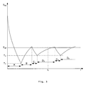
- FIG 3 shows the temperature T RA of the return air as a function of time t during the operation of the refrigeration system of the invention.
- the return air RA is drawn from the container, and the temperature T RA of the return air therefore represents the temperature of the cargo.
- a first phase A the cargo is refrigerated to a temperature T1 below the set-point temperature T SP .
- the compressor is operated at or near its full capacity to bring down the temperature of the cargo, and the evaporator fan is operated at low speed, the temperature T RA of the return air is monitored.
- Phase A is terminated when the temperature T RA of the return air reaches a first low temperature T 1 .
- phase B the compressor is inactivated and the evaporator fan is still operated at low speed to circulate air in the container.
- the temperature T RA of the return air will increase due to heat leakage from the ambient into the container and to the friction energy dissipated due to the air flow through the container.
- the temperature T RA of the return air is constantly monitored, and when the temperature of the return air reaches a predetermined upper limit temperature value related to the set-point temperature T SP , phase B is terminated. The duration of phase B is observed.
- phase C 1 the compressor and the evaporator fan are operated at the same conditions as in phase A, i.e. the compressor is operated at or near its full capacity, the evaporator fan is operated at low speed and the temperature T RA of the return air is monitored.
- Phase C 1 is terminated when the temperature T RA of the return air reaches a second low temperature T 2 which is higher than the first low temperature T 1 .
- phase D 1 the compressor is made inoperative and the evaporator fan is turned off. These two components thus consume no power, and the refrigeration system is in "sleep mode". When the evaporator fan is not operating there will be no air flow and thus no friction energy dissipated in the container, and the temperature curve in phase D 1 can therefore be expected to be less steep than in phase B. However, the starting temperature T 2 of phase D 1 is higher than the starting temperature T 1 of phase B. The target end temperature for phase D 1 is the same as for phase B. With the refrigeration system in "sleep mode" it will be necessary to determine a time for resuming refrigeration since there is no continuous monitoring of the return air temperature. In accordance with the invention this time is estimated based on the observed duration of a previous phase without refrigeration. As a first estimate, or seed estimate, the observed duration of phase B is taken.
- phase D 1 after the estimated duration of phase D 1 , which here is chosen equal to the observed duration of phase B, i.e. at the time t 1 , the evaporator fan is turned on for a period allowing measurement of the temperature T RA of the return air, thus ending the sleep mode for phase D 1 .
- the system enter a new sleep period (i.e., a period after the sleep mode for phase D 1 , in which the compressor and evaporator fan are again deactivated), and an estimated duration of the new sleep period is calculated by extrapolation of observed temperatures and durations.
- a new sleep period i.e., a period after the sleep mode for phase D 1 , in which the compressor and evaporator fan are again deactivated
- phase D 1 is terminated and phase C 2 is initiated where the system enters refrigeration mode with the compressor activated and evaporator fan operating at low speed.
- phase C 2 is similar to phase C 1 and the system is operated under the same conditions as in phase C 1 and phase C 2 is terminated when the temperature T RA of the return air reaches the second low temperature T 2 .
- the duration of the next sleep mode phase, phase D 2 is estimated based on the observed duration of the preceding sleep mode phase, phase D 1 , and the observed temperature at which it was terminated. In particular, if phase D1 was terminated at a temperature higher than the target end temperature, then the duration of phase D 2 , is estimated correspondingly shorter, and if phase D1 was terminated at a temperature lower than the target end temperature, then the duration of phase D 2 , is estimated correspondingly longer.
Abstract
Description
- This application claims the priority of
U.S. Provisional Patent Application No. 61/108,082, filed October 24, 2008 - This invention relates to climate control in cargo containers and to devices for controlling the climate in cargo containers. In particular the invention relates to refrigeration systems for use in cargo containers and methods for operating such systems.
- The present invention relates to transporting and storing temperature sensitive cargo over long periods of time using a controlled climate in the space where the cargo is loaded. Climate control includes controlling the temperature of the cargo within a certain acceptable range. Controlling the temperature includes bringing the temperature of the cargo into the acceptable range (by refrigerating or heating) and maintaining the temperature within that range. Climate control may also include controlling other parameters such as humidity and composition of the atmosphere.
- Refrigeration is the process of removing heat from an enclosed space, or from a substance, and moving it to a place where it is unobjectionable. The primary purpose of refrigeration is lowering the temperature of the enclosed space or substance and then maintaining that lower temperature.
- One commonly used refrigeration technique is the vapor-compression cycle. The vapor-compression cycle is used in most household refrigerators as well as in many large commercial and industrial refrigeration systems.
- A refrigerated container or reefer is a shipping container used in intermodal freight transport, including rail, ship and truck, where the cargo is refrigerated (chilled or frozen) for the transportation of temperature sensitive cargo. A reefer will usually have an integral refrigeration unit.
- The reliability of the refrigeration unit is of paramount importance. The temperature of temperature sensitive cargo should be kept within predefined limits. Some cargo must be maintained frozen, and the temperature of any part of the frozen cargo must be kept below a predefined freezing temperature which depends on the cargo, e.g. below -18 degrees C or lower, while other cargo, in particular commodities such as fresh meat, fresh fruit and vegetables, should be kept chilled to stay fresh, but not frozen. For chilled fruit and vegetables there is a lowest acceptable temperature below which the commodity will begin degrading and loose its freshness. Such temperature is dependent upon the type of fruit.
- In one embodiment, the invention provides a method for operating a refrigeration system for a container for refrigerating frozen cargo. The method includes providing a compressor, a condenser, and an evaporator connected in series, and providing an evaporator fan. The method also includes alternating operation of the compressor and the evaporator fan, in combination, between an active mode where the compressor compresses a refrigerant and directs the refrigerant through the condenser and the evaporator, and where the evaporator fan rotates to supply refrigerated supply air from the evaporator to the cargo within the container, and a sleep mode in which the compressor and the evaporator fan are deactivated, and operating the compressor and the evaporator fan in the sleep mode for a duration that is based on a measured duration of a prior sleep mode.
- Another embodiment of the invention provides a refrigeration system for a container for refrigerating frozen cargo. The system includes a compressor, a condenser, and an evaporator connected in series. The system also includes an evaporator fan and a controller. The controller is programmed to alternate operation of the compressor and the evaporator fan, in combination, between an active mode where the compressor compresses a refrigerant and directs the refrigerant through the condenser and the evaporator, and where the evaporator fan rotates to supply refrigerated supply air from the evaporator to the cargo within the container, and a sleep mode in which the compressor and the evaporator fan are deactivated. The controller is further programmed to operate the compressor and the evaporator fan in the sleep mode for a duration that is based on a measured duration of a prior sleep mode.
- Other aspects of the invention will become apparent by consideration of the detailed description and accompanying drawings.
-
Figure 1 shows schematically a refrigeration system according to the invention. -
Figure 2 shows a refrigerated container with the refrigeration system inFigure 1 installed. -
Figure 3 is a diagram illustrating the return air temperature when using the invention. - Before any embodiments of the invention are explained in detail, it is to be understood that the invention is not limited in its application to the details of construction and the arrangement of components set forth in the following description or illustrated in the following drawings. The invention is capable of other embodiments and of being practiced or of being carried out in various ways.
-
Figure 1 is a simplified diagram of the basic components of a typical one-stage vapor-compression refrigeration system 100 according to the invention. In this cycle, a circulating refrigerant enters thecompressor 110 as a vapor. In the compressor the vapor is compressed and exits the compressor superheated. The superheated vapor travels through thecondenser 120 which first cools and removes the superheat and then condenses the vapor into a liquid by removing additional heat at constant pressure and temperature. The liquid refrigerant goes through an expansion valve 130 (also called a throttle valve) where its pressure abruptly decreases, causing flash evaporation and auto-refrigeration of, typically, less than half of the liquid. That results in a mixture of liquid and vapor at a lower temperature and pressure. The cold liquid-vapor mixture then travels through theevaporator 140 coil or tubes and is completely vaporized by cooling the warm return air RA returning from the refrigerated space being blown by anevaporator fan 150 across the evaporator coil or tubes. The cool supply air SA is blown into the refrigerated space. The resulting refrigerant vapor returns to the compressor inlet to complete the thermodynamic cycle. Acondenser fan 160 removes condensation heat from thecondenser 120. Acontroller 170 controls the operation of the refrigeration system and its individual components. - During operation water vapor will condensate on the
evaporator 140 and form a layer of ice which will degrade the efficiency of the evaporator. The ice is removed in defrosting cycles where thecompressor 110 and theevaporator fan 150 are inactivated, and aheater 180 is activated which will heat theevaporator 140. Atemperature sensor 190 senses the temperature of theevaporator 140 and when it has been determined, based on the sensed evaporator temperature, that the ice is melted, thecompressor 110 is again activated. When the temperature of the evaporator is sufficiently low theevaporator fan 150 is activated and the refrigeration system operates again. - The
refrigeration system 100 can have one ormore evaporator fans 150. The power of the evaporator fan motors can be controlled in two or more steps or continuously by thecontroller 170. For simplicity, only high speed operation and low speed operation are described, but the person having ordinary skill in the art will understand that the described method applies in general to motors with controllable speed. -
Figure 2 shows schematically a portion of a refrigeratedcontainer 200 loaded withcargo 210 to be refrigerated, in this case the cargo is to be frozen and kept frozen. Thecontainer 200 has arefrigeration system 100 installed in one end, and the container has doors (not shown) in the opposite end for loading and unloading thecargo 210. The evaporator fan orfans 150 of therefrigeration system 100 blow refrigerated supply air SA into the container where it circulates around thecargo 210 and returns as return air RA to therefrigeration system 100. - The energy required for circulating the air in the container is ultimately dissipated as heat in the container due to friction. Depending on whether the
evaporator fan 150 is operated in a low speed mode or in a high speed mode it delivers from a few hundred watts or up to a few kilowatts (kW) which is dissipated as heat in the container. This energy adds to the energy that enters the container from the ambient and the heat that is generated by the cargo itself, all of which must be removed by the refrigeration system. Assuming efficiencies of 100 % of both the evaporator fan and the refrigeration system, for each kW consumed by the evaporator fan another kW will be consumed by the refrigeration system. -
Figure 3 shows the temperature TRA of the return air as a function of time t during the operation of the refrigeration system of the invention. The return air RA is drawn from the container, and the temperature TRA of the return air therefore represents the temperature of the cargo. - In a first phase A the cargo is refrigerated to a temperature T1 below the set-point temperature TSP. In this phase the compressor is operated at or near its full capacity to bring down the temperature of the cargo, and the evaporator fan is operated at low speed, the temperature TRA of the return air is monitored. Phase A is terminated when the temperature TRA of the return air reaches a first low temperature T1.
- In phase B the compressor is inactivated and the evaporator fan is still operated at low speed to circulate air in the container. In this phase the temperature TRA of the return air will increase due to heat leakage from the ambient into the container and to the friction energy dissipated due to the air flow through the container. The temperature TRA of the return air is constantly monitored, and when the temperature of the return air reaches a predetermined upper limit temperature value related to the set-point temperature TSP, phase B is terminated. The duration of phase B is observed.
- In phase C1 the compressor and the evaporator fan are operated at the same conditions as in phase A, i.e. the compressor is operated at or near its full capacity, the evaporator fan is operated at low speed and the temperature TRA of the return air is monitored. Phase C1 is terminated when the temperature TRA of the return air reaches a second low temperature T2 which is higher than the first low temperature T1.
- In phase D1 the compressor is made inoperative and the evaporator fan is turned off. These two components thus consume no power, and the refrigeration system is in "sleep mode". When the evaporator fan is not operating there will be no air flow and thus no friction energy dissipated in the container, and the temperature curve in phase D1 can therefore be expected to be less steep than in phase B. However, the starting temperature T2 of phase D1 is higher than the starting temperature T1 of phase B. The target end temperature for phase D1 is the same as for phase B. With the refrigeration system in "sleep mode" it will be necessary to determine a time for resuming refrigeration since there is no continuous monitoring of the return air temperature. In accordance with the invention this time is estimated based on the observed duration of a previous phase without refrigeration. As a first estimate, or seed estimate, the observed duration of phase B is taken.
- In phase D1, after the estimated duration of phase D1, which here is chosen equal to the observed duration of phase B, i.e. at the time t1, the evaporator fan is turned on for a period allowing measurement of the temperature TRA of the return air, thus ending the sleep mode for phase D1.
- If the observed temperature TRA of the return air is lower than a predetermined limit below the set-point temperature TSP the system enter a new sleep period (i.e., a period after the sleep mode for phase D1, in which the compressor and evaporator fan are again deactivated), and an estimated duration of the new sleep period is calculated by extrapolation of observed temperatures and durations.
- If the observed temperature TRA, of the return air is equal to or higher than the predetermined limit below the set-point temperature TSP phase D1 is terminated and phase C2 is initiated where the system enters refrigeration mode with the compressor activated and evaporator fan operating at low speed. In principle, phase C2 is similar to phase C1 and the system is operated under the same conditions as in phase C1 and phase C2 is terminated when the temperature TRA of the return air reaches the second low temperature T2.
- The duration of the next sleep mode phase, phase D2, is estimated based on the observed duration of the preceding sleep mode phase, phase D1, and the observed temperature at which it was terminated. In particular, if phase D1 was terminated at a temperature higher than the target end temperature, then the duration of phase D2, is estimated correspondingly shorter, and if phase D1 was terminated at a temperature lower than the target end temperature, then the duration of phase D2, is estimated correspondingly longer.
- Various features and advantages of the invention are set forth in the following claims.
Claims (15)
- A method for operating a refrigeration system for a container for refrigerating frozen cargo, the method comprising:providing a compressor, a condenser, and an evaporator connected in series;providing an evaporator fan;alternating operation of the compressor and the evaporator fan, in combination, between an active mode where the compressor compresses a refrigerant and directs the refrigerant through the condenser and the evaporator, and where the evaporator fan rotates to supply refrigerated supply air from the evaporator to the cargo within the container, and a sleep mode in which the compressor and the evaporator fan are deactivated;operating the compressor and the evaporator fan in the sleep mode for a duration that is based on a measured duration of a prior sleep mode.
- The method of claim 1, wherein the prior sleep mode is the preceding sleep mode; or
wherein operating the compressor and the evaporator fan in the sleep mode includes operating the compressor and the evaporator fan in the sleep mode for a duration that is based on a duration of a prior sleep mode and a measured return air temperature at which the prior sleep mode was terminated. - The method of claim 1, further comprising determining an initial duration of an initial sleep mode by the following steps in sequence:(i) operating the compressor and evaporator fan in the active mode;(ii) monitoring the temperature of return air from the container;(iii) deactivating the compressor when the temperature of the return air reaches a first predetermined low temperature which is lower than a predetermined set-point temperature;(iv) calculating the time difference between the moment when the return air reaches the first predetermined low temperature with the compressor and evaporator fan in the active mode and when the return air temperature reaches the predetermined set-point temperature after the compressor has been deactivated; andWherein the method may optionally further comprise activating the compressor and the evaporator fan in the active mode when the temperature of the return air reaches the predetermined set-point temperature.
- The method of claim 1, further comprising operating the compressor and evaporator fan in the active mode until the return air temperature reaches a first predetermined low temperature which is lower than the predetermined set-point temperature.
- The method of claim 4, further comprising operating the compressor and evaporator fan in the sleep mode after the return air temperature reaches the first predetermined low temperature and until expiration of a duration based on a preceding sleep mode.
- The method of claim 5, further comprising operating the evaporator fan upon expiration of the duration and measuring the return air temperature.
- The method of claim 6, further comprising operating the compressor and the evaporator fan in the active mode if the measured return air temperature is at or higher than the predetermined set-point temperature; and operating the compressor and the evaporator fan in a new sleep period for an estimated duration calculated by extrapolation of observed temperatures and durations if the measured return air is lower than the predetermined set-point temperature; or
further comprising shortening the duration of the next sleep mode when the measured return air temperature at which the last sleep mode was terminated was higher than the predetermined set-point temperature; or
further comprising extending the duration of the next sleep mode when the measured return air temperature at which the last sleep mode was terminated was lower than the predetermined set-point temperature. - A refrigeration system for a container for refrigerating frozen cargo, the system comprising:a compressor, a condenser, and an evaporator connected in series;an evaporator fan; anda controller programmed to alternate operation of the compressor and the evaporator fan, in combination, between an active mode where the compressor compresses a refrigerant and directs the refrigerant through the condenser and the evaporator, and where the evaporator fan rotates to supply refrigerated supply air from the evaporator to the cargo within the container, and a sleep mode in which the compressor and the evaporator fan are deactivated, andwherein the controller is programmed to operate the compressor and the evaporator fan in the sleep mode for a duration that is based on a measured duration of a prior sleep mode.
- The system of claim 6, wherein the prior sleep mode is the preceding sleep mode; or
wherein the controller is programmed to operate the compressor and the evaporator fan based on a measured return air temperature at which the prior sleep mode was terminated. - The system of claim 8, wherein a controller is programmed to determine an initial duration of an initial sleep mode by executing the following in sequence:(i) operating the compressor and the evaporator fan in the active mode;(ii) monitoring the temperature of return air from the container;(iii) deactivating the compressor when the temperature of the return air reaches a first predetermined low temperature which is lower than a predetermined set-point temperature;(iv) calculating the time difference between the moment when the return air reaches the first predetermined low temperature with the compressor and evaporator fan in the active mode and when the return air temperature reaches the predetermined set-point temperature after the compressor has been deactivated; andoptionally the controller may be programmed to activate the compressor and the evaporator fan in the active mode when the temperature of the return air reaches the predetermined set-point temperature.
- The system of claim 8, wherein the controller is programmed to operate the compressor and the evaporator fan in the active mode until the return air temperature reaches a first predetermined low temperature which is lower than the predetermined set-point temperature.
- The system of claim 11, wherein the controller is programmed to operate the compressor and the evaporator fan in the sleep mode after the return air temperature reaches the first predetermined low temperature and until expiration of a duration based on a preceding sleep mode.
- The system of claim 12, wherein the controller is programmed to operate the evaporator fan upon expiration of the duration and to measure the return air temperature.
- The system of claim 13, wherein the controller is programmed to operate the compressor and the evaporator fan in the active mode if the measured return air temperature is at or higher than the predetermined set-point temperature; and the controller is programmed to operate the compressor and the evaporator fan in a new sleep period for an estimated duration calculated by extrapolation of observed temperatures and durations if the measured return air temperature is lower than the predetermined set-point temperature; or
wherein the length of the duration of the next sleep mode is shortened when the measured return air temperature at which that last sleep mode was terminated was higher than the predetermined set-point temperature; or
wherein the length of the duration of the next sleep mode is extended when the measured return air temperature at which that last sleep mode was terminated was lower than the predetermined set-point temperature. - A method for operating a refrigeration system for a container for refrigerating frozen cargo, the method comprising:providing a compressor, a condenser, and an evaporator connected in series;providing an evaporator fan;alternating operation of the compressor and the evaporator fan, in combination, between an active mode where the compressor compresses a refrigerant and directs the refrigerant through the condenser and the evaporator, and where the evaporator fan rotates to supply refrigerated supply air from the evaporator to the cargo within the container, and a sleep mode in which the compressor and the evaporator fan are , deactivated;operating the compressor and the evaporator fan in the sleep mode for a duration that is based on a measured duration of a prior sleep mode;operating the compressor and evaporator fan in the active mode until the return air temperature reaches a first predetermined low temperature which is lower than the predetermined set-point temperature;operating the compressor and evaporator fan in the sleep mode after the return air temperature reaches the first predetermined low temperature and until expiration of a duration based on a preceding sleep mode;operating the evaporator fan upon expiration of the duration based on the preceding sleep mode and measuring a return air temperature;operating the compressor and the evaporator fan in the active mode if the measured return air temperature is at or higher than the predetermined set-point temperature; and operating the compressor and the evaporator fan in a new sleep period for an estimated duration calculated by extrapolation of observed temperatures and durations if the measured return air is lower than the predetermined set-point temperature;shortening the duration of the next sleep mode when the measured return air temperature at which the last sleep mode was terminated was higher than the predetermined set-point temperature; andextending the duration of the next sleep mode when the measured return air temperature at which the last sleep mode was terminated was lower than the predetermined set-point temperature.
Applications Claiming Priority (1)
| Application Number | Priority Date | Filing Date | Title |
|---|---|---|---|
| US10808208P | 2008-10-24 | 2008-10-24 |
Publications (2)
| Publication Number | Publication Date |
|---|---|
| EP2180279A2 true EP2180279A2 (en) | 2010-04-28 |
| EP2180279A3 EP2180279A3 (en) | 2013-02-27 |
Family
ID=41630883
Family Applications (1)
| Application Number | Title | Priority Date | Filing Date |
|---|---|---|---|
| EP09252464A Withdrawn EP2180279A3 (en) | 2008-10-24 | 2009-10-22 | Controlling frozen state of a cargo |
Country Status (3)
| Country | Link |
|---|---|
| US (1) | US20100106302A1 (en) |
| EP (1) | EP2180279A3 (en) |
| JP (1) | JP5483995B2 (en) |
Cited By (3)
| Publication number | Priority date | Publication date | Assignee | Title |
|---|---|---|---|---|
| EP2535672A3 (en) * | 2011-06-16 | 2013-05-22 | A.P. Møller - Mærsk A/S | Internal air circulation control in a refrigerated transport container |
| US20140311171A1 (en) * | 2008-10-24 | 2014-10-23 | Thermo King Corporation | Controlling chilled state of a cargo |
| EP2831513A4 (en) * | 2012-03-29 | 2016-01-13 | Nest Labs Inc | Enclosure cooling using early compressor turn-off with extended fan operation |
Families Citing this family (7)
| Publication number | Priority date | Publication date | Assignee | Title |
|---|---|---|---|---|
| US8776796B2 (en) * | 2011-12-09 | 2014-07-15 | Colabs, Inc. | Apparatus and method for improved assisted ventilation |
| JP5984784B2 (en) * | 2013-11-19 | 2016-09-06 | 三菱電機株式会社 | Hot / cold water air conditioning system |
| US10254027B2 (en) * | 2014-05-02 | 2019-04-09 | Thermo King Corporation | Method and system for controlling operation of evaporator fans in a transport refrigeration system |
| US10247460B2 (en) * | 2014-05-15 | 2019-04-02 | Lennox Industries Inc. | Accommodating CSSH for tandem compressor transitions |
| US10703174B2 (en) * | 2015-11-30 | 2020-07-07 | Thermo King Corporation | Device and method for controlling operation of transport refrigeration unit |
| JP6788008B2 (en) * | 2016-07-06 | 2020-11-18 | 三菱電機株式会社 | Refrigeration cycle equipment |
| WO2018178405A1 (en) | 2017-03-28 | 2018-10-04 | Universitat De Lleida | Adaptive control method for refrigeration systems |
Family Cites Families (49)
| Publication number | Priority date | Publication date | Assignee | Title |
|---|---|---|---|---|
| US4292813A (en) * | 1979-03-08 | 1981-10-06 | Whirlpool Corporation | Adaptive temperature control system |
| US4663725A (en) * | 1985-02-15 | 1987-05-05 | Thermo King Corporation | Microprocessor based control system and method providing better performance and better operation of a shipping container refrigeration system |
| US4725001A (en) * | 1986-10-17 | 1988-02-16 | Arnold D. Berkeley | Electronic thermostat employing adaptive cycling |
| US4790143A (en) * | 1987-10-23 | 1988-12-13 | Thermo King Corporation | Method and apparatus for monitoring a transport refrigeration system and its conditioned load |
| US4787214A (en) * | 1987-11-23 | 1988-11-29 | Thermo King Corporation | Transport refrigeration system |
| US4899549A (en) * | 1989-01-31 | 1990-02-13 | Thermo King Corporation | Transport refrigeration system with improved temperature and humidity control |
| US4850198A (en) * | 1989-01-17 | 1989-07-25 | American Standard Inc. | Time based cooling below set point temperature |
| US4949550A (en) * | 1989-10-04 | 1990-08-21 | Thermo King Corporation | Method and apparatus for monitoring a transport refrigeration system and its conditioned load |
| US4977752A (en) * | 1989-12-28 | 1990-12-18 | Thermo King Corporation | Transport refrigeration including methods and apparatus for optmizing same |
| US5295364A (en) * | 1991-01-15 | 1994-03-22 | Thermo King Corporation | Refrigeration pull-down technique |
| US5201185A (en) * | 1991-07-11 | 1993-04-13 | Thermo King Corporation | Method of operating a transport refrigeration unit |
| US5140826A (en) * | 1991-07-11 | 1992-08-25 | Thermo King Corporation | Method of operating a transport refrigeration unit |
| US5123253A (en) * | 1991-07-11 | 1992-06-23 | Thermo King Corporation | Method of operating a transport refrigeration unit |
| US5201186A (en) * | 1991-07-11 | 1993-04-13 | Thermo King Corporation | Method of operating a transport refrigeration unit |
| US5222368A (en) * | 1991-07-11 | 1993-06-29 | Thermo King Corporation | Method of operating a transport refigeration unit |
| US5123252A (en) * | 1991-07-11 | 1992-06-23 | Thermo King Corporation | Method of operating a transport refrigeration unit |
| US5140825A (en) * | 1991-07-11 | 1992-08-25 | Thermo King Corporation | Method of operating a transport refrigeration unit |
| US5123251A (en) * | 1991-07-11 | 1992-06-23 | Thermo King Corporation | Method of operating a transport refrigeration unit |
| US5161383A (en) * | 1991-07-11 | 1992-11-10 | Thermo King Corporation | Method of operating a transport refrigeration unit |
| US5197670A (en) * | 1991-10-24 | 1993-03-30 | Thermo King Corporation | Method of operating a transport refrigeration unit |
| US5161384A (en) * | 1992-02-10 | 1992-11-10 | Thermo King Corporation | Method of operating a transport refrigeration system |
| US5186015A (en) * | 1992-02-27 | 1993-02-16 | Thermo King Corporation | Transport refrigeration unit and method of operating same |
| US5168713A (en) * | 1992-03-12 | 1992-12-08 | Thermo King Corporation | Method of operating a compartmentalized transport refrigeration system |
| US5181389A (en) * | 1992-04-26 | 1993-01-26 | Thermo King Corporation | Methods and apparatus for monitoring the operation of a transport refrigeration system |
| US5228301A (en) * | 1992-07-27 | 1993-07-20 | Thermo King Corporation | Methods and apparatus for operating a refrigeration system |
| JPH06109352A (en) * | 1992-09-25 | 1994-04-19 | Mitsubishi Heavy Ind Ltd | Refrigeration apparatus for container |
| US5249429A (en) * | 1993-02-08 | 1993-10-05 | Thermo King Corporation | Methods of operating a refrigeration system |
| US5303560A (en) * | 1993-04-15 | 1994-04-19 | Thermo King Corporation | Method and apparatus for monitoring and controlling the operation of a refrigeration unit |
| JPH0812030B2 (en) * | 1993-06-08 | 1996-02-07 | 中野冷機株式会社 | How to drive the showcase |
| US5456088A (en) * | 1993-11-12 | 1995-10-10 | Thermo King Corporation | Refrigeration unit and method of operating same |
| JPH07270027A (en) * | 1994-03-29 | 1995-10-20 | Toshiba Corp | Deep freezing controller for refrigerator |
| US5557938A (en) * | 1995-02-27 | 1996-09-24 | Thermo King Corporation | Transport refrigeration unit and method of operating same |
| US5579648A (en) * | 1995-04-19 | 1996-12-03 | Thermo King Corporation | Method of monitoring a transport refrigeration unit and an associated conditioned load |
| US5572879A (en) * | 1995-05-25 | 1996-11-12 | Thermo King Corporation | Methods of operating a refrigeration unit in predetermined high and low ambient temperatures |
| US5596878A (en) * | 1995-06-26 | 1997-01-28 | Thermo King Corporation | Methods and apparatus for operating a refrigeration unit |
| US5634347A (en) * | 1996-04-10 | 1997-06-03 | Thermo King Corporation | Method of controlling a transport refrigeration system without refrigerant modulation |
| DE19736818A1 (en) * | 1997-08-23 | 1999-02-25 | Behr Gmbh & Co | Method and device for evaporator icing-protected air conditioning control |
| US6095427A (en) * | 1999-04-22 | 2000-08-01 | Thermo King Corporation | Temperature control system and method for efficiently obtaining and maintaining the temperature in a conditioned space |
| JP4229555B2 (en) * | 1999-12-17 | 2009-02-25 | 福島工業株式会社 | Storage room with temperature control function |
| US6862499B1 (en) * | 2000-07-14 | 2005-03-01 | Thermo King Corporation | Environment-controlled transport unit |
| US6679074B2 (en) * | 2001-07-31 | 2004-01-20 | Thermo King Corporation | Automatic switching refrigeration system |
| US6708510B2 (en) * | 2001-08-10 | 2004-03-23 | Thermo King Corporation | Advanced refrigeration system |
| JP2003083658A (en) * | 2001-09-10 | 2003-03-19 | Sanyo Electric Co Ltd | Cooling storage cabinet |
| US6829523B2 (en) * | 2002-02-26 | 2004-12-07 | Thermo King Corporation | Method and apparatus for controlling a transport temperature control unit having selectively programmable temperature ranges |
| US6895764B2 (en) * | 2003-05-02 | 2005-05-24 | Thermo King Corporation | Environmentally friendly method and apparatus for cooling a temperature controlled space |
| US6910341B2 (en) * | 2003-09-26 | 2005-06-28 | Thermo King Corporation | Temperature control apparatus and method of operating the same |
| KR100569891B1 (en) * | 2003-12-18 | 2006-04-10 | 엘지전자 주식회사 | Method for control operation of pan in refrigerator |
| US7080521B2 (en) * | 2004-08-31 | 2006-07-25 | Thermo King Corporation | Mobile refrigeration system and control |
| US8136363B2 (en) * | 2005-04-15 | 2012-03-20 | Thermo King Corporation | Temperature control system and method of operating the same |
-
2009
- 2009-10-22 EP EP09252464A patent/EP2180279A3/en not_active Withdrawn
- 2009-10-22 US US12/604,022 patent/US20100106302A1/en not_active Abandoned
- 2009-10-23 JP JP2009244384A patent/JP5483995B2/en active Active
Non-Patent Citations (1)
| Title |
|---|
| None |
Cited By (7)
| Publication number | Priority date | Publication date | Assignee | Title |
|---|---|---|---|---|
| US20140311171A1 (en) * | 2008-10-24 | 2014-10-23 | Thermo King Corporation | Controlling chilled state of a cargo |
| US9857114B2 (en) * | 2008-10-24 | 2018-01-02 | Thermo King Corporation | Controlling chilled state of a cargo |
| US10619902B2 (en) | 2008-10-24 | 2020-04-14 | Thermo King Corporation | Controlling chilled state of a cargo |
| EP2535672A3 (en) * | 2011-06-16 | 2013-05-22 | A.P. Møller - Mærsk A/S | Internal air circulation control in a refrigerated transport container |
| EP2831513A4 (en) * | 2012-03-29 | 2016-01-13 | Nest Labs Inc | Enclosure cooling using early compressor turn-off with extended fan operation |
| US9534805B2 (en) | 2012-03-29 | 2017-01-03 | Google Inc. | Enclosure cooling using early compressor turn-off with extended fan operation |
| EP3734181A1 (en) * | 2012-03-29 | 2020-11-04 | Google LLC | Enclosure cooling using early compressor turn-off with extended fan operation |
Also Published As
| Publication number | Publication date |
|---|---|
| JP5483995B2 (en) | 2014-05-07 |
| JP2010101618A (en) | 2010-05-06 |
| US20100106302A1 (en) | 2010-04-29 |
| EP2180279A3 (en) | 2013-02-27 |
Similar Documents
| Publication | Publication Date | Title |
|---|---|---|
| US10619902B2 (en) | Controlling chilled state of a cargo | |
| EP2180279A2 (en) | Controlling frozen state of a cargo | |
| EP2180278B1 (en) | Control of pull-down in refrigeration systems | |
| EP2588819B1 (en) | Evaporator refrigerant saturation demand defrost | |
| CN101918775B (en) | Control method of refrigerator | |
| US9557084B2 (en) | Apparatus for controlling relative humidity in a container | |
| JPH029269B2 (en) | ||
| NL2009581C2 (en) | A method for operating a refrigeration system for a cargo container. | |
| KR20110086345A (en) | A method for controlling a refrigerator with two evaporators | |
| KR20150111408A (en) | Method for controlling refrigerators keeping temperature while defrosting operation | |
| JPH04194564A (en) | Refrigerator | |
| WO2018067095A2 (en) | Refrigeration appliance with zero degree compartment having improved temperature control | |
| JPH0444179B2 (en) |
Legal Events
| Date | Code | Title | Description |
|---|---|---|---|
| PUAI | Public reference made under article 153(3) epc to a published international application that has entered the european phase |
Free format text: ORIGINAL CODE: 0009012 |
|
| AK | Designated contracting states |
Kind code of ref document: A2 Designated state(s): AT BE BG CH CY CZ DE DK EE ES FI FR GB GR HR HU IE IS IT LI LT LU LV MC MK MT NL NO PL PT RO SE SI SK SM TR |
|
| AX | Request for extension of the european patent |
Extension state: AL BA RS |
|
| RAP1 | Party data changed (applicant data changed or rights of an application transferred) |
Owner name: JOHNSON CONTROLS TECHNOLOGY COMPANY |
|
| RAP1 | Party data changed (applicant data changed or rights of an application transferred) |
Owner name: JOHNSON CONTROLS TECHNOLOGY COMPANY Owner name: THERMO KING CORPORATION |
|
| PUAL | Search report despatched |
Free format text: ORIGINAL CODE: 0009013 |
|
| AK | Designated contracting states |
Kind code of ref document: A3 Designated state(s): AT BE BG CH CY CZ DE DK EE ES FI FR GB GR HR HU IE IS IT LI LT LU LV MC MK MT NL NO PL PT RO SE SI SK SM TR |
|
| AX | Request for extension of the european patent |
Extension state: AL BA RS |
|
| RIC1 | Information provided on ipc code assigned before grant |
Ipc: F25D 29/00 20060101AFI20130122BHEP |
|
| STAA | Information on the status of an ep patent application or granted ep patent |
Free format text: STATUS: THE APPLICATION IS DEEMED TO BE WITHDRAWN |
|
| 18D | Application deemed to be withdrawn |
Effective date: 20130828 |