EP2180261A2 - Hydraulic connection for combined heat and power plants - Google Patents
Hydraulic connection for combined heat and power plants Download PDFInfo
- Publication number
- EP2180261A2 EP2180261A2 EP09012955A EP09012955A EP2180261A2 EP 2180261 A2 EP2180261 A2 EP 2180261A2 EP 09012955 A EP09012955 A EP 09012955A EP 09012955 A EP09012955 A EP 09012955A EP 2180261 A2 EP2180261 A2 EP 2180261A2
- Authority
- EP
- European Patent Office
- Prior art keywords
- coolant
- combined heat
- arrangement
- power plant
- heat
- Prior art date
- Legal status (The legal status is an assumption and is not a legal conclusion. Google has not performed a legal analysis and makes no representation as to the accuracy of the status listed.)
- Withdrawn
Links
- 239000002826 coolant Substances 0.000 claims abstract description 39
- 238000010438 heat treatment Methods 0.000 claims abstract description 31
- 238000001816 cooling Methods 0.000 claims abstract description 7
- 239000008236 heating water Substances 0.000 claims description 13
- 238000000605 extraction Methods 0.000 claims description 3
- 238000002156 mixing Methods 0.000 claims description 2
- 238000010248 power generation Methods 0.000 abstract description 2
- 239000002918 waste heat Substances 0.000 description 5
- 239000000498 cooling water Substances 0.000 description 4
- 239000000446 fuel Substances 0.000 description 4
- 238000002485 combustion reaction Methods 0.000 description 3
- 230000010354 integration Effects 0.000 description 3
- 238000000034 method Methods 0.000 description 3
- XLYOFNOQVPJJNP-UHFFFAOYSA-N water Substances O XLYOFNOQVPJJNP-UHFFFAOYSA-N 0.000 description 3
- 238000006243 chemical reaction Methods 0.000 description 2
- 238000009833 condensation Methods 0.000 description 2
- 230000005494 condensation Effects 0.000 description 2
- 230000001419 dependent effect Effects 0.000 description 2
- 230000005611 electricity Effects 0.000 description 2
- 238000011049 filling Methods 0.000 description 2
- 239000007789 gas Substances 0.000 description 2
- 238000009434 installation Methods 0.000 description 2
- 238000005260 corrosion Methods 0.000 description 1
- 230000007797 corrosion Effects 0.000 description 1
- 230000002349 favourable effect Effects 0.000 description 1
- 238000012423 maintenance Methods 0.000 description 1
- 239000010705 motor oil Substances 0.000 description 1
- 238000005457 optimization Methods 0.000 description 1
- 230000008092 positive effect Effects 0.000 description 1
- 230000001105 regulatory effect Effects 0.000 description 1
- 239000000126 substance Substances 0.000 description 1
- 238000011144 upstream manufacturing Methods 0.000 description 1
- 238000013022 venting Methods 0.000 description 1
Images
Classifications
-
- F—MECHANICAL ENGINEERING; LIGHTING; HEATING; WEAPONS; BLASTING
- F24—HEATING; RANGES; VENTILATING
- F24D—DOMESTIC- OR SPACE-HEATING SYSTEMS, e.g. CENTRAL HEATING SYSTEMS; DOMESTIC HOT-WATER SUPPLY SYSTEMS; ELEMENTS OR COMPONENTS THEREFOR
- F24D11/00—Central heating systems using heat accumulated in storage masses
- F24D11/002—Central heating systems using heat accumulated in storage masses water heating system
-
- F—MECHANICAL ENGINEERING; LIGHTING; HEATING; WEAPONS; BLASTING
- F24—HEATING; RANGES; VENTILATING
- F24D—DOMESTIC- OR SPACE-HEATING SYSTEMS, e.g. CENTRAL HEATING SYSTEMS; DOMESTIC HOT-WATER SUPPLY SYSTEMS; ELEMENTS OR COMPONENTS THEREFOR
- F24D18/00—Small-scale combined heat and power [CHP] generation systems specially adapted for domestic heating, space heating or domestic hot-water supply
-
- F—MECHANICAL ENGINEERING; LIGHTING; HEATING; WEAPONS; BLASTING
- F24—HEATING; RANGES; VENTILATING
- F24D—DOMESTIC- OR SPACE-HEATING SYSTEMS, e.g. CENTRAL HEATING SYSTEMS; DOMESTIC HOT-WATER SUPPLY SYSTEMS; ELEMENTS OR COMPONENTS THEREFOR
- F24D3/00—Hot-water central heating systems
- F24D3/10—Feed-line arrangements, e.g. providing for heat-accumulator tanks, expansion tanks ; Hydraulic components of a central heating system
-
- F—MECHANICAL ENGINEERING; LIGHTING; HEATING; WEAPONS; BLASTING
- F24—HEATING; RANGES; VENTILATING
- F24H—FLUID HEATERS, e.g. WATER OR AIR HEATERS, HAVING HEAT-GENERATING MEANS, e.g. HEAT PUMPS, IN GENERAL
- F24H9/00—Details
- F24H9/12—Arrangements for connecting heaters to circulation pipes
-
- F—MECHANICAL ENGINEERING; LIGHTING; HEATING; WEAPONS; BLASTING
- F24—HEATING; RANGES; VENTILATING
- F24D—DOMESTIC- OR SPACE-HEATING SYSTEMS, e.g. CENTRAL HEATING SYSTEMS; DOMESTIC HOT-WATER SUPPLY SYSTEMS; ELEMENTS OR COMPONENTS THEREFOR
- F24D2101/00—Electric generators of small-scale CHP systems
- F24D2101/70—Electric generators driven by internal combustion engines [ICE]
-
- F—MECHANICAL ENGINEERING; LIGHTING; HEATING; WEAPONS; BLASTING
- F24—HEATING; RANGES; VENTILATING
- F24D—DOMESTIC- OR SPACE-HEATING SYSTEMS, e.g. CENTRAL HEATING SYSTEMS; DOMESTIC HOT-WATER SUPPLY SYSTEMS; ELEMENTS OR COMPONENTS THEREFOR
- F24D2103/00—Thermal aspects of small-scale CHP systems
- F24D2103/10—Small-scale CHP systems characterised by their heat recovery units
- F24D2103/17—Storage tanks
-
- F—MECHANICAL ENGINEERING; LIGHTING; HEATING; WEAPONS; BLASTING
- F24—HEATING; RANGES; VENTILATING
- F24D—DOMESTIC- OR SPACE-HEATING SYSTEMS, e.g. CENTRAL HEATING SYSTEMS; DOMESTIC HOT-WATER SUPPLY SYSTEMS; ELEMENTS OR COMPONENTS THEREFOR
- F24D2103/00—Thermal aspects of small-scale CHP systems
- F24D2103/20—Additional heat sources for supporting thermal peak loads
-
- Y—GENERAL TAGGING OF NEW TECHNOLOGICAL DEVELOPMENTS; GENERAL TAGGING OF CROSS-SECTIONAL TECHNOLOGIES SPANNING OVER SEVERAL SECTIONS OF THE IPC; TECHNICAL SUBJECTS COVERED BY FORMER USPC CROSS-REFERENCE ART COLLECTIONS [XRACs] AND DIGESTS
- Y02—TECHNOLOGIES OR APPLICATIONS FOR MITIGATION OR ADAPTATION AGAINST CLIMATE CHANGE
- Y02E—REDUCTION OF GREENHOUSE GAS [GHG] EMISSIONS, RELATED TO ENERGY GENERATION, TRANSMISSION OR DISTRIBUTION
- Y02E20/00—Combustion technologies with mitigation potential
- Y02E20/14—Combined heat and power generation [CHP]
Definitions
- the invention relates to an arrangement for the hydraulic connection of a combined heat and power plant (CHP), in particular a micro-combined heat and power plant (micro CHP), in a heating system.
- CHP combined heat and power plant
- micro CHP micro-combined heat and power plant
- a combined heat and power plant converts the chemical energy of a fuel into electricity and heat.
- micro-CHP systems are used in single-family homes, residential buildings, smaller commercial enterprises and hotels.
- Such micro CHP plants use, for example, fuel cells or internal combustion engines with internal or external combustion for the generation of electrical energy.
- the DE 201 03 062 relates to a distribution station for heating and water supply systems.
- the possibility of connecting a cogeneration unit and a constant control or compliance with the return temperature of the coolant with an external hydraulic connection box is not described.
- the DE 195 35 752 describes a building energy management system using a cogeneration unit, where the essential components of this system should be located locally together to avoid heat loss. However, a common arrangement of the components does not provide the CHP system with a constant, controllable return temperature of the coolant.
- the invention has for its object to provide an arrangement for the hydraulic connection of a combined heat and power plant, in particular a micro-combined heat and power plant with a building heating system available that can be used universally.
- the inventive arrangement supports the use of certain energy conversion techniques in the micro CHP plant, in which the hydraulic interface of the micro CHP plant provides a constant return temperature of the coolant and / or promotes the coolant.
- the hydraulic interface also ensures that the maximum volume flow of the coolant is not exceeded and a constant temperature difference between the flow and return of the micro CHP plant is set.
- the coolant of the micro-CHP system is led to the outside, so that the heat is delivered to the heating circuit or to the hydraulic system of the building in the hydraulic interface.
- this waste heat can be used in particular for heating purposes and for process and domestic water heating.
- the hydraulic interface assumes control tasks, such as providing a return temperature of the coolant of the CHP unit to an adjustable but constant level.
- control tasks such as providing a return temperature of the coolant of the CHP unit to an adjustable but constant level.
- a regulation is outside the actual CHP unit and the control module allows the connection of other hydraulic supply lines of the building.
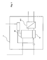
- FIG. 1 schematically shows a micro CHP plant 1 - eg a block heating plant (CHP) - according to the prior art.
- a gas combustion engine M drives a generator G for power generation. This converts the mechanical energy of the motor M into electrical energy.
- the resulting waste heat from the cooling water, the exhaust gas of the drive motor or the waste heat of the generator is decoupled via a plurality of heat exchangers.
- FIG. 1 shown plate heat exchanger WT used for heating and water heating.
- the block heating plant is connected directly to the local power grid.
- the generated electricity can be either used or fed.
- the use of a block heating plant is either as a sole heat generator or in conjunction with a boiler for peak load coverage. In both cases, a buffer storage contributes significantly to the optimization of the block heater capacity.
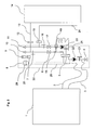
- FIG. 2 schematically shows the hydraulic interface 30 according to the invention, arranged between a coolant flow 2 and a coolant return 3 of the micro CHP plant 1 and a heating water buffer storage 14 of a heating system.
- hydraulic components such as a Schunikpumpe 20, a coolant pump 22 and a heat exchanger 5 are arranged, which are necessary for the heat extraction from the micro-CHP plant 1 in the heating system.
- the heating circuit pump 20 draws in cold heating water from the heating water buffer memory 14 via a return line 24. Depending on the operating status of the heating system, this heating water can assume temperatures between 5 ° C and 90 ° C.
- the heating water from the return of the buffer storage warm heating water from the coolant flow 2 of the heat exchanger 5 is mixed according to the position of a three-way mixing valve 18.
- the degree of admixing is dependent on the heating water temperature downstream of the heating circuit 20. This temperature is chosen so that sets a corresponding temperature at the outlet of the heat exchanger in the return of the coolant at corresponding flow rates of the heating water and the coolant.
- the electrical connections (9, 25) of the CHP installation are also accommodated there, which are required for the electrical integration of the micro CHP system into the electrical domestic network or into the public power grid.
- the return temperature of the coolant should be kept constant and above the target engine oil temperature in order to avoid condensation phenomena. Corrosion caused by this condensation should be avoided.
- the temperature of the engine cylinder head is measured in the inventive arrangement via a temperature sensor 26 and may be between 65 ° C and 90 ° C.
- a temperature sensor 23 the return temperature is monitored from the cogeneration unit 1 at start and when reaching a target temperature of 65 ° C, the sensor 23 acts as a switch-on for the pump running.
- the return temperature from the buffer memory 14 is monitored via the temperature sensor 16, where temperatures of 5 ° C to 90 ° C are measured.
- the temperature is selected such that, given corresponding volume flows of the heating water and of the coolant, a defined temperature at the outlet of the heat exchanger in the return of the coolant of e.g. 65 ° C.
- the life of the motor M is favored. Particularly advantageous is a temperature difference at which a flow target temperature of 80 ° C is not exceeded.
- a constant return temperature in the cooling water circuit also has a positive effect on the service life of the engine when a liquid-cooled fuel cell system is used. It is known that in high-temperature PEM fuel cell systems, small temperature differences between coolant supply and return are desirable from a life-time point of view.
- the cooling water circuit of the micro CHP plant 1 can be filled and vented via the hydraulic interface 30, in which the coolant is filled or vented into a surge tank 29 via a filling or venting hose 27, 28.
- the compensating vessel 29 has a closure lid 8 with a pressure valve for regulating the resulting overpressure and underpressure.
- the cooling water circuit can be emptied via a drain valve 4 in the hydraulic interface 30. This simplifies the filling and emptying of micro CHP plants. As such, the micro CHP system no longer needs to be opened for this purpose.
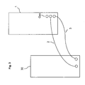
- Fig. 3 schematically shows the connection of the hydraulic interface 30 and the micro-CHP plant 1.
- the hydraulic interface 30 is easier to install, because all hydraulic facilities for the integration of the micro CHP plant 1 are concentrated there. Integration errors, caused for example by a wrongly placed pump or a valve, can thus be largely avoided.
- the hydraulic interface 30 basically allows the connection of different micro-CHP systems via the same defined interface to the heating system.
- the coolant from the micro-CHP system is routed outside and directed into the hydraulic interface so that the heat is released to the heating circuit or to the hydraulic system of the building.
- the hydraulic interface allows easy adjustment and regulation of a constant return temperature of the coolant circuit of the micro CHP plant.
- the setting of constant temperature differences in the coolant circuit is also possible via the hydraulic interface.
- the inventive arrangement is the simple and error-free installation necessary for the operation of micro-CHP plants hydraulic and electrical components and their easier maintenance ensured.
Landscapes
- Engineering & Computer Science (AREA)
- Physics & Mathematics (AREA)
- Thermal Sciences (AREA)
- Chemical & Material Sciences (AREA)
- Combustion & Propulsion (AREA)
- Mechanical Engineering (AREA)
- General Engineering & Computer Science (AREA)
- Heat-Pump Type And Storage Water Heaters (AREA)
- Central Heating Systems (AREA)
Abstract
Description
Die Erfindung bezieht sich auf eine Anordnung zur hydraulischen Anbindung einer Kraft-Wärme-Kopplungsanlage (KWK), insbesondere einer Mikro-Kraft-Wärme-Kopplungsanlage (Mikro-KWK), in ein Heizungssystem.The invention relates to an arrangement for the hydraulic connection of a combined heat and power plant (CHP), in particular a micro-combined heat and power plant (micro CHP), in a heating system.
Eine mit Kraft-Wärme-Kopplung betriebene Energiewandlungsanlage wandelt die chemische Energie eines Brennstoffs in Strom und Wärme um. Zunehmend finden so genannte Mikro-KWK-Anlagen Einsatz in Einfamilienhäusern, Wohngebäuden, kleineren Gewerbebetrieben und Hotels. Solche Mikro-KWK-Anlagen verwenden beispielsweise Brennstoffzellen oder Verbrennungskraftmaschinen mit interner oder externer Verbrennung für die Erzeugung der elektrischen Energie.A combined heat and power plant converts the chemical energy of a fuel into electricity and heat. Increasingly, so-called micro-CHP systems are used in single-family homes, residential buildings, smaller commercial enterprises and hotels. Such micro CHP plants use, for example, fuel cells or internal combustion engines with internal or external combustion for the generation of electrical energy.
In der
In der Druckschrift
Die
Die
Der Erfindung liegt die Aufgabe zugrunde, eine Anordnung zur hydraulischen Anbindung einer Kraft-Wärme-Kopplungsanlage, insbesondere einer Mikro-Kraft-Wärme-Kopplungsanlage mit einem Gebäudeheizungssystem zur Verfügung zu stellen, die universell einsetzbar ist.The invention has for its object to provide an arrangement for the hydraulic connection of a combined heat and power plant, in particular a micro-combined heat and power plant with a building heating system available that can be used universally.
Erfindungsgemäß wird dies gemäß den Merkmalen des Anspruchs 1 dadurch erreicht, dass die Anordnung zur Anbindung einer Kraft-Wärme-Kopplungsanlage, insbesondere einer Mikro-Kraft-Wärme-Kopplungsanlage, mit einem Kühlkreislauf bestehend aus einem Kühlmittelvorlauf und einem Kühlmittelrücklauf, in einem Gebäudeheizungssystem mit einem Speicher aus einer hydraulischen Schnittstelle, angeordnet zwischen dem Kühlkreislauf der Kraft-Wärme-Kopplungsanlage und dem Speicher des Heizungssystems, besteht.This is achieved according to the features of
Mit der erfindungsgemäßen Anordnung können verschiedene Energiewandlungstechniken in der Mikro-KWK-Anlage Verwendung finden, ohne dass diese Anordnung - die als externe hydraulische Schnittstelle zwischen dem internen Kühlkreislauf der Mikro-KWK-Anlage und dem Heizungssystem fungiert - entscheidend verändert werden muss.With the arrangement according to the invention, various energy conversion techniques in micro CHP plant without having to make any significant changes to this arrangement - which acts as an external hydraulic interface between the internal cooling circuit of the micro CHP plant and the heating system.
Des Weiteren wird durch die erfindungsgemäße Anordnung der Einsatz bestimmter Energiewandlungstechniken in der Mikro-KWK-Anlage unterstützt, in dem die hydraulische Schnittstelle der Mikro-KWK-Anlage eine konstante Rücklauftemperatur des Kühlmittels bereitstellt und/oder das Kühlmittel fördert. Die hydraulische Schnittstelle stellt auch sicher, dass der maximale Volumenstrom des Kühlmittels nicht überschritten und eine konstante Temperaturdifferenz zwischen Vor- und Rücklauf der Mikro-KWK-Anlage eingestellt wird.Furthermore, the inventive arrangement supports the use of certain energy conversion techniques in the micro CHP plant, in which the hydraulic interface of the micro CHP plant provides a constant return temperature of the coolant and / or promotes the coolant. The hydraulic interface also ensures that the maximum volume flow of the coolant is not exceeded and a constant temperature difference between the flow and return of the micro CHP plant is set.
Vorteilhafte Ausgestaltungen ergeben sich durch die Merkmale der abhängigen Ansprüche.Advantageous embodiments result from the features of the dependent claims.
Bei der erfindungsgemäßen Anordnung wird das Kühlmittel des Mikro-KWK-Systems nach außen geführt, so dass die Wärme an den Heizkreis oder an das hydraulische System des Gebäudes in der hydraulischen Schnittstelle abgegeben wird. Mit der Wärmeauskopplung der Abwärme des Energiewandlers aus der Mikro-KWK-Anlage und deren Übertragung auf das Heizungssystem des Gebäudes kann diese Abwärme insbesondere für Heizzwecke sowie für Prozess- und die Brauchwassererwärmung genutzt werden.In the arrangement according to the invention, the coolant of the micro-CHP system is led to the outside, so that the heat is delivered to the heating circuit or to the hydraulic system of the building in the hydraulic interface. With the heat extraction of the waste heat of the energy converter from the micro-CHP plant and their transfer to the heating system of the building, this waste heat can be used in particular for heating purposes and for process and domestic water heating.
Die hydraulische Schnittstelle übernimmt regelungstechnische Aufgaben, wie z.B. das Bereitstellen einer Rücklauftemperatur des Kühlmittels der KWK-Einheit auf ein einstellbares, aber konstantes Niveau. Somit befindet sich eine solche Regelung außerhalb der eigentlichen KWK-Einheit und das Regelmodul ermöglicht den Anschluss von weiteren hydraulischen Versorgungsleitungen des Gebäudes.The hydraulic interface assumes control tasks, such as providing a return temperature of the coolant of the CHP unit to an adjustable but constant level. Thus, such a regulation is outside the actual CHP unit and the control module allows the connection of other hydraulic supply lines of the building.
Die Erfindung wird nun anhand der Figuren detailliert erläutert. Hierbei zeigen
Figur 1- eine schematisch dargestellte Kraft-Wärme-Kopplungsanlage,
Figur 2- die erfindungsgemäße Anordnung der hydraulischen Schnittstelle zwischen der Kraft-Wärme-Kopplungsanlage und des Speichers des Heizungssystems und
Figur 3- die Anbindung der hydraulischen Schnittstelle und der Kraft-Wärme-Kopplungsanlage.
- FIG. 1
- a schematically illustrated combined heat and power plant,
- FIG. 2
- the inventive arrangement of the hydraulic interface between the combined heat and power plant and the memory of the heating system and
- FIG. 3
- the connection of the hydraulic interface and the combined heat and power plant.
Die Abwärme aus dem Kühlmittelkreislauf wird über den in
Die optimierte Nutzung der Abgaswärme trägt hierbei zur hohen Effizienz des Blockheizwerks bei. Die auf diese Weise eingesetzte Energie wird doppelt genutzt und erzielt so ein wesentlich höherer Wirkungsgrad als in Großkraftwerken.The optimized use of exhaust heat contributes to the high efficiency of the block heating plant. The energy used in this way is used twice and thus achieves a much higher efficiency than in large power plants.
In einer besonders günstigen Ausführungsform sind dort auch die elektrischen Anschlüsse (9, 25) der KWK-Anlage untergebracht, die für die elektrische Integration des Mikro-KWK-Systems in das elektrische Hausnetz bzw. in das öffentliche Stromnetz benötigt werden.In a particularly favorable embodiment, the electrical connections (9, 25) of the CHP installation are also accommodated there, which are required for the electrical integration of the micro CHP system into the electrical domestic network or into the public power grid.
Aus dem Stand der Technik ist bekannt, die Temperaturdifferenz zwischen der Vor- und Rücklauftemperatur des Heizungswassers von außen z.B. durch die Variation der Drehzahl der Heizungswasserpumpe zu regeln. Es ist auch bekannt, die Temperaturdifferenz zwischen der Vor- und Rücklauftemperatur des Kühlmittels der Mikro-KWK-Anlage entweder gar nicht oder durch interne Maßnahmen in der Mikro-KWK-Anlage z.B. durch Variation der Drehzahl der Kühlmittelpumpe zu regeln.From the prior art it is known to regulate the temperature difference between the flow and return temperature of the heating water from the outside, for example, by the variation of the speed of the heating water pump. It is also known that the temperature difference between the flow and return temperature of the coolant of the micro-CHP plant either not at all or by internal measures in the micro-CHP plant, for example, by varying the speed of the coolant pump to control.
Bei der Verwendung eines Motor-Blockheizkraftwerks als Mikro-KWK-Anlage soll die Rücklauftemperatur des Kühlmittels konstant und oberhalb der Motoröl-Solltemperatur, gehalten werden, um Kondensationserscheinungen zu vermeiden. Eine Korrosion, verursacht durch diese Kondensation, soll vermieden werden.When using a cogeneration unit as a micro CHP system, the return temperature of the coolant should be kept constant and above the target engine oil temperature in order to avoid condensation phenomena. Corrosion caused by this condensation should be avoided.
Die Temperatur des Motorzylinderkopfs wird bei der erfindungsgemäßen Anordnung über einen Temperaturfühler 26 gemessen und kann zwischen 65°C und 90°C betragen. Über Temperaturfühler 23 wird die Rücklauftemperatur aus dem Blockheizkraftwerk 1 beim Start überwacht und beim Erreichen einer Solltemperatur von 65°C fungiert der Fühler 23 als Einschaltfühler für den Pumpenlauf.The temperature of the engine cylinder head is measured in the inventive arrangement via a temperature sensor 26 and may be between 65 ° C and 90 ° C. Via
Die Rücklauftemperatur aus dem Pufferspeicher 14 wird über den Temperaturfühler 16, wo Temperaturen von 5°C bis 90°C gemessen werden, überwacht. Die Temperatur wird so gewählt, dass sich bei entsprechenden Volumenströmen des Heizungswassers und des Kühlmittels eine definierte Temperatur am Ausgang des Wärmeübertragers im Rücklauf des Kühlmittels von z.B. 65°C einstellt.The return temperature from the
Wenn die Rücklauftemperatur des Kühlmittels so eingestellt wird, dass sich über das Motor-Blockheizkraftwerk eine konstante Temperaturdifferenz einstellt, wird die Lebensdauer des Motors M begünstigt. Insbesondere vorteilhaft ist eine Temperaturdifferenz, bei der eine Vorlauf-Solltemperatur von 80°C nicht überschritten wird.If the return temperature of the coolant is adjusted so that sets a constant temperature difference across the engine cogeneration plant, the life of the motor M is favored. Particularly advantageous is a temperature difference at which a flow target temperature of 80 ° C is not exceeded.
Eine konstante Rücklauftemperatur im Kühlwasserkreislauf wirkt sich ebenfalls positiv auf die Lebensdauer des Motors aus, wenn ein flüssiggekühltes Brennstoffzellensystem verwendet wird. Es ist bekannt, dass bei Hochtemperatur-PEM-Brennstoffzellensystemen kleine Temperaturdifferenzen zwischen Vor- und Rücklauf des Kühlmittels unter Lebensdauergesichtspunkten erwünscht sind.A constant return temperature in the cooling water circuit also has a positive effect on the service life of the engine when a liquid-cooled fuel cell system is used. It is known that in high-temperature PEM fuel cell systems, small temperature differences between coolant supply and return are desirable from a life-time point of view.
Der Kühlwasserkreislauf der Mikro-KWK-Anlage 1 kann über die hydraulische Schnittstelle 30 befüllt und entlüftet werden, in dem das Kühlmittel in ein Ausgleichsgefäß 29 über einen Füll- - bzw. Entlüftungsschlauch 27, 28 eingefüllt bzw. entlüftet wird. Das Ausgleichsgefäß 29 weist ein Verschlussdeckel 8 mit Druckventil zur Regulierung des entstehenden Über- und Unterdrucks auf.The cooling water circuit of the
Der Kühlwasserkreislauf kann über einen Entleerungsventil 4 in der hydraulischen Schnittstelle 30 entleert werden. Dadurch wird die Befüllung und Entleerung von Mikro-KWK-Anlagen vereinfacht. Das Mikro-KWK-System als solches muss nicht mehr für diesen Zweck geöffnet werden.The cooling water circuit can be emptied via a drain valve 4 in the
Die hydraulische Schnittstelle 30 ermöglicht grundsätzlich den Anschluss verschiedener Mikro-KWK-Anlagen über dieselbe definierte Schnittstelle an das Heizungssystem. Dabei wird das Kühlmittel des Mikro-KWK-Systems nach außen geführt und in die hydraulische Schnittstelle geleitet, so dass die Wärme an den Heizkreis oder an das hydraulische System des Gebäudes abgegeben wird.The
Des Weiteren ermöglicht die hydraulische Schnittstelle ein einfaches Einstellen und Regeln einer konstanten Rücklauftemperatur des Kühlmittelreislaufes der Mikro-KWK-Anlage. Auch das Einstellen konstanter Temperaturdifferenzen im Kühlmittelkreislauf ist über die hydraulische Schnittstelle möglich. Durch die erfindungsgemäße Anordnung ist die einfache und fehlerfreie Installation der für den Betrieb von MikroKWK-Anlagen notwendigen hydraulischen und elektrischen Komponenten sowie deren einfachere Wartung sichergestellt.Furthermore, the hydraulic interface allows easy adjustment and regulation of a constant return temperature of the coolant circuit of the micro CHP plant. The setting of constant temperature differences in the coolant circuit is also possible via the hydraulic interface. The inventive arrangement is the simple and error-free installation necessary for the operation of micro-CHP plants hydraulic and electrical components and their easier maintenance ensured.
Claims (5)
Applications Claiming Priority (2)
| Application Number | Priority Date | Filing Date | Title |
|---|---|---|---|
| DE102008052558 | 2008-10-21 | ||
| AT0048009A AT508055A3 (en) | 2009-03-25 | 2009-03-25 | HYDRAULIC CONNECTION FOR POWER-HEATER COUPLING SYSTEMS |
Publications (2)
| Publication Number | Publication Date |
|---|---|
| EP2180261A2 true EP2180261A2 (en) | 2010-04-28 |
| EP2180261A3 EP2180261A3 (en) | 2015-03-04 |
Family
ID=41625233
Family Applications (1)
| Application Number | Title | Priority Date | Filing Date |
|---|---|---|---|
| EP09012955.2A Withdrawn EP2180261A3 (en) | 2008-10-21 | 2009-10-14 | Hydraulic connection for combined heat and power plants |
Country Status (2)
| Country | Link |
|---|---|
| EP (1) | EP2180261A3 (en) |
| DE (1) | DE102009049344A1 (en) |
Families Citing this family (2)
| Publication number | Priority date | Publication date | Assignee | Title |
|---|---|---|---|---|
| DE202017107001U1 (en) | 2017-11-18 | 2019-02-19 | Bdr Thermea Group B.V. | CHP |
| GB202206293D0 (en) * | 2022-04-29 | 2022-06-15 | Univ Malta | Combined heat and power system and exhaust heat exchange module |
Citations (4)
| Publication number | Priority date | Publication date | Assignee | Title |
|---|---|---|---|---|
| DE3416574A1 (en) | 1983-05-05 | 1984-11-08 | Alessandro Mailand Baldini | Modular control and pump unit for heating control centres and the like |
| DE19535752A1 (en) | 1995-09-26 | 1997-03-27 | Peter Dipl Ing Mumm | Control of independent power generation system |
| DE20103062U1 (en) | 2001-02-21 | 2002-07-04 | Alfons Renn Gmbh | Distribution station for a heating and water supply system |
| DE60020484T2 (en) | 1999-11-01 | 2006-03-16 | Honda Giken Kogyo K.K. | Apparatus for use of internal combustion engine waste heat |
Family Cites Families (3)
| Publication number | Priority date | Publication date | Assignee | Title |
|---|---|---|---|---|
| DE10102022B4 (en) * | 2000-01-15 | 2010-07-29 | Joh. Vaillant Gmbh | water heating system |
| AT412044B (en) * | 2002-05-10 | 2004-08-26 | Vaillant Gmbh | Optimization process for a unit producing thermal and electrical energy especially a fuel cell heating unit is controlled by a temperature sensor in the heat store |
| US7040544B2 (en) * | 2003-11-07 | 2006-05-09 | Climate Energy, Llc | System and method for warm air space heating with electrical power generation |
-
2009
- 2009-10-14 EP EP09012955.2A patent/EP2180261A3/en not_active Withdrawn
- 2009-10-14 DE DE102009049344A patent/DE102009049344A1/en not_active Withdrawn
Patent Citations (4)
| Publication number | Priority date | Publication date | Assignee | Title |
|---|---|---|---|---|
| DE3416574A1 (en) | 1983-05-05 | 1984-11-08 | Alessandro Mailand Baldini | Modular control and pump unit for heating control centres and the like |
| DE19535752A1 (en) | 1995-09-26 | 1997-03-27 | Peter Dipl Ing Mumm | Control of independent power generation system |
| DE60020484T2 (en) | 1999-11-01 | 2006-03-16 | Honda Giken Kogyo K.K. | Apparatus for use of internal combustion engine waste heat |
| DE20103062U1 (en) | 2001-02-21 | 2002-07-04 | Alfons Renn Gmbh | Distribution station for a heating and water supply system |
Also Published As
| Publication number | Publication date |
|---|---|
| EP2180261A3 (en) | 2015-03-04 |
| DE102009049344A1 (en) | 2010-04-29 |
Similar Documents
| Publication | Publication Date | Title |
|---|---|---|
| DE19740398C2 (en) | Combined heat and power facility for energy supply | |
| DE102009011475B4 (en) | Modular combined heat and power plant | |
| DE102019000430B4 (en) | Process for achieving very low return temperatures using a heat pump, heating arrangement for carrying out the process, and system for heating and cooling distribution networks | |
| DE102014003746A1 (en) | Device for supplying energy to at least one building by means of energy conversion | |
| WO2011116736A1 (en) | Method and system for providing hot water | |
| EP2180261A2 (en) | Hydraulic connection for combined heat and power plants | |
| WO2011018220A2 (en) | Solar energy system for installing on or in buildings | |
| AT508055A2 (en) | HYDRAULIC CONNECTION FOR POWER HEATER COUPLING SYSTEMS | |
| EP0940637A2 (en) | Heat generating installation | |
| DE102011014531B4 (en) | Method for integrating electric heat pumps into the hot water and heating heat supply | |
| DE202006018520U1 (en) | Air conditioning system, electrical current and heat generator and storage combination for e.g. house, has refrigerant circuit with components of air conditioning or heat pump systems, and set of energy accumulator forms | |
| DE202008001386U1 (en) | Heating system by arrangement of an internal combustion engine with generator and air-water heat pump | |
| DE102008050244A1 (en) | Energy decentrally supplying method for air-conditioning e.g. residential facility, involves controlling block storage forced heating and cooling function control unit, energy supply, energy storage and energy production with strategies | |
| WO2011134784A2 (en) | Coupling system for a hybrid energy installation | |
| DE102012018797B4 (en) | Heat energy supply system and method for their operation | |
| WO2011045213A1 (en) | Adapting the final preheating temperature of a secondary circuit of a power plant by means of selectively activating different extraction connections of a steam turbine | |
| DE19527830A1 (en) | Hybrid heating system - has main fuel fired heater and with secondary heating in parallel | |
| EP2189730A2 (en) | System for supplying a heat consumer and method for operating such a system | |
| DE202021102117U1 (en) | Decentralized energy unit | |
| DE202006008141U1 (en) | Combined heat and power plant has cooling water cycle and electric energy is supplied to power supply system and waste heat is generated from cooling water which is used locally for direct heating and cooling | |
| EP2467583A2 (en) | Method and device for operating cogeneration power plants | |
| EP2881672A1 (en) | Pressureless heat accumulator with compensation conduit | |
| DE202022105981U1 (en) | Storage device and storage device arrangement | |
| DE202022105047U1 (en) | Mobile power supply unit | |
| DE102007044681A1 (en) | Heat system i.e. solar-operated heat system, for producing heat and/or warm water, has solar collector delivering heat to system storage behind solar collector at preset temperature of heat transfer medium in flow direction |
Legal Events
| Date | Code | Title | Description |
|---|---|---|---|
| PUAI | Public reference made under article 153(3) epc to a published international application that has entered the european phase |
Free format text: ORIGINAL CODE: 0009012 |
|
| AK | Designated contracting states |
Kind code of ref document: A2 Designated state(s): AT BE BG CH CY CZ DE DK EE ES FI FR GB GR HR HU IE IS IT LI LT LU LV MC MK MT NL NO PL PT RO SE SI SK SM TR |
|
| AX | Request for extension of the european patent |
Extension state: AL BA RS |
|
| PUAL | Search report despatched |
Free format text: ORIGINAL CODE: 0009013 |
|
| AK | Designated contracting states |
Kind code of ref document: A3 Designated state(s): AT BE BG CH CY CZ DE DK EE ES FI FR GB GR HR HU IE IS IT LI LT LU LV MC MK MT NL NO PL PT RO SE SI SK SM TR |
|
| AX | Request for extension of the european patent |
Extension state: AL BA RS |
|
| RIC1 | Information provided on ipc code assigned before grant |
Ipc: F24D 11/00 20060101ALI20150126BHEP Ipc: F24H 9/12 20060101ALI20150126BHEP Ipc: F24D 12/00 20060101ALI20150126BHEP Ipc: F24D 3/10 20060101AFI20150126BHEP |
|
| STAA | Information on the status of an ep patent application or granted ep patent |
Free format text: STATUS: THE APPLICATION IS DEEMED TO BE WITHDRAWN |
|
| 18D | Application deemed to be withdrawn |
Effective date: 20150905 |