EP2180252A1 - Method for injecting ballast into an oxycombustion boiler - Google Patents
Method for injecting ballast into an oxycombustion boiler Download PDFInfo
- Publication number
- EP2180252A1 EP2180252A1 EP08167521A EP08167521A EP2180252A1 EP 2180252 A1 EP2180252 A1 EP 2180252A1 EP 08167521 A EP08167521 A EP 08167521A EP 08167521 A EP08167521 A EP 08167521A EP 2180252 A1 EP2180252 A1 EP 2180252A1
- Authority
- EP
- European Patent Office
- Prior art keywords
- combustion chamber
- shielding gas
- boiler
- ballast
- streams
- Prior art date
- Legal status (The legal status is an assumption and is not a legal conclusion. Google has not performed a legal analysis and makes no representation as to the accuracy of the status listed.)
- Granted
Links
Images

Classifications
-
- F—MECHANICAL ENGINEERING; LIGHTING; HEATING; WEAPONS; BLASTING
- F23—COMBUSTION APPARATUS; COMBUSTION PROCESSES
- F23C—METHODS OR APPARATUS FOR COMBUSTION USING FLUID FUEL OR SOLID FUEL SUSPENDED IN A CARRIER GAS OR AIR
- F23C9/00—Combustion apparatus characterised by arrangements for returning combustion products or flue gases to the combustion chamber
- F23C9/08—Combustion apparatus characterised by arrangements for returning combustion products or flue gases to the combustion chamber for reducing temperature in combustion chamber, e.g. for protecting walls of combustion chamber
-
- F—MECHANICAL ENGINEERING; LIGHTING; HEATING; WEAPONS; BLASTING
- F23—COMBUSTION APPARATUS; COMBUSTION PROCESSES
- F23L—SUPPLYING AIR OR NON-COMBUSTIBLE LIQUIDS OR GASES TO COMBUSTION APPARATUS IN GENERAL ; VALVES OR DAMPERS SPECIALLY ADAPTED FOR CONTROLLING AIR SUPPLY OR DRAUGHT IN COMBUSTION APPARATUS; INDUCING DRAUGHT IN COMBUSTION APPARATUS; TOPS FOR CHIMNEYS OR VENTILATING SHAFTS; TERMINALS FOR FLUES
- F23L7/00—Supplying non-combustible liquids or gases, other than air, to the fire, e.g. oxygen, steam
- F23L7/007—Supplying oxygen or oxygen-enriched air
-
- F—MECHANICAL ENGINEERING; LIGHTING; HEATING; WEAPONS; BLASTING
- F23—COMBUSTION APPARATUS; COMBUSTION PROCESSES
- F23C—METHODS OR APPARATUS FOR COMBUSTION USING FLUID FUEL OR SOLID FUEL SUSPENDED IN A CARRIER GAS OR AIR
- F23C2202/00—Fluegas recirculation
- F23C2202/40—Inducing local whirls around flame
-
- F—MECHANICAL ENGINEERING; LIGHTING; HEATING; WEAPONS; BLASTING
- F23—COMBUSTION APPARATUS; COMBUSTION PROCESSES
- F23C—METHODS OR APPARATUS FOR COMBUSTION USING FLUID FUEL OR SOLID FUEL SUSPENDED IN A CARRIER GAS OR AIR
- F23C2202/00—Fluegas recirculation
- F23C2202/50—Control of recirculation rate
-
- F—MECHANICAL ENGINEERING; LIGHTING; HEATING; WEAPONS; BLASTING
- F23—COMBUSTION APPARATUS; COMBUSTION PROCESSES
- F23D—BURNERS
- F23D2900/00—Special features of, or arrangements for burners using fluid fuels or solid fuels suspended in a carrier gas
- F23D2900/00006—Liquid fuel burners using pure oxygen or oxygen-enriched air as oxidant
-
- F—MECHANICAL ENGINEERING; LIGHTING; HEATING; WEAPONS; BLASTING
- F23—COMBUSTION APPARATUS; COMBUSTION PROCESSES
- F23L—SUPPLYING AIR OR NON-COMBUSTIBLE LIQUIDS OR GASES TO COMBUSTION APPARATUS IN GENERAL ; VALVES OR DAMPERS SPECIALLY ADAPTED FOR CONTROLLING AIR SUPPLY OR DRAUGHT IN COMBUSTION APPARATUS; INDUCING DRAUGHT IN COMBUSTION APPARATUS; TOPS FOR CHIMNEYS OR VENTILATING SHAFTS; TERMINALS FOR FLUES
- F23L2900/00—Special arrangements for supplying or treating air or oxidant for combustion; Injecting inert gas, water or steam into the combustion chamber
- F23L2900/07002—Injecting inert gas, other than steam or evaporated water, into the combustion chambers
-
- F—MECHANICAL ENGINEERING; LIGHTING; HEATING; WEAPONS; BLASTING
- F23—COMBUSTION APPARATUS; COMBUSTION PROCESSES
- F23L—SUPPLYING AIR OR NON-COMBUSTIBLE LIQUIDS OR GASES TO COMBUSTION APPARATUS IN GENERAL ; VALVES OR DAMPERS SPECIALLY ADAPTED FOR CONTROLLING AIR SUPPLY OR DRAUGHT IN COMBUSTION APPARATUS; INDUCING DRAUGHT IN COMBUSTION APPARATUS; TOPS FOR CHIMNEYS OR VENTILATING SHAFTS; TERMINALS FOR FLUES
- F23L2900/00—Special arrangements for supplying or treating air or oxidant for combustion; Injecting inert gas, water or steam into the combustion chamber
- F23L2900/07005—Injecting pure oxygen or oxygen enriched air
-
- Y—GENERAL TAGGING OF NEW TECHNOLOGICAL DEVELOPMENTS; GENERAL TAGGING OF CROSS-SECTIONAL TECHNOLOGIES SPANNING OVER SEVERAL SECTIONS OF THE IPC; TECHNICAL SUBJECTS COVERED BY FORMER USPC CROSS-REFERENCE ART COLLECTIONS [XRACs] AND DIGESTS
- Y02—TECHNOLOGIES OR APPLICATIONS FOR MITIGATION OR ADAPTATION AGAINST CLIMATE CHANGE
- Y02E—REDUCTION OF GREENHOUSE GAS [GHG] EMISSIONS, RELATED TO ENERGY GENERATION, TRANSMISSION OR DISTRIBUTION
- Y02E20/00—Combustion technologies with mitigation potential
- Y02E20/34—Indirect CO2mitigation, i.e. by acting on non CO2directly related matters of the process, e.g. pre-heating or heat recovery
Definitions
- the present invention relates to a method for injecting fuel, oxidant and ballast into an oxycombustion boiler.
- oxycombustion boiler in which fuel, oxidant and ballast are injected, it is possible to separate a portion of the ballast in order to introduce it into the boiler at different locations from the burner, or combustion chamber jet.
- a suitable injection arrangement of this type By using a suitable injection arrangement of this type, a number of beneficial effects may be achieved.
- the profile of the heat transfer flux to the walls of the boiler is smoother and a "gas curtain" is created around the flame so as to spread the heat release along the combustion chamber.
- This 'gas curtain' is not to be confused with 'sweep gas' which is typically used for protecting flame detectors, out of service injectors, probes, etc.
- the 'gas curtain' protects the furnace tubes from direct contact with the flame.
- the ballast may consist of recycled flue gases (whether cold or not), with the advantage of having flame radiation absorption properties with respect to the predominant gases CO 2 and H 2 O, or other gases or gas mixtures.
- the shielding gas is meant to be essentially devoid of nitrogen, as this invention is directed toward oxy-combustion in boilers.
- the goal of this oxy-combustion in boilers is to produce an exhaust stream enriched in CO 2 , and thereby facilitating CO 2 capture.
- shielding gas envisaged in the present invention are therefore flue gas recycle from oxy-combustion (composed mainly of CO 2 and H 2 O), dried flue gas recycle from oxy-combustion (composed mainly of CO 2 , after condensation of moisture) or steam.
- a shielding gas stream may also be composed of flue gas recycle, but in such a case this stream would contain a non-negligible content of nitrogen (over 50% in volume).
- a shielding gas stream may even be air, which for efficiency reasons can be previously heated.
- the present invention utilizes the separation of ballast injection into the furnace from the oxygen injection into the burner.
- the flow of injected ballast (coming from the ratio of burner injection to boiler chamber injection) and the distribution of these injections will be different, depending on the desired effect.
- one aspect of the present invention results in the smoothing, levelling or flattening of the flux profile on the walls of the burner.
- the transfer profile corresponding to an oxygen flame has a non-uniform shape.
- the main component of this transfer is radiation, owing to the high flame core temperature and above all the gases that predominantly make up the oxycombustion flue gases, namely CO 2 and H 2 O, radiating at high temperature.
- the non-homogeneous temperature distribution along the length of the flame results in a non-uniform heat flux along the corresponding length of the furnace wall. This results in non-linear heat transfer issues, potential concerns about furnace wall (or tube wall) temperatures and other problems regarding localized excessive temperature concentrations.
- the proposed way of making this flux more uniform is to inject the ballast along the side of the flame, along the side of the walls that would ordinarily be absorbing this heat, so as to effectively create a gas curtain.
- This ballast gas curtain may contain gases that are not transparent to the radiation (i.e. CO 2 , H 2 O, coming for example from a flue gas recycle), and therefore absorb the radiation of the flame due to the fact of being comparatively cooler.
- a greater ballast may be injected near the transfer peak to allow the height of the transfer peak to be reduced.
- ballast gas may be injected with two operating positions (e.g. on/off), with the advantage of a simplified process and a simplified control scheme, and with the disadvantage of increased implementation complexity, potential flexibility issues, and the associated pressure drop through the system.
- a lesser amount of ballast gas injection may incorporate a flow rate regulation in order to end up with the desired flux smoothing performance, with the advantage of greater control and more predictable results, and the disadvantage of a more complex process and a more complex control scheme.
- ballast streams are injected vertically parallel with and substantially adjacent to the walls of the combustion chamber in a substantially downward direction. In one embodiment of the present invention the ballast streams are injected vertically parallel with and substantially adjacent to the walls of the combustion chamber in a substantially upward direction. In one embodiment of the present invention the ballast streams are injected horizontally parallel and substantially adjacent to the floor of the combustion chamber. In one embodiment of the present invention the ballast streams are injected horizontally parallel and substantially adjacent to the ceiling of the combustion chamber.
- system data is provided to a control system, and the control system then controls the injection of the ballast streams. The system data may be fuel type, fuel characteristics, boiler operating conditions, exiting flue gas composition, or exiting flue gas temperature. Ballast injection streams rate and distribution can vary as well with boiler load.
- sensors are mounted in the walls of the combustion chamber. These sensors provide input to a control system. The control system then controls the injection of the ballast streams.
- the sensors may measure wall temperature, tube skin temperature, water wall fluid temperature, tube fluid temperature, furnace gas temperature, heat flux into the furnace wall, heat flux into the tubes or heat flux into the water walls.
- ballast injection regulation is designed within this context on the flow rate and as a function of the flux measurements on the walls, but it may also take place as a function of the tube skin temperatures, or overall parameters such as the incoming power or the boiler combustion temperature outlet temperature, once the typical flux profile has been established for a combustion chamber configuration and a burner design.
- a gaseous offset may also be produced.
- This offset may be envisaged either for protecting the walls of the boiler from direct contact of the end of the flame (impingement) or for protecting them from lateral contact of the flame.
- Direct contact of the flame on the walls has devastating effects on the integrity of the metal tubes that make up the walls of the chamber in usual boiler configurations. The points of possible impingement can be predicted in advance, thereby facilitating the arrangement of the injections into the boiler.
- the ballast gas may be injected in parallel with the walls. This configuration may profit from the flux smoothing effect described above.
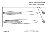
- the ballast may be injected along the back wall of the furnace.
- the ratio of ballast injected in the burners over the ballast injected into the furnace may depend on a number of operational criteria. This ratio may depend on the fuel characteristics. For example, with a difficult fuel (i.e. pitch difficult to atomize, wet fuels, fuels with a high content of incombustibles, fuels of a dangerous nature, etc.): the ballast injection ratio will be predominantly transferred towards the boiler, in order to allow and oxidant-rich combustion close to the burner. For a fuel with a high nitrogen content: to promote reaction mechanisms that reduce NOx formation, the ballast injection ratio will be displaced towards the burners, so as to create fuel-rich conditions at the flame.
- a difficult fuel i.e. pitch difficult to atomize, wet fuels, fuels with a high content of incombustibles, fuels of a dangerous nature, etc.
- the ballast injection ratio will be predominantly transferred towards the boiler, in order to allow and oxidant-rich combustion close to the burner.
- the ballast injection ratio will
- This ratio can also vary with boiler load, with a ratio displaced towards the boiler, in order to allow oxygen-rich conditions close to the burner to improve flame stability at low boiler load. Combined to this, the ratio may depend on operating conditions such as tube skin temperature, maximum flux measurement, and other operational criterial known to the skilled artisan.
- the present invention is a method for injecting shielding gas into a boiler comprising;
- said region is selected from the group consisting of:
- said element is selected from the group consisting of:
- the shielding gas streams may be located, oriented, and controlled such that the shielding gas is injected vertically parallel with and substantially adjacent to the walls of the combustion chamber.
- the shielding gas streams may be located, oriented, and controlled such that the shielding gas is injected vertically parallel with and substantially adjacent to the heat transfer elements positioned within the combustion chamber.
- the ballast streams may be located, oriented, and controlled such that the shielding gas is injected horizontally parallel and substantially adjacent to the heat transfer elements positioned within the combustion chamber.
- the ballast streams may be located, oriented, and controlled such that the shielding gas is injected horizontally parallel and substantially adjacent to the heat transfer elements positioned within the combustion chamber.
- the shielding gas streams may be located, oriented, and controlled such that the shielding gas is injected vertically parallel with and substantially adjacent to one or more zones within the combustion chamber where the heat flux exceeds a predetermined value.
- the shielding gas streams may be located, oriented, and controlled such that the shielding gas is injected in a direction substantially parallel to the direction of the combustion chamber jet.
- the shielding gas streams may be located, oriented, and controlled such that the shielding gas is injected in a direction substantially perpendicular to the direction of the combustion chamber jet.
- the shielding gas streams may be located, oriented, and controlled such that the shielding gas is injected in a direction substantially convergent to the direction of the combustion chamber jet.
- the feeding ports for the shielding gas streams into the combustion chamber may be located more than 1 meter away from the burner jet.
- the shielding gas streams may be injected such that at least one of the shielding gas streams has a swirl rate between 0,05 and 5, preferably between 0,26 and 1,73.
- This swirl rate is defined as I t over I a , I t and I a being respectively tangential and axial impulsions of the fluid rotated in the stream.
- the present invention may further comprise
- system data may be selected from the group consisting of:
- the present invention may further comprise;
- the sensors may measure a variable selected from the group consisting of wall temperature, tube skin temperature, water wall fluid temperature, tube fluid temperature, furnace gas temperature, and heat flux.
- the shielding gas may comprise recycled flue gas.
- the totality of injection of recycled flue gas into the boiler may be in the form of shielding gas.
- the total injection of recycled flue gas into the boiler may be shared among ballast gas injected at the burners level and in the form of shielding gas.
- the ballast gas injected at the burners level may be injected separately to an oxidant stream.
- the ballast gas injected at the burners level may be injected after being mixed with an oxidant stream.
- the shielding gas streams passing into the combustion chamber region may comprise at least one frequency with an amplitude of vibration, and wherein the boiler system comprises at least one natural frequency.
- the ratio between the lowest frequency created by at least one of the shielding gas injections and the lowest natural frequency of the boiler system may be comprised between 0 and 0,95 or between 1,05 and 100, and preferably between 0 and 0,6 or between 1,3 and 5.
- the flow of the different shielding gas injections may be controlled by the measure of the amplitude of the vibration at a location of the oxy-boiler selected from the group consisting of:
- the shielding gas streams may have a controlled composition.
- the shielding gas streams may have undergone a clean-up treatment before injection.
- the shielding gas streams may have undergone a partial clean-up treatment before injection, aiming specifically at reducing the concentration of certain components.
- the shielding gas streams may have undergone a partial clean-up treatment before injection, aiming specifically at reducing the concentration of corrosive components.
- the shielding gas streams may have undergone a total or partial drying, so as to reduce the moisture content of these streams.
- the shielding gas streams may be injected at temperatures between about -50°C to about 1500°C, preferably between about 100°C and about 250°C. In the present invention, the shielding gas streams may be injected at ambient temperature. In the present invention, the shielding gas streams may have undergone thermal exchange against other fluids before injection. In the present invention, the shielding gas streams may have undergone pre-heating before injection. In the present invention, the shielding gas streams may be injected at different temperature levels at each injection point.
Landscapes
- Engineering & Computer Science (AREA)
- Chemical & Material Sciences (AREA)
- Combustion & Propulsion (AREA)
- Mechanical Engineering (AREA)
- General Engineering & Computer Science (AREA)
Abstract
Description
- The present invention relates to a method for injecting fuel, oxidant and ballast into an oxycombustion boiler.
- In an oxycombustion boiler, in which fuel, oxidant and ballast are injected, it is possible to separate a portion of the ballast in order to introduce it into the boiler at different locations from the burner, or combustion chamber jet. By using a suitable injection arrangement of this type, a number of beneficial effects may be achieved. The profile of the heat transfer flux to the walls of the boiler is smoother and a "gas curtain" is created around the flame so as to spread the heat release along the combustion chamber. This 'gas curtain' is not to be confused with 'sweep gas' which is typically used for protecting flame detectors, out of service injectors, probes, etc. The 'gas curtain' protects the furnace tubes from direct contact with the flame. Greater physical separation of the fuel and oxidant injection compared with the ballast is obtained, thus allowing more direct contact between fuel and oxidant for better combustion of difficult fuels. The ballast may consist of recycled flue gases (whether cold or not), with the advantage of having flame radiation absorption properties with respect to the predominant gases CO2 and H2O, or other gases or gas mixtures.
- There are existing schemes that recycle ballast into various locations within a boiler. There exist systems using recycle injection into the burner or windbox; recycle injection into furnaces; recycle injection into the burner; and recycle, recreating a synthetic air (mixture of oxygen and recycle flue gases). This flue gas recycle is usually performed by separating one part of the main flue gas stream exiting a boiler, and redirecting it towards the boiler through appropriate ducts and impelled generally with a fan or a suction device, known to the skilled in the art.
- There are also existing schemes in which nitrogen is injected in a boiler separately from oxygen (as such described in
EP 1 517 085 A2 ), so as to create either nitrogen-poor or nitrogen rich atmospheres for the purpose of controlling NOx emissions. In the present invention, the shielding gas is meant to be essentially devoid of nitrogen, as this invention is directed toward oxy-combustion in boilers. The goal of this oxy-combustion in boilers is to produce an exhaust stream enriched in CO2, and thereby facilitating CO2 capture. Typical examples of shielding gas envisaged in the present invention are therefore flue gas recycle from oxy-combustion (composed mainly of CO2 and H2O), dried flue gas recycle from oxy-combustion (composed mainly of CO2, after condensation of moisture) or steam. - When the present invention is to be used for combustion with air as oxidant, for example at transient conditions for the oxy-boiler or at start-up of the oxy-boiler, a shielding gas stream may also be composed of flue gas recycle, but in such a case this stream would contain a non-negligible content of nitrogen (over 50% in volume). In other embodiment for this usage of air as oxidant, a shielding gas stream may even be air, which for efficiency reasons can be previously heated.
- There are other boiler schemes in which Over Fire Air (OFA) is injected separately from the burners to reduce NOx emissions. This should divide the incorporation of oxidant into the boiler so as to create at the burners a fuel-rich primary zone, while the rest of the oxidant is added at this OFA ports for achieving a complete combustion at a so-called burnout zone. An example is shown in the patent
US 5626085 A . In the present invention , thermal gas shielding of regions within the boiler is at issue, and not injections for affecting chemically the flame and the combustion phenomena. - The present invention utilizes the separation of ballast injection into the furnace from the oxygen injection into the burner. There may be an arrangement of the ballast injection into the boiler according to the flux profile. There may be the creation of a gaseous ballast offset, to ensure separation between the flame and the walls of the boiler. There may be the control of the burner ballast/boiler ballast injection ratio according to the various operating parameters (fuel characteristics, boiler operating conditions, temperature levels in the chamber, etc.). The flow of injected ballast (coming from the ratio of burner injection to boiler chamber injection) and the distribution of these injections will be different, depending on the desired effect.
- Turning now to
Figure 1 , one aspect of the present invention results in the smoothing, levelling or flattening of the flux profile on the walls of the burner. As may be seen in the figure, the transfer profile corresponding to an oxygen flame has a non-uniform shape. For an oxygen flame, the main component of this transfer is radiation, owing to the high flame core temperature and above all the gases that predominantly make up the oxycombustion flue gases, namely CO2 and H2O, radiating at high temperature. The non-homogeneous temperature distribution along the length of the flame results in a non-uniform heat flux along the corresponding length of the furnace wall. This results in non-linear heat transfer issues, potential concerns about furnace wall (or tube wall) temperatures and other problems regarding localized excessive temperature concentrations. - As indicated in
Figure 2 , the proposed way of making this flux more uniform is to inject the ballast along the side of the flame, along the side of the walls that would ordinarily be absorbing this heat, so as to effectively create a gas curtain. This ballast gas curtain may contain gases that are not transparent to the radiation (i.e. CO2, H2O, coming for example from a flue gas recycle), and therefore absorb the radiation of the flame due to the fact of being comparatively cooler. In one embodiment of the current invention, a greater ballast may be injected near the transfer peak to allow the height of the transfer peak to be reduced. - In one embodiment of the present invention a large amount of ballast gas may be injected with two operating positions (e.g. on/off), with the advantage of a simplified process and a simplified control scheme, and with the disadvantage of increased implementation complexity, potential flexibility issues, and the associated pressure drop through the system. In another embodiment of the present invention, a lesser amount of ballast gas injection may incorporate a flow rate regulation in order to end up with the desired flux smoothing performance, with the advantage of greater control and more predictable results, and the disadvantage of a more complex process and a more complex control scheme.
- In one embodiment of the present invention the ballast streams are injected vertically parallel with and substantially adjacent to the walls of the combustion chamber in a substantially downward direction. In one embodiment of the present invention the ballast streams are injected vertically parallel with and substantially adjacent to the walls of the combustion chamber in a substantially upward direction. In one embodiment of the present invention the ballast streams are injected horizontally parallel and substantially adjacent to the floor of the combustion chamber. In one embodiment of the present invention the ballast streams are injected horizontally parallel and substantially adjacent to the ceiling of the combustion chamber. In one embodiment of the present invention system data is provided to a control system, and the control system then controls the injection of the ballast streams. The system data may be fuel type, fuel characteristics, boiler operating conditions, exiting flue gas composition, or exiting flue gas temperature. Ballast injection streams rate and distribution can vary as well with boiler load.
- In one embodiment of the present invention sensors are mounted in the walls of the combustion chamber. These sensors provide input to a control system. The control system then controls the injection of the ballast streams. The sensors may measure wall temperature, tube skin temperature, water wall fluid temperature, tube fluid temperature, furnace gas temperature, heat flux into the furnace wall, heat flux into the tubes or heat flux into the water walls.
- The ballast injection regulation is designed within this context on the flow rate and as a function of the flux measurements on the walls, but it may also take place as a function of the tube skin temperatures, or overall parameters such as the incoming power or the boiler combustion temperature outlet temperature, once the typical flux profile has been established for a combustion chamber configuration and a burner design.
- In another embodiment of the present invention, a gaseous offset may also be produced. This offset may be envisaged either for protecting the walls of the boiler from direct contact of the end of the flame (impingement) or for protecting them from lateral contact of the flame. Direct contact of the flame on the walls has devastating effects on the integrity of the metal tubes that make up the walls of the chamber in usual boiler configurations. The points of possible impingement can be predicted in advance, thereby facilitating the arrangement of the injections into the boiler. As indicated in
Figure 2 , in order to avoid lateral contact of the flames on the tubes, the ballast gas may be injected in parallel with the walls. This configuration may profit from the flux smoothing effect described above. As indicated inFigure 3 , in order to avoid direct contact of the flames, which is more probable and at the same time the most damaging, which has the greatest chance of occurring at the end of the flame, the ballast may be injected along the back wall of the furnace. - The ratio of ballast injected in the burners over the ballast injected into the furnace, may depend on a number of operational criteria. This ratio may depend on the fuel characteristics. For example, with a difficult fuel (i.e. pitch difficult to atomize, wet fuels, fuels with a high content of incombustibles, fuels of a dangerous nature, etc.): the ballast injection ratio will be predominantly transferred towards the boiler, in order to allow and oxidant-rich combustion close to the burner. For a fuel with a high nitrogen content: to promote reaction mechanisms that reduce NOx formation, the ballast injection ratio will be displaced towards the burners, so as to create fuel-rich conditions at the flame. This ratio can also vary with boiler load, with a ratio displaced towards the boiler, in order to allow oxygen-rich conditions close to the burner to improve flame stability at low boiler load. Combined to this, the ratio may depend on operating conditions such as tube skin temperature, maximum flux measurement, and other operational criterial known to the skilled artisan.
- Other features and advantages of the invention will appear from a reading of the description that follows. Embodiments of the invention are provided as non-limiting examples.
-
Figure 1 a schematic representation of the variation in heat flux experienced within the side walls of a furnace of a typical boiler as a function of flame profile. -
Figure 2 is a schematic representation of the variation in heat flux within the side walls of furnace of a typical boiler, as a function of flame profile, as modified by one embodiment of the present invention. -
Figure 3 is a schematic representation one aspect of the present invention. - The present invention is a method for injecting shielding gas into a boiler comprising;
- feeding at least one fuel stream and at least one oxidant stream, essentially devoid of nitrogen, to a combustion chamber wherein the fuel is substantially combusted to produce at least one combustion chamber jet and flue gas,
- passing into a region of the combustion chamber a plurality of shielding gas streams, wherein the shielding gas streams are located, oriented, and controlled in a manner appropriate to protect an element in the region.
- In the present invention said region is selected from the group consisting of:
- the combustion chamber,
- a zone within the combustion chamber of predominantly radiant heat transfer,
- a zone within the combustion chamber of maximum heat flux,
- a zone within the combustion chamber where the heat flux exceeds a predetermined value,
- a zone within the combustion chamber where the flue gas temperature is at a maximum, and
- a zone within the combustion chamber where the flue gas temperature exceeds a predetermined value.
- In the present invention, said element is selected from the group consisting of:
- the walls of the combustion chamber,
- the sides of the combustion chamber,
- heat transfer elements positioned within the combustion chamber,
- heat transfer elements positioned within a zone of predominantly radiant heat transfer within the combustion chamber, and
- the boiler elements in contact with the flue gas.
- In the present invention, the shielding gas streams may be located, oriented, and controlled such that the shielding gas is injected vertically parallel with and substantially adjacent to the walls of the combustion chamber. In the present invention, the shielding gas streams may be located, oriented, and controlled such that the shielding gas is injected vertically parallel with and substantially adjacent to the heat transfer elements positioned within the combustion chamber. In the present invention the ballast streams may be located, oriented, and controlled such that the shielding gas is injected horizontally parallel and substantially adjacent to the heat transfer elements positioned within the combustion chamber. In the present invention the ballast streams may be located, oriented, and controlled such that the shielding gas is injected horizontally parallel and substantially adjacent to the heat transfer elements positioned within the combustion chamber.
- In the present invention, the shielding gas streams may be located, oriented, and controlled such that the shielding gas is injected vertically parallel with and substantially adjacent to one or more zones within the combustion chamber where the heat flux exceeds a predetermined value. In the present invention, the shielding gas streams may be located, oriented, and controlled such that the shielding gas is injected in a direction substantially parallel to the direction of the combustion chamber jet.
- In the present invention, the shielding gas streams may be located, oriented, and controlled such that the shielding gas is injected in a direction substantially perpendicular to the direction of the combustion chamber jet. In the present invention, the shielding gas streams may be located, oriented, and controlled such that the shielding gas is injected in a direction substantially convergent to the direction of the combustion chamber jet. In the present invention, the feeding ports for the shielding gas streams into the combustion chamber may be located more than 1 meter away from the burner jet.
- In the present invention, the shielding gas streams may be injected such that at least one of the shielding gas streams has a swirl rate between 0,05 and 5, preferably between 0,26 and 1,73. This swirl rate is defined as It over Ia, It and Ia being respectively tangential and axial impulsions of the fluid rotated in the stream.
- The present invention may further comprise
- providing system data into a control system,
- controlling the injection of the shielding gas streams with this control system.
- In the present invention, the system data may be selected from the group consisting of:
- fuel type,
- fuel characteristics,
- fuel flows,
- oxidant characteristics,
- oxidant flows,
- ballast gas characteristics to the burners,
- ballast gas flows to the burners,
- boiler operating conditions,
- exiting flue gas composition, and
- exiting flue gas temperature.
- The present invention may further comprise;
- mounting sensors in or on the elements of the combustion chamber,
- inputting the output of the sensors into a control system,
- controlling the injection of the shielding gas streams with this control system.
- In the present invention, the sensors may measure a variable selected from the group consisting of wall temperature, tube skin temperature, water wall fluid temperature, tube fluid temperature, furnace gas temperature, and heat flux. In the present invention, the shielding gas may comprise recycled flue gas. In the present invention, the totality of injection of recycled flue gas into the boiler may be in the form of shielding gas.
- In the present invention, the total injection of recycled flue gas into the boiler may be shared among ballast gas injected at the burners level and in the form of shielding gas. In the present invention, the ballast gas injected at the burners level may be injected separately to an oxidant stream. In the present invention, the ballast gas injected at the burners level may be injected after being mixed with an oxidant stream.
- In the present invention, the shielding gas streams passing into the combustion chamber region may comprise at least one frequency with an amplitude of vibration, and wherein the boiler system comprises at least one natural frequency. In the present invention, the ratio between the lowest frequency created by at least one of the shielding gas injections and the lowest natural frequency of the boiler system may be comprised between 0 and 0,95 or between 1,05 and 100, and preferably between 0 and 0,6 or between 1,3 and 5.
- In the present invention, the flow of the different shielding gas injections may be controlled by the measure of the amplitude of the vibration at a location of the oxy-boiler selected from the group consisting of:
- burners,
- oxy-boiler walls,
- heat exchangers,
- ducts,
- stack,
- fans.
- In the present invention, the shielding gas streams may have a controlled composition. In the present invention, the shielding gas streams may have undergone a clean-up treatment before injection. In the present invention, the shielding gas streams may have undergone a partial clean-up treatment before injection, aiming specifically at reducing the concentration of certain components. In the present invention, the shielding gas streams may have undergone a partial clean-up treatment before injection, aiming specifically at reducing the concentration of corrosive components. In the present invention, the shielding gas streams may have undergone a total or partial drying, so as to reduce the moisture content of these streams.
- In the present invention, the shielding gas streams may be injected at temperatures between about -50°C to about 1500°C, preferably between about 100°C and about 250°C. In the present invention, the shielding gas streams may be injected at ambient temperature. In the present invention, the shielding gas streams may have undergone thermal exchange against other fluids before injection. In the present invention, the shielding gas streams may have undergone pre-heating before injection. In the present invention, the shielding gas streams may be injected at different temperature levels at each injection point.
Claims (15)
- Method for injecting shielding gas into a boiler comprising;• feeding at least one fuel stream and at least one oxidant stream, essentially devoid of nitrogen, to a combustion chamber wherein the fuel is substantially combusted to produce at least one combustion chamber jet and flue gas,the improvement consisting of:• passing into a region of the combustion chamber a plurality of shielding gas streams, wherein the shielding gas streams are located, oriented, and controlled in a manner appropriate to protect an element in the region.
- The method of claim 1, wherein said region is selected from the group consisting of:• the combustion chamber,• a zone within the combustion chamber of predominantly radiant heat transfer,• a zone within the combustion chamber of maximum heat flux,• a zone within the combustion chamber where the heat flux exceeds a predetermined value,• a zone within the combustion chamber where the flue gas temperature is at a maximum, and• a zone within the combustion chamber where the flue gas temperature exceeds a predetermined value,• a zone within the combustion chamber where heat exchangers are placed.
- The method of claim 1, wherein said element is selected from the group consisting of:• the walls of the combustion chamber,• the sides of the combustion chamber,• heat transfer elements positioned within the combustion chamber,• heat transfer elements positioned within a zone of predominantly radiant heat transfer within the combustion chamber, and• the boiler elements in contact with the flue gas.
- The method of claim 1, wherein the shielding gas streams are located, oriented, and controlled such that the shielding gas is injected vertically parallel with and substantially adjacent to the walls of the combustion chamber.
- The method of claim 1, wherein the shielding gas streams are located, oriented, and controlled such that the shielding gas is injected in a direction substantially perpendicular or substantially parallel to the direction of the combustion chamber jet.
- The method of claim 1, wherein the shielding gas streams are located, oriented, and controlled such that the shielding gas is injected in a direction substantially convergent to the direction of the combustion chamber jet.
- The method of claim 1, wherein the shielding gas streams are injected such that at least one of the shielding gas streams has a swirl rate between 0,05 and 5, preferably between 0,26 and 1,73.
- The method of any of the above claims, further comprising• providing system data into a control system,• controlling the injection of the shielding gas streams with this control system.
- The method of claim 8, wherein the system data is selected from the group consisting of:• fuel type,• fuel characteristics,• fuel flows,• oxidant characteristics,• oxidant flows,• ballast gas characteristics to the burners,• ballast gas flows to the burners,• boiler operating conditions,• exiting flue gas composition, and• exiting flue gas temperature.
- The method of any of the above claims, further comprising• mounting sensors in or on the elements of the combustion chamber,• inputting the output of the sensors into a control system,• controlling the injection of the shielding gas streams with this control system.
- The method of claim 10, wherein the sensors measure a variable selected from the group consisting of wall temperature, tube skin temperature, water wall fluid temperature, tube fluid temperature, furnace gas temperature, and heat flux.
- The method of any of the above claims, wherein the shielding gas comprises recycled flue gas.
- The method of any of the above claims, wherein the shielding gas streams passing into the combustion chamber region comprises at least one frequency with an amplitude of vibration, and wherein the boiler system comprises at least one natural frequency.
- The method of claim 13 where the ratio between the lowest frequency created by at least one of the shielding gas injections and the lowest natural frequency of the boiler system is comprised between 0 and 0,95 or between 1,05 and 100, and preferably between 0 and 0,6 or between 1,3 and 5.
- The method of claim 14, wherein the flow of the different shielding gas injections is controlled by the measure of the amplitude of the vibration at a location of the oxy-boiler selected from the group consisting of:• burners,• oxy-boiler walls,• heat exchangers,• ducts,• stack,• fans.
Priority Applications (3)
| Application Number | Priority Date | Filing Date | Title |
|---|---|---|---|
| EP08167521.7A EP2180252B1 (en) | 2008-10-24 | 2008-10-24 | Method for injecting ballast into an oxycombustion boiler |
| US12/578,621 US20100101465A1 (en) | 2008-10-24 | 2009-10-14 | Method For Injecting Ballast Into An Oxycombustion Boiler |
| PCT/EP2009/063456 WO2010046296A1 (en) | 2008-10-24 | 2009-10-15 | Method for injecting ballast into an oxycombustion boiler |
Applications Claiming Priority (1)
| Application Number | Priority Date | Filing Date | Title |
|---|---|---|---|
| EP08167521.7A EP2180252B1 (en) | 2008-10-24 | 2008-10-24 | Method for injecting ballast into an oxycombustion boiler |
Publications (2)
| Publication Number | Publication Date |
|---|---|
| EP2180252A1 true EP2180252A1 (en) | 2010-04-28 |
| EP2180252B1 EP2180252B1 (en) | 2016-03-23 |
Family
ID=40670911
Family Applications (1)
| Application Number | Title | Priority Date | Filing Date |
|---|---|---|---|
| EP08167521.7A Active EP2180252B1 (en) | 2008-10-24 | 2008-10-24 | Method for injecting ballast into an oxycombustion boiler |
Country Status (3)
| Country | Link |
|---|---|
| US (1) | US20100101465A1 (en) |
| EP (1) | EP2180252B1 (en) |
| WO (1) | WO2010046296A1 (en) |
Cited By (1)
| Publication number | Priority date | Publication date | Assignee | Title |
|---|---|---|---|---|
| US9297278B2 (en) | 2011-05-27 | 2016-03-29 | General Electric Company | Variable feedwater heater cycle |
Families Citing this family (1)
| Publication number | Priority date | Publication date | Assignee | Title |
|---|---|---|---|---|
| RU2630625C1 (en) * | 2016-06-03 | 2017-09-11 | Общество с ограниченной ответственностью научно-производственное предприятие "ИнтерПолярис" | Method of gas production in a gas generator and gas generator (versions) |
Citations (6)
| Publication number | Priority date | Publication date | Assignee | Title |
|---|---|---|---|---|
| DE19520720A1 (en) * | 1995-06-12 | 1996-12-19 | Evt Energie & Verfahrenstech | Method of generating steam |
| US5626085A (en) | 1995-12-26 | 1997-05-06 | Combustion Engineering, Inc. | Control of staged combustion, low NOx firing systems with single or multiple levels of overfire air |
| US6422160B1 (en) * | 1998-02-18 | 2002-07-23 | Loesche Gmbh | Apparatus for the combustion of vanadium-containing fuels |
| EP1517085A2 (en) | 2003-09-16 | 2005-03-23 | Praxair Technology, Inc. | Low NOx combustion using cogenerated oxygen and nitrogen streams |
| EP1580485A1 (en) * | 2002-12-12 | 2005-09-28 | Babcock-Hitachi Kabushiki Kaisha | Combustion apparatus and window box |
| WO2006054990A1 (en) * | 2004-11-12 | 2006-05-26 | Jupiter Oxygen Corporation | Device and method for boiler superheat temperature control |
Family Cites Families (32)
| Publication number | Priority date | Publication date | Assignee | Title |
|---|---|---|---|---|
| US3048131A (en) * | 1959-06-18 | 1962-08-07 | Babcock & Wilcox Co | Method for burning fuel |
| US3877440A (en) * | 1974-01-18 | 1975-04-15 | Foster Wheeler Corp | Curtain air system for vapor generators |
| US4270467A (en) * | 1980-01-14 | 1981-06-02 | Enertherm, Inc. | Low mass flow waste fuel incinerator |
| JPS59180215A (en) * | 1983-03-30 | 1984-10-13 | Takuma Co Ltd | Clinker preventive device of municipal waste incinerator |
| JPH0229372Y2 (en) * | 1984-09-26 | 1990-08-07 | ||
| US5230868A (en) * | 1989-04-04 | 1993-07-27 | A. Ahlstrom Corporation | Fluidized bed reactor with protected fluid distributor |
| CA2018910C (en) * | 1989-06-16 | 2000-02-22 | Masaaki Furukawa | Method of controlling combustion in a furnace |
| US5010827A (en) * | 1990-05-08 | 1991-04-30 | Wyerehaeuser Company | Apparatus for detecting carryover particles in the interior of a furnace |
| TW235335B (en) * | 1991-11-05 | 1994-12-01 | Mitsubishi Heavy Ind Ltd | |
| US5368471A (en) * | 1991-11-20 | 1994-11-29 | The Babcock & Wilcox Company | Method and apparatus for use in monitoring and controlling a black liquor recovery furnace |
| US5915310A (en) * | 1995-07-27 | 1999-06-29 | Consolidated Natural Gas Service Company | Apparatus and method for NOx reduction by selective injection of natural gas jets in flue gas |
| US5807418A (en) * | 1996-05-21 | 1998-09-15 | Praxair Technology, Inc. | Energy recovery in oxygen-fired glass melting furnaces |
| US5746144A (en) * | 1996-06-03 | 1998-05-05 | Duquesne Light Company | Method and apparatus for nox reduction by upper furnace injection of coal water slurry |
| US5809913A (en) * | 1996-10-15 | 1998-09-22 | Cinergy Technology, Inc. | Corrosion protection for utility boiler side walls |
| US5937772A (en) * | 1997-07-30 | 1999-08-17 | Institute Of Gas Technology | Reburn process |
| JP2000065305A (en) * | 1998-08-20 | 2000-03-03 | Hitachi Ltd | Once-through boiler |
| US6213032B1 (en) * | 1999-08-30 | 2001-04-10 | Energy Systems Associates | Use of oil water emulsion as a reburn fuel |
| AU2000226581A1 (en) * | 2000-02-18 | 2001-08-27 | Niro A/S | A method and apparatus for processing a pulverulent or particulate material |
| US6450108B2 (en) * | 2000-03-24 | 2002-09-17 | Praxair Technology, Inc. | Fuel and waste fluid combustion system |
| US6436737B1 (en) * | 2000-06-29 | 2002-08-20 | Sun Microsystems, Inc. | Method for reducing soft error rates in semiconductor devices |
| US6382958B1 (en) * | 2000-07-12 | 2002-05-07 | Praxair Technology, Inc. | Air separation method and system for producing oxygen to support combustion in a heat consuming device |
| CN1265119C (en) * | 2001-01-09 | 2006-07-19 | 阿部俊广 | Garbage incineration method and device thereof |
| US6478948B2 (en) * | 2001-02-26 | 2002-11-12 | Esa Corrosion Solutions, Ltd. | Method of monitoring and controlling corrosion of furnace boiler tubes |
| US6935251B2 (en) * | 2002-02-15 | 2005-08-30 | American Air Liquide, Inc. | Steam-generating combustion system and method for emission control using oxygen enhancement |
| EP1338848B1 (en) * | 2002-02-25 | 2015-09-02 | L'Air Liquide Société Anonyme pour l'Etude et l'Exploitation des Procédés Georges Claude | Method and apparatus for integrated air separation and heat recovery in a furnace |
| CA2429838C (en) * | 2003-05-29 | 2009-02-17 | Colin Maccallum | Method and apparatus for a simplified primary air system for improving fluid flow and gas mixing in recovery boilers |
| JP4466232B2 (en) * | 2004-06-28 | 2010-05-26 | 株式会社日立製作所 | Boiler deterioration diagnosis method, apparatus, system, and recording medium recording program |
| FI116541B (en) * | 2004-09-24 | 2005-12-15 | Kvaerner Power Oy | Erosion protection of circulating fluidized bed boiler |
| US7581945B2 (en) * | 2005-11-30 | 2009-09-01 | General Electric Company | System, method, and article of manufacture for adjusting CO emission levels at predetermined locations in a boiler system |
| US7475646B2 (en) * | 2005-11-30 | 2009-01-13 | General Electric Company | System and method for decreasing a rate of slag formation at predetermined locations in a boiler system |
| US7833296B2 (en) * | 2006-10-02 | 2010-11-16 | Clark Steve L | Reduced-emission gasification and oxidation of hydrocarbon materials for power generation |
| RU2469241C2 (en) * | 2007-02-02 | 2012-12-10 | Инфилко Дегремон, Инк. | Device and methods for combustion of waste water mud in furnace |
-
2008
- 2008-10-24 EP EP08167521.7A patent/EP2180252B1/en active Active
-
2009
- 2009-10-14 US US12/578,621 patent/US20100101465A1/en not_active Abandoned
- 2009-10-15 WO PCT/EP2009/063456 patent/WO2010046296A1/en not_active Ceased
Patent Citations (6)
| Publication number | Priority date | Publication date | Assignee | Title |
|---|---|---|---|---|
| DE19520720A1 (en) * | 1995-06-12 | 1996-12-19 | Evt Energie & Verfahrenstech | Method of generating steam |
| US5626085A (en) | 1995-12-26 | 1997-05-06 | Combustion Engineering, Inc. | Control of staged combustion, low NOx firing systems with single or multiple levels of overfire air |
| US6422160B1 (en) * | 1998-02-18 | 2002-07-23 | Loesche Gmbh | Apparatus for the combustion of vanadium-containing fuels |
| EP1580485A1 (en) * | 2002-12-12 | 2005-09-28 | Babcock-Hitachi Kabushiki Kaisha | Combustion apparatus and window box |
| EP1517085A2 (en) | 2003-09-16 | 2005-03-23 | Praxair Technology, Inc. | Low NOx combustion using cogenerated oxygen and nitrogen streams |
| WO2006054990A1 (en) * | 2004-11-12 | 2006-05-26 | Jupiter Oxygen Corporation | Device and method for boiler superheat temperature control |
Cited By (1)
| Publication number | Priority date | Publication date | Assignee | Title |
|---|---|---|---|---|
| US9297278B2 (en) | 2011-05-27 | 2016-03-29 | General Electric Company | Variable feedwater heater cycle |
Also Published As
| Publication number | Publication date |
|---|---|
| WO2010046296A1 (en) | 2010-04-29 |
| EP2180252B1 (en) | 2016-03-23 |
| US20100101465A1 (en) | 2010-04-29 |
Similar Documents
| Publication | Publication Date | Title |
|---|---|---|
| CN111051776B (en) | Low NO X CO burner method and apparatus | |
| CA2827331C (en) | Low nox combustion process and burner therefor | |
| US3890084A (en) | Method for reducing burner exhaust emissions | |
| US20090181333A1 (en) | Three Stage Low NOx Burner System With Controlled Stage Air Separation | |
| EP2894405B1 (en) | Sequential combustion arrangement with dilution gas | |
| WO2014029512A2 (en) | Sequential combustion with dilution gas mixer | |
| CN107036084B (en) | Gas boiler | |
| US5551869A (en) | Gas staged burner | |
| US9593848B2 (en) | Non-symmetrical low NOx burner apparatus and method | |
| US6287111B1 (en) | Low NOx boilers, heaters, systems and methods | |
| US20120244479A1 (en) | Combustion System Using Recycled Flue Gas to Boost Overfire Air | |
| EP2588809B1 (en) | Method and system for low-emission incineration of low-calorific waste gas | |
| EP2180252B1 (en) | Method for injecting ballast into an oxycombustion boiler | |
| CA2036654C (en) | Process and apparatus for reducing no_ emissions from combustion devices | |
| KR102226636B1 (en) | Low-NOx flare stack | |
| CA2753770A1 (en) | Furnace heat exchanger | |
| US9982886B2 (en) | Flue gas recycle system with fixed orifices | |
| JP2005521026A (en) | Removable ignition port plug for use in burners | |
| BR112016002457B1 (en) | BURNER ASSEMBLY AND METHOD FOR COMBUSTING GASEOUS OR LIQUID FUEL TO HEAT AN INDUSTRIAL OVEN | |
| CN213362460U (en) | Low-nitrogen combustion system | |
| JP2509994Y2 (en) | Gas duct burner for reheating | |
| KR100395783B1 (en) | Premix combustion device of boiler | |
| CN201425301Y (en) | Flat flame gas burner with low NOx emission | |
| JP5958856B2 (en) | CO boiler | |
| KR102236937B1 (en) | Stage Combustion Firing Burner for Gas |
Legal Events
| Date | Code | Title | Description |
|---|---|---|---|
| PUAI | Public reference made under article 153(3) epc to a published international application that has entered the european phase |
Free format text: ORIGINAL CODE: 0009012 |
|
| AK | Designated contracting states |
Kind code of ref document: A1 Designated state(s): AT BE BG CH CY CZ DE DK EE ES FI FR GB GR HR HU IE IS IT LI LT LU LV MC MT NL NO PL PT RO SE SI SK TR |
|
| AX | Request for extension of the european patent |
Extension state: AL BA MK RS |
|
| 17P | Request for examination filed |
Effective date: 20101028 |
|
| 17Q | First examination report despatched |
Effective date: 20101201 |
|
| AKX | Designation fees paid |
Designated state(s): AT BE BG CH CY CZ DE DK EE ES FI FR GB GR HR HU IE IS IT LI LT LU LV MC MT NL NO PL PT RO SE SI SK TR |
|
| GRAP | Despatch of communication of intention to grant a patent |
Free format text: ORIGINAL CODE: EPIDOSNIGR1 |
|
| INTG | Intention to grant announced |
Effective date: 20150930 |
|
| GRAS | Grant fee paid |
Free format text: ORIGINAL CODE: EPIDOSNIGR3 |
|
| GRAA | (expected) grant |
Free format text: ORIGINAL CODE: 0009210 |
|
| AK | Designated contracting states |
Kind code of ref document: B1 Designated state(s): AT BE BG CH CY CZ DE DK EE ES FI FR GB GR HR HU IE IS IT LI LT LU LV MC MT NL NO PL PT RO SE SI SK TR |
|
| REG | Reference to a national code |
Ref country code: GB Ref legal event code: FG4D |
|
| REG | Reference to a national code |
Ref country code: CH Ref legal event code: EP |
|
| REG | Reference to a national code |
Ref country code: AT Ref legal event code: REF Ref document number: 783533 Country of ref document: AT Kind code of ref document: T Effective date: 20160415 |
|
| REG | Reference to a national code |
Ref country code: IE Ref legal event code: FG4D |
|
| REG | Reference to a national code |
Ref country code: DE Ref legal event code: R096 Ref document number: 602008043013 Country of ref document: DE |
|
| REG | Reference to a national code |
Ref country code: LT Ref legal event code: MG4D |
|
| REG | Reference to a national code |
Ref country code: NL Ref legal event code: MP Effective date: 20160323 |
|
| PG25 | Lapsed in a contracting state [announced via postgrant information from national office to epo] |
Ref country code: GR Free format text: LAPSE BECAUSE OF FAILURE TO SUBMIT A TRANSLATION OF THE DESCRIPTION OR TO PAY THE FEE WITHIN THE PRESCRIBED TIME-LIMIT Effective date: 20160624 Ref country code: FI Free format text: LAPSE BECAUSE OF FAILURE TO SUBMIT A TRANSLATION OF THE DESCRIPTION OR TO PAY THE FEE WITHIN THE PRESCRIBED TIME-LIMIT Effective date: 20160323 Ref country code: NO Free format text: LAPSE BECAUSE OF FAILURE TO SUBMIT A TRANSLATION OF THE DESCRIPTION OR TO PAY THE FEE WITHIN THE PRESCRIBED TIME-LIMIT Effective date: 20160623 |
|
| REG | Reference to a national code |
Ref country code: AT Ref legal event code: MK05 Ref document number: 783533 Country of ref document: AT Kind code of ref document: T Effective date: 20160323 |
|
| PG25 | Lapsed in a contracting state [announced via postgrant information from national office to epo] |
Ref country code: NL Free format text: LAPSE BECAUSE OF FAILURE TO SUBMIT A TRANSLATION OF THE DESCRIPTION OR TO PAY THE FEE WITHIN THE PRESCRIBED TIME-LIMIT Effective date: 20160323 Ref country code: SE Free format text: LAPSE BECAUSE OF FAILURE TO SUBMIT A TRANSLATION OF THE DESCRIPTION OR TO PAY THE FEE WITHIN THE PRESCRIBED TIME-LIMIT Effective date: 20160323 Ref country code: LV Free format text: LAPSE BECAUSE OF FAILURE TO SUBMIT A TRANSLATION OF THE DESCRIPTION OR TO PAY THE FEE WITHIN THE PRESCRIBED TIME-LIMIT Effective date: 20160323 Ref country code: LT Free format text: LAPSE BECAUSE OF FAILURE TO SUBMIT A TRANSLATION OF THE DESCRIPTION OR TO PAY THE FEE WITHIN THE PRESCRIBED TIME-LIMIT Effective date: 20160323 |
|
| PG25 | Lapsed in a contracting state [announced via postgrant information from national office to epo] |
Ref country code: EE Free format text: LAPSE BECAUSE OF FAILURE TO SUBMIT A TRANSLATION OF THE DESCRIPTION OR TO PAY THE FEE WITHIN THE PRESCRIBED TIME-LIMIT Effective date: 20160323 Ref country code: PL Free format text: LAPSE BECAUSE OF FAILURE TO SUBMIT A TRANSLATION OF THE DESCRIPTION OR TO PAY THE FEE WITHIN THE PRESCRIBED TIME-LIMIT Effective date: 20160323 Ref country code: IS Free format text: LAPSE BECAUSE OF FAILURE TO SUBMIT A TRANSLATION OF THE DESCRIPTION OR TO PAY THE FEE WITHIN THE PRESCRIBED TIME-LIMIT Effective date: 20160723 |
|
| PG25 | Lapsed in a contracting state [announced via postgrant information from national office to epo] |
Ref country code: CZ Free format text: LAPSE BECAUSE OF FAILURE TO SUBMIT A TRANSLATION OF THE DESCRIPTION OR TO PAY THE FEE WITHIN THE PRESCRIBED TIME-LIMIT Effective date: 20160323 Ref country code: AT Free format text: LAPSE BECAUSE OF FAILURE TO SUBMIT A TRANSLATION OF THE DESCRIPTION OR TO PAY THE FEE WITHIN THE PRESCRIBED TIME-LIMIT Effective date: 20160323 Ref country code: RO Free format text: LAPSE BECAUSE OF FAILURE TO SUBMIT A TRANSLATION OF THE DESCRIPTION OR TO PAY THE FEE WITHIN THE PRESCRIBED TIME-LIMIT Effective date: 20160323 Ref country code: SK Free format text: LAPSE BECAUSE OF FAILURE TO SUBMIT A TRANSLATION OF THE DESCRIPTION OR TO PAY THE FEE WITHIN THE PRESCRIBED TIME-LIMIT Effective date: 20160323 Ref country code: PT Free format text: LAPSE BECAUSE OF FAILURE TO SUBMIT A TRANSLATION OF THE DESCRIPTION OR TO PAY THE FEE WITHIN THE PRESCRIBED TIME-LIMIT Effective date: 20160725 Ref country code: ES Free format text: LAPSE BECAUSE OF FAILURE TO SUBMIT A TRANSLATION OF THE DESCRIPTION OR TO PAY THE FEE WITHIN THE PRESCRIBED TIME-LIMIT Effective date: 20160323 |
|
| PG25 | Lapsed in a contracting state [announced via postgrant information from national office to epo] |
Ref country code: BE Free format text: LAPSE BECAUSE OF FAILURE TO SUBMIT A TRANSLATION OF THE DESCRIPTION OR TO PAY THE FEE WITHIN THE PRESCRIBED TIME-LIMIT Effective date: 20160323 Ref country code: IT Free format text: LAPSE BECAUSE OF FAILURE TO SUBMIT A TRANSLATION OF THE DESCRIPTION OR TO PAY THE FEE WITHIN THE PRESCRIBED TIME-LIMIT Effective date: 20160323 |
|
| REG | Reference to a national code |
Ref country code: DE Ref legal event code: R097 Ref document number: 602008043013 Country of ref document: DE |
|
| PLBE | No opposition filed within time limit |
Free format text: ORIGINAL CODE: 0009261 |
|
| STAA | Information on the status of an ep patent application or granted ep patent |
Free format text: STATUS: NO OPPOSITION FILED WITHIN TIME LIMIT |
|
| PG25 | Lapsed in a contracting state [announced via postgrant information from national office to epo] |
Ref country code: DK Free format text: LAPSE BECAUSE OF FAILURE TO SUBMIT A TRANSLATION OF THE DESCRIPTION OR TO PAY THE FEE WITHIN THE PRESCRIBED TIME-LIMIT Effective date: 20160323 |
|
| PG25 | Lapsed in a contracting state [announced via postgrant information from national office to epo] |
Ref country code: BG Free format text: LAPSE BECAUSE OF FAILURE TO SUBMIT A TRANSLATION OF THE DESCRIPTION OR TO PAY THE FEE WITHIN THE PRESCRIBED TIME-LIMIT Effective date: 20160623 |
|
| 26N | No opposition filed |
Effective date: 20170102 |
|
| PG25 | Lapsed in a contracting state [announced via postgrant information from national office to epo] |
Ref country code: SI Free format text: LAPSE BECAUSE OF FAILURE TO SUBMIT A TRANSLATION OF THE DESCRIPTION OR TO PAY THE FEE WITHIN THE PRESCRIBED TIME-LIMIT Effective date: 20160323 |
|
| REG | Reference to a national code |
Ref country code: CH Ref legal event code: PL |
|
| REG | Reference to a national code |
Ref country code: IE Ref legal event code: MM4A |
|
| REG | Reference to a national code |
Ref country code: FR Ref legal event code: ST Effective date: 20170630 |
|
| PG25 | Lapsed in a contracting state [announced via postgrant information from national office to epo] |
Ref country code: CH Free format text: LAPSE BECAUSE OF NON-PAYMENT OF DUE FEES Effective date: 20161031 Ref country code: FR Free format text: LAPSE BECAUSE OF NON-PAYMENT OF DUE FEES Effective date: 20161102 Ref country code: LI Free format text: LAPSE BECAUSE OF NON-PAYMENT OF DUE FEES Effective date: 20161031 |
|
| PG25 | Lapsed in a contracting state [announced via postgrant information from national office to epo] |
Ref country code: LU Free format text: LAPSE BECAUSE OF NON-PAYMENT OF DUE FEES Effective date: 20161024 |
|
| PG25 | Lapsed in a contracting state [announced via postgrant information from national office to epo] |
Ref country code: IE Free format text: LAPSE BECAUSE OF NON-PAYMENT OF DUE FEES Effective date: 20161024 |
|
| PG25 | Lapsed in a contracting state [announced via postgrant information from national office to epo] |
Ref country code: CY Free format text: LAPSE BECAUSE OF FAILURE TO SUBMIT A TRANSLATION OF THE DESCRIPTION OR TO PAY THE FEE WITHIN THE PRESCRIBED TIME-LIMIT Effective date: 20160323 Ref country code: HU Free format text: LAPSE BECAUSE OF FAILURE TO SUBMIT A TRANSLATION OF THE DESCRIPTION OR TO PAY THE FEE WITHIN THE PRESCRIBED TIME-LIMIT; INVALID AB INITIO Effective date: 20081024 |
|
| PG25 | Lapsed in a contracting state [announced via postgrant information from national office to epo] |
Ref country code: MT Free format text: LAPSE BECAUSE OF NON-PAYMENT OF DUE FEES Effective date: 20161031 Ref country code: MC Free format text: LAPSE BECAUSE OF FAILURE TO SUBMIT A TRANSLATION OF THE DESCRIPTION OR TO PAY THE FEE WITHIN THE PRESCRIBED TIME-LIMIT Effective date: 20160323 Ref country code: HR Free format text: LAPSE BECAUSE OF FAILURE TO SUBMIT A TRANSLATION OF THE DESCRIPTION OR TO PAY THE FEE WITHIN THE PRESCRIBED TIME-LIMIT Effective date: 20160323 Ref country code: TR Free format text: LAPSE BECAUSE OF FAILURE TO SUBMIT A TRANSLATION OF THE DESCRIPTION OR TO PAY THE FEE WITHIN THE PRESCRIBED TIME-LIMIT Effective date: 20160323 |
|
| PGFP | Annual fee paid to national office [announced via postgrant information from national office to epo] |
Ref country code: GB Payment date: 20231020 Year of fee payment: 16 |
|
| PGFP | Annual fee paid to national office [announced via postgrant information from national office to epo] |
Ref country code: DE Payment date: 20241021 Year of fee payment: 17 |
|
| GBPC | Gb: european patent ceased through non-payment of renewal fee |
Effective date: 20241024 |
|
| PG25 | Lapsed in a contracting state [announced via postgrant information from national office to epo] |
Ref country code: GB Free format text: LAPSE BECAUSE OF NON-PAYMENT OF DUE FEES Effective date: 20241024 |