EP2180156A1 - Injection system for injecting a reducing substance into an exhaust system of an internal combustion engine - Google Patents
Injection system for injecting a reducing substance into an exhaust system of an internal combustion engine Download PDFInfo
- Publication number
- EP2180156A1 EP2180156A1 EP08425691A EP08425691A EP2180156A1 EP 2180156 A1 EP2180156 A1 EP 2180156A1 EP 08425691 A EP08425691 A EP 08425691A EP 08425691 A EP08425691 A EP 08425691A EP 2180156 A1 EP2180156 A1 EP 2180156A1
- Authority
- EP
- European Patent Office
- Prior art keywords
- connecting tube
- injection system
- exhaust gases
- exhaust
- feeding aperture
- Prior art date
- Legal status (The legal status is an assumption and is not a legal conclusion. Google has not performed a legal analysis and makes no representation as to the accuracy of the status listed.)
- Withdrawn
Links
Images

Classifications
-
- F—MECHANICAL ENGINEERING; LIGHTING; HEATING; WEAPONS; BLASTING
- F01—MACHINES OR ENGINES IN GENERAL; ENGINE PLANTS IN GENERAL; STEAM ENGINES
- F01N—GAS-FLOW SILENCERS OR EXHAUST APPARATUS FOR MACHINES OR ENGINES IN GENERAL; GAS-FLOW SILENCERS OR EXHAUST APPARATUS FOR INTERNAL-COMBUSTION ENGINES
- F01N3/00—Exhaust or silencing apparatus having means for purifying, rendering innocuous, or otherwise treating exhaust
- F01N3/08—Exhaust or silencing apparatus having means for purifying, rendering innocuous, or otherwise treating exhaust for rendering innocuous
- F01N3/10—Exhaust or silencing apparatus having means for purifying, rendering innocuous, or otherwise treating exhaust for rendering innocuous by thermal or catalytic conversion of noxious components of exhaust
- F01N3/18—Exhaust or silencing apparatus having means for purifying, rendering innocuous, or otherwise treating exhaust for rendering innocuous by thermal or catalytic conversion of noxious components of exhaust characterised by methods of operation; Control
- F01N3/20—Exhaust or silencing apparatus having means for purifying, rendering innocuous, or otherwise treating exhaust for rendering innocuous by thermal or catalytic conversion of noxious components of exhaust characterised by methods of operation; Control specially adapted for catalytic conversion
- F01N3/206—Adding periodically or continuously substances to exhaust gases for promoting purification, e.g. catalytic material in liquid form, NOx reducing agents
- F01N3/2066—Selective catalytic reduction [SCR]
-
- F—MECHANICAL ENGINEERING; LIGHTING; HEATING; WEAPONS; BLASTING
- F01—MACHINES OR ENGINES IN GENERAL; ENGINE PLANTS IN GENERAL; STEAM ENGINES
- F01N—GAS-FLOW SILENCERS OR EXHAUST APPARATUS FOR MACHINES OR ENGINES IN GENERAL; GAS-FLOW SILENCERS OR EXHAUST APPARATUS FOR INTERNAL-COMBUSTION ENGINES
- F01N2610/00—Adding substances to exhaust gases
- F01N2610/02—Adding substances to exhaust gases the substance being ammonia or urea
-
- F—MECHANICAL ENGINEERING; LIGHTING; HEATING; WEAPONS; BLASTING
- F01—MACHINES OR ENGINES IN GENERAL; ENGINE PLANTS IN GENERAL; STEAM ENGINES
- F01N—GAS-FLOW SILENCERS OR EXHAUST APPARATUS FOR MACHINES OR ENGINES IN GENERAL; GAS-FLOW SILENCERS OR EXHAUST APPARATUS FOR INTERNAL-COMBUSTION ENGINES
- F01N2610/00—Adding substances to exhaust gases
- F01N2610/14—Arrangements for the supply of substances, e.g. conduits
- F01N2610/1453—Sprayers or atomisers; Arrangement thereof in the exhaust apparatus
-
- Y—GENERAL TAGGING OF NEW TECHNOLOGICAL DEVELOPMENTS; GENERAL TAGGING OF CROSS-SECTIONAL TECHNOLOGIES SPANNING OVER SEVERAL SECTIONS OF THE IPC; TECHNICAL SUBJECTS COVERED BY FORMER USPC CROSS-REFERENCE ART COLLECTIONS [XRACs] AND DIGESTS
- Y02—TECHNOLOGIES OR APPLICATIONS FOR MITIGATION OR ADAPTATION AGAINST CLIMATE CHANGE
- Y02T—CLIMATE CHANGE MITIGATION TECHNOLOGIES RELATED TO TRANSPORTATION
- Y02T10/00—Road transport of goods or passengers
- Y02T10/10—Internal combustion engine [ICE] based vehicles
- Y02T10/12—Improving ICE efficiencies
Definitions
- the present invention relates to an injection system for injecting a reducing substance into an exhaust system of an internal combustion engine provided with exhaust gas post-treatment.
- Respecting such limits is particularly critical, especially for Diesel engines; for such a reason, it has been suggested to equip the exhaust system of a Diesel engine with a further SCR (Selective Catalytic Reduction) catalyser adapted to convert NO x (NO 2 or NO) molecules into nitrogen (N 2 ), which is an inert gas, and water (H 2 0).
- SCR Selective Catalytic Reduction
- N 2 nitrogen
- H 2 0 water
- the reaction of reducing NO x molecules into nitrogen (N) is difficult to be obtained without the use of an appropriate reducing agent, which is generally identified in ammonia (NH 3 ).
- the reducing agent must be injected into the exhaust system and upstream of the SCR catalyser so as to be mixed with the exhaust gases before entering the SCR catalyser.
- an electromagnetic injector completely equivalent to the electromagnetic injectors currently used for injecting fuel into internal combustion engines.
- an injection device which comprises a tank containing the aqueous urea solution and a pump which draws the pressurized aqueous urea solution from the tank to feed the electromagnetic injector by means of a feeding pipe, is used.
- a problem related to the injection of an aqueous urea solution into the exhaust system relates to the fact that the urea breakdown also determines the formation of isocyanic acid (HNCO), which may thicken and polymerize and thus be deposited on the internal walls of the exhaust system, which are arranged close to the electromagnetic injector, thus forming solid foulings which are difficult to be removed.
- HNCO isocyanic acid
- the action of the passive mixer is not able to appropriately prevent the formation of solid foulings on the internal walls of the exhaust system which are arranged close to the electromagnetic injector.
- an injection system for injecting a reducing substance into an exhaust system of an internal combustion engine is provided as claimed in the appended claims.
- numeral 1 indicates as a whole an exhaust system of an internal combustion engine 2 working according to the "Diesel" cycle (i.e. fed with diesel fuel or the like).
- the exhaust system 1 emits the gases produced by the combustion into the atmosphere and comprises an exhaust pipe 3 which departs from an exhaust manifold 4 of the internal combustion engine 2.
- An oxidizing catalyser 5 and a particulate filter 6 are arranged along the exhaust pipe 3; in figure 1 , the oxidizing catalyser 5 and the particulate filter 6 are arranged one after the other within a same, common tubular container.
- an SCR (Selective Catalytic Reduction) catalytic system 7 for post-treating NO x (NO and NO 2 ) molecules is arranged along the exhaust pipe 3 and downstream of the oxidizing catalyser 5.
- the SCR catalytic system 7 may comprise a single SCR catalyser 7, as shown in figure 1 , or may comprise a set (normally three) of catalysers, which jointly optimize the SCR function for post-treating NO x molecules.
- An injection system 8 is coupled with the exhaust pipe 3 immediately upstream of the catalytic system 7, which injection system 8 is adapted to inject a reducing additive, and specifically an aqueous urea solution (i.e. a solution of urea and water) into the exhaust pipe 3 itself.
- a reducing additive i.e. a solution of urea and water
- an aqueous urea solution i.e. a solution of urea and water
- HNCO isocyanic acid
- NH 3 ammonia
- ammonia works as a reducing agent within the catalytic system 7 to promote the breakdown reaction of NO x molecules into nitrogen (N 2 ) and water (H 2 O).
- a static mixer 9 is inserted along the exhaust pipe 3 and at the injection system 8, which static mixer serves the function of generating turbulences in the exhaust gases inside the exhaust pipe 3, so as to prevent the localized thickening of the isocyanic acid (which is formed during the urea breakdown) and thus to prevent the polymerization of the isocyanic acid itself and so as to increase the efficiency of the catalytic system 7, by making the dispersion of ammonia in the exhaust gases more homogenous.
- the static mixer 9 is arranged downstream of the injection system 8; alternatively, the static mixer 9 could be arranged upstream of the injection system 8.
- the injection system 8 comprises a tank 10 containing the aqueous urea solution, and a pump 11 which draws the pressurized aqueous urea solution from the tank 10 to feed an electromagnetic injector 12 adapted to inject the pressurized aqueous urea solution into the exhaust pipe 3.
- the electromagnetic injector 12 is fixed to the exhaust pipe 3 by means of an mounting device 13 which comprises a tubular supporting body 14, which is made of thermally conductive material (typically steel), accommodates the electromagnetic injector 12 therein, and at a lower end thereof is adapted to be butt-coupled with a tubular appendix 15 which laterally and obliquely protrudes from a connecting tube 16 which forms a part of the exhaust pipe 3.
- the connecting tube 16 is adapted to allow a flow of exhaust gas therein, is arranged upstream of the catalytic system 7, and forms a part of the exhaust pipe 3 which originates from the exhaust manifold 4 of the internal combustion engine 2.
- the connecting tube 16 has a through feeding aperture 17 obtained through a side wall 18 of the connecting tube 16; the electromagnetic injector 12 injects the aqueous urea solution into the connecting tube 16 through the through feeding aperture 17.
- the connecting tube 16 has the tubular appendix 15, which is arranged at the feeding aperture 17, overhangingly originates from the side surface of the connecting tube 16 itself, and accommodates the injector 12 at an opposite end of the feeding aperture 17.
- the connecting tube 16 has a reduction of its cross section for introducing exhaust gases at the through feeding aperture 17 obtained through the side wall 18 of the connecting tube 16.
- the connecting tube 16 has a minimum cross section for introducing exhaust gases close to a starting point of the feeding aperture 17 with respect to the advancing direction 19 of the exhaust gases; specifically, the connecting tube 16 has a minimum cross section for introducing exhaust gases at a starting point of the feeding aperture 17 with respect to the advancing direction 19 of the exhaust gases.
- the reduction of the cross section for introducing exhaust gases into the connecting tube 16 is obtained by means of a fin 20 inserted into the connecting tube 16.
- the reduction of the cross section for introducing exhaust gases into the connecting tube 16 is obtained by deforming the side wall 18 of the connecting tube 16.
- the tubular appendix 15 is inclined with respect to the connecting tube 16 so as to form an acute angle (approximately 20°-40°) with the advancing direction 19 of the exhaust gases and the tubular appendix 15 has a progressively increasing cross section from the end in which the injector 12 is accommodated to the through feeding aperture 17.
- the exhaust gases which flow through the connecting tube 16 must locally increase their advancing speed and accordingly reduce their pressure at the feeding aperture 17.
- Such a pressure reduction of the exhaust gases which flow through the connecting tube 16 at the feeding aperture 17 attracts the urea injected by the injector 12 towards the centre of the connecting tube 16 and therefore away from the side wall 18 of the connecting tube 16; in this manner, the isocyanic acid (HNCO) formed by the breakdown of the urea injected by the injector 12 is mixed with the exhaust gases and thus flows downstream of the connecting tube 16 and is not deposited on the side wall 18 of the connecting tube 16 (or worse, on the side wall of the tubular appendix 15).
- HNCO isocyanic acid
- the tubular appendix 15 has a cross section gradually increasing from the end in which the injector 12 is accommodated to the through feeding end 17; in this manner, the pressure of the urea injected by the injector 12 tends to progressively increase from the end in which the injector is accommodated 12 to the through feeding aperture 17, and is thus relatively high at the through feeding aperture 17. Therefore, the relatively high pressurized urea which is at the through feeding aperture 17 tends to go towards the connecting tube 16 which has a reduced pressure and is not deposited on the side wall of the tubular appendix 15.
- the above-described mounting device 13 has many advantages because it is simple and cost-effective to be constructed (in other words, it has minimum differences as compared to a similar, known mounting device), is particularly tough (thus has a very long working life and a very low risk of failures) and, above all, allows to achieve an effective mixing of urea and its components with the exhaust gases, thus avoiding the formation of solid foulings on the side wall 18 of the connecting tube 16 and on the side wall of the tubular appendix 15.
Landscapes
- Chemical & Material Sciences (AREA)
- Engineering & Computer Science (AREA)
- Chemical Kinetics & Catalysis (AREA)
- Health & Medical Sciences (AREA)
- Toxicology (AREA)
- Combustion & Propulsion (AREA)
- Mechanical Engineering (AREA)
- General Engineering & Computer Science (AREA)
- Exhaust Gas After Treatment (AREA)
Abstract
An injection system (8) for injecting a reducing substance into an exhaust system (2) of an internal combustion engine; the injection system (8) has: a connecting tube (16), which is adapted to allow a flow of exhaust gas therein, is arranged upstream of the catalytic system (7), and forms a part of an exhaust pipe (3) which originates from an exhaust manifold (4) of an internal combustion engine (2); and an injector (12), which is coupled with the connecting tube (16) for injecting an additive into the connecting tube (16) itself through a through feeding aperture (17) obtained through a side wall (18) of the connecting tube (16); the connecting tube (16) has a reduction of its cross section for introducing exhaust gases at the through feeding aperture (17) obtained through the side wall (18) of the connecting tube (16).
Description
- The present invention relates to an injection system for injecting a reducing substance into an exhaust system of an internal combustion engine provided with exhaust gas post-treatment.
- Future international standards related to the reduction of emissions of polluting gases produced by cars (the so-called "Euro5" and "Euro6" or "Tier2 Bin5" standards) cover a very low limit for NOx molecules which may be released into the atmosphere.
- Respecting such limits is particularly critical, especially for Diesel engines; for such a reason, it has been suggested to equip the exhaust system of a Diesel engine with a further SCR (Selective Catalytic Reduction) catalyser adapted to convert NOx (NO2 or NO) molecules into nitrogen (N2), which is an inert gas, and water (H20). The reaction of reducing NOx molecules into nitrogen (N) is difficult to be obtained without the use of an appropriate reducing agent, which is generally identified in ammonia (NH3). The reducing agent must be injected into the exhaust system and upstream of the SCR catalyser so as to be mixed with the exhaust gases before entering the SCR catalyser.
- However, storing ammonia inside a car is not advisable due to evident safety reasons related to the fact that ammonia is toxic. Therefore, it has been suggested to store and inject an aqueous urea solution, because urea breaks down into ammonia due to the exhaust gas heat and also in part due to catalysis.
- For injecting the aqueous urea solution upstream of the SCR catalyser, it has been suggested to use an electromagnetic injector completely equivalent to the electromagnetic injectors currently used for injecting fuel into internal combustion engines. In this manner, existing components of proven efficiency and reliability may be used, and thus there is no need to develop new components, with evident saving of both costs and time. Specifically, an injection device which comprises a tank containing the aqueous urea solution and a pump which draws the pressurized aqueous urea solution from the tank to feed the electromagnetic injector by means of a feeding pipe, is used.
- A problem related to the injection of an aqueous urea solution into the exhaust system relates to the fact that the urea breakdown also determines the formation of isocyanic acid (HNCO), which may thicken and polymerize and thus be deposited on the internal walls of the exhaust system, which are arranged close to the electromagnetic injector, thus forming solid foulings which are difficult to be removed. In order to avoid the polymerization of the isocyanic acid produced by the urea breakdown, it has been suggested to insert a passive mixer into the exhaust system and close to the urea injection area, which passive mixer prevents the localized thickening of the isocyanic acid and thus prevents the polymerization of the isocyanic acid itself by forming turbulences in the exhaust gases. However, it has been observed that the action of the passive mixer is not able to appropriately prevent the formation of solid foulings on the internal walls of the exhaust system which are arranged close to the electromagnetic injector.
- It is the object of the present invention to provide an injection system for injecting a reducing substance into an exhaust system of an internal combustion engine, which injection system is easy and cost-effective to be constructed, is free from the above-described drawbacks and, in particular, has no formation of solid foulings on the internal walls of the exhaust system which are arranged close to the injector.
- According to the present invention, an injection system for injecting a reducing substance into an exhaust system of an internal combustion engine is provided as claimed in the appended claims.
- The present invention will now be described with reference to the accompanying drawings, which illustrate some non-limitative embodiments thereof, in which:
-
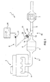
figure 1 is a diagrammatic view of an exhaust system of an internal combustion engine provided with exhaust gas post-treatment, and comprising an injection system for injecting a reducing substance made in accordance with the present invention; -
figure 2 is a diagrammatic, side section view of a connecting tube of the injection system infigure 1 ; -
figure 3 is a diagrammatic, perspective view of the connecting tube infigure 2 ; and -
figure 4 is a diagrammatic, side section view of a constructional variant of the connecting tube infigure 2 . - In
figure 1 , numeral 1 indicates as a whole an exhaust system of an internal combustion engine 2 working according to the "Diesel" cycle (i.e. fed with diesel fuel or the like). - The exhaust system 1 emits the gases produced by the combustion into the atmosphere and comprises an
exhaust pipe 3 which departs from an exhaust manifold 4 of the internal combustion engine 2. An oxidizingcatalyser 5 and a particulate filter 6 are arranged along theexhaust pipe 3; infigure 1 , the oxidizingcatalyser 5 and the particulate filter 6 are arranged one after the other within a same, common tubular container. - Furthermore, an SCR (Selective Catalytic Reduction)
catalytic system 7 for post-treating NOx (NO and NO2) molecules is arranged along theexhaust pipe 3 and downstream of the oxidizingcatalyser 5. The SCRcatalytic system 7 may comprise asingle SCR catalyser 7, as shown infigure 1 , or may comprise a set (normally three) of catalysers, which jointly optimize the SCR function for post-treating NOx molecules. - An
injection system 8 is coupled with theexhaust pipe 3 immediately upstream of thecatalytic system 7, whichinjection system 8 is adapted to inject a reducing additive, and specifically an aqueous urea solution (i.e. a solution of urea and water) into theexhaust pipe 3 itself. In use, due to the heat of the exhaust gases inside theexhaust pipe 3, the urea injected into theexhaust pipe 3 itself spontaneously breaks down into isocyanic acid (HNCO) and ammonia (NH3), which ammonia works as a reducing agent within thecatalytic system 7 to promote the breakdown reaction of NOx molecules into nitrogen (N2) and water (H2O). - A
static mixer 9 is inserted along theexhaust pipe 3 and at theinjection system 8, which static mixer serves the function of generating turbulences in the exhaust gases inside theexhaust pipe 3, so as to prevent the localized thickening of the isocyanic acid (which is formed during the urea breakdown) and thus to prevent the polymerization of the isocyanic acid itself and so as to increase the efficiency of thecatalytic system 7, by making the dispersion of ammonia in the exhaust gases more homogenous. In the embodiment shown infigure 1 , thestatic mixer 9 is arranged downstream of theinjection system 8; alternatively, thestatic mixer 9 could be arranged upstream of theinjection system 8. - The
injection system 8 comprises atank 10 containing the aqueous urea solution, and apump 11 which draws the pressurized aqueous urea solution from thetank 10 to feed anelectromagnetic injector 12 adapted to inject the pressurized aqueous urea solution into theexhaust pipe 3. Theelectromagnetic injector 12 is fixed to theexhaust pipe 3 by means of anmounting device 13 which comprises a tubular supportingbody 14, which is made of thermally conductive material (typically steel), accommodates theelectromagnetic injector 12 therein, and at a lower end thereof is adapted to be butt-coupled with atubular appendix 15 which laterally and obliquely protrudes from aconnecting tube 16 which forms a part of theexhaust pipe 3. The connectingtube 16 is adapted to allow a flow of exhaust gas therein, is arranged upstream of thecatalytic system 7, and forms a part of theexhaust pipe 3 which originates from the exhaust manifold 4 of the internal combustion engine 2. - As shown in
figure 2 , at the intersection with thetubular appendix 15, the connectingtube 16 has a throughfeeding aperture 17 obtained through aside wall 18 of theconnecting tube 16; theelectromagnetic injector 12 injects the aqueous urea solution into the connectingtube 16 through the throughfeeding aperture 17. In other words, the connectingtube 16 has thetubular appendix 15, which is arranged at thefeeding aperture 17, overhangingly originates from the side surface of the connectingtube 16 itself, and accommodates theinjector 12 at an opposite end of thefeeding aperture 17. - The connecting
tube 16 has a reduction of its cross section for introducing exhaust gases at thethrough feeding aperture 17 obtained through theside wall 18 of the connectingtube 16. According to a preferred embodiment, the connectingtube 16 has a minimum cross section for introducing exhaust gases close to a starting point of thefeeding aperture 17 with respect to the advancingdirection 19 of the exhaust gases; specifically, the connectingtube 16 has a minimum cross section for introducing exhaust gases at a starting point of thefeeding aperture 17 with respect to the advancingdirection 19 of the exhaust gases. - According to the embodiment shown in
figures 2 and 3 , the reduction of the cross section for introducing exhaust gases into the connectingtube 16 is obtained by means of afin 20 inserted into the connectingtube 16. According to the embodiment shown infigure 4 , the reduction of the cross section for introducing exhaust gases into the connectingtube 16 is obtained by deforming theside wall 18 of the connectingtube 16. - According to a preferred embodiment shown in
figures 2-4 , thetubular appendix 15 is inclined with respect to the connectingtube 16 so as to form an acute angle (approximately 20°-40°) with the advancingdirection 19 of the exhaust gases and thetubular appendix 15 has a progressively increasing cross section from the end in which theinjector 12 is accommodated to the throughfeeding aperture 17. - In virtue of the reduction of the cross section for introducing exhaust gases of the connecting
tube 16 at thefeeding aperture 17, the exhaust gases which flow through the connectingtube 16 must locally increase their advancing speed and accordingly reduce their pressure at thefeeding aperture 17. Such a pressure reduction of the exhaust gases which flow through the connectingtube 16 at the feeding aperture 17 (originated by the reduction of the cross section for introducing exhaust gases of the connecting tube 16) attracts the urea injected by theinjector 12 towards the centre of the connectingtube 16 and therefore away from theside wall 18 of the connectingtube 16; in this manner, the isocyanic acid (HNCO) formed by the breakdown of the urea injected by theinjector 12 is mixed with the exhaust gases and thus flows downstream of the connectingtube 16 and is not deposited on theside wall 18 of the connecting tube 16 (or worse, on the side wall of the tubular appendix 15). - As previously mentioned, according to a preferred embodiment, the
tubular appendix 15 has a cross section gradually increasing from the end in which theinjector 12 is accommodated to the throughfeeding end 17; in this manner, the pressure of the urea injected by theinjector 12 tends to progressively increase from the end in which the injector is accommodated 12 to the throughfeeding aperture 17, and is thus relatively high at the throughfeeding aperture 17. Therefore, the relatively high pressurized urea which is at thethrough feeding aperture 17 tends to go towards the connectingtube 16 which has a reduced pressure and is not deposited on the side wall of thetubular appendix 15. - The above-described
mounting device 13 has many advantages because it is simple and cost-effective to be constructed (in other words, it has minimum differences as compared to a similar, known mounting device), is particularly tough (thus has a very long working life and a very low risk of failures) and, above all, allows to achieve an effective mixing of urea and its components with the exhaust gases, thus avoiding the formation of solid foulings on theside wall 18 of the connectingtube 16 and on the side wall of thetubular appendix 15.
Claims (8)
- An injection system (8) for injecting a reducing substance into an exhaust system (1) of an internal combustion engine (2); the injection system (8) comprises:a connecting tube (16), which is adapted to allow a flow of exhaust gas therein, is arranged upstream of at least one catalytic system (7), and forms a part of an exhaust pipe (3) which originates from an exhaust manifold (4) of the internal combustion engine (2); andan injector (12), which is coupled with the connecting tube (16) for injecting an additive into the connecting tube (16) itself through a through feeding aperture (17) obtained through a side wall (18) of the connecting tube (16);the injection system (8) is characterized in that the connecting tube (16) has a reduction of its cross section for introducing exhaust gases at the through feeding aperture (17) obtained through the side wall (18) of the connecting tube (16).
- An injection system (8) according to claim 1, wherein the connecting tube (16) has a minimum cross section for introducing exhaust gases close to a starting point of the feeding aperture (17) with respect to the advancing direction (19) of the exhaust gases.
- An injection system (8) according to claim 2, wherein the connecting tube (16) has a minimum cross section for introducing exhaust gases at a starting point of the feeding aperture (17) with respect to the advancing direction (19) of the exhaust gases.
- An injection system (8) according to claim 1, 2 or 3, wherein the reduction of the cross section for introducing exhaust gases into the connecting tube (16) is obtained by deforming the side wall (18) of the connecting tube (16).
- An injection system (8) according to claim 1, 2 or 3, wherein the reduction of the cross section for introducing exhaust gases into the connecting tube (16) is obtained by means of a fin (20) inserted into the connecting tube (16).
- An injection system (8) according to any one of the claims from 1 to 5, wherein the connecting tube (16) has the tubular appendix (15), which is arranged at the feeding aperture (17), overhangingly originates from the side surface of the connecting tube (16) itself, and accommodates the injector (12) at an opposite end of the feeding aperture (17).
- An injection system (8) according to claim 6, wherein the tubular appendix (15) is inclined with respect to the connecting tube (16) so as to form an acute angle with the advancing direction (19) of the exhaust gases.
- An injection system (8) according to claim 6 or 7, wherein the tubular appendix (15) has a cross section progressively increasing from the end in which the injector (12) is accommodated to the through feeding aperture (17).
Priority Applications (1)
| Application Number | Priority Date | Filing Date | Title |
|---|---|---|---|
| EP08425691A EP2180156A1 (en) | 2008-10-24 | 2008-10-24 | Injection system for injecting a reducing substance into an exhaust system of an internal combustion engine |
Applications Claiming Priority (1)
| Application Number | Priority Date | Filing Date | Title |
|---|---|---|---|
| EP08425691A EP2180156A1 (en) | 2008-10-24 | 2008-10-24 | Injection system for injecting a reducing substance into an exhaust system of an internal combustion engine |
Publications (1)
| Publication Number | Publication Date |
|---|---|
| EP2180156A1 true EP2180156A1 (en) | 2010-04-28 |
Family
ID=40328273
Family Applications (1)
| Application Number | Title | Priority Date | Filing Date |
|---|---|---|---|
| EP08425691A Withdrawn EP2180156A1 (en) | 2008-10-24 | 2008-10-24 | Injection system for injecting a reducing substance into an exhaust system of an internal combustion engine |
Country Status (1)
| Country | Link |
|---|---|
| EP (1) | EP2180156A1 (en) |
Cited By (4)
| Publication number | Priority date | Publication date | Assignee | Title |
|---|---|---|---|---|
| JP2010203248A (en) * | 2009-02-27 | 2010-09-16 | Toyota Motor Corp | Exhaust pipe structure of internal combustion engine |
| ITBO20110532A1 (en) * | 2011-09-16 | 2013-03-17 | Magneti Marelli Spa | EXHAUST SYSTEM OF AN INTERNAL COMBUSTION ENGINE PROVIDED WITH POST-TREATMENT OF EXHAUST GAS |
| EP2581573A4 (en) * | 2010-06-11 | 2014-03-19 | Isuzu Motors Ltd | SYSTEM FOR INJECTING FUEL IN AN EXHAUST PIPE |
| US9790829B2 (en) | 2010-06-11 | 2017-10-17 | Isuzu Motors Limited | System for injecting fuel into exhaust pipe |
Citations (3)
| Publication number | Priority date | Publication date | Assignee | Title |
|---|---|---|---|---|
| DE102006015964A1 (en) * | 2006-04-05 | 2007-10-18 | Arvinmeritor Emissions Technologies Gmbh | Assembly for mixing a medium with the exhaust gas flow of a motor vehicle exhaust system |
| DE102007000375A1 (en) * | 2006-07-27 | 2008-01-31 | Denso Corp., Kariya | emission control device |
| JP2008208761A (en) * | 2007-02-26 | 2008-09-11 | Hino Motors Ltd | Mixing structure |
-
2008
- 2008-10-24 EP EP08425691A patent/EP2180156A1/en not_active Withdrawn
Patent Citations (3)
| Publication number | Priority date | Publication date | Assignee | Title |
|---|---|---|---|---|
| DE102006015964A1 (en) * | 2006-04-05 | 2007-10-18 | Arvinmeritor Emissions Technologies Gmbh | Assembly for mixing a medium with the exhaust gas flow of a motor vehicle exhaust system |
| DE102007000375A1 (en) * | 2006-07-27 | 2008-01-31 | Denso Corp., Kariya | emission control device |
| JP2008208761A (en) * | 2007-02-26 | 2008-09-11 | Hino Motors Ltd | Mixing structure |
Cited By (5)
| Publication number | Priority date | Publication date | Assignee | Title |
|---|---|---|---|---|
| JP2010203248A (en) * | 2009-02-27 | 2010-09-16 | Toyota Motor Corp | Exhaust pipe structure of internal combustion engine |
| EP2581573A4 (en) * | 2010-06-11 | 2014-03-19 | Isuzu Motors Ltd | SYSTEM FOR INJECTING FUEL IN AN EXHAUST PIPE |
| US9255516B2 (en) | 2010-06-11 | 2016-02-09 | Isuzu Motors Limited | System for injecting fuel into exhaust pipe |
| US9790829B2 (en) | 2010-06-11 | 2017-10-17 | Isuzu Motors Limited | System for injecting fuel into exhaust pipe |
| ITBO20110532A1 (en) * | 2011-09-16 | 2013-03-17 | Magneti Marelli Spa | EXHAUST SYSTEM OF AN INTERNAL COMBUSTION ENGINE PROVIDED WITH POST-TREATMENT OF EXHAUST GAS |
Similar Documents
| Publication | Publication Date | Title |
|---|---|---|
| JP4779959B2 (en) | Exhaust purification device | |
| KR101927787B1 (en) | Reductant delivery unit for selective catalytic reduction with freeze accommodation structure | |
| EP2860369B1 (en) | System and device for reducing reductant deposit formation in exhaust aftertreatment systems | |
| EP2116700B1 (en) | Injection method and device for injecting a reducing agent into an exhaust system of an internal combustion engine | |
| US9308495B2 (en) | Exhaust purifier | |
| EP1982756A1 (en) | An exhaust system of an internal combustion engine | |
| US8997463B2 (en) | Reductant delivery unit for automotive selective catalytic reduction with reducing agent heating | |
| AU2010332964B2 (en) | Method for dosing an urea based reducing agent into a gas exhaust stream | |
| US20090056319A1 (en) | Exhaust Aftertreatment System with Pre-Catalysis | |
| US8443595B2 (en) | Additive-agent diffusion plate in exhaust passage, structure of additive-agent diffusion plate, and exhaust system including additive-agent diffusion plate | |
| US8756918B2 (en) | Dosing module for dosing an urea based reducing agent into a gas exhaust stream | |
| CN104234801A (en) | An exhaust gas sampling device | |
| US20160245142A1 (en) | Reductant injector mount | |
| US20090100827A1 (en) | Exhaust gas purification apparatus for internal combustion engine | |
| EP2573349A1 (en) | Exhaust pipe | |
| EP3356661B1 (en) | Uniform flow distribution of a reductant | |
| JP2015212530A (en) | Injection device | |
| KR101175114B1 (en) | Mixer for automobile muffler | |
| KR101610067B1 (en) | Selective catalyst reduction device for exhaust system | |
| JP7314840B2 (en) | Exhaust structure | |
| US11247173B1 (en) | Two-stage mixer | |
| CN102505979A (en) | Connection device and integrated SCR (selective catalytic reduction) catalytic muffler | |
| EP3141297A1 (en) | Exhaust gas treatement device for an exhaust system of an internal combustion engine | |
| CN204312173U (en) | Vehicle SCR systems and reducing agent feeding mechanism thereof | |
| KR102324758B1 (en) | Dosing module for vehicle |
Legal Events
| Date | Code | Title | Description |
|---|---|---|---|
| PUAI | Public reference made under article 153(3) epc to a published international application that has entered the european phase |
Free format text: ORIGINAL CODE: 0009012 |
|
| AK | Designated contracting states |
Kind code of ref document: A1 Designated state(s): AT BE BG CH CY CZ DE DK EE ES FI FR GB GR HR HU IE IS IT LI LT LU LV MC MT NL NO PL PT RO SE SI SK TR |
|
| AX | Request for extension of the european patent |
Extension state: AL BA MK RS |
|
| AKY | No designation fees paid | ||
| REG | Reference to a national code |
Ref country code: DE Ref legal event code: 8566 |
|
| STAA | Information on the status of an ep patent application or granted ep patent |
Free format text: STATUS: THE APPLICATION IS DEEMED TO BE WITHDRAWN |
|
| 18D | Application deemed to be withdrawn |
Effective date: 20101029 |