EP2180006A2 - Labeled compound and detection method using the same - Google Patents
Labeled compound and detection method using the same Download PDFInfo
- Publication number
- EP2180006A2 EP2180006A2 EP09010826A EP09010826A EP2180006A2 EP 2180006 A2 EP2180006 A2 EP 2180006A2 EP 09010826 A EP09010826 A EP 09010826A EP 09010826 A EP09010826 A EP 09010826A EP 2180006 A2 EP2180006 A2 EP 2180006A2
- Authority
- EP
- European Patent Office
- Prior art keywords
- group
- bound
- labeled compound
- molecular chain
- compound
- Prior art date
- Legal status (The legal status is an assumption and is not a legal conclusion. Google has not performed a legal analysis and makes no representation as to the accuracy of the status listed.)
- Granted
Links
- 150000001875 compounds Chemical class 0.000 title claims abstract description 171
- 238000001514 detection method Methods 0.000 title claims abstract description 23
- 125000001997 phenyl group Chemical group [H]C1=C([H])C([H])=C(*)C([H])=C1[H] 0.000 claims abstract description 67
- -1 aromatic tertiary amine compound Chemical class 0.000 claims abstract description 59
- 108091034117 Oligonucleotide Proteins 0.000 claims abstract description 55
- 238000009739 binding Methods 0.000 claims abstract description 37
- 125000001624 naphthyl group Chemical group 0.000 claims abstract description 29
- 125000004957 naphthylene group Chemical group 0.000 claims abstract description 29
- 125000000843 phenylene group Chemical group C1(=C(C=CC=C1)*)* 0.000 claims abstract description 29
- 125000004653 anthracenylene group Chemical group 0.000 claims abstract description 20
- 125000001792 phenanthrenyl group Chemical group C1(=CC=CC=2C3=CC=CC=C3C=CC12)* 0.000 claims abstract description 6
- 239000000523 sample Substances 0.000 claims description 74
- 125000000217 alkyl group Chemical group 0.000 claims description 52
- 125000003118 aryl group Chemical group 0.000 claims description 51
- 125000001424 substituent group Chemical group 0.000 claims description 46
- 125000001145 hydrido group Chemical group *[H] 0.000 claims description 44
- 125000005678 ethenylene group Chemical group [H]C([*:1])=C([H])[*:2] 0.000 claims description 29
- 125000003277 amino group Chemical group 0.000 claims description 25
- 125000001820 oxy group Chemical group [*:1]O[*:2] 0.000 claims description 23
- 125000006850 spacer group Chemical group 0.000 claims description 23
- 238000000034 method Methods 0.000 claims description 17
- 125000003178 carboxy group Chemical group [H]OC(*)=O 0.000 claims description 16
- 125000003396 thiol group Chemical group [H]S* 0.000 claims description 15
- 125000000391 vinyl group Chemical group [H]C([*])=C([H])[H] 0.000 claims description 15
- 125000004093 cyano group Chemical group *C#N 0.000 claims description 14
- 125000005843 halogen group Chemical group 0.000 claims description 14
- 125000005842 heteroatom Chemical group 0.000 claims description 14
- NMHMNPHRMNGLLB-UHFFFAOYSA-N phloretic acid Chemical group OC(=O)CCC1=CC=C(O)C=C1 NMHMNPHRMNGLLB-UHFFFAOYSA-N 0.000 claims description 14
- 125000000732 arylene group Chemical group 0.000 claims description 13
- 230000000295 complement effect Effects 0.000 claims description 13
- 125000005439 maleimidyl group Chemical group C1(C=CC(N1*)=O)=O 0.000 claims description 13
- 125000000472 sulfonyl group Chemical group *S(*)(=O)=O 0.000 claims description 12
- 125000002915 carbonyl group Chemical group [*:2]C([*:1])=O 0.000 claims description 10
- JYEUMXHLPRZUAT-UHFFFAOYSA-N 1,2,3-triazine Chemical group C1=CN=NN=C1 JYEUMXHLPRZUAT-UHFFFAOYSA-N 0.000 claims description 8
- 125000003172 aldehyde group Chemical group 0.000 claims description 8
- VPKDCDLSJZCGKE-UHFFFAOYSA-N carbodiimide group Chemical group N=C=N VPKDCDLSJZCGKE-UHFFFAOYSA-N 0.000 claims description 8
- 125000002887 hydroxy group Chemical group [H]O* 0.000 claims description 8
- IQPQWNKOIGAROB-UHFFFAOYSA-N isocyanate group Chemical group [N-]=C=O IQPQWNKOIGAROB-UHFFFAOYSA-N 0.000 claims description 8
- 125000003917 carbamoyl group Chemical group [H]N([H])C(*)=O 0.000 claims description 7
- ZBKFYXZXZJPWNQ-UHFFFAOYSA-N isothiocyanate group Chemical group [N-]=C=S ZBKFYXZXZJPWNQ-UHFFFAOYSA-N 0.000 claims description 7
- 125000000213 sulfino group Chemical group [H]OS(*)=O 0.000 claims description 7
- 125000000020 sulfo group Chemical group O=S(=O)([*])O[H] 0.000 claims description 7
- 125000002023 trifluoromethyl group Chemical group FC(F)(F)* 0.000 claims description 7
- 125000002252 acyl group Chemical group 0.000 claims description 6
- 125000003368 amide group Chemical group 0.000 claims description 6
- 125000004069 aziridinyl group Chemical group 0.000 claims description 6
- AFOSIXZFDONLBT-UHFFFAOYSA-N divinyl sulfone Chemical group C=CS(=O)(=O)C=C AFOSIXZFDONLBT-UHFFFAOYSA-N 0.000 claims description 6
- LEQAOMBKQFMDFZ-UHFFFAOYSA-N glyoxal Chemical group O=CC=O LEQAOMBKQFMDFZ-UHFFFAOYSA-N 0.000 claims description 6
- 125000002633 imido ester group Chemical group 0.000 claims description 6
- 125000001841 imino group Chemical group [H]N=* 0.000 claims description 6
- 125000000466 oxiranyl group Chemical group 0.000 claims description 6
- 125000005740 oxycarbonyl group Chemical group [*:1]OC([*:2])=O 0.000 claims description 6
- 125000000475 sulfinyl group Chemical group [*:2]S([*:1])=O 0.000 claims description 6
- 125000004149 thio group Chemical group *S* 0.000 claims description 6
- 125000004432 carbon atom Chemical group C* 0.000 claims description 3
- 230000005284 excitation Effects 0.000 abstract description 30
- 230000035945 sensitivity Effects 0.000 abstract description 20
- 239000007850 fluorescent dye Substances 0.000 description 88
- 239000000975 dye Substances 0.000 description 43
- 239000002751 oligonucleotide probe Substances 0.000 description 27
- 238000006243 chemical reaction Methods 0.000 description 25
- 230000015572 biosynthetic process Effects 0.000 description 21
- 150000004982 aromatic amines Chemical class 0.000 description 20
- 238000003786 synthesis reaction Methods 0.000 description 20
- OKKJLVBELUTLKV-UHFFFAOYSA-N Methanol Chemical compound OC OKKJLVBELUTLKV-UHFFFAOYSA-N 0.000 description 18
- YXFVVABEGXRONW-UHFFFAOYSA-N Toluene Chemical compound CC1=CC=CC=C1 YXFVVABEGXRONW-UHFFFAOYSA-N 0.000 description 18
- 239000000243 solution Substances 0.000 description 18
- YNPNZTXNASCQKK-UHFFFAOYSA-N phenanthrene Chemical group C1=CC=C2C3=CC=CC=C3C=CC2=C1 YNPNZTXNASCQKK-UHFFFAOYSA-N 0.000 description 16
- 125000006617 triphenylamine group Chemical group 0.000 description 15
- 239000002773 nucleotide Substances 0.000 description 14
- 125000003729 nucleotide group Chemical group 0.000 description 14
- 108090000623 proteins and genes Proteins 0.000 description 13
- 239000000126 substance Substances 0.000 description 13
- 239000007790 solid phase Substances 0.000 description 12
- 230000005283 ground state Effects 0.000 description 11
- 125000002496 methyl group Chemical group [H]C([H])([H])* 0.000 description 11
- 102000004169 proteins and genes Human genes 0.000 description 11
- LFQSCWFLJHTTHZ-UHFFFAOYSA-N Ethanol Chemical compound CCO LFQSCWFLJHTTHZ-UHFFFAOYSA-N 0.000 description 10
- NQTADLQHYWFPDB-UHFFFAOYSA-N N-Hydroxysuccinimide Chemical compound ON1C(=O)CCC1=O NQTADLQHYWFPDB-UHFFFAOYSA-N 0.000 description 10
- 238000010521 absorption reaction Methods 0.000 description 10
- 238000000862 absorption spectrum Methods 0.000 description 10
- 238000004770 highest occupied molecular orbital Methods 0.000 description 10
- 125000005562 phenanthrylene group Chemical group 0.000 description 10
- 125000002924 primary amino group Chemical group [H]N([H])* 0.000 description 10
- 230000003595 spectral effect Effects 0.000 description 10
- 108020005187 Oligonucleotide Probes Proteins 0.000 description 9
- 238000002189 fluorescence spectrum Methods 0.000 description 9
- VLKZOEOYAKHREP-UHFFFAOYSA-N n-Hexane Chemical compound CCCCCC VLKZOEOYAKHREP-UHFFFAOYSA-N 0.000 description 9
- XKRFYHLGVUSROY-UHFFFAOYSA-N Argon Chemical compound [Ar] XKRFYHLGVUSROY-UHFFFAOYSA-N 0.000 description 8
- IJGRMHOSHXDMSA-UHFFFAOYSA-N Atomic nitrogen Chemical compound N#N IJGRMHOSHXDMSA-UHFFFAOYSA-N 0.000 description 8
- 239000003153 chemical reaction reagent Substances 0.000 description 8
- 230000005281 excited state Effects 0.000 description 8
- 230000003993 interaction Effects 0.000 description 8
- 238000002372 labelling Methods 0.000 description 8
- 238000005259 measurement Methods 0.000 description 8
- XLYOFNOQVPJJNP-UHFFFAOYSA-N water Substances O XLYOFNOQVPJJNP-UHFFFAOYSA-N 0.000 description 8
- 230000008859 change Effects 0.000 description 7
- MHMNJMPURVTYEJ-UHFFFAOYSA-N fluorescein-5-isothiocyanate Chemical compound O1C(=O)C2=CC(N=C=S)=CC=C2C21C1=CC=C(O)C=C1OC1=CC(O)=CC=C21 MHMNJMPURVTYEJ-UHFFFAOYSA-N 0.000 description 7
- 230000008569 process Effects 0.000 description 7
- 238000010791 quenching Methods 0.000 description 7
- 230000000171 quenching effect Effects 0.000 description 7
- YMWUJEATGCHHMB-UHFFFAOYSA-N Dichloromethane Chemical compound ClCCl YMWUJEATGCHHMB-UHFFFAOYSA-N 0.000 description 6
- ZMXDDKWLCZADIW-UHFFFAOYSA-N N,N-Dimethylformamide Chemical class CN(C)C=O ZMXDDKWLCZADIW-UHFFFAOYSA-N 0.000 description 6
- HEMHJVSKTPXQMS-UHFFFAOYSA-M Sodium hydroxide Chemical compound [OH-].[Na+] HEMHJVSKTPXQMS-UHFFFAOYSA-M 0.000 description 6
- 239000000758 substrate Substances 0.000 description 6
- QTBSBXVTEAMEQO-UHFFFAOYSA-N Acetic acid Chemical compound CC(O)=O QTBSBXVTEAMEQO-UHFFFAOYSA-N 0.000 description 5
- 108020004414 DNA Proteins 0.000 description 5
- VEXZGXHMUGYJMC-UHFFFAOYSA-N Hydrochloric acid Chemical compound Cl VEXZGXHMUGYJMC-UHFFFAOYSA-N 0.000 description 5
- CSNNHWWHGAXBCP-UHFFFAOYSA-L Magnesium sulfate Chemical compound [Mg+2].[O-][S+2]([O-])([O-])[O-] CSNNHWWHGAXBCP-UHFFFAOYSA-L 0.000 description 5
- 125000005577 anthracene group Chemical group 0.000 description 5
- 125000005647 linker group Chemical group 0.000 description 5
- 238000004776 molecular orbital Methods 0.000 description 5
- 229910052757 nitrogen Inorganic materials 0.000 description 5
- 239000012074 organic phase Substances 0.000 description 5
- 125000005704 oxymethylene group Chemical group [H]C([H])([*:2])O[*:1] 0.000 description 5
- 230000001443 photoexcitation Effects 0.000 description 5
- 229910000104 sodium hydride Inorganic materials 0.000 description 5
- 238000001228 spectrum Methods 0.000 description 5
- 238000003756 stirring Methods 0.000 description 5
- QOSSAOTZNIDXMA-UHFFFAOYSA-N Dicylcohexylcarbodiimide Chemical compound C1CCCCC1N=C=NC1CCCCC1 QOSSAOTZNIDXMA-UHFFFAOYSA-N 0.000 description 4
- VYPSYNLAJGMNEJ-UHFFFAOYSA-N Silicium dioxide Chemical compound O=[Si]=O VYPSYNLAJGMNEJ-UHFFFAOYSA-N 0.000 description 4
- KEAYESYHFKHZAL-UHFFFAOYSA-N Sodium Chemical compound [Na] KEAYESYHFKHZAL-UHFFFAOYSA-N 0.000 description 4
- JLCPHMBAVCMARE-UHFFFAOYSA-N [3-[[3-[[3-[[3-[[3-[[3-[[3-[[3-[[3-[[3-[[3-[[5-(2-amino-6-oxo-1H-purin-9-yl)-3-[[3-[[3-[[3-[[3-[[3-[[5-(2-amino-6-oxo-1H-purin-9-yl)-3-[[5-(2-amino-6-oxo-1H-purin-9-yl)-3-hydroxyoxolan-2-yl]methoxy-hydroxyphosphoryl]oxyoxolan-2-yl]methoxy-hydroxyphosphoryl]oxy-5-(5-methyl-2,4-dioxopyrimidin-1-yl)oxolan-2-yl]methoxy-hydroxyphosphoryl]oxy-5-(6-aminopurin-9-yl)oxolan-2-yl]methoxy-hydroxyphosphoryl]oxy-5-(6-aminopurin-9-yl)oxolan-2-yl]methoxy-hydroxyphosphoryl]oxy-5-(6-aminopurin-9-yl)oxolan-2-yl]methoxy-hydroxyphosphoryl]oxy-5-(6-aminopurin-9-yl)oxolan-2-yl]methoxy-hydroxyphosphoryl]oxyoxolan-2-yl]methoxy-hydroxyphosphoryl]oxy-5-(5-methyl-2,4-dioxopyrimidin-1-yl)oxolan-2-yl]methoxy-hydroxyphosphoryl]oxy-5-(4-amino-2-oxopyrimidin-1-yl)oxolan-2-yl]methoxy-hydroxyphosphoryl]oxy-5-(5-methyl-2,4-dioxopyrimidin-1-yl)oxolan-2-yl]methoxy-hydroxyphosphoryl]oxy-5-(5-methyl-2,4-dioxopyrimidin-1-yl)oxolan-2-yl]methoxy-hydroxyphosphoryl]oxy-5-(6-aminopurin-9-yl)oxolan-2-yl]methoxy-hydroxyphosphoryl]oxy-5-(6-aminopurin-9-yl)oxolan-2-yl]methoxy-hydroxyphosphoryl]oxy-5-(4-amino-2-oxopyrimidin-1-yl)oxolan-2-yl]methoxy-hydroxyphosphoryl]oxy-5-(4-amino-2-oxopyrimidin-1-yl)oxolan-2-yl]methoxy-hydroxyphosphoryl]oxy-5-(4-amino-2-oxopyrimidin-1-yl)oxolan-2-yl]methoxy-hydroxyphosphoryl]oxy-5-(6-aminopurin-9-yl)oxolan-2-yl]methoxy-hydroxyphosphoryl]oxy-5-(4-amino-2-oxopyrimidin-1-yl)oxolan-2-yl]methyl [5-(6-aminopurin-9-yl)-2-(hydroxymethyl)oxolan-3-yl] hydrogen phosphate Polymers Cc1cn(C2CC(OP(O)(=O)OCC3OC(CC3OP(O)(=O)OCC3OC(CC3O)n3cnc4c3nc(N)[nH]c4=O)n3cnc4c3nc(N)[nH]c4=O)C(COP(O)(=O)OC3CC(OC3COP(O)(=O)OC3CC(OC3COP(O)(=O)OC3CC(OC3COP(O)(=O)OC3CC(OC3COP(O)(=O)OC3CC(OC3COP(O)(=O)OC3CC(OC3COP(O)(=O)OC3CC(OC3COP(O)(=O)OC3CC(OC3COP(O)(=O)OC3CC(OC3COP(O)(=O)OC3CC(OC3COP(O)(=O)OC3CC(OC3COP(O)(=O)OC3CC(OC3COP(O)(=O)OC3CC(OC3COP(O)(=O)OC3CC(OC3COP(O)(=O)OC3CC(OC3COP(O)(=O)OC3CC(OC3COP(O)(=O)OC3CC(OC3CO)n3cnc4c(N)ncnc34)n3ccc(N)nc3=O)n3cnc4c(N)ncnc34)n3ccc(N)nc3=O)n3ccc(N)nc3=O)n3ccc(N)nc3=O)n3cnc4c(N)ncnc34)n3cnc4c(N)ncnc34)n3cc(C)c(=O)[nH]c3=O)n3cc(C)c(=O)[nH]c3=O)n3ccc(N)nc3=O)n3cc(C)c(=O)[nH]c3=O)n3cnc4c3nc(N)[nH]c4=O)n3cnc4c(N)ncnc34)n3cnc4c(N)ncnc34)n3cnc4c(N)ncnc34)n3cnc4c(N)ncnc34)O2)c(=O)[nH]c1=O JLCPHMBAVCMARE-UHFFFAOYSA-N 0.000 description 4
- 150000001412 amines Chemical class 0.000 description 4
- 239000000427 antigen Substances 0.000 description 4
- 102000036639 antigens Human genes 0.000 description 4
- 108091007433 antigens Proteins 0.000 description 4
- 229910052786 argon Inorganic materials 0.000 description 4
- 125000001769 aryl amino group Chemical group 0.000 description 4
- 239000012298 atmosphere Substances 0.000 description 4
- 238000004364 calculation method Methods 0.000 description 4
- 238000001816 cooling Methods 0.000 description 4
- 125000003700 epoxy group Chemical group 0.000 description 4
- 239000000203 mixture Substances 0.000 description 4
- 230000004048 modification Effects 0.000 description 4
- 238000012986 modification Methods 0.000 description 4
- 239000013558 reference substance Substances 0.000 description 4
- 239000000741 silica gel Substances 0.000 description 4
- 229910002027 silica gel Inorganic materials 0.000 description 4
- 239000012312 sodium hydride Substances 0.000 description 4
- MFRIHAYPQRLWNB-UHFFFAOYSA-N sodium tert-butoxide Chemical compound [Na+].CC(C)(C)[O-] MFRIHAYPQRLWNB-UHFFFAOYSA-N 0.000 description 4
- 235000000346 sugar Nutrition 0.000 description 4
- BDZBKCUKTQZUTL-UHFFFAOYSA-N triethyl phosphite Chemical compound CCOP(OCC)OCC BDZBKCUKTQZUTL-UHFFFAOYSA-N 0.000 description 4
- BWHDROKFUHTORW-UHFFFAOYSA-N tritert-butylphosphane Chemical compound CC(C)(C)P(C(C)(C)C)C(C)(C)C BWHDROKFUHTORW-UHFFFAOYSA-N 0.000 description 4
- OZAIFHULBGXAKX-UHFFFAOYSA-N 2-(2-cyanopropan-2-yldiazenyl)-2-methylpropanenitrile Chemical compound N#CC(C)(C)N=NC(C)(C)C#N OZAIFHULBGXAKX-UHFFFAOYSA-N 0.000 description 3
- 108090001008 Avidin Proteins 0.000 description 3
- 102000004190 Enzymes Human genes 0.000 description 3
- 108090000790 Enzymes Proteins 0.000 description 3
- XEKOWRVHYACXOJ-UHFFFAOYSA-N Ethyl acetate Chemical compound CCOC(C)=O XEKOWRVHYACXOJ-UHFFFAOYSA-N 0.000 description 3
- 238000005481 NMR spectroscopy Methods 0.000 description 3
- WQDUMFSSJAZKTM-UHFFFAOYSA-N Sodium methoxide Chemical compound [Na+].[O-]C WQDUMFSSJAZKTM-UHFFFAOYSA-N 0.000 description 3
- 150000001413 amino acids Chemical class 0.000 description 3
- 238000004458 analytical method Methods 0.000 description 3
- QVGXLLKOCUKJST-UHFFFAOYSA-N atomic oxygen Chemical compound [O] QVGXLLKOCUKJST-UHFFFAOYSA-N 0.000 description 3
- 229910052796 boron Chemical group 0.000 description 3
- 229940125773 compound 10 Drugs 0.000 description 3
- 229940125898 compound 5 Drugs 0.000 description 3
- 239000012043 crude product Substances 0.000 description 3
- 239000013078 crystal Substances 0.000 description 3
- 238000013461 design Methods 0.000 description 3
- 229940079593 drug Drugs 0.000 description 3
- 239000003814 drug Substances 0.000 description 3
- 239000003822 epoxy resin Substances 0.000 description 3
- 238000001914 filtration Methods 0.000 description 3
- GNBHRKFJIUUOQI-UHFFFAOYSA-N fluorescein Chemical compound O1C(=O)C2=CC=CC=C2C21C1=CC=C(O)C=C1OC1=CC(O)=CC=C21 GNBHRKFJIUUOQI-UHFFFAOYSA-N 0.000 description 3
- 238000001215 fluorescent labelling Methods 0.000 description 3
- 238000004128 high performance liquid chromatography Methods 0.000 description 3
- ZLVXBBHTMQJRSX-VMGNSXQWSA-N jdtic Chemical compound C1([C@]2(C)CCN(C[C@@H]2C)C[C@H](C(C)C)NC(=O)[C@@H]2NCC3=CC(O)=CC=C3C2)=CC=CC(O)=C1 ZLVXBBHTMQJRSX-VMGNSXQWSA-N 0.000 description 3
- 108020004707 nucleic acids Proteins 0.000 description 3
- 102000039446 nucleic acids Human genes 0.000 description 3
- 150000007523 nucleic acids Chemical class 0.000 description 3
- 229910052760 oxygen Inorganic materials 0.000 description 3
- 239000001301 oxygen Substances 0.000 description 3
- YJVFFLUZDVXJQI-UHFFFAOYSA-L palladium(ii) acetate Chemical compound [Pd+2].CC([O-])=O.CC([O-])=O YJVFFLUZDVXJQI-UHFFFAOYSA-L 0.000 description 3
- 238000001782 photodegradation Methods 0.000 description 3
- 229920000647 polyepoxide Polymers 0.000 description 3
- 239000005373 porous glass Substances 0.000 description 3
- 238000011160 research Methods 0.000 description 3
- 239000002904 solvent Substances 0.000 description 3
- NHPPIJMARIVBGU-UHFFFAOYSA-N 1-iodonaphthalene Chemical compound C1=CC=C2C(I)=CC=CC2=C1 NHPPIJMARIVBGU-UHFFFAOYSA-N 0.000 description 2
- YBANXOPIYSVPMH-UHFFFAOYSA-N 3-[[di(propan-2-yl)amino]-[6-[[(4-methoxyphenyl)-diphenylmethyl]amino]hexoxy]phosphanyl]oxypropanenitrile Chemical compound C1=CC(OC)=CC=C1C(NCCCCCCOP(OCCC#N)N(C(C)C)C(C)C)(C=1C=CC=CC=1)C1=CC=CC=C1 YBANXOPIYSVPMH-UHFFFAOYSA-N 0.000 description 2
- ZOXJGFHDIHLPTG-UHFFFAOYSA-N Boron Chemical group [B] ZOXJGFHDIHLPTG-UHFFFAOYSA-N 0.000 description 2
- 0 C*Cc1c([C@](C)c2c(*)c(*=C)c(*)c(*)c2*)c(C)c(*)c(C)c1* Chemical compound C*Cc1c([C@](C)c2c(*)c(*=C)c(*)c(*)c2*)c(C)c(*)c(C)c1* 0.000 description 2
- HEDRZPFGACZZDS-UHFFFAOYSA-N Chloroform Chemical compound ClC(Cl)Cl HEDRZPFGACZZDS-UHFFFAOYSA-N 0.000 description 2
- CTQNGGLPUBDAKN-UHFFFAOYSA-N O-Xylene Chemical group CC1=CC=CC=C1C CTQNGGLPUBDAKN-UHFFFAOYSA-N 0.000 description 2
- BUGBHKTXTAQXES-UHFFFAOYSA-N Selenium Chemical group [Se] BUGBHKTXTAQXES-UHFFFAOYSA-N 0.000 description 2
- YTPLMLYBLZKORZ-UHFFFAOYSA-N Thiophene Chemical group C=1C=CSC=1 YTPLMLYBLZKORZ-UHFFFAOYSA-N 0.000 description 2
- HEDRZPFGACZZDS-MICDWDOJSA-N Trichloro(2H)methane Chemical compound [2H]C(Cl)(Cl)Cl HEDRZPFGACZZDS-MICDWDOJSA-N 0.000 description 2
- 238000002835 absorbance Methods 0.000 description 2
- 125000003282 alkyl amino group Chemical group 0.000 description 2
- 230000004075 alteration Effects 0.000 description 2
- 239000007864 aqueous solution Substances 0.000 description 2
- 150000007980 azole derivatives Chemical class 0.000 description 2
- 239000011324 bead Substances 0.000 description 2
- 230000015556 catabolic process Effects 0.000 description 2
- 229940125904 compound 1 Drugs 0.000 description 2
- 229940125782 compound 2 Drugs 0.000 description 2
- 229940126214 compound 3 Drugs 0.000 description 2
- 239000012141 concentrate Substances 0.000 description 2
- BGTOWKSIORTVQH-UHFFFAOYSA-N cyclopentanone Chemical compound O=C1CCCC1 BGTOWKSIORTVQH-UHFFFAOYSA-N 0.000 description 2
- 238000006731 degradation reaction Methods 0.000 description 2
- GYZLOYUZLJXAJU-UHFFFAOYSA-N diglycidyl ether Chemical group C1OC1COCC1CO1 GYZLOYUZLJXAJU-UHFFFAOYSA-N 0.000 description 2
- 238000001035 drying Methods 0.000 description 2
- 238000000605 extraction Methods 0.000 description 2
- 239000000706 filtrate Substances 0.000 description 2
- 238000002866 fluorescence resonance energy transfer Methods 0.000 description 2
- 125000000524 functional group Chemical group 0.000 description 2
- 239000011521 glass Substances 0.000 description 2
- 239000005556 hormone Substances 0.000 description 2
- 229940088597 hormone Drugs 0.000 description 2
- 125000004435 hydrogen atom Chemical group [H]* 0.000 description 2
- 230000002209 hydrophobic effect Effects 0.000 description 2
- CBOIHMRHGLHBPB-UHFFFAOYSA-N hydroxymethyl Chemical compound O[CH2] CBOIHMRHGLHBPB-UHFFFAOYSA-N 0.000 description 2
- 150000002460 imidazoles Chemical class 0.000 description 2
- 238000003018 immunoassay Methods 0.000 description 2
- 238000001840 matrix-assisted laser desorption--ionisation time-of-flight mass spectrometry Methods 0.000 description 2
- 238000000655 nuclear magnetic resonance spectrum Methods 0.000 description 2
- 238000005457 optimization Methods 0.000 description 2
- BHAAPTBBJKJZER-UHFFFAOYSA-N p-anisidine Chemical compound COC1=CC=C(N)C=C1 BHAAPTBBJKJZER-UHFFFAOYSA-N 0.000 description 2
- 150000008300 phosphoramidites Chemical class 0.000 description 2
- 238000001556 precipitation Methods 0.000 description 2
- 238000002360 preparation method Methods 0.000 description 2
- 108090000765 processed proteins & peptides Proteins 0.000 description 2
- 102000004196 processed proteins & peptides Human genes 0.000 description 2
- 229910052711 selenium Inorganic materials 0.000 description 2
- 239000002002 slurry Substances 0.000 description 2
- 125000005504 styryl group Chemical group 0.000 description 2
- 150000008163 sugars Chemical class 0.000 description 2
- 239000000725 suspension Substances 0.000 description 2
- NTNKNFHIAFDCSJ-UHFFFAOYSA-N (2-nitrophenyl) thiohypochlorite Chemical compound [O-][N+](=O)C1=CC=CC=C1SCl NTNKNFHIAFDCSJ-UHFFFAOYSA-N 0.000 description 1
- WYTZZXDRDKSJID-UHFFFAOYSA-N (3-aminopropyl)triethoxysilane Chemical compound CCO[Si](OCC)(OCC)CCCN WYTZZXDRDKSJID-UHFFFAOYSA-N 0.000 description 1
- QGKMIGUHVLGJBR-UHFFFAOYSA-M (4z)-1-(3-methylbutyl)-4-[[1-(3-methylbutyl)quinolin-1-ium-4-yl]methylidene]quinoline;iodide Chemical compound [I-].C12=CC=CC=C2N(CCC(C)C)C=CC1=CC1=CC=[N+](CCC(C)C)C2=CC=CC=C12 QGKMIGUHVLGJBR-UHFFFAOYSA-M 0.000 description 1
- UVNPEUJXKZFWSJ-LMTQTHQJSA-N (R)-N-[(4S)-8-[6-amino-5-[(3,3-difluoro-2-oxo-1H-pyrrolo[2,3-b]pyridin-4-yl)sulfanyl]pyrazin-2-yl]-2-oxa-8-azaspiro[4.5]decan-4-yl]-2-methylpropane-2-sulfinamide Chemical compound CC(C)(C)[S@@](=O)N[C@@H]1COCC11CCN(CC1)c1cnc(Sc2ccnc3NC(=O)C(F)(F)c23)c(N)n1 UVNPEUJXKZFWSJ-LMTQTHQJSA-N 0.000 description 1
- 125000003088 (fluoren-9-ylmethoxy)carbonyl group Chemical group 0.000 description 1
- MITDXNUXOAYFGC-UHFFFAOYSA-N 1-prop-2-ynylbenzimidazole Chemical compound C1=CC=C2N(CC#C)C=NC2=C1 MITDXNUXOAYFGC-UHFFFAOYSA-N 0.000 description 1
- 238000005160 1H NMR spectroscopy Methods 0.000 description 1
- MMHMYFWOECSGDR-UHFFFAOYSA-N 2,5-dimethoxybenzenesulfonamide Chemical compound COC1=CC=C(OC)C(S(N)(=O)=O)=C1 MMHMYFWOECSGDR-UHFFFAOYSA-N 0.000 description 1
- RNHKXHKUKJXLAU-UHFFFAOYSA-N 2-(4-methylphenyl)acetonitrile Chemical compound CC1=CC=C(CC#N)C=C1 RNHKXHKUKJXLAU-UHFFFAOYSA-N 0.000 description 1
- OBYNJKLOYWCXEP-UHFFFAOYSA-N 2-[3-(dimethylamino)-6-dimethylazaniumylidenexanthen-9-yl]-4-isothiocyanatobenzoate Chemical compound C=12C=CC(=[N+](C)C)C=C2OC2=CC(N(C)C)=CC=C2C=1C1=CC(N=C=S)=CC=C1C([O-])=O OBYNJKLOYWCXEP-UHFFFAOYSA-N 0.000 description 1
- XASHWDKOJUHIRT-UHFFFAOYSA-N 2-iodoazulene Chemical compound C1=CC=CC2=CC(I)=CC2=C1 XASHWDKOJUHIRT-UHFFFAOYSA-N 0.000 description 1
- GOLORTLGFDVFDW-UHFFFAOYSA-N 3-(1h-benzimidazol-2-yl)-7-(diethylamino)chromen-2-one Chemical compound C1=CC=C2NC(C3=CC4=CC=C(C=C4OC3=O)N(CC)CC)=NC2=C1 GOLORTLGFDVFDW-UHFFFAOYSA-N 0.000 description 1
- WDBQJSCPCGTAFG-QHCPKHFHSA-N 4,4-difluoro-N-[(1S)-3-[4-(3-methyl-5-propan-2-yl-1,2,4-triazol-4-yl)piperidin-1-yl]-1-pyridin-3-ylpropyl]cyclohexane-1-carboxamide Chemical compound FC1(CCC(CC1)C(=O)N[C@@H](CCN1CCC(CC1)N1C(=NN=C1C)C(C)C)C=1C=NC=CC=1)F WDBQJSCPCGTAFG-QHCPKHFHSA-N 0.000 description 1
- BWGRDBSNKQABCB-UHFFFAOYSA-N 4,4-difluoro-N-[3-[3-(3-methyl-5-propan-2-yl-1,2,4-triazol-4-yl)-8-azabicyclo[3.2.1]octan-8-yl]-1-thiophen-2-ylpropyl]cyclohexane-1-carboxamide Chemical compound CC(C)C1=NN=C(C)N1C1CC2CCC(C1)N2CCC(NC(=O)C1CCC(F)(F)CC1)C1=CC=CS1 BWGRDBSNKQABCB-UHFFFAOYSA-N 0.000 description 1
- ANORACDFPHMJSX-UHFFFAOYSA-N 64339-18-0 Chemical compound [Cl-].OC(=O)C1=CC=CC=C1C(C1=CC=2CCCN3CCCC(C=23)=C1O1)=C2C1=C(CCC1)C3=[N+]1CCCC3=C2 ANORACDFPHMJSX-UHFFFAOYSA-N 0.000 description 1
- ZCYVEMRRCGMTRW-UHFFFAOYSA-N 7553-56-2 Chemical compound [I] ZCYVEMRRCGMTRW-UHFFFAOYSA-N 0.000 description 1
- OZAIFHULBGXAKX-VAWYXSNFSA-N AIBN Substances N#CC(C)(C)\N=N\C(C)(C)C#N OZAIFHULBGXAKX-VAWYXSNFSA-N 0.000 description 1
- 108010088751 Albumins Proteins 0.000 description 1
- 102000009027 Albumins Human genes 0.000 description 1
- PAYRUJLWNCNPSJ-UHFFFAOYSA-N Aniline Chemical compound NC1=CC=CC=C1 PAYRUJLWNCNPSJ-UHFFFAOYSA-N 0.000 description 1
- 125000002237 D-aspartyl group Chemical group [H]OC(=O)[C@]([H])(N([H])[H])C([H])([H])C(*)=O 0.000 description 1
- 238000000018 DNA microarray Methods 0.000 description 1
- 101000835862 Homo sapiens Mothers against decapentaplegic homolog 1 Proteins 0.000 description 1
- 206010020751 Hypersensitivity Diseases 0.000 description 1
- 102000004856 Lectins Human genes 0.000 description 1
- 108090001090 Lectins Proteins 0.000 description 1
- 102100025744 Mothers against decapentaplegic homolog 1 Human genes 0.000 description 1
- NUGPIZCTELGDOS-QHCPKHFHSA-N N-[(1S)-3-[4-(3-methyl-5-propan-2-yl-1,2,4-triazol-4-yl)piperidin-1-yl]-1-pyridin-3-ylpropyl]cyclopentanecarboxamide Chemical compound C(C)(C)C1=NN=C(N1C1CCN(CC1)CC[C@@H](C=1C=NC=CC=1)NC(=O)C1CCCC1)C NUGPIZCTELGDOS-QHCPKHFHSA-N 0.000 description 1
- LFZAGIJXANFPFN-UHFFFAOYSA-N N-[3-[4-(3-methyl-5-propan-2-yl-1,2,4-triazol-4-yl)piperidin-1-yl]-1-thiophen-2-ylpropyl]acetamide Chemical compound C(C)(C)C1=NN=C(N1C1CCN(CC1)CCC(C=1SC=CC=1)NC(C)=O)C LFZAGIJXANFPFN-UHFFFAOYSA-N 0.000 description 1
- 238000000636 Northern blotting Methods 0.000 description 1
- 108091028043 Nucleic acid sequence Proteins 0.000 description 1
- CBENFWSGALASAD-UHFFFAOYSA-N Ozone Chemical compound [O-][O+]=O CBENFWSGALASAD-UHFFFAOYSA-N 0.000 description 1
- 239000004793 Polystyrene Substances 0.000 description 1
- FAPWRFPIFSIZLT-UHFFFAOYSA-M Sodium chloride Chemical compound [Na+].[Cl-] FAPWRFPIFSIZLT-UHFFFAOYSA-M 0.000 description 1
- 238000002105 Southern blotting Methods 0.000 description 1
- 238000005874 Vilsmeier-Haack formylation reaction Methods 0.000 description 1
- 238000007239 Wittig reaction Methods 0.000 description 1
- MNZMECMQTYGSOI-UHFFFAOYSA-N acetic acid;hydron;bromide Chemical compound Br.CC(O)=O MNZMECMQTYGSOI-UHFFFAOYSA-N 0.000 description 1
- 230000007815 allergy Effects 0.000 description 1
- 239000012491 analyte Substances 0.000 description 1
- 125000002490 anilino group Chemical group [H]N(*)C1=C([H])C([H])=C([H])C([H])=C1[H] 0.000 description 1
- 125000005428 anthryl group Chemical group [H]C1=C([H])C([H])=C2C([H])=C3C(*)=C([H])C([H])=C([H])C3=C([H])C2=C1[H] 0.000 description 1
- 150000001491 aromatic compounds Chemical class 0.000 description 1
- 238000010420 art technique Methods 0.000 description 1
- 238000003556 assay Methods 0.000 description 1
- 230000005540 biological transmission Effects 0.000 description 1
- 229960002685 biotin Drugs 0.000 description 1
- 239000011616 biotin Substances 0.000 description 1
- 238000006664 bond formation reaction Methods 0.000 description 1
- AOJDZKCUAATBGE-UHFFFAOYSA-N bromomethane Chemical compound Br[CH2] AOJDZKCUAATBGE-UHFFFAOYSA-N 0.000 description 1
- 230000005587 bubbling Effects 0.000 description 1
- 239000003795 chemical substances by application Substances 0.000 description 1
- 230000021615 conjugation Effects 0.000 description 1
- 238000010511 deprotection reaction Methods 0.000 description 1
- 238000003795 desorption Methods 0.000 description 1
- 230000033310 detection of chemical stimulus Effects 0.000 description 1
- 238000003745 diagnosis Methods 0.000 description 1
- 150000004985 diamines Chemical class 0.000 description 1
- WBKFWQBXFREOFH-UHFFFAOYSA-N dichloromethane;ethyl acetate Chemical compound ClCCl.CCOC(C)=O WBKFWQBXFREOFH-UHFFFAOYSA-N 0.000 description 1
- SYZWSSNHPZXGML-UHFFFAOYSA-N dichloromethane;oxolane Chemical compound ClCCl.C1CCOC1 SYZWSSNHPZXGML-UHFFFAOYSA-N 0.000 description 1
- 201000010099 disease Diseases 0.000 description 1
- 208000037265 diseases, disorders, signs and symptoms Diseases 0.000 description 1
- 238000004090 dissolution Methods 0.000 description 1
- 238000005401 electroluminescence Methods 0.000 description 1
- 238000007350 electrophilic reaction Methods 0.000 description 1
- 230000008030 elimination Effects 0.000 description 1
- 238000003379 elimination reaction Methods 0.000 description 1
- 238000000295 emission spectrum Methods 0.000 description 1
- 239000003256 environmental substance Substances 0.000 description 1
- 150000002148 esters Chemical class 0.000 description 1
- NLVXSWCKKBEXTG-UHFFFAOYSA-M ethenesulfonate Chemical group [O-]S(=O)(=O)C=C NLVXSWCKKBEXTG-UHFFFAOYSA-M 0.000 description 1
- 150000002170 ethers Chemical class 0.000 description 1
- ORSIRXYHFPHWTN-UHFFFAOYSA-N ethyl 2-bromopentanoate Chemical compound CCCC(Br)C(=O)OCC ORSIRXYHFPHWTN-UHFFFAOYSA-N 0.000 description 1
- 238000000695 excitation spectrum Methods 0.000 description 1
- 239000003925 fat Substances 0.000 description 1
- 238000001917 fluorescence detection Methods 0.000 description 1
- 238000009472 formulation Methods 0.000 description 1
- 230000002068 genetic effect Effects 0.000 description 1
- 150000002390 heteroarenes Chemical class 0.000 description 1
- 238000009396 hybridization Methods 0.000 description 1
- 238000003384 imaging method Methods 0.000 description 1
- 238000012744 immunostaining Methods 0.000 description 1
- 238000007901 in situ hybridization Methods 0.000 description 1
- 239000002198 insoluble material Substances 0.000 description 1
- 230000010354 integration Effects 0.000 description 1
- 230000003834 intracellular effect Effects 0.000 description 1
- 229910052740 iodine Inorganic materials 0.000 description 1
- 239000011630 iodine Substances 0.000 description 1
- 125000001449 isopropyl group Chemical group [H]C([H])([H])C([H])(*)C([H])([H])[H] 0.000 description 1
- 239000002523 lectin Substances 0.000 description 1
- 239000003446 ligand Substances 0.000 description 1
- 239000007788 liquid Substances 0.000 description 1
- 230000007774 longterm Effects 0.000 description 1
- 239000011159 matrix material Substances 0.000 description 1
- QSHDDOUJBYECFT-UHFFFAOYSA-N mercury Chemical compound [Hg] QSHDDOUJBYECFT-UHFFFAOYSA-N 0.000 description 1
- 229910052753 mercury Inorganic materials 0.000 description 1
- YUHSMQQNPRLEEJ-UHFFFAOYSA-N methyl 3-(bromomethyl)benzoate Chemical compound COC(=O)C1=CC=CC(CBr)=C1 YUHSMQQNPRLEEJ-UHFFFAOYSA-N 0.000 description 1
- 238000002493 microarray Methods 0.000 description 1
- 239000011325 microbead Substances 0.000 description 1
- 239000011259 mixed solution Substances 0.000 description 1
- 239000003607 modifier Substances 0.000 description 1
- 125000002950 monocyclic group Chemical group 0.000 description 1
- AICOOMRHRUFYCM-ZRRPKQBOSA-N oxazine, 1 Chemical compound C([C@@H]1[C@H](C(C[C@]2(C)[C@@H]([C@H](C)N(C)C)[C@H](O)C[C@]21C)=O)CC1=CC2)C[C@H]1[C@@]1(C)[C@H]2N=C(C(C)C)OC1 AICOOMRHRUFYCM-ZRRPKQBOSA-N 0.000 description 1
- 238000007254 oxidation reaction Methods 0.000 description 1
- 230000001590 oxidative effect Effects 0.000 description 1
- KDLHZDBZIXYQEI-UHFFFAOYSA-N palladium Substances [Pd] KDLHZDBZIXYQEI-UHFFFAOYSA-N 0.000 description 1
- 125000005561 phenanthryl group Chemical group 0.000 description 1
- 238000007539 photo-oxidation reaction Methods 0.000 description 1
- 230000010287 polarization Effects 0.000 description 1
- 125000003367 polycyclic group Chemical group 0.000 description 1
- 229920002223 polystyrene Polymers 0.000 description 1
- 125000006239 protecting group Chemical group 0.000 description 1
- 238000000425 proton nuclear magnetic resonance spectrum Methods 0.000 description 1
- 239000011541 reaction mixture Substances 0.000 description 1
- 230000009467 reduction Effects 0.000 description 1
- 238000010992 reflux Methods 0.000 description 1
- PYWVYCXTNDRMGF-UHFFFAOYSA-N rhodamine B Chemical compound [Cl-].C=12C=CC(=[N+](CC)CC)C=C2OC2=CC(N(CC)CC)=CC=C2C=1C1=CC=CC=C1C(O)=O PYWVYCXTNDRMGF-UHFFFAOYSA-N 0.000 description 1
- 238000012216 screening Methods 0.000 description 1
- 238000000926 separation method Methods 0.000 description 1
- 210000002966 serum Anatomy 0.000 description 1
- 239000007787 solid Substances 0.000 description 1
- 125000000999 tert-butyl group Chemical group [H]C([H])([H])C(*)(C([H])([H])[H])C([H])([H])[H] 0.000 description 1
- RWRDLPDLKQPQOW-UHFFFAOYSA-N tetrahydropyrrole Substances C1CCNC1 RWRDLPDLKQPQOW-UHFFFAOYSA-N 0.000 description 1
- JGVWCANSWKRBCS-UHFFFAOYSA-N tetramethylrhodamine thiocyanate Chemical compound [Cl-].C=12C=CC(N(C)C)=CC2=[O+]C2=CC(N(C)C)=CC=C2C=1C1=CC=C(SC#N)C=C1C(O)=O JGVWCANSWKRBCS-UHFFFAOYSA-N 0.000 description 1
- 238000012546 transfer Methods 0.000 description 1
- 230000007704 transition Effects 0.000 description 1
- 238000002834 transmittance Methods 0.000 description 1
- ODHXBMXNKOYIBV-UHFFFAOYSA-N triphenylamine Chemical compound C1=CC=CC=C1N(C=1C=CC=CC=1)C1=CC=CC=C1 ODHXBMXNKOYIBV-UHFFFAOYSA-N 0.000 description 1
- WEHQTWMFKLIGEJ-UHFFFAOYSA-N triphenylen-1-amine Chemical group C1=CC=CC2=C3C(N)=CC=CC3=C(C=CC=C3)C3=C21 WEHQTWMFKLIGEJ-UHFFFAOYSA-N 0.000 description 1
- 125000002221 trityl group Chemical group [H]C1=C([H])C([H])=C([H])C([H])=C1C([*])(C1=C(C(=C(C(=C1[H])[H])[H])[H])[H])C1=C([H])C([H])=C([H])C([H])=C1[H] 0.000 description 1
- 238000009281 ultraviolet germicidal irradiation Methods 0.000 description 1
- 238000005406 washing Methods 0.000 description 1
- 229910052724 xenon Inorganic materials 0.000 description 1
- FHNFHKCVQCLJFQ-UHFFFAOYSA-N xenon atom Chemical compound [Xe] FHNFHKCVQCLJFQ-UHFFFAOYSA-N 0.000 description 1
Images


Classifications
-
- C—CHEMISTRY; METALLURGY
- C07—ORGANIC CHEMISTRY
- C07H—SUGARS; DERIVATIVES THEREOF; NUCLEOSIDES; NUCLEOTIDES; NUCLEIC ACIDS
- C07H21/00—Compounds containing two or more mononucleotide units having separate phosphate or polyphosphate groups linked by saccharide radicals of nucleoside groups, e.g. nucleic acids
Definitions
- This invention relates to a labeled compound used for detection of a sample molecule and more particularly, to a labeled compound designed to permit an aromatic tertiary amine compound to be capable of binding with the sample molecule and also to a detection method using the same.
- the labeled probe obtained by labeling DNA, a DNA base derivative, a DNA oligonucleotide or the like with a fluorescent dye is employed in northern blotting, Southern blotting, in situ hybridization, DNA sequence determination reaction and the like.
- the antibody or antigen labeled with a fluorescent dye is used for immunoassay making use of an antigen-antibody reaction.
- an enzyme immunoassay method to which the avidin (streptoavidin)-biotin linkage is applied and in which avidin modified with a fluorescent dye is used.
- an aromatic dye compound such as FITC (fluorescein isothiocyanate), TRITC (tetramethylrhodamine isothiocyanate), fluorescein, rhodamine, coumarin, cyanine dye or the like is used as the fluorescent labeling reagent.
- Patent Document 1 Japanese Patent Laid-open No. 2005-208026 (at Paragraphs 0004-0011), entitled “Method of detecting biological molecules, and labeling dye and labeling kit used for the same,” (referred to as Patent Document 1) there is the following description.
- the method for detecting a biomolecule in the Patent Document 1 is characterized in that a biomolecule sample and an organic EL (electroluminescence) dye are reacted with each other and the fluorescence of the biomolecule sample labeled with the organic EL dye is measured.
- the organic EL dye used is made of a compound containing a conjugated five-membered ring compound, for which there can be used a compound containing at least one hetero atom, selenium atom or boron atom.
- a condensed polycyclic compound made of a five-membered ring compound and a conjugated six-membered ring compound, wherein the five-membered ring compound used may be an azole derivative or an imidazole derivative.
- the organic EL dye Prior to the reaction with a biomolecule, the organic EL dye may be introduced thereinto with any one of functional groups selected from an isocyanate group, an epoxy group, a halogenated alkyl group, a triazine group, a carbodiimide group and an active-esterified carbonyl group.
- the labeling dye of the Patent Document 1 is one used for detection of a biomolecule based on fluorescent measurement and is characterized in that it consists of an organic EL dye having a reactive group capable of binding to the biomolecule. It is stated that as the reactive group, there can be used any one of functional groups selected from a carboxylic group, an isocyanate group, an epoxy group, a halogenated alkyl group, a triazine group, a carbodiimide group and an active-esterified carbonyl group.
- the organic EL dye is a compound containing a conjugated five-membered ring compound and a compound containing at least one hetero atom, selenium atom or boron atom may be used as this five-membered ring compound.
- a condensed polycyclic compound composed of the five-membered ring compound and a conjugated six-membered ring compound.
- the five-membered ring compound may be an azole derivative or an imidazole derivative.
- organic EL dyes are known aside from those set out in the Patent Document 1.
- organic EL dyes composed of styryl compounds having a diversity of structures for example, in Patent Documents indicated below:
- the sample molecule labeled with a fluorescent dye e.g. a biomolecule
- a fluorescent dye e.g. a biomolecule
- the fluorescence emitted from the fluorescent dye is detected with a photodetector to detect the biomolecule
- the usual practice is to use a filter that is able to cut off light having wavelengths other than a desired wavelength region and pass a fluorescence within a desired wavelength region to a photodetector in order to intercept the incidence of the excitation light and other stray light into the photodetector.
- the excitation light is not effectively cut off or intercepted by means of the filter, the excitation light not cut off with the filter causes stray light ascribed to the refraction and reflection in the light path for measuring fluorescence, thereby causing noises in the fluorescence detection.
- a fluorescent dye that is as weak as possible.
- the intensity of excitation light is increased for irradiation of a fluorescent dye so as to make a high fluorescence intensity and high sensitivity, noises simultaneously increases, resulting in the difficulty in improving the SN ratio. If a fluorescent dye is irradiated under an increased intensity of excitation light, some type of fluorescent dye that is not satisfactory in light resistance may undergo photodegradation.
- the detection sensitivity of a sample molecule labeled with a fluorescent dye depends on the difference between the wavelength (excitation wavelength) of excitation light exciting the fluorescent dye and the wavelength (fluorescence wavelength) of the fluorescence emitted from the fluorescent dye (i.e. the Stokes shift). If the Stokes shift is greater or the difference between the excitation wavelength and the fluorescence wavelength is greater and if a fluorescence to be detected is in a wavelength region that is more distant from that of the excitation light, the rate of elimination of stray light with a filter becomes higher, resulting in more reduction of noises.
- a labeled compound of the type which is so designed that an aromatic tertiary amine compound is enabled to be bound with a sample molecule and the sample molecule can be detected at high sensitivity and at a high SN ratio, and also to a detection method using such a labeled compound as mentioned above.
- a labeled compound designed to enable an aromatic tertiary amine compound represented by the following general formula (1) to be bound with a sample molecule: wherein n is 0 or 1, one of S 1 and S 2 represents a molecular chain-bound group wherein a molecular chain capable of binding with a sample molecule is bound to a divalent spacer having an alkyl chain that may have a divalent group selected from the following Gp1 at a main chain portion thereof, or a reactive group selected from the following Gp3, the other of S 1 and S 2 represents a group selected from the following Gp2, R 1 and R 2 may be the same or different and represent a group selected from a hydro group, an alkyl group and an aryl group that may contain a hetero atom, R 3 represents a group selected from a hydro group, an alkyl group that may have a substituent selected from the following Gp2, an aryl group that may have a substituent group, and a vinyl group that may
- an epoxy group or a glycidyl ether group an epoxy group or a glycidyl ether group), a triazine group, a carbodiimide group, an aziridine group, a halogenated acyl group, a halogenated alkyl group, a halogenated sulfonyl group or a vinyl sulfone group.
- a detection method of a sample molecule using such a labeled compound as set forth above including the steps of binding the above-defined labeled compound to a sample molecule, and detecting a fluorescence emitted from the labeled compound bound to the sample molecule by irradiation of light.
- a labeled compound which has a skeletal structure ensuring a high Stokes shift and a high fluorescence yield and is able to detect a sample molecule at high sensitivity and a high SN ratio.
- This labeled compound is higher in light resistance when compared with existing labeled compounds. When an excitation light intensity is increased for detection of trace molecules by photoexcitation of the labeled compound, there is little data variation as would be caused by photodegradation of the labeled compound.
- a detection method wherein a sample molecule can be detected at high sensitivity and a high SN ratio.
- Ar 1 is a phenyl group
- Ar 2 is any of a phenylene group, a naphthylene group, a phenanthrylene group and an anthrylene group
- R 1 and R 2 are individually a hydro group, by which the afore-indicated general formula (1) can be re-formulated as represented by the following general formula (2): wherein Ar 2 , R 3 , S 1 , S 2 and n, respectively, have the same meanings as defined before.
- the compound of the general formula (2) can be readily prepared according to the Wittig reaction (i.e.
- the compound is preferably so designed that S 2 is the afore-indicated molecular chain-bound group.
- the compound can be readily prepared from commercially available reagents by several steps.
- the compound of the general formula (1) is so re-formulated as to provide a compound of the following general formula (3): wherein S 2 is the afore-indicated molecular chain-bound group and s 1 is a 4-aminostyryl group.
- S 2 is the afore-indicated molecular chain-bound group
- s 1 is a 4-aminostyryl group.
- R 4 and R 5 may be the same or different and represent a group selected from a hydro group, an alkyl group that may has a substituent group and an aryl group that may have a substituent group.
- the compound of the general formula (2) is so re-formulated as to provide a compound of the following general formula (4): wherein Ar 2 , S 1 and n, respectively, have the same meanings as defined before, and S 2 represents the molecular chain-bound group, which contains a phenyl group substituted with R 6 , R 7 , R 8 , R 9 and R 10 provided that the afore-defined spacer is bound through the Gp1 to one of R 6 , R 7 , R 8 , R 9 and R 10 , the molecular chain is bound through the Gp1 to the spacer, and the others of R 6 , R 7 , R 8 , R 9 and R 10 individually represent a hydro group, and R 3 is an aryl group containing a phenyl group substituted with R 11 , R 12 , R 13 , R 14 and R 15 wherein R 11 , R 12 , R 13 , R 14 and R 15 individually represent a group selected from the Gp2 provided that
- the compound of the general formula (3) is re-formulated as to provide a compound represented by the following general formula (5): wherein Ar 2 and n, respectively, have the same meanings as defined before, S 2 represents the molecular chain-bound group, which contains a phenyl group substituted with R 6 , R 7 , R 8 , R 9 and R 10 provided that the spacer is bound through the Gp1 to one of R 6 , R 7 , R 7 , R 9 and R 10 , the molecular chain is bound through the Gp1 to the spacer, and the others of R 6 , R 7 , R 8 , R 9 and R 10 represent a hydro group, R 3 represents an aryl group containing a phenyl group substituted with R 11 , R 12 , R 13 , R 14 and R 15 provided that R 11 , R 12 , R 13 , R 14 and R 15 are individually a group selected from the Gp2 and adjacent ones may join together to form a ring, R 4 represents
- S 1 represents such a molecular chain-bound group as defined before.
- the hydrophobic fluorophore (a component of a molecule which causes a molecule to be fluorescent) can be kept remote from a hydrophilic biomolecule, so that the quenching process and chemical reaction ascribed to the interaction between the dye and the biomolecule can be reduced.
- the compound of the general formula (3) can be so re-formulated or designed as to provide a compound represented by the following general formula (6): wherein Ar 2 and n, respectively, have the same meanings as defined before, S 2 is an aryl group having a phenyl group substituted with R 26 , R 27 , R 28 , R 29 and R 30 , R 3 is an aryl group having a phenyl group substituted with R 31 , R 32 , R 33 , R 34 and R 35 , and R 26 , R 27 , R 28 , R 29 , R 30 , R 31 , R 32 , R 33 , R 34 and R 35 individually represent a group selected from those of Gp2 provided that adjacent groups among the groups may join together to form a ring. In doing so, the bulkiness around the arylamino moiety can be increased and the quenching process ascribed to the interaction with other chemical substances co-existing in use and eventually, there can be provided a compound having a high fluorescence yield
- the alkyl chain should have not smaller than 3 to not larger than 20 carbon atoms. This enables the distance between the hydrophobic fluorophore (fluorescent dye skeleton) and the hydrophilic biomolecule to be kept appropriately. Consequently, the quenching ascribed to the interaction between the dye and the biomolecule and the chemical reaction can be reduced.
- hydrophobicity undesirably increases for use as a labeled compound, with some possibility that interaction with a sample molecule is suppressed.
- the sample molecule should preferably be one derived from a living body.
- the living body-derived molecule can be detected at high sensitivity and a high SN ratio and can be detected by repeated light irradiation or by long-term light irradiation as would be difficult because of the thus far experienced unsatisfactory durability of dyes against light.
- the molecular chain should preferably be made up of an oligonucleotide.
- the sample can be detected at high sensitivity and a high SN ratio as the result of the hybridization which is a double helix formation between the sample oligonucleotide and its complementary oligonucleotide strand bound to the labeled compound in the invention.
- This oligonucleotide should preferably have a length of not smaller than 5 mer to not larger than 40 mer. This permits stable complementary binding between the sample oligonucleotide and its complementary oligonucleotide bound to the compound.
- the oligonucleotide should preferably be so designed as to be used as a probe for detecting a complementary oligonucleotide strand of the living body-derived molecule having a complementary strand sequence thereof. This leads the complementary oligonucleotide strand to be detected at high sensitivity and a high SN ratio.
- the Gp3 is an N-hydroxysuccinimide ester group so as to permit an amino group contained in a sample molecule to be bound.
- the sample molecule containing an amino group can be detected at high sensitivity and a high SN ratio.
- the Gp3 is preferably a maleimide group so as to permit a mercapto group contained in a sample molecule to be bound therewith. This allows the sample molecule containing a mercapto group to be detected at high sensitivity and a high SN ratio.
- R 3 is preferably a phenyl group or a naphthyl group. In doing so, the bulkiness around the arylamino moiety can increase and thus, the quenching process derived from the interaction with other chemical substances co-existing in use can be reduced, with the result that there can be provided a compound having a high fluorescence yield.
- Ar 1 is preferably a phenylene group or a naphthylene group. This permits ready synthesis from commercially available reagents by several steps. The bulkiness around the phenylamino moiety can increase, so that the quenching process ascribed to the interaction with other chemical substances co-existing in use can be reduced, thereby providing a compound having a high fluorescence yield.
- Ar 2 is preferably one of a phenylene group, a naphthylene group, an anthrylene group and a phenanthlene group. In doing so, the resonance structure of a fluorophore (dye skeleton moiety) is stabilized and thus, a high fluorescence yield can be achieved.
- the labeled compound according to an example of the invention is a fluorescently-labeled compound which is able to emit a fluorescence by photoexcitation and is so designed that an aromatic tertiary amine compound (which may be hereinafter called merely aromatic amine in some cases) is bondable with a biomolecule.
- the labeled compound contains either a molecular chain-bound group wherein a molecular chain (e.g. an oligonucleotide) capable of binding with a sample molecule, e.g. a biomolecule, or a reactive group (e.g. an N-hydroxysuccinimide ester or a maleimide group) capable of covalent bonding with a reactive group (e.g. an amino group or a mercapto group) present in a biomolecule.
- This molecular chain-bound group or reactive group is bound directly or indirectly to amino N (nitrogen).
- the above-mentioned molecular chain is made up of an oligonucleotide, by which this oligonucleotide can be used as a probe for detecting a complementary oligonucleotide strand of a biomolecule having a complementary strand sequence, thereby enabling this complementary oligonucleotide strand to be detected at high sensitivity and a high SN ratio.
- a probe may be hereinafter referred to as an aromatic tertiary amine fluorescent probe (or abbreviated as an aromatic amine fluorescent probe or a fluorescent probe), or an oligonucleotide probe.
- the fluorescently-labeled compound according to the embodiment of the invention is made up of an aromatic tertiary amine compound that has a reactive group capable of binding with a sample molecule, e.g. a biomolecule
- this aromatic tertiary amine compound has reactive group A capable of binding with the biomolecule.
- Reactive group B which the biomolecule inherently has or which has been preliminarily imparted to the biomolecule and the reactive group A of the fluorescently-labeled compound form a covalent bond, so that the fluorescently-labeled compound and the biomolecule bind together.
- the detection of a fluorescence emitted by excitation of the fluorescently-labeled compound bound to the biomolecule leads to the detection of the sample biomolecule at high sensitivity and a high SN ratio.
- the labeled compound according to the embodiment of the invention has any of a phenyl group or a naphthyl group bound to amino N, a phenylene group or a naphthylene group bound to amino N, and a phenylene group, a naphthylene group, an anthrylene group or a phenanthrene group bound directly or indirectly to the phenylene or naphthylene group bound to amino N.
- the molecular chain-bound group or the reactive group is bound to any of a phenyl group or a naphthyl group bonded to amino N and a phenylene group, a naphthylene group, an anthrylene group or a phenanthrene group directly or indirectly bound to the phenylene group or naphthylene group bound to amino N.
- the peak wavelength of a fluorescence resulting from the photoexcitation of the labeled compound can be within a desired wavelength region, the Stokes shift can be made great and satisfactory light resistance is ensured.
- the fluorescence emitted by excitation through photoirradiation of the labeled compound bound to the biomolecule is detected, thus enabling the target biomolecule to be detected at high sensitivity and a high SN ratio.
- the sample molecule (or target molecule) to be detected consists of a biomolecule such as a living body-derived molecule, a physiologically active molecule or the like, and such a biomolecule can be detected at high sensitivity and a high SN ratio.
- the biomolecule includes those, for example, of enzymes, proteins, sugars, nucleic acids, oligonucleotides, fats, amino acids and the like.
- the proteins include, for example, antibodies and derivatives thereof, antigens and derivatives thereof, avidins including streptoavidin, serum albumins, hates, hormones and the like.
- the invention is applicable to the detection of chemical substances such as diagnostic medicines, curing medicines and the like, environmental substances causing diseases such as allergies and the like.
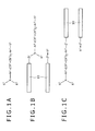
- FIGS. 1A to 1C individually illustrate labeled compounds according to embodiments of the invention.
- FIG. 1A shows the chemical structure of a labeled compound wherein S 1 or S 2 is a molecular chain-bound group in which a molecular chain capable of binding with a biomolecule is bound or is a reactive group capable of covalently bonding with a reactive group of a biomolecule.
- FIG. 1B is the chemical structure of a labeled compound (probe) wherein S 1 is a molecular chain-bound group whose molecular chain 10 capable of binding with a biomolecule is bound to a spacer (linker) Z 1
- FIG. 1C is the chemical structure of a labeled compound (probe) wherein S 2 is a molecular chain-bound group whose molecular chain 10 capable of binding with a biomolecule is bound to a spacer (linker) Z 2 .
- n is 0 or 1
- one of S 1 or S 2 is a molecular chain-bound group which has a molecular chain capable of binding with a biomolecule bound to a divalent spacer containing an alkyl group that may contain a divalent group selected from the following Gp1 at a main chain portion thereof, or which has a reactive group selected from the following Gp3, and the other of S 1 and S 2 is a group selected from the following Gp2.
- R 1 and R 2 may be the same or different and represent a group selected from a hydro group, an alkyl group and aryl group that may contain a hetero atom
- R 3 is a group selected from a hydro group, an alkyl group that may have a substituent group selected from the following Gp2, an aryl group that may has a substituent group, and a vinyl group that may have a substituent group.
- Ar 1 and Ar 2 represent a divalent group and may be the same or different and particularly represent an arylene group or a vinylene group wherein Ar 2 has at least one substituent group selected from an alkyl group, an aryl group, a cyano group (-CN), a tri fluoromethyl group (-CF 3 ) and a halo group, and when n is at 1, Ar 1 and R 1 or/and Ar 2 and R 2 may join together to form a ring.
- R 3 is a phenyl group (-C 6 H 5 ) or a naphthyl group (-C 10 H 7 )
- Ar 1 is a phenylene group (-C 6 H 4 -) or a naphthylene group (-C 10 H 6 -)
- Ar 2 is any of a phenylene group, a naphthylene group, an anthrylene group (-C 14 H 8 -) and a phenanthrene group (-C 14 H 10 -)
- R 1 and R 2 are individually a hydro group (-H).
- Gp1 is an arylene group, a vinylene group or a carbonyl
- Gp2 is a hydro group, an alkyl group or a vinyl group.
- Gp3 is a monovalent group and includes an N-hydroxysuccinimide ester group, a hydroxysulfosuccinimide ester group, an imide ester group, an isothiocyanate group, an isocyanate group, a maleimide group, a carboxyl group, an aldehyde group, a glyoxal group, an imidoester group, an oxirane group (an epoxy group, a glycidyl ether group), a triazine group, a carbodiimide group, an aziridine group, a halogenated acyl group, a halogenated alkyl group, a halogenated sulfonyl group or a vinylsulfone group.
- Gp3 is an N-hydroxysuccinimide ester group or a maleimide group.
- the labeled compound shown in FIG. 1B is a fluorescent probe wherein in the labeled compound of FIG. 1A , -S 1 is replaced by -Z 1 - (a molecular chain 10 capable of binding with a biomolecule).
- Z 1 is a divalent spacer (linker) containing an alkyl chain, which may contain a divalent group selected from the Gp1, at a main chain thereof.
- the labeled compound shown in FIG. 1C is a fluorescent probe wherein -S 2 in the labeled compound of FIG. 1A is replaced by -Z 2 - (a molecular chain 10 capable of binding with a biomolecule).
- Z 2 is a divalent spacer (linker) containing an alkyl chain, which may contain a divalent group selected from the Gp1, at a main chain thereof.
- the fluorescent probes are, respectively, made of an aromatic tertiary amine compound having the molecular chain capable of binding with a biomolecule bonded thereto and the molecular chain 10 capable of binding with the biomolecule is bound to the linker group Z 1 or Z 2 .
- the molecular chain 10 which is bondable with a biomolecule, is made, for example, of a nucleotide having a length of not smaller than 5 mer and larger than 40 mer.
- a biomolecule should inherently have a reactive group B capable of binding with the reactive group A or should be introduced with the reactive group B thereinto.
- the labeled compound has the reactive group A that is necessary for binding with a biomolecule serving as a sample, e.g. a protein or a nucleic acid, for which if the biomolecule is so designed that it inherently has or is preliminarily imparted with the reactive group B capable of reaction with the reactive group A, the biomolecule and the labeled compound form a covalent bond therebetween according to a known technique and bind together.
- Possible combinations of the reactive group A and the reactive group B capable of forming the covalent bond include, for example, amino group/carboxyl group, amino group/halogenated acyl group, amino group/N-hydroxysuccinimide ester group, amino group/aldehyde group, mercapto group/maleimide group, mercapto group/vinyl sulfonate group, hydroxyl group/carboxyl group and the like.
- Preferable combinations of the reactive group B and reactive group A include amino group/N-hydroxysuccinimide ester group and mercapto group/maleimide group.
- FIGS. 2 and 3 show examples of an aromatic amine fluorescent probe (first fluorescent probe) embodying the invention.
- the first fluorescent probes shown at the left side of FIG. 2 correspond to the labeled compound of FIG. 1B .
- n is 1, and S 2 contains a phenyl group to which an oxy group is bound wherein an oligonucleotide (oligo) is indirectly bound to the oxy group
- R 3 is a phenyl group or a naphthyl group
- Ar 1 is a phenylene group
- Ar 2 is a structure of any of a phenylene group, a naphthylene group, an anthrylene group and a phenanthrylene group which is unsubstituted or has a substituent group S 1 wherein S 1 is a methyl group or/and a cyano group.
- R 1 and R 2 are individually a hydro group.
- the first fluorescent probes shown at the right side of FIG. 2 correspond to the labeled compound shown in FIG. 1C .
- n is 1, and S 2 contains a phenyl group to which an oxy group is bound, R 3 is a phenyl group or a naphthyl group, and Ar 1 is a phenylene group.
- Ar 2 is a structure of any of a phenylene group, a naphthylene group, an anthrylene group and a phenanthrylene group, which is unsubstituted or has a cyano group as a substituent group and has a divalent group -CH 2 O- (oxymethylene group) or an oxy group to which an oligonucleotide (depicted as oligo) is indirectly bound.
- R 1 and R 2 are individually a hydro group.
- the first fluorescent probes shown in FIG. 3 correspond to the labeled compound of FIG. 1B .
- n is 1
- S 2 contains a phenyl group to which an oxy group is bound wherein an oligonucleotide (oligo) is bound indirectly to the oxy group.
- R 3 is a phenyl group or a naphthyl group
- Ar 1 is a phenylene group.
- Ar 2 is a structure of any of a phenylene group, a naphthylene group, an anthrylene group and a phenanthrylene group, which is unsubstituted or has a cyano substituent group.
- R 1 and R 2 are individually a hydro group.
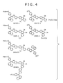
- FIG. 4 shows examples of an aromatic amine fluorescent probe (second fluorescent probe) embodying the invention.
- the two second fluorescent probes indicated at the upper portion of the left side of FIG. 4 correspond to the label compound of FIG. 1B .
- This second fluorescent probe is such that n is 0, S 2 contains a phenyl group to which an oxy group is bound and an oligonucleotide (oligo) is bound indirectly to the oxy group.
- R 3 is a naphtyl group
- Ar 1 is a naphthylene group
- Ar 2 is an anthrylene group or a phenanthrylene group having a substituent group S 1 wherein S 1 is a methyl group or/and a cyano group.
- the two second fluorescent probes indicated at the upper portion of the right side of FIG. 4 correspond to the labeled compound shown in FIG. 1C .
- This second fluorescent probe is such that n is 0, S 2 contains a phenyl group to which an oxy group is bound.
- R 3 is a naphtyl group
- Ar 1 is a naphthylene group
- Ar 2 is an anthrylene group or a phenanthrylene group which has a cyano group as a substituent group and also has a divalent group -CH 2 O- (oxymethylene group whose oxy group is indirectly bound to an oligonucleotide (oligo) or an oxy group.
- the two second fluorescent probes indicated at the lower portion of the left side of FIG. 4 correspond to the labeled compound shown in FIG. 1B .
- This second fluorescent probe is such that n is 0, S 2 contains a phenyl group to which an oxy group is bound wherein an oligonucleotide (oligo) is bound indirectly to the oxy group.
- R 3 is a naphtyl group
- Ar 1 is a naphthylene group
- Ar 2 is an anthrylene group or a phenanthrylene group which has a cyano group as a substituent group and is bound with a naphthyl group of an aromatic tertiary amine compound having a phenyl group and a naphthyl group bound to amino N.
- R 36 to R 51 individually represent a substituent group selected from a hydro group, an alkyl group, an aryl group, a vinyl group that may contain a substituent group, an amino group, a mercapto group (thiole group), a hydroxy group, a carbamoyl group, a sulfino group, a sulfo group, a carboxy group and a halo group.
- Ar 1 in the general formula (1) is a phenylene group
- R 3 is a phenyl group or a naphthyl group
- R 1 and R 2 are individually a hydro group
- Ar 2 is a phenylene group, a naphthylene group, a phenanthrylene group or an anthrylene group.
- Ar 3 in the general formula (2) is a naphthylene group
- R 4 is a naphthyl group
- Ar 4 is a phenanthrylene group or an anthrylene group.
- oligo means an oligonucleotide that is a molecular chain bondable with a biomolecule and this oligo is bound to S 1 or S 2 of the aromatic amine compound at the 5' or 3' terminal thereof.
- the third phenyl group of the triphenylamine moiety may be substituted with a naphthyl group (-C 10 H 7 ), which may be regarded as a triphenylamine derivative and is thus called triphenylamine moiety, like the former cases.
- the fluorescent probes are provided with structures having B, N, A and P explained hereinbelow and bound to the above-mentioned vinylene group.
- N indicates a naphthyl group (-C 10 H 7 ) having a substituent group
- A indicates an anthryl group (-C 14 H 9 ) that may have a substituent group
- P indicates a phenanthryl group (-C 14 H 9 ) having a substituent group.
- the aromatic amine fluorescent probes shown in FIG. 4 are made of tertiary amine compounds, which have such structures that in the triphenylamine moiety ((C 6 H 5 ) 3 N), one hydro group (-H) of the first phenyl group is substituted with an oxy group (-O-), the second phenyl group is substituted with a naphtyl group (-C 10 H 7 ), and the third phenyl group is substituted with a naphthylene group (-C 10 H 6 -) and to which a molecular chain (oligonucleotide, abbreviated as oligo in the figure) capable of binding with a biomolecule is added or (bound).
- oligonucleotide abbreviated as oligo in the figure
- the fluorescent probe having an anthrylene group bound to the naphthylene group of the tertiary amine compound is indicated as ANNPA and the fluorescent probe having a phenanthrylene group bound to the naphthylene group of the tertiary amine compound is indicated as DNPA.
- an alkyl group is bound to the oxy group or oxymethylene group (-CH 2 O-) with which the hydro group of the benzene ring is substituted, or the oxymethylene group (-CH 2 O-) with which the hydro group of the naphthalene ring is substituted, or the oxymethylene group (-CH 2 O-) with which the hydro group of the anthracene ring is substituted, or the oxy group with which the hydro group of the phenanthrene ring is substituted, to which the oligo is bound.
- FIG. 5 is a view showing an example of an aromatic amine fluorescent probe embodying the invention and more specifically, is a view illustrating a 3'-amino-5'-SP-1-oligonucleotide probe.
- the fluorescent probe of FIG. 5 has such a structure as shown in FIG. 1A and corresponds to SP-1 shown in FIG. 2 wherein the molecular chain 10 capable of binding with a biomolecule is bound to an aromatic tertiary amine compound. This probe corresponds to A17 appearing hereinafter in FIG. 10 .
- This molecular chain 10 contains an oligonucleotide made of an n number of nucleotides and this oligonucleotide consists of bonded nucleotides (which may be analogue nucleotides) having a base selected from A, T, G and C.
- N 2, 3, ..., (n-1)
- base N 2, 3, ..., (n-1)
- the oligonucleotide has -(PO 4 -)(CH 2 ) 6 NH- at the 5' terminal and -(PO 4- )(CH 2 ) 12 (PO 4- )(CH 2 )CH(CH 2 OH)(CH 2 ) 4 NH 2 at the 3' terminal.
- the NH- at the 5' terminal side of the oligonucleotide of the molecular chain 10 is bound to the aromatic tertiary amine compound SP-1 and the 3' terminal side is terminated with NH 2 .
- S 1 , Ar 2 , Ar 1 , R 3 and S 2 in the formula of FIG. 1A are, respectively, such that (Ar 2 -S1) is -C 19 H 6 (CN) 2 CH 3 , Ar 1 is -C 6 H 4 -, R 3 is -C 10 H 7 , and S 2 is -C 6 H 4 O(CH 2 ) 4 CO-.
- FIG. 6 shows an aromatic amine fluorescent probe according to an embodiment of the invention, particularly, a 5'-DNPA-oligonucleotide probe.
- the fluorescent probe shown in FIG. 6 has such a structure as shown in FIG. 1D wherein the molecular chain 10 capable of binding with a biomolecule is bound to an aromatic amine compound (DNPA-2, shown in FIG. 4 , provided that -OR 43 is replaced by -H).
- DNPA-2 aromatic amine compound
- This molecular chain 10 contains an oligonucleotide consisting of an n number of nucleotides as with the case of FIG. 5 .
- the oligonucleotide has (PO 4- ) (CH 2 ) 6 NH- at the 5' terminal and -OH at the 3' terminal.
- the NH- at the 5' terminal side of the oligonucleotide of the molecular chain 10 is bound to the DNPA-2 of the aromatic amine compound and the 3' terminal side is terminated with OH.
- S 4 , R 4 , Ar 3 , Ar 4 and S 3 shown in FIG. 1D are such that S 4 is -C 6 H 5 , R 4 is -C 10 H 7 , Ar 3 is -C 10 H 6 -, Ar 4 is -C 14 H 6 (CN) 2 -, and S 3 is -CO(CH 2 ) 4 CO-.
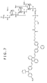
- FIG. 7 shows an example of an aromatic amine fluorescent probe embodying the invention, particularly, a 3'-BSA-2-5'-thio-oligonucleotide probe.
- the aromatic amine compound BSA-2 has a structure wherein -(C 6 H 4 )N(C 6 H 5 ) (C 6 H 4 )- is bound to the anthrylene group (-C 14 H 8 -) at opposite ends thereof.
- This molecular chain 10 contains an oligonucleotide consisting of an n number of oligonucleotides as with the case of FIG. 5 .
- the oligonucleotide has (PO 4- ) (CH 2 ) 12 (PO 4- ) (CH 2 )CH(CH 2 OH) (CH 2 ) 4 NH- at the 3' terminal and -(PO 4- ) (CH 2 ) 6 SH- at the 5' terminal.
- the NH- at the 3' terminal side of the oligonucleotide of the molecular chain 10 is bound to the BSA-2 of the aromatic amine compound and the 5' terminal side is terminated with SH.
- S 1 , Ar 2 , Ar 1 , R 3 and S 2 shown in FIG. 1A are such that S 1 is -CHCHC 6 H 4 N(C 6 H 5 ) (C 6 H 4 OCH 3 ), Ar 2 is -C 14 H 8 -, Ar 1 is -C 6 H 4 -, R 3 is -C 6 H 5 - and S 2 is -C 6 H 4 (CH 2 ) 4 CONH-.
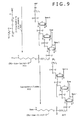
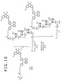
- FIGS. 8 , 9 and 10 are, respectively, a view showing an example of a synthetic scheme of an aromatic amine fluorescent probe embodying the invention and illustrate a synthetic scheme of a 3'-amino-5'-SP-1-oligonucleotide probe.
- FIG. 9 is a view subsequent to the synthetic scheme of FIG. 8 and
- FIG. 10 is a view subsequent to the synthetic scheme of FIG. 9 .
- the following reactions are generally carried out by use of a DNA solid phase synthetic apparatus.
- reaction ⁇ A1+A2 ⁇ A3 ⁇ indicates a 3'-amino-modifier C7 CPG (see FIG. 14A ), and A2 indicates a spacer phosphoramidite (Spacer C12 CE Phosphoramidite, made by Glen Research Corp.).
- reaction ⁇ A3+A4 ⁇ A5 ⁇ is carried out to permit the first nucleotide to be bound to A3.
- reaction ⁇ A5+A6 ⁇ A7 ⁇ is carried out thereby binding the second nucleotide to A5 in the same manner as set out above.
- a similar reaction ⁇ A7+A8 ⁇ A9 ⁇ is repeatedly carried out to permit binding nucleotides up to a desired nth nucleotide on the order of desired base species.
- reaction ⁇ A9+A10 ⁇ A11 ⁇ is carried out.
- A9 is 5'-amino-modifier C6 (see FIG. 14D ).
- reaction ⁇ A11+A12 ⁇ A13 ⁇ is carried out to deprotect the 5'-amino to provide NH 2 at the 5' terminal.
- reaction ⁇ A13+A14 ⁇ A15 ⁇ is carried out to bind A13 with SP-1-OSu (intermediate (activated esterified compound), see FIGS. 14 and 15 ).
- reaction ⁇ A15+A16 ⁇ A17 ⁇ is carried out to deprotect the 3' amino group and separate from CPG, thereby obtaining A17, i.e. a 3'-amino-5'-Sp1-oligoncleotide probe shown in FIG. 5 wherein SP-1 is bound to the 5' terminal and the 3' side is terminated with NH 2 .
- N-hydroxysuccinimide (C 9 H 5 NO 3 ) is represented by HOSu and -C 4 H 4 NO 3 is represented by -OSu herein and whenever they appear hereinafter in the ensuing figures.
- FIGS. 11 and 12 are a view showing an example of a synthetic scheme of an aromatic amine fluorescent probe according to an embodiment of the invention and illustrate a synthetic scheme of 3'-BSA-2-5'-thio-oligonucleotide probe.
- FIG. 12 shows the steps subsequent to the synthetic scheme of FIG. 11 .
- reaction (B1+B2 ⁇ B3) is carried out.
- B1 is same as A9 obtained in FIG. 8
- B2 is 5'-amino-modifier C6 (see FIG. 14C ).
- reaction ⁇ B3+B4 ⁇ B5) is carried out.
- the 3'-amino is deprotected and separated from CPG, thereby obtaining B5 wherein ST (T is a triphenylmethyl group) is bound to the 5' terminal and NH 2 is at the 3' terminal.
- reaction ⁇ B7+B8 ⁇ B9 ⁇ is carried out and the 5'-thiole is subjected to oxidative deprotection to obtain B9, i.e. 3'-BSA-2-5'-thio-oligonucleotide probe shown in FIG. 7 , wherein the 5' terminal group is SH and BSA-2 is bound to the 3' terminal.
- Examples of the solid phase support and reagent useful in FIGS. 8 to 12 are, respectively, those made by Glen Research Corporation and particularly shown in FIGS. 13A to 13D and also in FIGS. 14A to 14D .
- FIGS. 13A to 13D illustrate examples of the solid phase support used in the synthesis of the oligonucleotide probes according to the invention.
- oligonucleotide As shown in FIGS. 13A to 13D , compounds required for the synthesis of an oligonucleotide are available in the form supported on a polystyrene microbead or CPG.
- a nucleotide having an arbitrary one of A, T, G and C can be provided as the first nucleotide of an oligonucleotide.
- a nucleotide having a specified one of A, T, G and C can be provided as the first nucleotide of an oligonucleotide.
- CPG to which Icaa is bound is not shown.
- CPG controlled porous glass indicates a porous glass bead
- Me indicates a methyl group
- protected base means a base protected with a protective group
- DMT indicates a dimethoxytrityl group
- Icaa indicates a long-chain alkylamino group.
- FIGS. 14A to 14D illustrate examples of a solid phase support and a reagent used in the synthesis of oligonucleotide probes.
- FIGS. 14A and 14B show examples of a solid phase support and the supports of FIGS. 14A and 14B are used for amino modification at 3' terminal side.
- FIGS. 14C and 14D show examples of a reagent, and the reagent of FIG. 14C is for thiole modification at the 5' terminal side and FIG. 14D is used for amino modification at the 5' terminal side.
- Fmoc indicates a 9-fluorenylmethoxy group
- DMT indicates a dimethoxytrityl group
- Icaa indicates a long-chain alkylamino group
- CPG indicates a porous glass bead
- Pri indicates an isopropyl group
- ST indicates an S-trityl group
- MMT indicates a monomethoxytrityl group.
- the oligonucleotide probe is synthesized through preparation of an oligonucleotide using a solid phase support, preparation of intermediate compounds such as BSA-2-OSu, SP-1-OSu and the like and binding reaction between the thus prepared two molecules.
- SP-1-OSu is taken as an example of an intermediate compound and the synthetic process and the results thereof are illustrated, and synthesis of 3'-amino-5'-SP-1-oligonuclueotide probe is described.
- FIG. 15 is a view illustrating an intermediate SP-1-OSu used for the synthesis of an oligonucleotide probe (i.e. 3'-amino-5'-SP-1-oligonucleotide probe) in an example of the invention.
- an oligonucleotide probe i.e. 3'-amino-5'-SP-1-oligonucleotide probe
- a 10% sodium hydroxide aqueous solution (4.16 mmols) was added to 20 ml of a THF solution of 0.98 g (1.39 mmols) of compound 9 and stirred for 1 hour at 50°C. Further, 20 ml of THF, 4 ml of ethanol and a 10% sodium hydroxide aqueous solution (11.1 mmols) were added to the solution and stirred for 3 hours at 60°C. Precipitated crystals were separated by filtration and washed with THF. THF and hydrochloric acid were added to the resulting solid for dissolution, followed by removal of an insoluble material by filtration. The filtrate was concentrated under reduced pressure to obtain 0.69 g (yield of 73%) of dark brown crystalline compound 10.
- This compound 10 is a tertiary amine compound SP-1 (more accurately, an aromatic tertiary amine compound prior to binding with the molecular chain oligo (oligonucleotide) in the fluorescent probe SP-1 shown in FIG. 2 ).
- the intermediate SP-1-OSu can be synthesized according to reaction ⁇ (tertiary amine compound SP-1) + HOSu ⁇ SP-1-OSu + H 2 O ⁇ . More accurately, in the fluorescent probe SP-1 shown in FIG. 2 , when the tertiary amine compound prior to binding with the molecular chain oligo (oligonucleotide) is taken as Dy-OH, the intermediate compound Dy-OSu can be synthesized according to reaction ⁇ (Dy-OH) + HOSu ⁇ Dy-OSu + H 2 O ⁇ .
- B6 used in FIG. 12 i.e. BSA-2-OSu
- the aromatic tertiary amine compound prior to binding with the molecular chain oligo is indicated as Dy-OR and R is -H or an alkyl group, e.g. -CH 3
- the intermediate compound Dy-OSu can be synthesized according to reaction ⁇ (Dy-OR)+HOSu ⁇ Dy-OSu+ROH ⁇ .
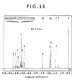
- FIG. 16 is a 1 H-NMR (nuclear magnetic resonance) spectral chart of the intermediate SP-1-OSu prepared in the example of the invention.
- the horizontal axis indicates a chemical shift (ppm) and the vertical axis indicates a nuclear magnetic resonance signal intensity.
- the chemical shift values at the respective signal peaks are indicated above the peaks, and signal integration is indicated in the vicinity of the signal peaks. It will be noted that NMR spectra were measured by use of NMR instrument, Model Number JNM-AL400 FT, made by JEOL Ltd.
- FIG. 17 is an MS spectral chart of intermediate SP-1-OSu prepared in the example of the invention.
- the MS spectra shown in FIG.17 are ones that are measured by use of MALDI-TOF-MS (matrix assisted laser desorption ionization-time of flight-mass spectrometer) and the instrument used for the measurement was Model KRATOS AXIMA-CFR, made by Shimadzu Corporation.
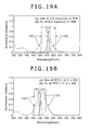
- the absorption and emission characteristics of the synthesized intermediate compound SP-1-OSu are illustrated.
- the absorption spectra and emission spectra were, respectively, measured by use of spectrophotometer Model U-3310 and fluorophotometer Model FL-4500, both made by Hitachi Ltd.
- FIGS. 18A and 18B are absorption and fluorescence spectral charts of intermediate SP-1-OSu under different measuring conditions, respectively, wherein FIG. 18A is a spectral chart in the state of a solution and FIG. 18B is a spectral chart in a dried state.
- the horizontal axis indicates a wavelength(nm) and the vertical axis indicates a relative intensity in case where maximal values of absorption and fluorescence spectra are normalized, taken as 1.0.
- the absorption maximum of a solution of the intermediate SP-1-OSu in a 10% EtOH:5xSSC buffer used as a solvent was at 474 nm with a molar absorption coefficient being at 120,000 M -1 cm -1 .
- the fluorescent maximum was at 650 nm and the fluorescence yield was at 0.0081.
- the Stokes shift obtained from the peaks of the absorption and fluorescence spectra was at 176 nm.
- An epoxy resin SU-8 (SU-8-3035-N-02, made by Kayaku Microchem Co., Ltd.) was diluted to 50% by use of cyclopentanone and spin coated (first at 500 rpm for 15 second and second at 1500 rpm for 30 seconds) onto an ozone-treated glass substrate, followed by drying at 100°C for 2 minutes.
- the epoxy resin was photocured by UV irradiation with a 50 mW/cm 2 xenon lamp for 6 seconds and annealed at 150°C for 10 minutes.
- the epoxy resin-bearing substrate was heated along with 3-aminopropyltriethoxysilane in an oven of 120°C and the amino group was introduced into the substrate.
- SP-1-OSu was dissolved in DMF at a concentration of 10 mM, in which the amino group-bearing substrate was immersed for 2 hours to cause the SP-1-OSu to be supported on the substrate.
- the excitation peak of the SP-1-OSu layer on the substrate in dry state was at 484 nm.
- the emission peak was at 556 nm.
- the Stokes shift calculated from the peaks of the absorption and fluorescence spectra was 72 nm.
- the intermediate SP-1-OSu exhibited large Stokes shifts in either a solution or a dry state.
- a dye enables us to design an excitation filter, which has an optically-transparent wavelength region fitting an absorption peak of the dye but not overlapping with the fluorescent spectrum of it. And thus, it maximizes the excitation efficiency.
- the dye enables us to design an emission filter, which has an optically-transparent wavelength region fitting a fluorescent peak of the dye but not overlapping with the absorption spectrum of it. And thus, it maximizes the fluorescent intensity. More particularly, the optically-transparent wavelength region of the excitation filter and the optically-transparent wavelength region of the fluorescent filter can be significantly separated from each other, and thus, it becomes easy to cut off stray light from emission of sample.
- FIGS. 19A and 19B are individually an absorption and fluorescence spectral chart for comparison wherein FIG. 19A is a spectral chart relating to IC3-OSu (Cy3) measured in a 5xSSC buffer and FIG. 19B is a spectral chart relating to FITC-I measured in a THF solution.
- FIG. 19A is a spectral chart relating to IC3-OSu (Cy3) measured in a 5xSSC buffer
- FIG. 19B is a spectral chart relating to FITC-I measured in a THF solution.
- FIGS. 19A and 19B (a) indicates an excitation spectrum and an excitation filter and (b) indicates a fluorescence spectrum and a fluorescence filter.
- the excitation filter and fluorescence filter have such wavelength transmission regions that are so close to each other.
- the transmittance data of the excitation filter and fluorescence filter are those laid open by Semrock Co., Ltd.
- IC3-OSu (Cy3) is a labeling agent of Dojindo Laboratories and is similar to Cy3, made by GE Healthcare Bioscience KK.
- FITC-I is one wherein an isothiocyanate group is bound to fluorescein.
- IC3-OSu has a Stokes shift of about 10 nm and as shown in FIG. 19B , FITC-I has a Stokes shift of about 25 nm.
- the intermediate SP-1-OSu has a Stokes shift much greater than those of IC3-OSu and FITC-I either in dry state or in solution.
- Cy3 and derivatives of fluorescein readily suffer degradation, for example, by application of a laser or a high-power light source, making reproducible repeated measurements difficult.
- SP-1 does not undergo such degradation and is usable in reproducible, repeated measurements.
- the dye Cy3 having two olefinic (ethylenic) double bonds and represented by the molecular formula C 25 H 26 N 2 Cl i.e. a dye of the above-mentioned formula (a) wherein the N + -C 10 H 14 O 4 N portion is changed to N-CH 3 and the NC 2 H 5 portion is changed to N-CH 3
- the dye SP represented by the molecular formula C 42 H 29 N 3 i.e. a dye of the chemical formula 8 indicated in FIG. 15 having a structure wherein -OH is changed to -CH 3
- the dye Cy3 and dye SP were, respectively, according to the molecular orbital calculation, subjected to structural optimization of the ground state and energy levels of HOMO (highest occupied molecular orbital) and LUMO (lowest occupied molecular orbital) in the ground state were determined. Next, one electron was removed from HOMO of the ground state, then it was put onto LUMO with spin-flipping. After the structural re-optimization in which modified LUMO was regarded as the initial excited state, the energy levels of HOMO and LUMO were calculated. In addition, structural changes in the ground and excited states were checked.
- the energy levels of HOMO in the ground state and LUMO in the excited state calculated according to the molecular orbital calculation were, respectively, at 6.26 eV and 2.56 eV, and the Stokes shift which is a gap between those levels was at 3.7 eV.
- the energy levels of HOMO in the ground state and LUMO in the excited state calculated according to the molecular orbital calculation were, respectively, at 7.22 eV and 2.39 eV, and the Stokes shift was at 4.83 eV.
- the Stokes shift of the dye SP is greater than the Stokes shift of the dye Cy3.
- the structural change of the dye SP associated with excitation, or the structural change in the ground and excited states, is observed: (1) in the difference of a twisted angle around the olefinic (ethylenic) double bond connecting the phenanthrene ring and the phenyl ring as viewed from the upper face of the phenanthrene ring, (2) in the difference of an angle around the amine nitrogen (N) as viewed from the axial direction of the above-mentioned olefinic double bond, (3) in the difference of an angle between the planes, respectively, made by the phenanthrene ring and the phenyl ring (a ring located between the amine nitrogen(N) and the olefinic double bond) and the difference in planarity of the phenanthrene ring, i.e. a difference in positional relation of the plane made by the phenanthrene relative to the plane made by the phenyl ring.
- the labeled compound according to the invention has one or two amine moiety (e.g. an amine moiety where a phenyl ring or a naphthyl ring is bound to amine nitrogen, or an electro-donating site) bound to a cyano-arene (e.g. an phenanthrene ring substituted with cyano group(s), or an electro-withdrawing site) through the olefinic (ethylenic) double bond of the styryl moiety.
- a cyano-arene e.g. an phenanthrene ring substituted with cyano group(s), or an electro-withdrawing site
- red shift occurs both in the absorption and the fluorescence.
- PMT photomultiplier tube
- the labeled compound of the invention is larger in Stokes shift and higher in light resistance than existing labeled compounds. Accordingly, the optically-transparent wavelength region of an excitation filter and an optically-transparent wavelength region of a fluorescence filter can be satisfactorily separated from each other. Therefore, a fluorescence emitted from a sample can be separated from other unnecessary stray light and the like. A sample molecule can be detected at high sensitivity and at a high SN ratio.
- the compound is excellent in light resistance, for which if an intensity of excitation light is increased for detection of trace amounts of molecules, a data variation due to photodegradation of a labeled compound is scarcely experienced. Thus, stable repetitions of measurement are possible and reproducibility of repeated measurements can be improved.
- the intermediate SP-1-OSu is the compound used in the synthetic scheme (see FIGS. 8 to 10 ) of the 3'-amino-5'-SP-1-oligonucleotide probe.
- This intermediate SP-1-O-Su may be used as a compound capable of covalent bonding with a biomolecule, i.e. a fluorescently-labeled compound.
- the intermediate SP-1-OSu is an ester having an active-esterified carbonyl group (an N-hydroxysuccinimide ester group (called an NHS group or an OSu group)), which covalently binds with an amino group of an amino acid or protein. Accordingly, the intermediate SP-1-OSu can be used as a fluorescently-labeled compound.
- SP-1-OSu is bound to a biomolecule having an amino group such as of an amino acid or a protein and is thus labeled, and allows a fluorescence to be generated through photoexcitation.
- a biomolecule can be detected and the intermediate can be used as a fluorescent labeling compound for biomolecules.
- the labeled compound of the invention can be bound to an antigen molecule, a ligand molecule and a sugar protein, respectively, and an antibody molecule, a receptor molecule and a lectin molecule bound to the former molecules, respectively, can be detected.
- the invention provides a labeled compound capable of detecting a living body-derived molecule at high sensitivity at a high SN ratio.
Abstract


Description
- This invention relates to a labeled compound used for detection of a sample molecule and more particularly, to a labeled compound designed to permit an aromatic tertiary amine compound to be capable of binding with the sample molecule and also to a detection method using the same.
- There are known techniques of analyzing biomolecules wherein sample molecules made of various types of biomolecules such as of nucleic acids, proteins, sugars, enzymes, hormones, antigens, antibodies and the like are fluorescently labeled and the fluorescence is detected. This analyzing technique is a fundamental one in the fields of the analysis of life phenomena, genetic diagnosis, tissue engineering and the like and is also an essential one in the screening of medical drugs. For instance, labeling of gene, protein with a fluorescent dye enables a specific type of gene or protein in an analyte to be detected at high sensitivity.
- Comprehensive analyses of analytes have been conducted, for example, by labeling many types of oligonucleotides or peptides with fluorescent dyes and using DNA chips or protein chips fixing a microarray of the labeled oligonucleotides or peptides thereon. Moreover, in an immunostaining or molecule imaging technique wherein a specific type of biomolecule such as, for example, of a sugar, protein or the like is labeled with a fluorescent dye and is observed through a fluorescence microscope after generation of a fluorescence, dynamic analyses of an intracellular or intercellular molecule become possible.
- The labeled probe obtained by labeling DNA, a DNA base derivative, a DNA oligonucleotide or the like with a fluorescent dye is employed in northern blotting, Southern blotting, in situ hybridization, DNA sequence determination reaction and the like. The antibody or antigen labeled with a fluorescent dye is used for immunoassay making use of an antigen-antibody reaction. There is also known an enzyme immunoassay method to which the avidin (streptoavidin)-biotin linkage is applied and in which avidin modified with a fluorescent dye is used.
- For the labeling of a biomolecule serving as a sample to be detected, for example, an aromatic dye compound such as FITC (fluorescein isothiocyanate), TRITC (tetramethylrhodamine isothiocyanate), fluorescein, rhodamine, coumarin, cyanine dye or the like is used as the fluorescent labeling reagent.
- Techniques relating to the detection of biomolecules and various types of fluorescent labeling compounds used for the detection of biomolecules are known and reported as shown below.
- In Japanese Patent Laid-open No.
2005-208026 - The method for detecting a biomolecule in the
Patent Document 1 is characterized in that a biomolecule sample and an organic EL (electroluminescence) dye are reacted with each other and the fluorescence of the biomolecule sample labeled with the organic EL dye is measured. It is stated that the organic EL dye used is made of a compound containing a conjugated five-membered ring compound, for which there can be used a compound containing at least one hetero atom, selenium atom or boron atom. Moreover, there may be further used a condensed polycyclic compound made of a five-membered ring compound and a conjugated six-membered ring compound, wherein the five-membered ring compound used may be an azole derivative or an imidazole derivative. - Prior to the reaction with a biomolecule, the organic EL dye may be introduced thereinto with any one of functional groups selected from an isocyanate group, an epoxy group, a halogenated alkyl group, a triazine group, a carbodiimide group and an active-esterified carbonyl group.
- The labeling dye of the
Patent Document 1 is one used for detection of a biomolecule based on fluorescent measurement and is characterized in that it consists of an organic EL dye having a reactive group capable of binding to the biomolecule. It is stated that as the reactive group, there can be used any one of functional groups selected from a carboxylic group, an isocyanate group, an epoxy group, a halogenated alkyl group, a triazine group, a carbodiimide group and an active-esterified carbonyl group. - It is also stated in the
Patent Document 1 that the organic EL dye is a compound containing a conjugated five-membered ring compound and a compound containing at least one hetero atom, selenium atom or boron atom may be used as this five-membered ring compound. In addition, there may be further used a condensed polycyclic compound composed of the five-membered ring compound and a conjugated six-membered ring compound. The five-membered ring compound may be an azole derivative or an imidazole derivative. - A variety of organic EL dyes are known aside from those set out in the
Patent Document 1. For instance, there have been reported organic EL dyes composed of styryl compounds having a diversity of structures, for example, in Patent Documents indicated below: - Japanese Patent No.
3852517 - Japanese Patent No.
3852518 - Japanese Patent No.
3852520 - Japanese Patent No.
3555736 - Japanese Patent No.
3820752 - Japanese Patent Laid-open No.
2000-230132 - Japanese Patent Laid-open No.
2001-106657 - Japanese Patent Laid-open No.
2001-106658 - Japanese Patent Specification No.
3852552 - Japanese Patent Laid-open No.
2001-131128 - Japanese Patent Laid-open No.
2001-288377 - Japanese Patent Laid-open No.
2002-226722 - Japanese Patent Laid-open No.
2004-87463 - Japanese Patent No.
4001118 - Japanese Patent Laid-open No.
2005-5226 - Japanese Patent Laid-open No.
2005-35927 - Japanese Patent Laid-open No.
2006-124333 - Japanese Patent Laid-open No.
2006-128437 - Japanese Patent Laid-open No.
2006-273737 - Where the sample molecule labeled with a fluorescent dye, e.g. a biomolecule, is excited with excitation light and the fluorescence emitted from the fluorescent dye is detected with a photodetector to detect the biomolecule, the usual practice is to use a filter that is able to cut off light having wavelengths other than a desired wavelength region and pass a fluorescence within a desired wavelength region to a photodetector in order to intercept the incidence of the excitation light and other stray light into the photodetector. If the excitation light is not effectively cut off or intercepted by means of the filter, the excitation light not cut off with the filter causes stray light ascribed to the refraction and reflection in the light path for measuring fluorescence, thereby causing noises in the fluorescence detection.
- To reduce the noises in the fluorescent detection, it is desirable to excite a fluorescent dye with excitation light that is as weak as possible. For the detection of trace molecules, when the intensity of excitation light is increased for irradiation of a fluorescent dye so as to make a high fluorescence intensity and high sensitivity, noises simultaneously increases, resulting in the difficulty in improving the SN ratio. If a fluorescent dye is irradiated under an increased intensity of excitation light, some type of fluorescent dye that is not satisfactory in light resistance may undergo photodegradation.
- In general, the detection sensitivity of a sample molecule labeled with a fluorescent dye, e.g. a biomolecule, depends on the difference between the wavelength (excitation wavelength) of excitation light exciting the fluorescent dye and the wavelength (fluorescence wavelength) of the fluorescence emitted from the fluorescent dye (i.e. the Stokes shift). If the Stokes shift is greater or the difference between the excitation wavelength and the fluorescence wavelength is greater and if a fluorescence to be detected is in a wavelength region that is more distant from that of the excitation light, the rate of elimination of stray light with a filter becomes higher, resulting in more reduction of noises. Where the Stokes shift is small, the detection of a fluorescence from a fluorescent dye is significantly impeded owing to the background noises ascribed to scattered excitation light, or background noises which are derived from the fluorescence of a co-existing substance in a sample containing a sample molecule. Thus, high sensitive measurement becomes difficult.
- It is accordingly preferable to provide a labeled compound and a detection method using the compound, which overcome the problems involved in the related art techniques.
- It is further preferable to provide a labeled compound of the type which is so designed that an aromatic tertiary amine compound is enabled to be bound with a sample molecule and the sample molecule can be detected at high sensitivity and at a high SN ratio, and also to a detection method using such a labeled compound as mentioned above.
- According to one embodiment of the invention, there is provided a labeled compound designed to enable an aromatic tertiary amine compound represented by the following general formula (1) to be bound with a sample molecule:

- According to another embodiment of the invention, there is also provided a detection method of a sample molecule using such a labeled compound as set forth above, the method including the steps of binding the above-defined labeled compound to a sample molecule, and detecting a fluorescence emitted from the labeled compound bound to the sample molecule by irradiation of light.
- According to the embodiments of the invention, there can be provided a labeled compound which has a skeletal structure ensuring a high Stokes shift and a high fluorescence yield and is able to detect a sample molecule at high sensitivity and a high SN ratio. This labeled compound is higher in light resistance when compared with existing labeled compounds. When an excitation light intensity is increased for detection of trace molecules by photoexcitation of the labeled compound, there is little data variation as would be caused by photodegradation of the labeled compound.
- According to the embodiments of the invention, there is also provided a detection method wherein a sample molecule can be detected at high sensitivity and a high SN ratio.
-
-
FIGS. 1A to 1C are views each illustrating an aromatic amine fluorescent probe embodying the invention; -
FIG. 2 is a view showing examples of an aromatic amine fluorescent probe (first fluorescent probe) embodying the invention; -
FIG. 3 is a view showing examples of an aromatic amine fluorescent probe (first fluorescent probe) embodying the invention; -
FIG. 4 is a view showing examples of an aromatic amine fluorescent probe (second fluorescent probe) embodying the invention; -
FIG. 5 is a view showing an example of an aromatic amine fluorescent probe and illustrating a 3'-amino-5'-SP-1-oligonucleotide probe embodying the invention; -
FIG. 6 is a view showing an example of an aromatic amine fluorescent probe and particularly illustrating a 5'-DNPA-oligonucleotide probe embodying the invention; -
FIG. 7 is a view showing an example of an aromatic amine fluorescent probe and particularly illustrating a 3'-BSA1-5'-thio-oligonucleotide probe embodying the invention; -
FIG. 8 is a view showing an example of a synthetic scheme of an aromatic amine fluorescent probe and particularly illustrating a synthetic scheme of 3'-amino-5'-SP-1-oligonucleotide probe embodying the invention; -
FIG. 9 is a view subsequent to the synthetic scheme ofFIG. 8 ; -
FIG. 10 is a view subsequent to the synthetic scheme ofFIG. 9 ; -
FIG. 11 is a view showing an example of a synthetic scheme of an aromatic amine fluorescent probe and particularly illustrating a synthetic scheme of 3'-BSA-2-5'-thio-oligonucleotide probe embodying the invention; -
FIG. 12 is a view subsequent to the synthetic scheme ofFIG. 11 ; -
FIGS. 13A to 13D are views each illustrating an example of a solid phase support used in the synthesis of an oligonucleotide probe embodying the invention; -
FIGS. 14A to 14D are examples of a solid phase support and reagents used in the synthesis of an oligonucleotide probe embodying the invention; -
FIG. 15 is a view illustrating absorption and fluorescence spectra of an intermediate SP-1-OSu employed in the synthesis of an oligonucleotide probe in an example of the invention; -
FIG. 16 is a chart of 1H-NMR spectra of the synthesized intermediate SP-1-OSu in the example of the invention; -
FIG. 17 is a chart of MS spectra of the synthesized intermediate SP-1-OSu in the example of the invention; -
FIGS. 18A and 18B are charts of absorption and fluorescence spectra of the synthesized intermediate SP-1-OSu in the example of the invention; and -
FIGS. 19A and 19B are charts of absorption and fluorescence spectra for comparison. - In the labeled compound of the invention, it is preferred that Ar1 is a phenyl group, Ar2 is any of a phenylene group, a naphthylene group, a phenanthrylene group and an anthrylene group, and R1 and R2 are individually a hydro group, by which the afore-indicated general formula (1) can be re-formulated as represented by the following general formula (2):

- In the formula (2), the compound is preferably so designed that S2 is the afore-indicated molecular chain-bound group. By this, the compound can be readily prepared from commercially available reagents by several steps.
- Further, it is preferred that the compound of the general formula (1) is so re-formulated as to provide a compound of the following general formula (3):

- In the formula (3), R4 and R5 may be the same or different and represent a group selected from a hydro group, an alkyl group that may has a substituent group and an aryl group that may have a substituent group.
- Moreover, it is also preferred that the compound of the general formula (2) is so re-formulated as to provide a compound of the following general formula (4):

- Further, it is also preferred that the compound of the general formula (3) is re-formulated as to provide a compound represented by the following general formula (5):

- Further, it is preferred that S1 represents such a molecular chain-bound group as defined before. In doing so, the hydrophobic fluorophore (a component of a molecule which causes a molecule to be fluorescent) can be kept remote from a hydrophilic biomolecule, so that the quenching process and chemical reaction ascribed to the interaction between the dye and the biomolecule can be reduced.
- Moreover, the compound of the general formula (3) can be so re-formulated or designed as to provide a compound represented by the following general formula (6):

- Preferably, the alkyl chain should have not smaller than 3 to not larger than 20 carbon atoms. This enables the distance between the hydrophobic fluorophore (fluorescent dye skeleton) and the hydrophilic biomolecule to be kept appropriately. Consequently, the quenching ascribed to the interaction between the dye and the biomolecule and the chemical reaction can be reduced. On the other hand, when the alkyl chain is too long, hydrophobicity undesirably increases for use as a labeled compound, with some possibility that interaction with a sample molecule is suppressed.
- The sample molecule should preferably be one derived from a living body. By this, the living body-derived molecule can be detected at high sensitivity and a high SN ratio and can be detected by repeated light irradiation or by long-term light irradiation as would be difficult because of the thus far experienced unsatisfactory durability of dyes against light.
- Moreover, the molecular chain should preferably be made up of an oligonucleotide. By this, the sample can be detected at high sensitivity and a high SN ratio as the result of the hybridization which is a double helix formation between the sample oligonucleotide and its complementary oligonucleotide strand bound to the labeled compound in the invention.
- This oligonucleotide should preferably have a length of not smaller than 5 mer to not larger than 40 mer. This permits stable complementary binding between the sample oligonucleotide and its complementary oligonucleotide bound to the compound.
- The oligonucleotide should preferably be so designed as to be used as a probe for detecting a complementary oligonucleotide strand of the living body-derived molecule having a complementary strand sequence thereof. This leads the complementary oligonucleotide strand to be detected at high sensitivity and a high SN ratio.
- Preferably, the Gp3 is an N-hydroxysuccinimide ester group so as to permit an amino group contained in a sample molecule to be bound. In doing so, the sample molecule containing an amino group can be detected at high sensitivity and a high SN ratio.
- Further, it is preferred that the Gp3 is preferably a maleimide group so as to permit a mercapto group contained in a sample molecule to be bound therewith. This allows the sample molecule containing a mercapto group to be detected at high sensitivity and a high SN ratio.
- R3 is preferably a phenyl group or a naphthyl group. In doing so, the bulkiness around the arylamino moiety can increase and thus, the quenching process derived from the interaction with other chemical substances co-existing in use can be reduced, with the result that there can be provided a compound having a high fluorescence yield.
- Ar1 is preferably a phenylene group or a naphthylene group. This permits ready synthesis from commercially available reagents by several steps. The bulkiness around the phenylamino moiety can increase, so that the quenching process ascribed to the interaction with other chemical substances co-existing in use can be reduced, thereby providing a compound having a high fluorescence yield.
- Ar2 is preferably one of a phenylene group, a naphthylene group, an anthrylene group and a phenanthlene group. In doing so, the resonance structure of a fluorophore (dye skeleton moiety) is stabilized and thus, a high fluorescence yield can be achieved.
- In the afore-indicated general formula (1), Ar1-(CR1=CR2)n-Ar2 (wherein n is 0 or 1) can be regarded as containing repeating units (C=C-) starting from the double bond of the Ar1 moiety through (CR1=CR2)n to the double bond of Ar2. In this sense, it is preferred that when the number of the repeating units is taken as m, such a structure of N-(C=C-)m (wherein m≥6) is established. By this, a maximum wavelength of a fluorescence created by the photoexcitation of the resulting labeled compound can be within a desired wavelength region and a great Stokes shift can be attained.
- The labeled compound according to an example of the invention is a fluorescently-labeled compound which is able to emit a fluorescence by photoexcitation and is so designed that an aromatic tertiary amine compound (which may be hereinafter called merely aromatic amine in some cases) is bondable with a biomolecule. The labeled compound contains either a molecular chain-bound group wherein a molecular chain (e.g. an oligonucleotide) capable of binding with a sample molecule, e.g. a biomolecule, or a reactive group (e.g. an N-hydroxysuccinimide ester or a maleimide group) capable of covalent bonding with a reactive group (e.g. an amino group or a mercapto group) present in a biomolecule. This molecular chain-bound group or reactive group is bound directly or indirectly to amino N (nitrogen).
- In the fluorescently-labeled compound according to the embodiment of the invention, the above-mentioned molecular chain is made up of an oligonucleotide, by which this oligonucleotide can be used as a probe for detecting a complementary oligonucleotide strand of a biomolecule having a complementary strand sequence, thereby enabling this complementary oligonucleotide strand to be detected at high sensitivity and a high SN ratio. In some cases, such a probe may be hereinafter referred to as an aromatic tertiary amine fluorescent probe (or abbreviated as an aromatic amine fluorescent probe or a fluorescent probe), or an oligonucleotide probe.
- Where the fluorescently-labeled compound according to the embodiment of the invention is made up of an aromatic tertiary amine compound that has a reactive group capable of binding with a sample molecule, e.g. a biomolecule, this aromatic tertiary amine compound has reactive group A capable of binding with the biomolecule. Reactive group B which the biomolecule inherently has or which has been preliminarily imparted to the biomolecule and the reactive group A of the fluorescently-labeled compound form a covalent bond, so that the fluorescently-labeled compound and the biomolecule bind together. The detection of a fluorescence emitted by excitation of the fluorescently-labeled compound bound to the biomolecule leads to the detection of the sample biomolecule at high sensitivity and a high SN ratio.
- The labeled compound according to the embodiment of the invention has any of a phenyl group or a naphthyl group bound to amino N, a phenylene group or a naphthylene group bound to amino N, and a phenylene group, a naphthylene group, an anthrylene group or a phenanthrene group bound directly or indirectly to the phenylene or naphthylene group bound to amino N. Ar1-(CR1=CR2)n-Ar2 (wherein n is 0 or 1) in the foregoing general formula (1) contains repeating units (C=C-) and has N-(C=C-)m wherein m≥6 when the number of the repeating units is taken as m.
- It will be noted that the molecular chain-bound group or the reactive group is bound to any of a phenyl group or a naphthyl group bonded to amino N and a phenylene group, a naphthylene group, an anthrylene group or a phenanthrene group directly or indirectly bound to the phenylene group or naphthylene group bound to amino N.
- Because of the presence of the repeated units (C=C-), the peak wavelength of a fluorescence resulting from the photoexcitation of the labeled compound can be within a desired wavelength region, the Stokes shift can be made great and satisfactory light resistance is ensured. The fluorescence emitted by excitation through photoirradiation of the labeled compound bound to the biomolecule is detected, thus enabling the target biomolecule to be detected at high sensitivity and a high SN ratio.
- With the fluorescent probe based on the labeled compound according to the embodiment of the invention or the detection method using the fluorescently-labeled compound covalently bonded to a sample molecule, the sample molecule (or target molecule) to be detected consists of a biomolecule such as a living body-derived molecule, a physiologically active molecule or the like, and such a biomolecule can be detected at high sensitivity and a high SN ratio.
- The biomolecule includes those, for example, of enzymes, proteins, sugars, nucleic acids, oligonucleotides, fats, amino acids and the like. The proteins include, for example, antibodies and derivatives thereof, antigens and derivatives thereof, avidins including streptoavidin, serum albumins, hates, hormones and the like. The invention is applicable to the detection of chemical substances such as diagnostic medicines, curing medicines and the like, environmental substances causing diseases such as allergies and the like.
- Embodiments of the invention are now described in detail with reference to the accompanying drawings.
-
FIGS. 1A to 1C individually illustrate labeled compounds according to embodiments of the invention.FIG. 1A shows the chemical structure of a labeled compound wherein S1 or S2 is a molecular chain-bound group in which a molecular chain capable of binding with a biomolecule is bound or is a reactive group capable of covalently bonding with a reactive group of a biomolecule.FIG. 1B is the chemical structure of a labeled compound (probe) wherein S1 is a molecular chain-bound group whosemolecular chain 10 capable of binding with a biomolecule is bound to a spacer (linker) Z1, andFIG. 1C is the chemical structure of a labeled compound (probe) wherein S2 is a molecular chain-bound group whosemolecular chain 10 capable of binding with a biomolecule is bound to a spacer (linker) Z2. - In the labeled compound shown in
FIG. 1A , n is 0 or 1, one of S1 or S2 is a molecular chain-bound group which has a molecular chain capable of binding with a biomolecule bound to a divalent spacer containing an alkyl group that may contain a divalent group selected from the following Gp1 at a main chain portion thereof, or which has a reactive group selected from the following Gp3, and the other of S1 and S2 is a group selected from the following Gp2. - In the formulas, R1 and R2 may be the same or different and represent a group selected from a hydro group, an alkyl group and aryl group that may contain a hetero atom, R3 is a group selected from a hydro group, an alkyl group that may have a substituent group selected from the following Gp2, an aryl group that may has a substituent group, and a vinyl group that may have a substituent group.
- Ar1 and Ar2 represent a divalent group and may be the same or different and particularly represent an arylene group or a vinylene group wherein Ar2 has at least one substituent group selected from an alkyl group, an aryl group, a cyano group (-CN), a tri fluoromethyl group (-CF3) and a halo group, and when n is at 1, Ar1 and R1 or/and Ar2 and R2 may join together to form a ring.
- For instance, R3 is a phenyl group (-C6H5) or a naphthyl group (-C10H7), Ar1 is a phenylene group (-C6H4-) or a naphthylene group (-C10H6-), Ar2 is any of a phenylene group, a naphthylene group, an anthrylene group (-C14H8-) and a phenanthrene group (-C14H10-), and R1 and R2 are individually a hydro group (-H).
- Gp1 is a divalent group and includes an arylene group that may contain a hetero atom (i.e. a group formed by withdrawing one hydrogen atom from an aryl group or a group formed by withdrawing one hydrogen atom from a monocyclic or polycyclic aromatic ring-bearing aromatic compound and heteroaromatic compound), a vinylene group (-CH=CH-), a carbonyl group -(CO-), an oxy group (-O-), an oxycarbonyl group (-O-CO-), a thio group (-S-), a sulfinyl group (-SO-), a sulfonyl group (-SO2-), an imino group (-NH-), a urylene group (-NHCONH-), an amide group (H2NC(O=NH)-) or a silylene group (-SiH2-). Preferably, Gp1 is an arylene group, a vinylene group or a carbonyl group.
- Gp2 is a monovalent group and includes a hydro group (-H), an alkyl group (-CnH2n+1), an aryl group, a vinyl group (-CH=CH2) that may contain a substituent group, an amino group (-NH2), a mercapto group (-SH), a hydroxy group (-OH), a carbamoyl group (H2NCO-), a sulfino group (-SO2H), a sulfo group (-SO3H), a carboxy group (-COOH) or a halo group (i.e. a halogen group such as -F, -Cl, -Br or -I). Preferably, Gp2 is a hydro group, an alkyl group or a vinyl group.
- Gp3 is a monovalent group and includes an N-hydroxysuccinimide ester group, a hydroxysulfosuccinimide ester group, an imide ester group, an isothiocyanate group, an isocyanate group, a maleimide group, a carboxyl group, an aldehyde group, a glyoxal group, an imidoester group, an oxirane group (an epoxy group, a glycidyl ether group), a triazine group, a carbodiimide group, an aziridine group, a halogenated acyl group, a halogenated alkyl group, a halogenated sulfonyl group or a vinylsulfone group. Preferably, Gp3 is an N-hydroxysuccinimide ester group or a maleimide group.
- The labeled compound shown in
FIG. 1B is a fluorescent probe wherein in the labeled compound ofFIG. 1A , -S1 is replaced by -Z1- (amolecular chain 10 capable of binding with a biomolecule). Z1 is a divalent spacer (linker) containing an alkyl chain, which may contain a divalent group selected from the Gp1, at a main chain thereof. - The labeled compound shown in
FIG. 1C is a fluorescent probe wherein -S2 in the labeled compound ofFIG. 1A is replaced by -Z2- (amolecular chain 10 capable of binding with a biomolecule). Z2 is a divalent spacer (linker) containing an alkyl chain, which may contain a divalent group selected from the Gp1, at a main chain thereof. - As will be seen from
FIGS. 1B and 1C , the fluorescent probes are, respectively, made of an aromatic tertiary amine compound having the molecular chain capable of binding with a biomolecule bonded thereto and themolecular chain 10 capable of binding with the biomolecule is bound to the linker group Z1 or Z2. - In the labeled compounds having such structures as shown in
FIGS. 1B and 1C , themolecular chain 10, which is bondable with a biomolecule, is made, for example, of a nucleotide having a length of not smaller than 5 mer and larger than 40 mer. - In the labeled compound shown in
FIG. 1A , where one of S1 and S2 contains a reactive group A, a biomolecule should inherently have a reactive group B capable of binding with the reactive group A or should be introduced with the reactive group B thereinto. The labeled compound has the reactive group A that is necessary for binding with a biomolecule serving as a sample, e.g. a protein or a nucleic acid, for which if the biomolecule is so designed that it inherently has or is preliminarily imparted with the reactive group B capable of reaction with the reactive group A, the biomolecule and the labeled compound form a covalent bond therebetween according to a known technique and bind together. - Possible combinations of the reactive group A and the reactive group B capable of forming the covalent bond include, for example, amino group/carboxyl group, amino group/halogenated acyl group, amino group/N-hydroxysuccinimide ester group, amino group/aldehyde group, mercapto group/maleimide group, mercapto group/vinyl sulfonate group, hydroxyl group/carboxyl group and the like. Preferable combinations of the reactive group B and reactive group A include amino group/N-hydroxysuccinimide ester group and mercapto group/maleimide group.
- The labeled compounds having such structures as shown in
FIGS. 1A to 1C are such that Ar1-(CR1=CR2)n-Ar2 wherein n is 0 or 1 has repeating units of (C=C-) and when the number of the repeating units is taken as m, the compound has N-(C=C-)m wherein m≥6. - The case where the labeled compound of
FIG. 1A is applied as a fluorescent probe as shown inFIGS. 1B or 1C is now described. -
FIGS. 2 and3 show examples of an aromatic amine fluorescent probe (first fluorescent probe) embodying the invention. - The first fluorescent probes shown at the left side of
FIG. 2 correspond to the labeled compound ofFIG. 1B . With this first fluorescent probe, n is 1, and S2 contains a phenyl group to which an oxy group is bound wherein an oligonucleotide (oligo) is indirectly bound to the oxy group, R3 is a phenyl group or a naphthyl group, Ar1 is a phenylene group, Ar2 is a structure of any of a phenylene group, a naphthylene group, an anthrylene group and a phenanthrylene group which is unsubstituted or has a substituent group S1 wherein S1 is a methyl group or/and a cyano group. R1 and R2 are individually a hydro group. - The first fluorescent probes shown at the right side of
FIG. 2 correspond to the labeled compound shown inFIG. 1C . With this first fluorescent probe, n is 1, and S2 contains a phenyl group to which an oxy group is bound, R3 is a phenyl group or a naphthyl group, and Ar1 is a phenylene group. Ar2 is a structure of any of a phenylene group, a naphthylene group, an anthrylene group and a phenanthrylene group, which is unsubstituted or has a cyano group as a substituent group and has a divalent group -CH2O- (oxymethylene group) or an oxy group to which an oligonucleotide (depicted as oligo) is indirectly bound. R1 and R2 are individually a hydro group. - The first fluorescent probes shown in
FIG. 3 correspond to the labeled compound ofFIG. 1B . With this first probe, n is 1, S2 contains a phenyl group to which an oxy group is bound wherein an oligonucleotide (oligo) is bound indirectly to the oxy group. R3 is a phenyl group or a naphthyl group, Ar1 is a phenylene group. Ar2 is a structure of any of a phenylene group, a naphthylene group, an anthrylene group and a phenanthrylene group, which is unsubstituted or has a cyano substituent group. In addition, Ar2 is bound with -CH=CH-, to which a phenyl group bound to amino N, or a phenyl group or an aromatic tertiary amine compound having a phenyl group and a naphthyl group is bound. R1 and R2 are individually a hydro group. -
FIG. 4 shows examples of an aromatic amine fluorescent probe (second fluorescent probe) embodying the invention. - The two second fluorescent probes indicated at the upper portion of the left side of
FIG. 4 correspond to the label compound ofFIG. 1B . This second fluorescent probe is such that n is 0, S2 contains a phenyl group to which an oxy group is bound and an oligonucleotide (oligo) is bound indirectly to the oxy group. Moreover, R3 is a naphtyl group, Ar1 is a naphthylene group, Ar2 is an anthrylene group or a phenanthrylene group having a substituent group S1 wherein S1 is a methyl group or/and a cyano group. - The two second fluorescent probes indicated at the upper portion of the right side of
FIG. 4 correspond to the labeled compound shown inFIG. 1C . This second fluorescent probe is such that n is 0, S2 contains a phenyl group to which an oxy group is bound. R3 is a naphtyl group, Ar1 is a naphthylene group, Ar2 is an anthrylene group or a phenanthrylene group which has a cyano group as a substituent group and also has a divalent group -CH2O- (oxymethylene group whose oxy group is indirectly bound to an oligonucleotide (oligo) or an oxy group. - The two second fluorescent probes indicated at the lower portion of the left side of
FIG. 4 correspond to the labeled compound shown inFIG. 1B . This second fluorescent probe is such that n is 0, S2 contains a phenyl group to which an oxy group is bound wherein an oligonucleotide (oligo) is bound indirectly to the oxy group. R3 is a naphtyl group, Ar1 is a naphthylene group, Ar2 is an anthrylene group or a phenanthrylene group which has a cyano group as a substituent group and is bound with a naphthyl group of an aromatic tertiary amine compound having a phenyl group and a naphthyl group bound to amino N. - In
FIGS. 2 ,3 and4 , the names of the aromatic amine compounds are expressed as abbreviations consisting of alphanumeric mixes indicated in the figures and the abbreviation is taken in the name of the fluorescent probe thereby showing the structure of an aromatic amine compound used in the fluorescent probe (which is true of figures other thanFIGS. 2 ,3 and4 and appearing hereinafter and related descriptions thereof). - In
FIGS. 2 ,3 and4 , R36 to R51 individually represent a substituent group selected from a hydro group, an alkyl group, an aryl group, a vinyl group that may contain a substituent group, an amino group, a mercapto group (thiole group), a hydroxy group, a carbamoyl group, a sulfino group, a sulfo group, a carboxy group and a halo group. - In the examples of the fluorescent probes of
FIGS. 2 and3 , Ar1 in the general formula (1) is a phenylene group, R3 is a phenyl group or a naphthyl group, R1 and R2 are individually a hydro group, and Ar2 is a phenylene group, a naphthylene group, a phenanthrylene group or an anthrylene group. In the examples of the fluorescent probes shown inFIG. 4 , Ar3 in the general formula (2) is a naphthylene group, R4 is a naphthyl group, and Ar4 is a phenanthrylene group or an anthrylene group. - In
FIGS. 2 ,3 and4 , the term "oligo" means an oligonucleotide that is a molecular chain bondable with a biomolecule and this oligo is bound to S1 or S2 of the aromatic amine compound at the 5' or 3' terminal thereof. - Next, the above-mentioned abbreviations in the figures are illustrated. In
FIGS. 2 ,3 and4 , in case where the first letter of the abbreviations starts from B, such an abbreviation indicates "diamine," and the others indicate "monoamine." - In the abbreviations used in
FIGS. 2 ,3 , S indicates such a structure that in the triphenylamine ((C6H5)3N) moiety, one hydro group of the first phenyl group (-C6H5) is substituted with an oxy group (-O-) and one hydro group of the second phenyl group is substituted with a vinylene group (-CH=CH-). The third phenyl group of the triphenylamine moiety may be substituted with a naphthyl group (-C10H7), which may be regarded as a triphenylamine derivative and is thus called triphenylamine moiety, like the former cases. The fluorescent probes are provided with structures having B, N, A and P explained hereinbelow and bound to the above-mentioned vinylene group. - B indicates a styrylene group (-C6H4CH=CH-), N indicates a naphthyl group (-C10H7) having a substituent group, A indicates an anthryl group (-C14H9) that may have a substituent group, and P indicates a phenanthryl group (-C14H9) having a substituent group.
- The aromatic amine fluorescent probes shown in
FIG. 4 are made of tertiary amine compounds, which have such structures that in the triphenylamine moiety ((C6H5)3N), one hydro group (-H) of the first phenyl group is substituted with an oxy group (-O-), the second phenyl group is substituted with a naphtyl group (-C10H7), and the third phenyl group is substituted with a naphthylene group (-C10H6-) and to which a molecular chain (oligonucleotide, abbreviated as oligo in the figure) capable of binding with a biomolecule is added or (bound). In the figure, the fluorescent probe having an anthrylene group bound to the naphthylene group of the tertiary amine compound is indicated as ANNPA and the fluorescent probe having a phenanthrylene group bound to the naphthylene group of the tertiary amine compound is indicated as DNPA. - As shown in
FIGS. 2 ,3 and4 , an alkyl group is bound to the oxy group or oxymethylene group (-CH2O-) with which the hydro group of the benzene ring is substituted, or the oxymethylene group (-CH2O-) with which the hydro group of the naphthalene ring is substituted, or the oxymethylene group (-CH2O-) with which the hydro group of the anthracene ring is substituted, or the oxy group with which the hydro group of the phenanthrene ring is substituted, to which the oligo is bound. - The fluorescent probes shown in
FIGS. 2 ,3 and4 contain repeating units (C=C-) and the number m of the repeating units differs depending on the structure of the fluorescent probe. - In the aromatic monoamine fluorescent probe shown in
FIG. 2 , fluorescent probes having the abbreviation SB are provided with a structure wherein the benzene ring is bound to a vinylene group of the triphenylamine moiety to which the vinylene group is bound and the number of repeating units (C=C-) is 6. - The fluorescent probes SN-1 and SN-2 are individually provided with a structure wherein a naphthalene ring is bound to a vinylene group of the triphenylamine moiety to which the vinylene group is bound and the number of repeating units (C=C-) is 7.
- The fluorescent probes SA-1 to SA-6 are individually provided with a structure wherein an anthracene ring is bound to a vinylene group of the triphenylamine moiety to which the vinylene group is bound and the number of repeating units (C=C-) is 9 for SA-1, SA-2, SA-5 and SA-6 and is 10 for SA-3 and SA-4.
- The fluorescent probes SP-1 and SP-2 are individually provided with a structure wherein a phenanthrene ring is bound to a vinylene group of the triphenylamine moiety to which the vinylene group is bound and the number of repeating unit (C=C-) is 9.
- The aromatic amine fluorescent probes BSB and BSN shown in
FIG. 3 are individually provided with a structure wherein a benzene ring and a naphthalene ring are individually bound to the vinylene group of the two triphenylamine moiety to which the vinylene ring is bound, and the numbers of repeating units (C=C-) are 8 and 10 for BSB and BSN, respectively. - The fluorescent probes BSA-1 to BSA-3 are individually provided with a structure wherein an anthracene ring is bound to vinylene group of the two triphenylamine moieties to which the vinylene group is bound, and the number of repeating units (C=C-) is 11 for both.
- The fluorescent probe BSP-1 is provided with a structure wherein a phenanthrene ring is bound to a vinylene group of each of the two triphenylamine moieties to which the vinylene group is bound and the number of repeating units (C=C-) is 12.
- The aromatic monoamine fluorescent probes, abbreviated as ANNPA-1 and ANNPA-2, shown in
FIG. 4 are provided with a triphenyleneamine structure wherein two benzene rings are, respectively, substituted with a naphthyl ring and a structure wherein an anthracene ring is bound to the triphenylamine moieties, and the number of repeating units (CH=CH-) is 9. - The fluorescent probes, abbreviated as DNPA-1 and DNPA-2, are provided with a triphenylamine moiety wherein two benzene rings are, respectively, substituted with a naphthyl ring and a structure wherein a phenanthrene ring is bound to the former moiety, and the number of repeated units (C=C-) is 9.
- The fluorescent probe BANNPA is provided with a structure wherein an anthracene ring is bound between two triphenylamine moieties whose two benzene rings are substituted with a naphthyl ring, and the number of repeating units (C=C-) is 11.
- The fluorescent probe BDNPA is provided with a structure wherein an phenanthrene ring is bound between two triphenylamine moieties whose two benzene rings are substituted with a naphthyl ring, and the number of repeating units (C=C-) is 12.
-
FIG. 5 is a view showing an example of an aromatic amine fluorescent probe embodying the invention and more specifically, is a view illustrating a 3'-amino-5'-SP-1-oligonucleotide probe. - The fluorescent probe of
FIG. 5 has such a structure as shown inFIG. 1A and corresponds to SP-1 shown inFIG. 2 wherein themolecular chain 10 capable of binding with a biomolecule is bound to an aromatic tertiary amine compound. This probe corresponds to A17 appearing hereinafter inFIG. 10 . - This
molecular chain 10 contains an oligonucleotide made of an n number of nucleotides and this oligonucleotide consists of bonded nucleotides (which may be analogue nucleotides) having a base selected from A, T, G and C. It will be noted that inFIG. 5 , (n-2) indicates an Nth (wherein N = 2, 3, ..., (n-1)) nucleotide (base N (= 2, 3, ..., (n-1)) (which is true ofFIGS. 6 to 12 appearing hereinafter). - The oligonucleotide has -(PO4-)(CH2)6NH- at the 5' terminal and -(PO4-)(CH2)12(PO4-)(CH2)CH(CH2OH)(CH2)4NH2 at the 3' terminal. The NH- at the 5' terminal side of the oligonucleotide of the
molecular chain 10 is bound to the aromatic tertiary amine compound SP-1 and the 3' terminal side is terminated with NH2. - In
FIG. 5 , S1, Ar2, Ar1, R3 and S2 in the formula ofFIG. 1A are, respectively, such that (Ar2-S1) is -C19H6(CN)2CH3, Ar1 is -C6H4-, R3 is -C10H7, and S2 is -C6H4O(CH2)4CO-. - The synthesis of the 3'-amino-5'-Sp-1-oligonucleotide probe shown in
FIG. 5 is described hereinafter with reference toFIGS. 8 ,9 and10 . -
FIG. 6 shows an aromatic amine fluorescent probe according to an embodiment of the invention, particularly, a 5'-DNPA-oligonucleotide probe. - The fluorescent probe shown in
FIG. 6 has such a structure as shown in FIG. 1D wherein themolecular chain 10 capable of binding with a biomolecule is bound to an aromatic amine compound (DNPA-2, shown inFIG. 4 , provided that -OR43 is replaced by -H). - This
molecular chain 10 contains an oligonucleotide consisting of an n number of nucleotides as with the case ofFIG. 5 . The oligonucleotide has (PO4-) (CH2)6NH- at the 5' terminal and -OH at the 3' terminal. The NH- at the 5' terminal side of the oligonucleotide of themolecular chain 10 is bound to the DNPA-2 of the aromatic amine compound and the 3' terminal side is terminated with OH. - In
FIG. 6 , S4, R4, Ar3, Ar4 and S3 shown in FIG. 1D are such that S4 is -C6H5, R4 is -C10H7, Ar3 is -C10H6-, Ar4 is -C14H6(CN)2-, and S3 is -CO(CH2)4CO-. -
FIG. 7 shows an example of an aromatic amine fluorescent probe embodying the invention, particularly, a 3'-BSA-2-5'-thio-oligonucleotide probe. - The fluorescent probe shown in
FIG. 7 has the structure ofFIG. 1A wherein themolecular chain 10 capable binding with a biomolecule is bound to an aromatic amine compound (BSA-2 shown inFIG. 3 provided that R47 = CH3). The aromatic amine compound BSA-2 has a structure wherein -(C6H4)N(C6H5) (C6H4)- is bound to the anthrylene group (-C14H8-) at opposite ends thereof. - This
molecular chain 10 contains an oligonucleotide consisting of an n number of oligonucleotides as with the case ofFIG. 5 . The oligonucleotide has (PO4-) (CH2)12(PO4-) (CH2)CH(CH2OH) (CH2)4NH- at the 3' terminal and -(PO4-) (CH2)6SH- at the 5' terminal. The NH- at the 3' terminal side of the oligonucleotide of themolecular chain 10 is bound to the BSA-2 of the aromatic amine compound and the 5' terminal side is terminated with SH. - In
FIG. 7 , S1, Ar2, Ar1, R3 and S2 shown inFIG. 1A are such that S1 is -CHCHC6H4N(C6H5) (C6H4OCH3), Ar2 is -C14H8-, Ar1 is -C6H4-, R3 is -C6H5- and S2 is -C6H4(CH2)4CONH-. -
FIGS. 8 ,9 and10 are, respectively, a view showing an example of a synthetic scheme of an aromatic amine fluorescent probe embodying the invention and illustrate a synthetic scheme of a 3'-amino-5'-SP-1-oligonucleotide probe.FIG. 9 is a view subsequent to the synthetic scheme ofFIG. 8 andFIG. 10 is a view subsequent to the synthetic scheme ofFIG. 9 . - The following reactions are generally carried out by use of a DNA solid phase synthetic apparatus.
- Initially, as shown in
FIG. 8 , the procedure is started from reaction {A1+A2→A3}. A1 indicates a 3'-amino-modifier C7 CPG (seeFIG. 14A ), and A2 indicates a spacer phosphoramidite (Spacer C12 CE Phosphoramidite, made by Glen Research Corp.). - Next, reaction {A3+A4→A5} is carried out to permit the first nucleotide to be bound to A3. A4 (which is true of A6, A8 appearing hereinafter) indicates dN-CE phosphoramidite (made by Glen Research Corp.), and N = A, T, G or C. Subsequently, reaction {A5+A6→A7} is carried out thereby binding the second nucleotide to A5 in the same manner as set out above. Subsequently, a similar reaction {A7+A8→A9} is repeatedly carried out to permit binding nucleotides up to a desired nth nucleotide on the order of desired base species.
- Next, reaction {A9+A10→A11} is carried out. A9 is 5'-amino-modifier C6 (see
FIG. 14D ). Subsequently, reaction {A11+A12→A13} is carried out to deprotect the 5'-amino to provide NH2 at the 5' terminal. In a manner as stated above, there is formed, on the solid phase CPG, an oligonucleotide having a desired base sequence and terminated with NH2 at the 5' terminal. - Next, reaction {A13+A14→A15} is carried out to bind A13 with SP-1-OSu (intermediate (activated esterified compound), see
FIGS. 14 and15 ). Subsequently, reaction {A15+A16→A17} is carried out to deprotect the 3' amino group and separate from CPG, thereby obtaining A17, i.e. a 3'-amino-5'-Sp1-oligoncleotide probe shown inFIG. 5 wherein SP-1 is bound to the 5' terminal and the 3' side is terminated with NH2. - It will be noted that N-hydroxysuccinimide (C9H5NO3) is represented by HOSu and -C4H4NO3 is represented by -OSu herein and whenever they appear hereinafter in the ensuing figures.
- It will also be noted that it maybe possible to modify the 3'-amino-5'-SP-1-oligonucleotide probe at the 3' terminal by binding with a dye different in type from that bound at the 5' terminal, thereby obtaining an oligonucleotide probe modified with dyes that are different from each other at the 5' and 3' terminals. In doing so, there can be obtained, for example, a probe wherein an acceptor dye and a donor dye are bonded at given distance whereby fluorescence resonance energy transfer (FRET) occurs. This probe can be used for a variety of assays.
-
FIGS. 11 and12 are a view showing an example of a synthetic scheme of an aromatic amine fluorescent probe according to an embodiment of the invention and illustrate a synthetic scheme of 3'-BSA-2-5'-thio-oligonucleotide probe.FIG. 12 shows the steps subsequent to the synthetic scheme ofFIG. 11 . - Initially, as shown in
FIG. 11 , reaction (B1+B2→B3) is carried out. B1 is same as A9 obtained inFIG. 8 , and B2 is 5'-amino-modifier C6 (seeFIG. 14C ). Subsequently, reaction {B3+B4→B5) is carried out. The 3'-amino is deprotected and separated from CPG, thereby obtaining B5 wherein ST (T is a triphenylmethyl group) is bound to the 5' terminal and NH2 is at the 3' terminal. - Thereafter, reaction {B5+B6→B7} is carried out. B6 is an intermediate (activated esterified compound) BSA-2-OSu which has been preliminarily prepared by reaction between aromatic amine compound BSA-2 (BSA-2 shown in
FIG. 3 provided that R47 = CH3) and HOSu (N-hydroxysuccinimide (C4HsNO3)). - Next, reaction {B7+B8→B9} is carried out and the 5'-thiole is subjected to oxidative deprotection to obtain B9, i.e. 3'-BSA-2-5'-thio-oligonucleotide probe shown in
FIG. 7 , wherein the 5' terminal group is SH and BSA-2 is bound to the 3' terminal. - Examples of the solid phase support and reagent useful in
FIGS. 8 to 12 are, respectively, those made by Glen Research Corporation and particularly shown inFIGS. 13A to 13D and also inFIGS. 14A to 14D . -
FIGS. 13A to 13D illustrate examples of the solid phase support used in the synthesis of the oligonucleotide probes according to the invention. - As shown in
FIGS. 13A to 13D , compounds required for the synthesis of an oligonucleotide are available in the form supported on a polystyrene microbead or CPG. When using the solid phase supports shown inFIGS. 13A and 13C , a nucleotide having an arbitrary one of A, T, G and C can be provided as the first nucleotide of an oligonucleotide. - When using the solid phase supports shown in
FIGS. 13B and 13D , a nucleotide having a specified one of A, T, G and C can be provided as the first nucleotide of an oligonucleotide. It will be noted that inFIG. 13B , CPG to which Icaa is bound is not shown. It will also be noted that inFIGS. 13A to 13D , CPG (controlled porous glass) indicates a porous glass bead, Me indicates a methyl group, protected base means a base protected with a protective group, DMT indicates a dimethoxytrityl group, and Icaa indicates a long-chain alkylamino group. -
FIGS. 14A to 14D illustrate examples of a solid phase support and a reagent used in the synthesis of oligonucleotide probes. -
FIGS. 14A and 14B show examples of a solid phase support and the supports ofFIGS. 14A and 14B are used for amino modification at 3' terminal side.FIGS. 14C and 14D show examples of a reagent, and the reagent ofFIG. 14C is for thiole modification at the 5' terminal side andFIG. 14D is used for amino modification at the 5' terminal side. It will be noted that Fmoc indicates a 9-fluorenylmethoxy group, DMT indicates a dimethoxytrityl group, Icaa indicates a long-chain alkylamino group, CPG indicates a porous glass bead, Pri indicates an isopropyl group, ST indicates an S-trityl group, and MMT indicates a monomethoxytrityl group. - As stated hereinbefore, the oligonucleotide probe is synthesized through preparation of an oligonucleotide using a solid phase support, preparation of intermediate compounds such as BSA-2-OSu, SP-1-OSu and the like and binding reaction between the thus prepared two molecules.
- Next, SP-1-OSu is taken as an example of an intermediate compound and the synthetic process and the results thereof are illustrated, and synthesis of 3'-amino-5'-SP-1-oligonuclueotide probe is described.
-
FIG. 15 is a view illustrating an intermediate SP-1-OSu used for the synthesis of an oligonucleotide probe (i.e. 3'-amino-5'-SP-1-oligonucleotide probe) in an example of the invention. - A suspension, in 500 ml of dehydrated xylene, of 505 g (4.12 mols) of p-anisidine (C1 (in
FIG. 15 ), p-methoxyaniline (CH3OC6H4NH2)), 105 g of (0.41 mols) of 1-iodonaphthalene (C2 (inFIG. 15 ), 1-iodonaphthalene (C10H7I)), 1.85 g (8.24 mmols) of Pd(OAc)2 (palladium (II) diacetate (Pd(OCOCH3)2), 5.00 g (24.7 mmols) of tri-tert-butylphosphine P(C(CH3)3), and 47.5 g (0.49 mols) of sodium tert-butoxide (C4H9ONa) was gently refluxed for 21 hours in an atmosphere of argon. After cooling, hydrochloric acid was added, followed by extraction with ethyl acetate. The organic phase was washed with dilute hydrochloric acid and dried over anhydrous magnesium sulfate, followed by drying under reduced pressure. The resulting concentrated residue was purified with a silica gel column (toluene) and the resulting crude product was washed with methanol to obtain 68.9 g (yield of 66%) ofcolorless compound 1. - A suspension, in 78 ml of dehydrated xylene, of 19.6 g (78.6 mmols) of the
compound 1, 19.7 g (86.4 mmols) of 2-(4-bromophenyl)-1,3-dioxorane (C3 inFIG. 15 , C9H9BrO2), 0.35 g (1.57 mmols) of Pd(OAc)2, 0.95 g (4.7 mmols) of tri-tert-butylphosphine and 9.06 g (94.3 mols) of sodium tert-butoxide was gently refluxed for 19 hours in an atmosphere of argon. After cooling, water was poured, followed by extraction with toluene. The resulting organic phase was washed with water and dried over anhydrous magnesium sulfate, followed by concentration under reduced pressure. The concentrate residue was purified with a silica gel column (toluene) to obtain 25.2 g (yield of 80%) of yellow viscousliquid compound 2. - A mixed solution of 14.5 g (36.5 mmols) of
compound 2 and 145 g of 30% HBr-HOAc (acetic acid (CH3COOH)) was refluxed for 3 hours. After cooling, water and methylene chloride were added to the solution, followed by separation of the insoluble matter by filtration. The filtrate was separated and the organic phase was washed with water and dried over anhydrous magnesium sulfate, followed by concentration under reduced pressure. The concentrate residue was purified with a silica gel column (methylene chloride - ethyl acetate/hexane = 1/2) to obtain 3.71 g (yield of 30%) of yellowamorphous compound 3. - 97.1 g (0.38 mols) of iodine was added to 760 ml of a dehydrated ether solution of 50.2 g (0.38 mols) of p-xylyl cyanide (C4 in
FIG. 15 , C10H8N2), in which 148 g (0.77 mols, 28% in MeOH) of sodium methoxide (CH3ONa) was dropped over 15 minutes while cooling with water. After stirring at room temperature for 30 minutes, the solvent was distilled off under reduced pressure. The resulting concentrated residue was washed with methanol several times to obtain 40.5 g (yield of 82%) of deep greencrystalline compound 4. - 4.5 liters of a toluene solution of 15.0 g (58.1 mmols) of the
compound 4 was irradiated with a high pressure mercury lamp, under which the solution was stirred for 7 hours while bubbling with oxygen. The reaction mixture was concentrated under reduced pressure and the resulting slurry precipitation was filtered. The resulting crude product was washed with toluene to obtain 13.3 g (yield of 89 %) of light bright yellowcrystalline compound 5. - 22.9 g (129 mmols) of NBS (2-nitrobenzenesulfenyl chloride (C6H4NO2SCl) and 1.05 g (6.45 mmols) of AIBN (azobisisobutyronitrile (NCC(CH3)2NN(CH3)CCN)) were, respectively, added to 858 ml of a chloroform solution of 11.0 g (42.9 mmols) of the
compound 5 by 1/5 of the total amount in every 3 hours, followed by refluxing for 15 hours in total. The resulting solution was concentrated under reduced pressure and the slurry precipitation was filtered. The resulting crude product was washed with ethanol and hexane to obtain 14.1 g of a mixture containing light browncrystalline compound 6. - A mixture of 13.5 g of the
mixture containing compound 6 and 40.5 g of triethylphosphite (triethoxy phosphine (P(OC2H5)3) was stirred for 24 hours at 145°C. Excess triethyl phosphite was distilled off under reduced pressure and washed with hexane. The resulting residue was purified with a silica gel column (methylene chloride - THF/methylene chloride = 1/8) to obtain 6.58 g of brightyellow crystal compound 7. The two-step yield fromcompound 5 was 39%. - 0.64 g (15.9 mmols) of 60% oily sodium hydride (NaH) was subjected to oil removal in an atmosphere of argon, to which 100 ml of dehydrated THF and 2.19 g (5.57 mmols) of
compound 7 were added. After stirring for 10 minutes at room temperature, 50 ml of a dehydrated THF solution of 1.80 g (5.30 mmols) ofcompound 3 was dropped at 0°C or below in 20 minutes. After stirring for 4 hours at the same temperature, excess sodium hydride was quenched with ethanol and subsequently with water, and the resulting organic phase was washed with a saline solution and dried over anhydrous magnesium sulfate, followed by concentration under reduced pressure. The resulting concentrated residue was washed with methanol several times to obtain 2.68 g (yield of 87%) of redcrystalline compound 8. - 0.150 g (3.74 mmols) of 60% oily sodium hydride was subjected to oil removal in an atmosphere of argon, to which 25 ml of dehydrated DMF (dimethylformamide, (CH3)2NCHO), in which 100 ml of a dehydrated THF solution of 0.90 g (1.56 mmols) of
compound 8 was dropped under stirring. 1.95 g of ethyl bromopentanoate (C5 (FIG. 15 ), CH2Br(CH2(3COOC2H5) was added and stirred at room temperature for 30 minutes, followed by stirring at 65°C for 15 hours. Excess sodium hydride was quenched with ethanol and subsequently with water, and the resulting organic phase was dissolved in toluene, washed with water and dried over anhydrous magnesium sulfate, followed by concentration under reduced pressure. The resulting concentrated residue was washed with methanol several times to obtain 1.06 g (yield of 96%) of orangecrystalline compound 9. - A 10% sodium hydroxide aqueous solution (4.16 mmols) was added to 20 ml of a THF solution of 0.98 g (1.39 mmols) of
compound 9 and stirred for 1 hour at 50°C. Further, 20 ml of THF, 4 ml of ethanol and a 10% sodium hydroxide aqueous solution (11.1 mmols) were added to the solution and stirred for 3 hours at 60°C. Precipitated crystals were separated by filtration and washed with THF. THF and hydrochloric acid were added to the resulting solid for dissolution, followed by removal of an insoluble material by filtration. The filtrate was concentrated under reduced pressure to obtain 0.69 g (yield of 73%) of dark browncrystalline compound 10. Thiscompound 10 is a tertiary amine compound SP-1 (more accurately, an aromatic tertiary amine compound prior to binding with the molecular chain oligo (oligonucleotide) in the fluorescent probe SP-1 shown inFIG. 2 ). - 0.43 g (2.04 mmols) of N,N'-dicyclohexylcarbodiimide (DCC, C(NC6H11)2) and 0.24 g (2.04 mmols) of N-hydroxysuccinimide (HOSu, C4H5NO3) were added to 20 ml of a THF solution of 0.69 g (1.02 mmols) of
compound 10, and stirred at room temperature for 16 hours. The solvent was removed under reduced pressure, and methanol was added for washing to the resulting concentrated residue to obtain 0.70 g (yield of 88% and purity of 97.2% when determined by HPLC (high performance liquid chromatography)) of SP-1-OSu in the form of red crystals. - As stated hereinabove, the intermediate SP-1-OSu can be synthesized according to reaction {(tertiary amine compound SP-1) + HOSu→SP-1-OSu + H2O}. More accurately, in the fluorescent probe SP-1 shown in
FIG. 2 , when the tertiary amine compound prior to binding with the molecular chain oligo (oligonucleotide) is taken as Dy-OH, the intermediate compound Dy-OSu can be synthesized according to reaction {(Dy-OH) + HOSu→Dy-OSu + H2O}. - B6 used in
FIG. 12 , i.e. BSA-2-OSu, can be synthesized in the same manner as with the synthesis of SP-1-OSu by reaction between an amine compound BSA-2 (BSA-2 shown inFIG. 3 provided that R47 = CH3) and HOSu (N-hydroxysuccinimide). - In the fluorescent probes shown in
FIGS. 2 ,3 and4 , when the aromatic tertiary amine compound prior to binding with the molecular chain oligo (oligonucleotide) is indicated as Dy-OR and R is -H or an alkyl group, e.g. -CH3, the intermediate compound Dy-OSu can be synthesized according to reaction {(Dy-OR)+HOSu→Dy-OSu+ROH}. -
FIG. 16 is a 1H-NMR (nuclear magnetic resonance) spectral chart of the intermediate SP-1-OSu prepared in the example of the invention. - In
FIG. 16 , the horizontal axis indicates a chemical shift (ppm) and the vertical axis indicates a nuclear magnetic resonance signal intensity. The chemical shift values at the respective signal peaks are indicated above the peaks, and signal integration is indicated in the vicinity of the signal peaks. It will be noted that NMR spectra were measured by use of NMR instrument, Model Number JNM-AL400 FT, made by JEOL Ltd. - δppm (400 MHz, CDCl3) : 1.98(m, 4H), 2,71(m, 5H), 2.84(m, 2H), 3.98(m, 2H), 6.84(m, 4H), 7.14-7.49(m, 10H), 7.65(d, 1H), 7.79(d, 1H), 7.89-8.00(m, 3H), 8.72-8.29(m, 2H), 8.54(s, 1H), 8.62(s, 1H)
- 15 aliphatic hydrogen atoms are observed at 1.9 to 4.0 ppm and 23 aromatic hydrogen atoms are observed at 6.8 to 8.6 ppm, which is supporting the molecular structure of SP-1-OSu.
-
FIG. 17 is an MS spectral chart of intermediate SP-1-OSu prepared in the example of the invention. - The MS spectra shown in
FIG.17 are ones that are measured by use of MALDI-TOF-MS (matrix assisted laser desorption ionization-time of flight-mass spectrometer) and the instrument used for the measurement was Model KRATOS AXIMA-CFR, made by Shimadzu Corporation. - As shown in
FIG. 17 , the molecular weight of intermediate SP-1-OSu (chemical formula: C50H38N4O5) calculated is at 774.27, whereas the molecular weight determined from m/z related to the respective measured peaks (wherein m = molecular weight and z = number of charges) and a pattern coefficient (coefficient of appearance rate) was at 774.86. - The NMR spectra and MS spectra shown in
FIGS. 16 and17 give evidence that the synthesized intermediate compound SP-1-OSu is just as desired. - The absorption and emission characteristics of the synthesized intermediate compound SP-1-OSu are illustrated. The absorption spectra and emission spectra were, respectively, measured by use of spectrophotometer Model U-3310 and fluorophotometer Model FL-4500, both made by Hitachi Ltd.
-
FIGS. 18A and 18B are absorption and fluorescence spectral charts of intermediate SP-1-OSu under different measuring conditions, respectively, whereinFIG. 18A is a spectral chart in the state of a solution andFIG. 18B is a spectral chart in a dried state. - In
FIGS. 18A and 18B , the horizontal axis indicates a wavelength(nm) and the vertical axis indicates a relative intensity in case where maximal values of absorption and fluorescence spectra are normalized, taken as 1.0. - Initially, the absorption spectra ((a) in
FIG. 18A ) and fluorescence spectra ((b) inFIG. 18A ) of the intermediate SP-1-OSu in the form of a solution are illustrated. - The absorption maximum of a solution of the intermediate SP-1-OSu in a 10% EtOH:5xSSC buffer used as a solvent was at 474 nm with a molar absorption coefficient being at 120,000 M-1cm-1. The fluorescent maximum was at 650 nm and the fluorescence yield was at 0.0081. The Stokes shift obtained from the peaks of the absorption and fluorescence spectra was at 176 nm. It will be noted that the fluorescence yield was determined by measurement of a relative fluorescence yield wherein using Rhodamine 101 (having an absolute fluorescence yield of 0.96) as a reference substance, and a relative fluorescence yield was calculated according to the following equation

Wherein - QYf(s) = relative fluorescence yield of a sample,
- QYf(r) = absolute fluorescence yield of a reference substance, a value in literature,
- Area(s) = fluorescence spectral area of a sample,
- Area(r) = fluorescence spectral area of a reference substance,
- Abs(s) = absorbance of a sample, and
- Abs(r) = absorbance of a reference substance.
- Next, the absorption spectra ((a) in
FIG. 18B ) and the fluorescence spectra ((b) inFIG. 18B ) of the intermediate SP-1-OSu in dried state are described. - An epoxy resin SU-8 (SU-8-3035-N-02, made by Kayaku Microchem Co., Ltd.) was diluted to 50% by use of cyclopentanone and spin coated (first at 500 rpm for 15 second and second at 1500 rpm for 30 seconds) onto an ozone-treated glass substrate, followed by drying at 100°C for 2 minutes. The epoxy resin was photocured by UV irradiation with a 50 mW/cm2 xenon lamp for 6 seconds and annealed at 150°C for 10 minutes. The epoxy resin-bearing substrate was heated along with 3-aminopropyltriethoxysilane in an oven of 120°C and the amino group was introduced into the substrate. SP-1-OSu was dissolved in DMF at a concentration of 10 mM, in which the amino group-bearing substrate was immersed for 2 hours to cause the SP-1-OSu to be supported on the substrate. The excitation peak of the SP-1-OSu layer on the substrate in dry state was at 484 nm. The emission peak was at 556 nm. The Stokes shift calculated from the peaks of the absorption and fluorescence spectra was 72 nm.
- As stated above, the intermediate SP-1-OSu exhibited large Stokes shifts in either a solution or a dry state. Such a dye enables us to design an excitation filter, which has an optically-transparent wavelength region fitting an absorption peak of the dye but not overlapping with the fluorescent spectrum of it. And thus, it maximizes the excitation efficiency. Likewise, the dye enables us to design an emission filter, which has an optically-transparent wavelength region fitting a fluorescent peak of the dye but not overlapping with the absorption spectrum of it. And thus, it maximizes the fluorescent intensity. More particularly, the optically-transparent wavelength region of the excitation filter and the optically-transparent wavelength region of the fluorescent filter can be significantly separated from each other, and thus, it becomes easy to cut off stray light from emission of sample.
-
FIGS. 19A and 19B are individually an absorption and fluorescence spectral chart for comparison whereinFIG. 19A is a spectral chart relating to IC3-OSu (Cy3) measured in a 5xSSC buffer andFIG. 19B is a spectral chart relating to FITC-I measured in a THF solution. - In
FIGS. 19A and 19B , (a) indicates an excitation spectrum and an excitation filter and (b) indicates a fluorescence spectrum and a fluorescence filter. With the examples shown inFIGS. 19A and 19B , the excitation filter and fluorescence filter have such wavelength transmission regions that are so close to each other. The transmittance data of the excitation filter and fluorescence filter are those laid open by Semrock Co., Ltd. - IC3-OSu (Cy3) is a labeling agent of Dojindo Laboratories and is similar to Cy3, made by GE Healthcare Bioscience KK. FITC-I is one wherein an isothiocyanate group is bound to fluorescein.
- Formula (a): Molecular structure of IC3-OSu

- Formula (b): Molecular structure of FITC-I

- As shown in
FIG. 19A , IC3-OSu has a Stokes shift of about 10 nm and as shown inFIG. 19B , FITC-I has a Stokes shift of about 25 nm. - As will be apparent from the comparison between
FIGS. 18A and 18B and19A and 19B , the intermediate SP-1-OSu has a Stokes shift much greater than those of IC3-OSu and FITC-I either in dry state or in solution. - It will be noted that when the respective dye solutions of SP-1 were kept in a glass container and allowed to stand under irradiation of a fluorescent lamp, it was confirmed that Cy3 lost its color in one month, and SP-1 underwent no change and was excellent in light resistance.
- Cy3 and derivatives of fluorescein readily suffer degradation, for example, by application of a laser or a high-power light source, making reproducible repeated measurements difficult. In this connection, however, SP-1 does not undergo such degradation and is usable in reproducible, repeated measurements.
- Next, the relation between the molecular structure of a dye and the spectrum and the difference in photooxidation resistance are described based on the results of the study using molecular orbital calculation.
- The dye Cy3 having two olefinic (ethylenic) double bonds and represented by the molecular formula C25H26N2Cl (i.e. a dye of the above-mentioned formula (a) wherein the N+-C10H14O4N portion is changed to N-CH3 and the NC2H5 portion is changed to N-CH3) and the dye SP represented by the molecular formula C42H29N3 (i.e. a dye of the
chemical formula 8 indicated inFIG. 15 having a structure wherein -OH is changed to -CH3) have been checked. - The dye Cy3 and dye SP were, respectively, according to the molecular orbital calculation, subjected to structural optimization of the ground state and energy levels of HOMO (highest occupied molecular orbital) and LUMO (lowest occupied molecular orbital) in the ground state were determined. Next, one electron was removed from HOMO of the ground state, then it was put onto LUMO with spin-flipping. After the structural re-optimization in which modified LUMO was regarded as the initial excited state, the energy levels of HOMO and LUMO were calculated. In addition, structural changes in the ground and excited states were checked.
- With the dye Cy3, the energy levels of HOMO in the ground state and LUMO in the excited state calculated according to the molecular orbital calculation were, respectively, at 6.26 eV and 2.56 eV, and the Stokes shift which is a gap between those levels was at 3.7 eV.
- With the dye SP, the energy levels of HOMO in the ground state and LUMO in the excited state calculated according to the molecular orbital calculation were, respectively, at 7.22 eV and 2.39 eV, and the Stokes shift was at 4.83 eV. Hence, the Stokes shift of the dye SP is greater than the Stokes shift of the dye Cy3.
- With the dye Cy3, the nature of HOMO and LUMO is, respectively, attributed to the Π electronic conjugation of the central olefinic double bond, and the structural change associated with excitation, i.e. the structural change in the ground and excited states, is small. Since there is only a small difference in the envelope-shaped electric cloud between two states, both the structural change and Stokes shift are small in the case of Cy3.
- With HOMO of the dye Cy3, electrons are localized at the olefinic double bond site and the electron density of the olefinic double bond is so high that the dye is liable to undergo electrophilic attack such like oxidization by oxygen.
- The structural change of the dye SP associated with excitation, or the structural change in the ground and excited states, is observed: (1) in the difference of a twisted angle around the olefinic (ethylenic) double bond connecting the phenanthrene ring and the phenyl ring as viewed from the upper face of the phenanthrene ring, (2) in the difference of an angle around the amine nitrogen (N) as viewed from the axial direction of the above-mentioned olefinic double bond, (3) in the difference of an angle between the planes, respectively, made by the phenanthrene ring and the phenyl ring (a ring located between the amine nitrogen(N) and the olefinic double bond) and the difference in planarity of the phenanthrene ring, i.e. a difference in positional relation of the plane made by the phenanthrene relative to the plane made by the phenyl ring.
- In the dye SP, electrons are localized at the electron-donative amine site for HOMO and electrons are localized at the electron-attractive phenanthrene site for LUMO. The transition from the ground state to the exited state is of the charge-transfer type and the electron density of the olefinic double bond is small. As a result of the difference in the electron density between HOMO and LUMO, such structural differences as set out in (2) and (3) above are caused.
- With the dye SP, electrons move from the amine site toward the phenanthrene site through excitation and the olefinic double bond is greatly twisted to cause the structural change. Thus, the difference between the structure in the excited state and the structure in the ground state becomes great, resulting in a great Stokes shift. Since the electron density of the olefinic double bond is small, the electrophilic reaction is unlikely to occur and the dye is unlikely to be oxidized by the attack of oxygen.
- The labeled compound according to the invention has one or two amine moiety (e.g. an amine moiety where a phenyl ring or a naphthyl ring is bound to amine nitrogen, or an electro-donating site) bound to a cyano-arene (e.g. an phenanthrene ring substituted with cyano group(s), or an electro-withdrawing site) through the olefinic (ethylenic) double bond of the styryl moiety. As the large polarization occurs in the molecule, red shift occurs both in the absorption and the fluorescence.
- In order to detect the longer-wavelength fluorescence at high sensitivity, it is applicable to use photomultiplier tube (PMT) whose detection sensitivity in region longer than 500 nm is improved, e.g. PMT using GaAsP as a photocathode.
- As set forth hereinabove, the labeled compound of the invention is larger in Stokes shift and higher in light resistance than existing labeled compounds. Accordingly, the optically-transparent wavelength region of an excitation filter and an optically-transparent wavelength region of a fluorescence filter can be satisfactorily separated from each other. Therefore, a fluorescence emitted from a sample can be separated from other unnecessary stray light and the like. A sample molecule can be detected at high sensitivity and at a high SN ratio. The compound is excellent in light resistance, for which if an intensity of excitation light is increased for detection of trace amounts of molecules, a data variation due to photodegradation of a labeled compound is scarcely experienced. Thus, stable repetitions of measurement are possible and reproducibility of repeated measurements can be improved.
- The afore-indicated intermediate SP-1-OSu (A14) and an oligonucleotide (the number of bases n = 30) (A13) synthesized by use of a DNA solid phase synthesizer were reacted according to the scheme shown in
FIGS. 9 and10 , and the 3'-amino group was deprotected to prepare 3'-amino-5'-SP-1-oligonucleotide probe (A17). - The results of the synthesis of the 3'-amino-5'-SP-1-oligonucleotide probe were confirmed by use of HPLC, Model MALDI-TOF-MS, with respect to the purity and structure thereof.
- It will be noted that the intermediate SP-1-OSu is the compound used in the synthetic scheme (see
FIGS. 8 to 10 ) of the 3'-amino-5'-SP-1-oligonucleotide probe. This intermediate SP-1-O-Su may be used as a compound capable of covalent bonding with a biomolecule, i.e. a fluorescently-labeled compound. - It will also be noted that the intermediate SP-1-OSu is an ester having an active-esterified carbonyl group (an N-hydroxysuccinimide ester group (called an NHS group or an OSu group)), which covalently binds with an amino group of an amino acid or protein. Accordingly, the intermediate SP-1-OSu can be used as a fluorescently-labeled compound.
- For instance, SP-1-OSu is bound to a biomolecule having an amino group such as of an amino acid or a protein and is thus labeled, and allows a fluorescence to be generated through photoexcitation. Thus, a biomolecule can be detected and the intermediate can be used as a fluorescent labeling compound for biomolecules.
- Although the embodiments of the invention have been described hereinabove, the invention should not be construed as limited to these embodiments and many alterations are possible within the scope of the invention.
- For instance, the labeled compound of the invention can be bound to an antigen molecule, a ligand molecule and a sugar protein, respectively, and an antibody molecule, a receptor molecule and a lectin molecule bound to the former molecules, respectively, can be detected.
- Thus, the invention provides a labeled compound capable of detecting a living body-derived molecule at high sensitivity at a high SN ratio.
- The present application contains subject matter related to that disclosed in Japanese Priority Patent Application
JP 2008-214868 - It should be understood by those skilled in the art that various modifications, combinations, sub-combinations and alterations may occur depending on design requirements and other factors insofar as they are within the scope of the appended claims or the equivalents thereof.
- Further embodiments are:
- 1. A labeled compound designed to enable an aromatic tertiary amine compound represented by the following general formula (1) to be bound with a sample molecule:

one of S1 and S2 represents a molecular chain-bound group in which a molecular chain capable of binding with a sample molecule is bound to a divalent spacer having an alkyl chain that may have a divalent group selected from the following Gp1 at a main chain thereof, or a reactive group selected from the following Gp3, the other of S1 and S2 represents a group selected from the following Gp2,
R1 and R2 may be the same or different and represent a group selected from a hydro group, an alkyl group and an aryl group that may contain a hetero atom,
R3 represents a group selected from a hydro group, an alkyl group that may have a substituent selected from the following Gp2, an aryl group that may have a substituent group, and a vinyl group that may have a substituent group, and
Ar1 and Ar2 individually represent a divalent group and may be the same or different and represent an arylene group or a vinylene group in which Ar2 has at least one substituent group selected from an alkyl group, an aryl group, a cyano group, a trifluoromethyl group and a halo group and when n is 1, Ar1 and R1 or/and Ar2 and R2 may join together to form a ring, provided that- Gp1 is a divalent group and represents an arylene group that may contain a hetero atom, a vinylene group, a carbonyl group, an oxy group, an oxycarbonyl group, a thio group, a sulfinyl group, a sulfonyl group, an imino group, a urylene group, an amide group or a silylene group,
- Gp2 is a monovalent group and represents a hydro group, an alkyl group, an aryl group, a vinyl group that may contain a substituent group, an amino group, a mercapto group, a hydroxy group, a carbamoyl group, a sulfino group, a sulfo group, a carboxy group or a halo group, and
- Gp3 is a monovalent group and represents an N-hydroxysuccinimide ester group, a hydroxysulfosuccinimide ester group, an imide ester group, an isothiocyanate group, an isocyanate group, a maleimide group, a carboxyl group, an aldehyde group, a glyoxal group, an imido ester group, an oxirane group, a triazine group, a carbodiimide group, an aziridine group, a halogenated acyl group, a halogenated alkyl group, a halogenated sulfonyl group or a vinyl sulfone group.
- 2. The labeled compound according to
item 1, wherein Ar1 is a phenylene group, Ar2 is one of a phenylene group, a naphthylene group, a phenanthrene group and an anthrylene group, and R1 and R2 are individually a hydro group, and the general formula (1) is re-formulated as the following general formula (2) :
- 3. The labeled compound according to
item 2, wherein S2 is said molecular chain-bound group. - 4. The labeled compound according to
item 2, wherein S2 is said molecular chain-bound group and S1 is a 4-aminostyryl group, and said general formula (1) is re-formulated as the following general formula (3):
- 5. The labeled compound according to
item 2, wherein S2 is said molecular chain-bound group, which contains a phenyl group substituted with R6, R7, R8, R9 and R10 provided that said spacer is bound through said Gp1 to one of R6, R7, R8, R9 and R10, said molecular chain is bound through said Gp1 to said spacer and the others of R6, R7, R8, R9 and R10 individually represent a hydro group, and R3 is an aryl group containing a phenyl group substituted with R11, R12, R13, R14 and R15, in which R11, R12, R13, R14 and R15 individually represent a group selected from said Gp2 provided that adjacent groups among the groups may join together to from a ring, and said general formula (2) is re-formulated as the following general formula (4):
- 6. The labeled compound according to
item 4, wherein S2 represents said molecular chain-bound group, which contains a phenyl group substituted with R6, R7, R8, R9 and R10 provided that said spacer is bound through said Gp1 to any one of R6, R7, R8, R9 and R10, said molecular chain is bound through said Gp1 to said spacer, and the others of R6, R7, R8, R9 and R10 individually represent a hydro group, R3 represents an aryl group containing a phenyl group substituted with R11, R12, R13, R14 and R15 provided that R11, R12, R13, R14 and R15 are individually a group selected from the Gp2 and adjacent ones may join together to form a ring, R4 represents an aryl group having a phenyl group substituted with R16, R17, R18, R19 and R20, and R5 is an aryl group having a phenyl group substituted with R21, R22, R23 R24 and R25 wherein R11, R12, R13, R14, R15, R16, R17, R18, R19, R20, R21, R22, R23, R24 and R25 individually represent a group selected from said Gp2 and adjacent groups among the groups may link together to form a ring, and said general formula (3) is re-formulated as the following general formula (5):
- 7. The labeled compound according to
item 2, wherein S1 is said molecular chain-bound group. - 8. The labeled compound according to
item 7, wherein S2 is an aryl group having a phenyl group substituted with R26, R27, R28, R29 and R30, R3 is an aryl group having a phenyl group substituted with R31 R32 R33 R34 and R35, and R26, R27, R28, R29, R30, R31, R32, R33, R34 and R35 individually represent a group selected from those of Gp2 provided that adjacent groups among the groups may join together to form a ring, and said general formula (3) is re-formulated as the following general formula (6) :
- 9. The labeled compound according to
item 1, wherein said alkyl chain has not smaller than 3 to not larger than 20 carbon atoms. - 10. The labeled compound according to
item 1, wherein said sample molecule is a living body-derived molecule. - 11. The labeled compound according to
item 1, wherein said molecular chain is made of an oligonucleotide. - 12. The labeled compound according to item 11, wherein said oligonucleotide has a length of from not smaller than 5 mer to not larger than 40 mer.
- 13. The labeled compound according to item 11, wherein said oligonucleotide is used as a probe for detecting a complementary oligonucleotide strand of said living body-derived molecule having a complementary strand sequence thereof.
- 14. The labeled compound according to
item 1, wherein said Gp3 is an N-hydroxysuccinimide ester group, which binds with an amino group contained in said sample molecule. - 15. The labeled compound according to
item 1, wherein said Gp3 is a maleimide group, which binds with a mercapto group contained in said sample molecule. - 16. The labeled compound according to
item 1, wherein R3 is a phenyl group or a naphthyl group. - 17. The labeled compound according to
item 1, wherein Ar1 is a phenylene group or a naphthylene group. - 18. The labeled compound according to
item 1, wherein Ar2 is any of a phenylene group, a naphthylene group, an anthrylene group and a phenanthlene group. - 19. The labeled compound according to
item 1, wherein Ar1-(CR1=CR2)n-Ar2 in which n is 0 or 1 in the general formula (1) includes repeating units of C=C- and has N-(C=C-)m in which m≥6 when the number of the repeating units is taken as m. - 20. A detection method of a sample molecule using a labeled compound, the method comprising the steps of:
- binding a labeled compound defined in a labeled compound designed to enable an aromatic tertiary amine compound represented by the following general formula (1) to be bound with a sample molecule

- in which n is 0 or 1,
- one of S1 and S2 represents a molecular chain-bound group wherein a molecular chain capable of binding with a sample molecule is bound to a divalent spacer having an alkyl chain that may have a divalent group selected from the following Gp1 at a main chain thereof, or a reactive group selected from the following Gp3, the other of S1 and S2 represents a group selected from the following Gp2,
- R1 and R2 may be the same or different and represent a group selected from a hydro group, an alkyl group and an aryl group that may contain a hetero atom,
- R3 represents a group selected from a hydro group, an alkyl group that may have a substituent selected from the following Gp2, an aryl group that may have a substituent group and a vinyl group that may have a substituent group, and
- Ar1 and Ar2 individually represent a divalent group and may be the same or different and represent an arylene group or a vinylene group wherein Ar2 has at least one substituent group selected from an alkyl group, an aryl group, a cyano group, a trifluoromethyl group and a halo group and when n is 1, Ar1 and R1 or/and Ar2 and R2 may join together to form a ring, provided that
- Gp1 is a divalent group and represents an arylene group that may contain a hetero atom, a vinylene group, a carbonyl group, an oxy group, an oxycarbonyl group, a thio group, a sulfinyl group, a sulfonyl group, an imino group, a urylene group, an amide group or a silylene group,
- Gp2 is a monovalent group and represents a hydro group, an alkyl group, an aryl group, a vinyl group that may contain a substituent group, an amino group, a mercapto group, a hydroxy group, a carbamoyl group, a sulfino group, a sulfo group, a carboxy group or a halo group, and
- Gp3 is a monovalent group and represents an N-hydroxysuccinimide ester group, a hydroxysulfosuccinimide ester group, an imide ester group, an isothiocyanate group, an isocyanate group, a maleimide group, a carboxyl group, an aldehyde group, a glyoxal group, an imido ester group, an oxirane group, a triazine group, a carbodiimide group, an aziridine group, a halogenated acyl group, a halogenated alkyl group, a halogenated sulfonyl group or a vinyl sulfone group, to a sample molecule; and
- detecting a fluorescence emitted from said labeled compound bound to said sample molecule by irradiation of light.
- binding a labeled compound defined in a labeled compound designed to enable an aromatic tertiary amine compound represented by the following general formula (1) to be bound with a sample molecule
Claims (16)
- A labeled compound designed to enable an aromatic tertiary amine compound represented by the following general formula (1) to be bound with a sample molecule:
 in which n is 0 or 1,one of S1 and S2 represents a molecular chain-bound group in which a molecular chain capable of binding with a sample molecule is bound to a divalent spacer having an alkyl chain that may have a divalent group selected from the following Gp1 at a main chain thereof, or a reactive group selected from the following Gp3, the other of S1 and S2 represents a group selected from the following Gp2,R1 and R2 may be the same or different and represent a group selected from a hydro group, an alkyl group and an aryl group that may contain a hetero atom,R3 represents a group selected from a hydro group, an alkyl group that may have a substituent selected from the following Gp2, an aryl group that may have a substituent group, and a vinyl group that may have a substituent group, andAr1 and Ar2 individually represent a divalent group and may be the same or different and represent an arylene group or a vinylene group in which Ar2 has at least one substituent group selected from an alkyl group, an aryl group, a cyano group, a trifluoromethyl group and a halo group and when n is 1, Ar1 and R1 or/and Ar2 and R2 may join together to form a ring, provided thatGp1 is a divalent group and represents an arylene group that may contain a hetero atom, a vinylene group, a carbonyl group, an oxy group, an oxycarbonyl group, a thio group, a sulfinyl group, a sulfonyl group, an imino group, a urylene group, an amide group or a silylene group,Gp2 is a monovalent group and represents a hydro group, an alkyl group, an aryl group, a vinyl group that may contain a substituent group, an amino group, a mercapto group, a hydroxy group, a carbamoyl group, a sulfino group, a sulfo group, a carboxy group or a halo group, andGp3 is a monovalent group and represents an N-hydroxysuccinimide ester group, a hydroxysulfosuccinimide ester group, an imide ester group, an isothiocyanate group, an isocyanate group, a maleimide group, a carboxyl group, an aldehyde group, a glyoxal group, an imido ester group, an oxirane group, a triazine group, a carbodiimide group, an aziridine group, a halogenated acyl group, a halogenated alkyl group, a halogenated sulfonyl group or a vinyl sulfone group.
 - The labeled compound according to Claim 1, wherein Ar1 is a phenylene group, Ar2 is one of a phenylene group, a naphthylene group, a phenanthrene group and an anthrylene group, and R1 and R2 are individually a hydro group, and the general formula (1) is re-formulated as the following general formula (2):

- The labeled compound according to Claim 2, wherein S2 is said molecular chain-bound group.
- The labeled compound according to Claim 2, wherein S2 is said molecular chain-bound group and S1 is a 4-aminostyryl group, and said general formula (1) is re-formulated as the following general formula (3):

- The labeled compound according to Claim 2, wherein S2 is said molecular chain-bound group, which contains a phenyl group substituted with R6, R7, R8, R9 and R10 provided that said spacer is bound through said Gp1 to one of R6, R7, R8, R9 and R10, said molecular chain is bound through said Gp1 to said spacer and the others of R6, R7, R8, R9 and R10 individually represent a hydro group, and R3 is an aryl group containing a phenyl group substituted with R11, R12, R13, R14 and R15, in which R11, R12, R13, R14 and R15 individually represent a group selected from said Gp2 provided that adjacent groups among the groups may join together to from a ring, and said general formula (2) is re-formulated as the following general formula (4):

- The labeled compound according to Claim 4, wherein S2 represents said molecular chain-bound group, which contains a phenyl group substituted with R6, R7, R8, R9 and R10 provided that said spacer is bound through said Gp1 to any one of R6, R7, R8, R9 and R10, said molecular chain is bound through said Gp1 to said spacer, and the others of R6, R7, R8, R9 and R10 individually represent a hydro group, R3 represents an aryl group containing a phenyl group substituted with R11, R12, R13, R14 and R15 provided that R11, R12, R13, R14 and R15 are individually a group selected from the Gp2 and adjacent ones may join together to form a ring, R4 represents an aryl group having a phenyl group substituted with R16, R17, R18, R19 and R20, and R5 is an aryl group having a phenyl group substituted with R21, R22, R23, R24 and R25 wherein R11, R12, R13, R14, R15, R16, R17, R18, R19, R20, R21, R22, R23, R24 and R25 individually represent a group selected from said Gp2 and adjacent groups among the groups may link together to form a ring, and said general formula (3) is re-formulated as the following general formula (5):

- The labeled compound according to Claim 2, wherein S1 is said molecular chain-bound group.
- The labeled compound according to Claim 7, wherein S2 is an aryl group having a phenyl group substituted with R26, R27, R28, R29 and R30, R3 is an aryl group having a phenyl group substituted with R31, R32, R33, R34 and R35, and R26, R27, R28, R29, R30, R31, R32, R33, R34 and R35 individually represent a group selected from those of Gp2 provided that adjacent groups among the groups may join together to form a ring, and said general formula (3) is re-formulated as the following general formula (6) :

- The labeled compound according to Claim 1, wherein said alkyl chain has not smaller than 3 to not larger than 20 carbon atoms.
- The labeled compound according to Claim 1, wherein said sample molecule is a living body-derived molecule.
- The labeled compound according to Claim 1, wherein said molecular chain is made of an oligonucleotide, in particularwherein said oligonucleotide has a length of from not smaller than 5 mer to not larger than 40 mer.
- The labeled compound according to Claim 11, wherein said oligonucleotide is used as a probe for detecting a complementary oligonucleotide strand of said living body-derived molecule having a complementary strand sequence thereof.
- The labeled compound according to Claim 1, wherein said Gp3 is an N-hydroxysuccinimide ester group, which binds with an amino group contained in said sample molecule or wherein said Gp3 is a maleimide group, which binds with a mercapto group contained in said sample molecule.
- The labeled compound according to Claim 1, wherein R3 is a phenyl group or a naphthyl group and/or wherein Ar1 is a phenylene group or a naphthylene group and/or wherein Ar2 is any of a phenylene group, a naphthylene group, an anthrylene group and a phenanthlene group.
- The labeled compound according to Claim 1, wherein Ar1-(CR1=CR2)n-Ar2 in which n is 0 or 1 in the general formula (1) includes repeating units of C=C- and has N-(C=C-)m in which m≥6 when the number of the repeating units is taken as m.
- A detection method of a sample molecule using a labeled compound, the method comprising the steps of:binding a labeled compound defined in a labeled compound designed to enable an aromatic tertiary amine compound represented by the following general formula (1) to be bound with a sample moleculein which n is 0 or 1,

one of S1 and S2 represents a molecular chain-bound group wherein a molecular chain capable of binding with a sample molecule is bound to a divalent spacer having an alkyl chain that may have a divalent group selected from the following Gp1 at a main chain thereof, or a reactive group selected from the following Gp3, the other of S1 and S2 represents a group selected from the following Gp2,
R1 and R2 may be the same or different and represent a group selected from a hydro group, an alkyl group and an aryl group that may contain a hetero atom,
R3 represents a group selected from a hydro group, an alkyl group that may have a substituent selected from the following Gp2, an aryl group that may have a substituent group and a vinyl group that may have a substituent group, and
Ar1 and Ar2 individually represent a divalent group and may be the same or different and represent an arylene group or a vinylene group wherein Ar2 has at least one substituent group selected from an alkyl group, an aryl group, a cyano group, a trifluoromethyl group and a halo group and when n is 1, Ar1 and R1 or/and Ar2 and R2 may join together to form a ring, provided that
Gp1 is a divalent group and represents an arylene group that may contain a hetero atom, a vinylene group, a carbonyl group, an oxy group, an oxycarbonyl group, a thio group, a sulfinyl group, a sulfonyl group, an imino group, a urylene group, an amide group or a silylene group,
Gp2 is a monovalent group and represents a hydro group, an alkyl group, an aryl group, a vinyl group that may contain a substituent group, an amino group, a mercapto group, a hydroxy group, a carbamoyl group, a sulfino group, a sulfo group, a carboxy group or a halo group, and
Gp3 is a monovalent group and represents an N-hydroxysuccinimide ester group, a hydroxysulfosuccinimide ester group, an imide ester group, an isothiocyanate group, an isocyanate group, a maleimide group, a carboxyl group, an aldehyde group, a glyoxal group, an imido ester group, an oxirane group, a triazine group, a carbodiimide group, an aziridine group, a halogenated acyl group, a halogenated alkyl group, a halogenated sulfonyl group or a vinyl sulfone group, to a sample molecule; and
detecting a fluorescence emitted from said labeled compound bound to said sample molecule by irradiation of light.
Applications Claiming Priority (1)
| Application Number | Priority Date | Filing Date | Title |
|---|---|---|---|
| JP2008214868A JP4623166B2 (en) | 2008-08-25 | 2008-08-25 | Labeled compound and detection method using the same |
Publications (3)
| Publication Number | Publication Date |
|---|---|
| EP2180006A2 true EP2180006A2 (en) | 2010-04-28 |
| EP2180006A3 EP2180006A3 (en) | 2010-08-11 |
| EP2180006B1 EP2180006B1 (en) | 2016-03-23 |
Family
ID=41503767
Family Applications (1)
| Application Number | Title | Priority Date | Filing Date |
|---|---|---|---|
| EP09010826.7A Not-in-force EP2180006B1 (en) | 2008-08-25 | 2009-08-24 | Labeled compound and detection method using the same |
Country Status (4)
| Country | Link |
|---|---|
| US (1) | US8063200B2 (en) |
| EP (1) | EP2180006B1 (en) |
| JP (1) | JP4623166B2 (en) |
| CN (1) | CN101712637B (en) |
Families Citing this family (6)
| Publication number | Priority date | Publication date | Assignee | Title |
|---|---|---|---|---|
| JP6052708B2 (en) * | 2012-10-31 | 2016-12-27 | 住友ベークライト株式会社 | Glycan array and method for producing the same |
| CN105482808B (en) * | 2015-11-27 | 2017-05-31 | 中南林业科技大学 | S in detection food-borne water2‑Fluorescence probe preparation method and application |
| CN105331358B (en) * | 2015-12-07 | 2017-04-05 | 河南省农业科学院 | A kind of Sn based on double rhodamines4+Fluorescent probe molecule and preparation method and application |
| CN105505376B (en) * | 2015-12-07 | 2017-05-31 | 河南省农业科学院 | A kind of Hg containing double carbon-sulfur bond structure rhodamines2+Fluorescence probe and preparation method and application |
| CN112557158B (en) * | 2021-02-28 | 2021-05-28 | 中国工程物理研究院核物理与化学研究所 | Separation, purification and collection device for xenon in air sample |
| CN115161260B (en) * | 2022-07-01 | 2023-07-14 | 中国人民解放军空军军医大学 | Application of Mal-PEG6-NHS-ester in exosome tracing modification and exosome modification method |
Citations (21)
| Publication number | Priority date | Publication date | Assignee | Title |
|---|---|---|---|---|
| JPH041118B2 (en) | 1982-03-04 | 1992-01-09 | Sumitomo Chemical Co | |
| JP2000230132A (en) | 1998-12-07 | 2000-08-22 | Sony Corp | Bis(aminostyryl)benzene compound and its synthetic intermediate and method for their production |
| JP2001106657A (en) | 1999-10-06 | 2001-04-17 | Sony Corp | Bis(aminostyryl)anthracene compound and its synthetic intermediate, and their production |
| JP2001106658A (en) | 1999-10-06 | 2001-04-17 | Sony Corp | Bis(aminostyryl)naphthalene compound and its synthetic intermediate, and their production |
| JP2001131128A (en) | 1999-11-09 | 2001-05-15 | Sony Corp | Bis(aminostyryl)stibene-based compound, its synthetic intermediate, method for producing the same and organic electroluminescent element |
| JP2001288377A (en) | 2000-04-06 | 2001-10-16 | Sony Corp | Aminostyrylanthracene compound and intermediate for synthesizing the same, and method for producing these compounds |
| JP2002226722A (en) | 2001-01-30 | 2002-08-14 | Sony Corp | Aminostyrylphenanthrene compound and intermediate in its synthesis, and method of production thereof |
| JP2004087463A (en) | 2002-06-26 | 2004-03-18 | Sony Corp | Organic field light emission element, light emitting device and display device using the same |
| JP3555736B2 (en) | 1998-06-26 | 2004-08-18 | ソニー株式会社 | Organic electroluminescent device |
| JP2005005226A (en) | 2003-06-16 | 2005-01-06 | Sony Corp | Organic electroluminescent element |
| JP2005035927A (en) | 2003-07-14 | 2005-02-10 | Sony Corp | Bis(aminostyryl)phenanthrene compound and intermediate for synthesizing the same, and methods for producing them |
| JP2005208026A (en) | 2003-12-24 | 2005-08-04 | Shinichiro Isobe | Biomolecule detecting method, labeling coloring matter used therein and labeling kit |
| JP2006128437A (en) | 2004-10-29 | 2006-05-18 | Sony Corp | Organic electroluminescence (el) element and display |
| JP2006124333A (en) | 2004-10-29 | 2006-05-18 | Sony Corp | Styrylamine derivative and method for sythesizing styrylamine derivative |
| JP3820752B2 (en) | 1998-06-26 | 2006-09-13 | ソニー株式会社 | Organic electroluminescence device |
| JP2006273737A (en) | 2005-03-29 | 2006-10-12 | Sony Corp | Aminostyryl compound, organic electroluminescent element, and display device |
| JP3852518B2 (en) | 1998-05-18 | 2006-11-29 | ソニー株式会社 | Organic electroluminescence device |
| JP3852517B2 (en) | 1998-05-18 | 2006-11-29 | ソニー株式会社 | Organic electroluminescence device |
| JP3852520B2 (en) | 1998-06-26 | 2006-11-29 | ソニー株式会社 | Organic electroluminescence device |
| JP3852552B2 (en) | 1999-07-30 | 2006-11-29 | ソニー株式会社 | Organic electroluminescence device |
| JP2008214868A (en) | 2007-02-28 | 2008-09-18 | Nippon Sheet Glass Co Ltd | Glass panel support structure |
Family Cites Families (5)
| Publication number | Priority date | Publication date | Assignee | Title |
|---|---|---|---|---|
| JP2891262B2 (en) | 1990-01-10 | 1999-05-17 | 松本油脂製薬株式会社 | Cosmetics |
| ES2435070T3 (en) * | 2001-08-27 | 2013-12-18 | The Trustees Of The University Of Pennsylvania | Stilbene derivatives and their use for binding and imaging of amyloid plaques |
| JP4001118B2 (en) | 2003-03-24 | 2007-10-31 | ソニー株式会社 | Organic electroluminescent device and amino monostyryl naphthalene compound |
| US20050009109A1 (en) * | 2003-07-08 | 2005-01-13 | Stanford University | Fluorophore compounds and their use in biological systems |
| FR2908408B1 (en) | 2006-11-10 | 2009-01-30 | Commissariat Energie Atomique | NOVEL DERIVATIVES OF TRIPHENYLAMINE UTILIZED AS FLUOROPHORES IN BIOLOGY, IN PARTICULAR FOR BIPHOTONIC MICROSCOPY |
-
2008
- 2008-08-25 JP JP2008214868A patent/JP4623166B2/en not_active Expired - Fee Related
-
2009
- 2009-08-21 US US12/545,654 patent/US8063200B2/en active Active
- 2009-08-24 EP EP09010826.7A patent/EP2180006B1/en not_active Not-in-force
- 2009-08-24 CN CN200910167556.9A patent/CN101712637B/en not_active Expired - Fee Related
Patent Citations (21)
| Publication number | Priority date | Publication date | Assignee | Title |
|---|---|---|---|---|
| JPH041118B2 (en) | 1982-03-04 | 1992-01-09 | Sumitomo Chemical Co | |
| JP3852518B2 (en) | 1998-05-18 | 2006-11-29 | ソニー株式会社 | Organic electroluminescence device |
| JP3852517B2 (en) | 1998-05-18 | 2006-11-29 | ソニー株式会社 | Organic electroluminescence device |
| JP3852520B2 (en) | 1998-06-26 | 2006-11-29 | ソニー株式会社 | Organic electroluminescence device |
| JP3820752B2 (en) | 1998-06-26 | 2006-09-13 | ソニー株式会社 | Organic electroluminescence device |
| JP3555736B2 (en) | 1998-06-26 | 2004-08-18 | ソニー株式会社 | Organic electroluminescent device |
| JP2000230132A (en) | 1998-12-07 | 2000-08-22 | Sony Corp | Bis(aminostyryl)benzene compound and its synthetic intermediate and method for their production |
| JP3852552B2 (en) | 1999-07-30 | 2006-11-29 | ソニー株式会社 | Organic electroluminescence device |
| JP2001106657A (en) | 1999-10-06 | 2001-04-17 | Sony Corp | Bis(aminostyryl)anthracene compound and its synthetic intermediate, and their production |
| JP2001106658A (en) | 1999-10-06 | 2001-04-17 | Sony Corp | Bis(aminostyryl)naphthalene compound and its synthetic intermediate, and their production |
| JP2001131128A (en) | 1999-11-09 | 2001-05-15 | Sony Corp | Bis(aminostyryl)stibene-based compound, its synthetic intermediate, method for producing the same and organic electroluminescent element |
| JP2001288377A (en) | 2000-04-06 | 2001-10-16 | Sony Corp | Aminostyrylanthracene compound and intermediate for synthesizing the same, and method for producing these compounds |
| JP2002226722A (en) | 2001-01-30 | 2002-08-14 | Sony Corp | Aminostyrylphenanthrene compound and intermediate in its synthesis, and method of production thereof |
| JP2004087463A (en) | 2002-06-26 | 2004-03-18 | Sony Corp | Organic field light emission element, light emitting device and display device using the same |
| JP2005005226A (en) | 2003-06-16 | 2005-01-06 | Sony Corp | Organic electroluminescent element |
| JP2005035927A (en) | 2003-07-14 | 2005-02-10 | Sony Corp | Bis(aminostyryl)phenanthrene compound and intermediate for synthesizing the same, and methods for producing them |
| JP2005208026A (en) | 2003-12-24 | 2005-08-04 | Shinichiro Isobe | Biomolecule detecting method, labeling coloring matter used therein and labeling kit |
| JP2006124333A (en) | 2004-10-29 | 2006-05-18 | Sony Corp | Styrylamine derivative and method for sythesizing styrylamine derivative |
| JP2006128437A (en) | 2004-10-29 | 2006-05-18 | Sony Corp | Organic electroluminescence (el) element and display |
| JP2006273737A (en) | 2005-03-29 | 2006-10-12 | Sony Corp | Aminostyryl compound, organic electroluminescent element, and display device |
| JP2008214868A (en) | 2007-02-28 | 2008-09-18 | Nippon Sheet Glass Co Ltd | Glass panel support structure |
Also Published As
| Publication number | Publication date |
|---|---|
| US8063200B2 (en) | 2011-11-22 |
| CN101712637B (en) | 2014-03-12 |
| EP2180006B1 (en) | 2016-03-23 |
| US20100075321A1 (en) | 2010-03-25 |
| EP2180006A3 (en) | 2010-08-11 |
| CN101712637A (en) | 2010-05-26 |
| JP4623166B2 (en) | 2011-02-02 |
| JP2010048735A (en) | 2010-03-04 |
Similar Documents
| Publication | Publication Date | Title |
|---|---|---|
| EP1078023B1 (en) | Luminescent compounds | |
| US6342326B1 (en) | Synthesis and use of acyl fluorides of cyanine dyes | |
| EP2180006B1 (en) | Labeled compound and detection method using the same | |
| US10676489B2 (en) | Highly fluorescent pyrrole-BF2 chromophores | |
| US7250517B2 (en) | Luminescent compounds | |
| WO1998049176A1 (en) | Glycoconjugated fluorescent labeling reagents | |
| WO2007013601A1 (en) | Labeling dye for biomolecule, labeling kit, and method for detecting biomolecule | |
| JP2009008673A (en) | Cyanine dye phosphoamidite | |
| JP4193055B2 (en) | Luminescent polymer compounds and their use in bioassays | |
| JPH0853467A (en) | Boron acid group-bearing fluorescence-emitting compound | |
| US6538129B1 (en) | Luminescent compounds | |
| US20110143387A1 (en) | Highly water-soluble, cationic luminescent labels | |
| US7351829B2 (en) | Compounds on the basis of 2- and 4-chromenylidene-merocyanines respectively, and their use | |
| EP1401962B1 (en) | Method for increasing hydrophilicity of fluorescent label compounds | |
| JP5310702B2 (en) | Labeled compound and detection method using the same | |
| WO2000056933A1 (en) | Chemically reactive plane-rigidized cyanine dyes and their derivatives | |
| EP1337590A1 (en) | Efficient cyclic-bridged cyanine dyes | |
| US20030235846A1 (en) | Luminescent compounds | |
| US20140200333A1 (en) | Dendron reporter molecules | |
| ES2357989T3 (en) | LUMINISCENT COMPOUNDS. | |
| EP1849837A2 (en) | Luminescent compounds |
Legal Events
| Date | Code | Title | Description |
|---|---|---|---|
| PUAI | Public reference made under article 153(3) epc to a published international application that has entered the european phase |
Free format text: ORIGINAL CODE: 0009012 |
|
| 17P | Request for examination filed |
Effective date: 20090824 |
|
| AK | Designated contracting states |
Kind code of ref document: A2 Designated state(s): AT BE BG CH CY CZ DE DK EE ES FI FR GB GR HR HU IE IS IT LI LT LU LV MC MK MT NL NO PL PT RO SE SI SK SM TR |
|
| AX | Request for extension of the european patent |
Extension state: AL BA RS |
|
| PUAL | Search report despatched |
Free format text: ORIGINAL CODE: 0009013 |
|
| RIC1 | Information provided on ipc code assigned before grant |
Ipc: C07H 21/00 20060101AFI20100118BHEP Ipc: G01N 33/533 20060101ALI20100629BHEP |
|
| AK | Designated contracting states |
Kind code of ref document: A3 Designated state(s): AT BE BG CH CY CZ DE DK EE ES FI FR GB GR HR HU IE IS IT LI LT LU LV MC MK MT NL NO PL PT RO SE SI SK SM TR |
|
| AX | Request for extension of the european patent |
Extension state: AL BA RS |
|
| 17Q | First examination report despatched |
Effective date: 20130723 |
|
| GRAP | Despatch of communication of intention to grant a patent |
Free format text: ORIGINAL CODE: EPIDOSNIGR1 |
|
| INTG | Intention to grant announced |
Effective date: 20151008 |
|
| GRAS | Grant fee paid |
Free format text: ORIGINAL CODE: EPIDOSNIGR3 |
|
| GRAA | (expected) grant |
Free format text: ORIGINAL CODE: 0009210 |
|
| AK | Designated contracting states |
Kind code of ref document: B1 Designated state(s): AT BE BG CH CY CZ DE DK EE ES FI FR GB GR HR HU IE IS IT LI LT LU LV MC MK MT NL NO PL PT RO SE SI SK SM TR |
|
| REG | Reference to a national code |
Ref country code: GB Ref legal event code: FG4D |
|
| REG | Reference to a national code |
Ref country code: CH Ref legal event code: EP |
|
| REG | Reference to a national code |
Ref country code: AT Ref legal event code: REF Ref document number: 783034 Country of ref document: AT Kind code of ref document: T Effective date: 20160415 |
|
| REG | Reference to a national code |
Ref country code: IE Ref legal event code: FG4D |
|
| REG | Reference to a national code |
Ref country code: DE Ref legal event code: R096 Ref document number: 602009036919 Country of ref document: DE |
|
| REG | Reference to a national code |
Ref country code: LT Ref legal event code: MG4D |
|
| REG | Reference to a national code |
Ref country code: NL Ref legal event code: MP Effective date: 20160323 |
|
| PG25 | Lapsed in a contracting state [announced via postgrant information from national office to epo] |
Ref country code: GR Free format text: LAPSE BECAUSE OF FAILURE TO SUBMIT A TRANSLATION OF THE DESCRIPTION OR TO PAY THE FEE WITHIN THE PRESCRIBED TIME-LIMIT Effective date: 20160624 Ref country code: FI Free format text: LAPSE BECAUSE OF FAILURE TO SUBMIT A TRANSLATION OF THE DESCRIPTION OR TO PAY THE FEE WITHIN THE PRESCRIBED TIME-LIMIT Effective date: 20160323 Ref country code: NO Free format text: LAPSE BECAUSE OF FAILURE TO SUBMIT A TRANSLATION OF THE DESCRIPTION OR TO PAY THE FEE WITHIN THE PRESCRIBED TIME-LIMIT Effective date: 20160623 |
|
| REG | Reference to a national code |
Ref country code: AT Ref legal event code: MK05 Ref document number: 783034 Country of ref document: AT Kind code of ref document: T Effective date: 20160323 |
|
| REG | Reference to a national code |
Ref country code: FR Ref legal event code: PLFP Year of fee payment: 8 |
|
| PG25 | Lapsed in a contracting state [announced via postgrant information from national office to epo] |
Ref country code: NL Free format text: LAPSE BECAUSE OF FAILURE TO SUBMIT A TRANSLATION OF THE DESCRIPTION OR TO PAY THE FEE WITHIN THE PRESCRIBED TIME-LIMIT Effective date: 20160323 Ref country code: LV Free format text: LAPSE BECAUSE OF FAILURE TO SUBMIT A TRANSLATION OF THE DESCRIPTION OR TO PAY THE FEE WITHIN THE PRESCRIBED TIME-LIMIT Effective date: 20160323 Ref country code: SE Free format text: LAPSE BECAUSE OF FAILURE TO SUBMIT A TRANSLATION OF THE DESCRIPTION OR TO PAY THE FEE WITHIN THE PRESCRIBED TIME-LIMIT Effective date: 20160323 Ref country code: LT Free format text: LAPSE BECAUSE OF FAILURE TO SUBMIT A TRANSLATION OF THE DESCRIPTION OR TO PAY THE FEE WITHIN THE PRESCRIBED TIME-LIMIT Effective date: 20160323 |
|
| PG25 | Lapsed in a contracting state [announced via postgrant information from national office to epo] |
Ref country code: PL Free format text: LAPSE BECAUSE OF FAILURE TO SUBMIT A TRANSLATION OF THE DESCRIPTION OR TO PAY THE FEE WITHIN THE PRESCRIBED TIME-LIMIT Effective date: 20160323 Ref country code: IS Free format text: LAPSE BECAUSE OF FAILURE TO SUBMIT A TRANSLATION OF THE DESCRIPTION OR TO PAY THE FEE WITHIN THE PRESCRIBED TIME-LIMIT Effective date: 20160723 Ref country code: EE Free format text: LAPSE BECAUSE OF FAILURE TO SUBMIT A TRANSLATION OF THE DESCRIPTION OR TO PAY THE FEE WITHIN THE PRESCRIBED TIME-LIMIT Effective date: 20160323 |
|
| PG25 | Lapsed in a contracting state [announced via postgrant information from national office to epo] |
Ref country code: CZ Free format text: LAPSE BECAUSE OF FAILURE TO SUBMIT A TRANSLATION OF THE DESCRIPTION OR TO PAY THE FEE WITHIN THE PRESCRIBED TIME-LIMIT Effective date: 20160323 Ref country code: ES Free format text: LAPSE BECAUSE OF FAILURE TO SUBMIT A TRANSLATION OF THE DESCRIPTION OR TO PAY THE FEE WITHIN THE PRESCRIBED TIME-LIMIT Effective date: 20160323 Ref country code: AT Free format text: LAPSE BECAUSE OF FAILURE TO SUBMIT A TRANSLATION OF THE DESCRIPTION OR TO PAY THE FEE WITHIN THE PRESCRIBED TIME-LIMIT Effective date: 20160323 Ref country code: SM Free format text: LAPSE BECAUSE OF FAILURE TO SUBMIT A TRANSLATION OF THE DESCRIPTION OR TO PAY THE FEE WITHIN THE PRESCRIBED TIME-LIMIT Effective date: 20160323 Ref country code: SK Free format text: LAPSE BECAUSE OF FAILURE TO SUBMIT A TRANSLATION OF THE DESCRIPTION OR TO PAY THE FEE WITHIN THE PRESCRIBED TIME-LIMIT Effective date: 20160323 Ref country code: PT Free format text: LAPSE BECAUSE OF FAILURE TO SUBMIT A TRANSLATION OF THE DESCRIPTION OR TO PAY THE FEE WITHIN THE PRESCRIBED TIME-LIMIT Effective date: 20160725 Ref country code: RO Free format text: LAPSE BECAUSE OF FAILURE TO SUBMIT A TRANSLATION OF THE DESCRIPTION OR TO PAY THE FEE WITHIN THE PRESCRIBED TIME-LIMIT Effective date: 20160323 |
|
| PG25 | Lapsed in a contracting state [announced via postgrant information from national office to epo] |
Ref country code: IT Free format text: LAPSE BECAUSE OF FAILURE TO SUBMIT A TRANSLATION OF THE DESCRIPTION OR TO PAY THE FEE WITHIN THE PRESCRIBED TIME-LIMIT Effective date: 20160323 Ref country code: BE Free format text: LAPSE BECAUSE OF FAILURE TO SUBMIT A TRANSLATION OF THE DESCRIPTION OR TO PAY THE FEE WITHIN THE PRESCRIBED TIME-LIMIT Effective date: 20160323 |
|
| REG | Reference to a national code |
Ref country code: DE Ref legal event code: R097 Ref document number: 602009036919 Country of ref document: DE |
|
| PLBE | No opposition filed within time limit |
Free format text: ORIGINAL CODE: 0009261 |
|
| STAA | Information on the status of an ep patent application or granted ep patent |
Free format text: STATUS: NO OPPOSITION FILED WITHIN TIME LIMIT |
|
| PG25 | Lapsed in a contracting state [announced via postgrant information from national office to epo] |
Ref country code: DK Free format text: LAPSE BECAUSE OF FAILURE TO SUBMIT A TRANSLATION OF THE DESCRIPTION OR TO PAY THE FEE WITHIN THE PRESCRIBED TIME-LIMIT Effective date: 20160323 |
|
| PG25 | Lapsed in a contracting state [announced via postgrant information from national office to epo] |
Ref country code: BG Free format text: LAPSE BECAUSE OF FAILURE TO SUBMIT A TRANSLATION OF THE DESCRIPTION OR TO PAY THE FEE WITHIN THE PRESCRIBED TIME-LIMIT Effective date: 20160623 |
|
| 26N | No opposition filed |
Effective date: 20170102 |
|
| PG25 | Lapsed in a contracting state [announced via postgrant information from national office to epo] |
Ref country code: MC Free format text: LAPSE BECAUSE OF FAILURE TO SUBMIT A TRANSLATION OF THE DESCRIPTION OR TO PAY THE FEE WITHIN THE PRESCRIBED TIME-LIMIT Effective date: 20160323 |
|
| REG | Reference to a national code |
Ref country code: CH Ref legal event code: PL |
|
| PG25 | Lapsed in a contracting state [announced via postgrant information from national office to epo] |
Ref country code: LI Free format text: LAPSE BECAUSE OF NON-PAYMENT OF DUE FEES Effective date: 20160831 Ref country code: CH Free format text: LAPSE BECAUSE OF NON-PAYMENT OF DUE FEES Effective date: 20160831 |
|
| PG25 | Lapsed in a contracting state [announced via postgrant information from national office to epo] |
Ref country code: SI Free format text: LAPSE BECAUSE OF FAILURE TO SUBMIT A TRANSLATION OF THE DESCRIPTION OR TO PAY THE FEE WITHIN THE PRESCRIBED TIME-LIMIT Effective date: 20160323 |
|
| REG | Reference to a national code |
Ref country code: IE Ref legal event code: MM4A |
|
| PG25 | Lapsed in a contracting state [announced via postgrant information from national office to epo] |
Ref country code: IE Free format text: LAPSE BECAUSE OF NON-PAYMENT OF DUE FEES Effective date: 20160824 |
|
| REG | Reference to a national code |
Ref country code: FR Ref legal event code: PLFP Year of fee payment: 9 |
|
| PG25 | Lapsed in a contracting state [announced via postgrant information from national office to epo] |
Ref country code: LU Free format text: LAPSE BECAUSE OF NON-PAYMENT OF DUE FEES Effective date: 20160824 |
|
| PG25 | Lapsed in a contracting state [announced via postgrant information from national office to epo] |
Ref country code: HU Free format text: LAPSE BECAUSE OF FAILURE TO SUBMIT A TRANSLATION OF THE DESCRIPTION OR TO PAY THE FEE WITHIN THE PRESCRIBED TIME-LIMIT; INVALID AB INITIO Effective date: 20090824 Ref country code: CY Free format text: LAPSE BECAUSE OF FAILURE TO SUBMIT A TRANSLATION OF THE DESCRIPTION OR TO PAY THE FEE WITHIN THE PRESCRIBED TIME-LIMIT Effective date: 20160323 |
|
| PG25 | Lapsed in a contracting state [announced via postgrant information from national office to epo] |
Ref country code: HR Free format text: LAPSE BECAUSE OF FAILURE TO SUBMIT A TRANSLATION OF THE DESCRIPTION OR TO PAY THE FEE WITHIN THE PRESCRIBED TIME-LIMIT Effective date: 20160323 Ref country code: MT Free format text: LAPSE BECAUSE OF NON-PAYMENT OF DUE FEES Effective date: 20160831 Ref country code: MK Free format text: LAPSE BECAUSE OF FAILURE TO SUBMIT A TRANSLATION OF THE DESCRIPTION OR TO PAY THE FEE WITHIN THE PRESCRIBED TIME-LIMIT Effective date: 20160323 Ref country code: TR Free format text: LAPSE BECAUSE OF FAILURE TO SUBMIT A TRANSLATION OF THE DESCRIPTION OR TO PAY THE FEE WITHIN THE PRESCRIBED TIME-LIMIT Effective date: 20160323 |
|
| REG | Reference to a national code |
Ref country code: FR Ref legal event code: PLFP Year of fee payment: 10 |
|
| PGFP | Annual fee paid to national office [announced via postgrant information from national office to epo] |
Ref country code: DE Payment date: 20200819 Year of fee payment: 12 Ref country code: FR Payment date: 20200821 Year of fee payment: 12 Ref country code: GB Payment date: 20200826 Year of fee payment: 12 |
|
| REG | Reference to a national code |
Ref country code: DE Ref legal event code: R119 Ref document number: 602009036919 Country of ref document: DE |
|
| GBPC | Gb: european patent ceased through non-payment of renewal fee |
Effective date: 20210824 |
|
| PG25 | Lapsed in a contracting state [announced via postgrant information from national office to epo] |
Ref country code: GB Free format text: LAPSE BECAUSE OF NON-PAYMENT OF DUE FEES Effective date: 20210824 Ref country code: FR Free format text: LAPSE BECAUSE OF NON-PAYMENT OF DUE FEES Effective date: 20210831 Ref country code: DE Free format text: LAPSE BECAUSE OF NON-PAYMENT OF DUE FEES Effective date: 20220301 |