EP2179777A2 - Method and device for removing CO2 and H2S - Google Patents
Method and device for removing CO2 and H2S Download PDFInfo
- Publication number
- EP2179777A2 EP2179777A2 EP09173960A EP09173960A EP2179777A2 EP 2179777 A2 EP2179777 A2 EP 2179777A2 EP 09173960 A EP09173960 A EP 09173960A EP 09173960 A EP09173960 A EP 09173960A EP 2179777 A2 EP2179777 A2 EP 2179777A2
- Authority
- EP
- European Patent Office
- Prior art keywords
- absorber
- lean solution
- feed gas
- gas
- solution
- Prior art date
- Legal status (The legal status is an assumption and is not a legal conclusion. Google has not performed a legal analysis and makes no representation as to the accuracy of the status listed.)
- Granted
Links
Images




Classifications
-
- B—PERFORMING OPERATIONS; TRANSPORTING
- B01—PHYSICAL OR CHEMICAL PROCESSES OR APPARATUS IN GENERAL
- B01D—SEPARATION
- B01D53/00—Separation of gases or vapours; Recovering vapours of volatile solvents from gases; Chemical or biological purification of waste gases, e.g. engine exhaust gases, smoke, fumes, flue gases, aerosols
- B01D53/14—Separation of gases or vapours; Recovering vapours of volatile solvents from gases; Chemical or biological purification of waste gases, e.g. engine exhaust gases, smoke, fumes, flue gases, aerosols by absorption
- B01D53/1406—Multiple stage absorption
-
- B—PERFORMING OPERATIONS; TRANSPORTING
- B01—PHYSICAL OR CHEMICAL PROCESSES OR APPARATUS IN GENERAL
- B01D—SEPARATION
- B01D53/00—Separation of gases or vapours; Recovering vapours of volatile solvents from gases; Chemical or biological purification of waste gases, e.g. engine exhaust gases, smoke, fumes, flue gases, aerosols
- B01D53/14—Separation of gases or vapours; Recovering vapours of volatile solvents from gases; Chemical or biological purification of waste gases, e.g. engine exhaust gases, smoke, fumes, flue gases, aerosols by absorption
- B01D53/1425—Regeneration of liquid absorbents
-
- B—PERFORMING OPERATIONS; TRANSPORTING
- B01—PHYSICAL OR CHEMICAL PROCESSES OR APPARATUS IN GENERAL
- B01D—SEPARATION
- B01D53/00—Separation of gases or vapours; Recovering vapours of volatile solvents from gases; Chemical or biological purification of waste gases, e.g. engine exhaust gases, smoke, fumes, flue gases, aerosols
- B01D53/14—Separation of gases or vapours; Recovering vapours of volatile solvents from gases; Chemical or biological purification of waste gases, e.g. engine exhaust gases, smoke, fumes, flue gases, aerosols by absorption
- B01D53/1456—Removing acid components
- B01D53/1462—Removing mixtures of hydrogen sulfide and carbon dioxide
-
- C—CHEMISTRY; METALLURGY
- C01—INORGANIC CHEMISTRY
- C01B—NON-METALLIC ELEMENTS; COMPOUNDS THEREOF; METALLOIDS OR COMPOUNDS THEREOF NOT COVERED BY SUBCLASS C01C
- C01B17/00—Sulfur; Compounds thereof
- C01B17/02—Preparation of sulfur; Purification
- C01B17/04—Preparation of sulfur; Purification from gaseous sulfur compounds including gaseous sulfides
- C01B17/0404—Preparation of sulfur; Purification from gaseous sulfur compounds including gaseous sulfides by processes comprising a dry catalytic conversion of hydrogen sulfide-containing gases, e.g. the Claus process
- C01B17/0408—Pretreatment of the hydrogen sulfide containing gases
-
- C—CHEMISTRY; METALLURGY
- C01—INORGANIC CHEMISTRY
- C01B—NON-METALLIC ELEMENTS; COMPOUNDS THEREOF; METALLOIDS OR COMPOUNDS THEREOF NOT COVERED BY SUBCLASS C01C
- C01B17/00—Sulfur; Compounds thereof
- C01B17/16—Hydrogen sulfides
- C01B17/167—Separation
-
- C—CHEMISTRY; METALLURGY
- C10—PETROLEUM, GAS OR COKE INDUSTRIES; TECHNICAL GASES CONTAINING CARBON MONOXIDE; FUELS; LUBRICANTS; PEAT
- C10L—FUELS NOT OTHERWISE PROVIDED FOR; NATURAL GAS; SYNTHETIC NATURAL GAS OBTAINED BY PROCESSES NOT COVERED BY SUBCLASSES C10G OR C10K; LIQUIFIED PETROLEUM GAS; USE OF ADDITIVES TO FUELS OR FIRES; FIRE-LIGHTERS
- C10L3/00—Gaseous fuels; Natural gas; Synthetic natural gas obtained by processes not covered by subclass C10G, C10K; Liquefied petroleum gas
- C10L3/06—Natural gas; Synthetic natural gas obtained by processes not covered by C10G, C10K3/02 or C10K3/04
- C10L3/10—Working-up natural gas or synthetic natural gas
-
- C—CHEMISTRY; METALLURGY
- C10—PETROLEUM, GAS OR COKE INDUSTRIES; TECHNICAL GASES CONTAINING CARBON MONOXIDE; FUELS; LUBRICANTS; PEAT
- C10L—FUELS NOT OTHERWISE PROVIDED FOR; NATURAL GAS; SYNTHETIC NATURAL GAS OBTAINED BY PROCESSES NOT COVERED BY SUBCLASSES C10G OR C10K; LIQUIFIED PETROLEUM GAS; USE OF ADDITIVES TO FUELS OR FIRES; FIRE-LIGHTERS
- C10L3/00—Gaseous fuels; Natural gas; Synthetic natural gas obtained by processes not covered by subclass C10G, C10K; Liquefied petroleum gas
- C10L3/06—Natural gas; Synthetic natural gas obtained by processes not covered by C10G, C10K3/02 or C10K3/04
- C10L3/10—Working-up natural gas or synthetic natural gas
- C10L3/101—Removal of contaminants
- C10L3/102—Removal of contaminants of acid contaminants
-
- B—PERFORMING OPERATIONS; TRANSPORTING
- B01—PHYSICAL OR CHEMICAL PROCESSES OR APPARATUS IN GENERAL
- B01D—SEPARATION
- B01D2251/00—Reactants
- B01D2251/10—Oxidants
- B01D2251/102—Oxygen
-
- B—PERFORMING OPERATIONS; TRANSPORTING
- B01—PHYSICAL OR CHEMICAL PROCESSES OR APPARATUS IN GENERAL
- B01D—SEPARATION
- B01D2253/00—Adsorbents used in seperation treatment of gases and vapours
- B01D2253/10—Inorganic adsorbents
- B01D2253/112—Metals or metal compounds not provided for in B01D2253/104 or B01D2253/106
-
- B—PERFORMING OPERATIONS; TRANSPORTING
- B01—PHYSICAL OR CHEMICAL PROCESSES OR APPARATUS IN GENERAL
- B01D—SEPARATION
- B01D2255/00—Catalysts
- B01D2255/20—Metals or compounds thereof
- B01D2255/207—Transition metals
- B01D2255/20707—Titanium
-
- B—PERFORMING OPERATIONS; TRANSPORTING
- B01—PHYSICAL OR CHEMICAL PROCESSES OR APPARATUS IN GENERAL
- B01D—SEPARATION
- B01D2255/00—Catalysts
- B01D2255/20—Metals or compounds thereof
- B01D2255/207—Transition metals
- B01D2255/20769—Molybdenum
-
- B—PERFORMING OPERATIONS; TRANSPORTING
- B01—PHYSICAL OR CHEMICAL PROCESSES OR APPARATUS IN GENERAL
- B01D—SEPARATION
- B01D2256/00—Main component in the product gas stream after treatment
- B01D2256/24—Hydrocarbons
-
- B—PERFORMING OPERATIONS; TRANSPORTING
- B01—PHYSICAL OR CHEMICAL PROCESSES OR APPARATUS IN GENERAL
- B01D—SEPARATION
- B01D2257/00—Components to be removed
- B01D2257/30—Sulfur compounds
- B01D2257/302—Sulfur oxides
-
- B—PERFORMING OPERATIONS; TRANSPORTING
- B01—PHYSICAL OR CHEMICAL PROCESSES OR APPARATUS IN GENERAL
- B01D—SEPARATION
- B01D2259/00—Type of treatment
- B01D2259/80—Employing electric, magnetic, electromagnetic or wave energy, or particle radiation
-
- B—PERFORMING OPERATIONS; TRANSPORTING
- B01—PHYSICAL OR CHEMICAL PROCESSES OR APPARATUS IN GENERAL
- B01D—SEPARATION
- B01D53/00—Separation of gases or vapours; Recovering vapours of volatile solvents from gases; Chemical or biological purification of waste gases, e.g. engine exhaust gases, smoke, fumes, flue gases, aerosols
- B01D53/02—Separation of gases or vapours; Recovering vapours of volatile solvents from gases; Chemical or biological purification of waste gases, e.g. engine exhaust gases, smoke, fumes, flue gases, aerosols by adsorption, e.g. preparative gas chromatography
-
- Y—GENERAL TAGGING OF NEW TECHNOLOGICAL DEVELOPMENTS; GENERAL TAGGING OF CROSS-SECTIONAL TECHNOLOGIES SPANNING OVER SEVERAL SECTIONS OF THE IPC; TECHNICAL SUBJECTS COVERED BY FORMER USPC CROSS-REFERENCE ART COLLECTIONS [XRACs] AND DIGESTS
- Y02—TECHNOLOGIES OR APPLICATIONS FOR MITIGATION OR ADAPTATION AGAINST CLIMATE CHANGE
- Y02C—CAPTURE, STORAGE, SEQUESTRATION OR DISPOSAL OF GREENHOUSE GASES [GHG]
- Y02C20/00—Capture or disposal of greenhouse gases
- Y02C20/40—Capture or disposal of greenhouse gases of CO2
-
- Y—GENERAL TAGGING OF NEW TECHNOLOGICAL DEVELOPMENTS; GENERAL TAGGING OF CROSS-SECTIONAL TECHNOLOGIES SPANNING OVER SEVERAL SECTIONS OF THE IPC; TECHNICAL SUBJECTS COVERED BY FORMER USPC CROSS-REFERENCE ART COLLECTIONS [XRACs] AND DIGESTS
- Y02—TECHNOLOGIES OR APPLICATIONS FOR MITIGATION OR ADAPTATION AGAINST CLIMATE CHANGE
- Y02P—CLIMATE CHANGE MITIGATION TECHNOLOGIES IN THE PRODUCTION OR PROCESSING OF GOODS
- Y02P20/00—Technologies relating to chemical industry
- Y02P20/151—Reduction of greenhouse gas [GHG] emissions, e.g. CO2
Definitions
- the present invention relates to a method and a device for removing CO 2 and H 2 S at the same time from a variety of fuel gases including CO 2 and H 2 S.
- Natural gas produced from strata includes acidic materials such as CO 2 and H 2 S.
- CO 2 and H 2 S have to be removed before liquefaction because CO 2 solidifies in the process of liquefaction and causes clogging of pipelines and a heat exchanger and H 2 S induces corrosion of installations such as pipelines.
- Other than the natural gas, coal seam gas, gas gasified from heavy oil, and gas gasified from oil coke and coal show the same problem as above.
- feed gas including CO 2 and H 2 S and water solution of N-methyl diethanolamine are contacted under conditions of from 10 to 100 bars and from 40 to 100°C (For example, see U.S. Patent document No. 4553984 ).
- feed gas including CO 2 and H 2 S is removed by making use of water solution of hindered amine selected from monosubalkylamino subalkanol as rich solution (For example, see Japanese Patent No. 2824387 ).
- concentration of CO 2 is usually higher than the that of H 2 S by the order of from 10 to 1000 times.
- H 2 S primarily dissolves in advance in rich solution in the regions from a down stage to a middle stage of an absorber and is removed. It has become clear that such phenomenon occurs that the property of the rich solution changes and H 2 S that has already dissolved therein is released again in association with absorption of CO 2 having extremely higher concentration than that of H 2 S after the above-mentioned dissolution and removal of H 2 S.
- An object of the present invention is to provide a method and a device for removing acidic materials, such as CO 2 and H 2 S, in a gas purifying process by contacting gas including CO 2 and H 2 S, such as natural gas, coal seam gas, and gas gasified from heavy oil, with rich solution.
- the method and the device can reduce the regeneration energy for the rich solution and obtain a treated gas having substantially no H 2 S concentration.
- the present invention provides a method for removing CO 2 and H 2 S from a feed gas including at least CO 2 and H 2 S.
- the method comprises a step of introducing the feed gas into a first absorber, and removing CO 2 and H 2 S from the feed gas by contacting the feed gas with a lean solution in the first absorber; and a step of subsequently introducing the feed gas into a second absorber, and further removing CO 2 and H 2 S remaining in the feed gas by contacting the feed gas with a semi-lean solution in the second absorber.
- a rich solution composed of the lean solution and the semi-lean solution that have absorbed CO 2 and H 2 S in the first absorber and in the second absorber respectively is introduced into a flash drum in which an internal pressure is kept lower than that in the first absorber and in the second absorber.
- a part of CO 2 and H 2 S is released from the rich solution and a semi-lean solution is obtained in the flash drum
- a part of the semi-lean solution in the flash drum is cooled and introduced into the second absorber to contact again with the feed gas in the second absorber.
- a remaining part of the semi-lean solution in the flash drum is introduced into a stripper and heated to release remaining CO 2 and H 2 S from the rich solution and a lean solution is obtained in the stripper.
- a part of the lean solution in the stripper is cooled and introduced into the first absorber to contact again with the feed gas in the first absorber.
- the remaining part of the lean solution in the stripper is introduced into the second absorber from a upper level than a level of where the semi-lean solution from which a part of CO 2 and H 2 S has been released in the flash drum is introduced, and again is contacted with the feed gas in the second absorber, and thereby obtaining treated gas.
- the present invention also provides a method for removing CO 2 and H 2 S from a feed gas including at least CO 2 and H 2 S.
- the method comprises a step of introducing the feed gas into a first absorber, and removing CO 2 and H 2 S from the feed gas by contacting the feed gas with a lean solution in the first absorber; and a step of subsequently introducing the feed gas into a second absorber, further removing CO 2 and H 2 S remaining in the feed gas by contacting the feed gas with a semi-lean solution in the second absorber, thereafter introducing the feed gas into a third absorber, and further removing CO 2 and H 2 S remaining in the feed gas by contacting the feed gas with a lean solution in the third absorber.
- a rich solution composed of the lean solution and the semi-lean solution that have absorbed CO 2 and H 2 S in the first absorber and in the second absorber respectively is introduced into a flash drum in which an internal pressure is kept lower than that in the first absorber, in the second absorber, and in the third absorber.
- a part of CO 2 and H 2 S is released from the rich solution and a semi-lean solution is obtained in the flash drum, a part of the semi-lean solution in the flash drum is cooled together with the lean solution that has absorbed CO 2 and H 2 S in the third absorber and introduced together into the second absorber to contact with the feed gas in the second absorber.
- a remaining part of the semi-lean solution in the flash drum is introduced into a stripper and heated to release remaining CO 2 and H 2 S from the rich solution and a lean solution is obtained in the stripper.
- a part of the lean solution in the stripper is cooled and introduced into the first absorber to contact with the feed gas in the first absorber.
- the remaining part of the lean solution is introduced into the third absorber and is contacted with the feed gas in the third absorber, and thereby obtaining treated gas.
- the gas including CO 2 and H 2 S released from the rich solution in the flash drum and in the stripper is contacted with an adsorbent including at least oxides of titanium and molybdenum to adsorb and remove H 2 S in the released gas in a form of sulfide.
- an adsorbent including at least oxides of titanium and molybdenum to adsorb and remove H 2 S in the released gas in a form of sulfide.
- a gas including oxygen is introduced into the adsorbent to convert sulfur adsorbed in the adsorbent into a sulfur dioxide gas and to regenerate the adsorbent.
- An exhaust gas including the sulfur dioxide generated by the regeneration is contacted with CaCO 3 slurry to fix the sulfur dioxide in a form of CaSO 4 and to separate the sulfur dioxide from the gas.
- CO 2 concentration and H 2 S concentration in the treated gas are measured. If the measured CO 2 concentration or H 2 S concentration in the treated gas exceeds a predetermined concentration, an amount of the rich solution to be introduced from the flash drum into the stripper is increased and at the same time an amount of steam to be introduced into a reboiler in the stripper is increased to thereby heighten a rate of the rich solution having been regenerated. Otherwise, the releasing of CO 2 and H 2 S from the rich solution is accelerated by reducing the pressure in the flash drum to thereby lower the concentration of CO 2 and H 2 S in the rich solution.
- an installation for removing CO 2 and H 2 S from the feed gas, such as natural gas and coal seam gas, by contacting the feed gas with rich solution can reduce an amount of the rich solution to be circulated and, at the same time, can also reduce the regeneration energy for the rich solution.
- Gases to be processed according to the present invention include a variety of gases that includes at least CO 2 and H 2 S as acidic materials and of which H 2 S concentration is low in comparison with CO 2 concentration.
- gases include natural gas and coal seam gas.
- FIG. 1 is a block diagram of a device for removing acidic materials in the present embodiment.
- the present embodiment shows an example in which the present invention is applied to an installation for natural gas purification.
- Natural gas 21 representing feed gas, to which necessary preprocessing and temperature adjustment have been effected beforehand, is supplied to a pre-absorber (first absorber) 1.
- the feed gas 21 is contacted in a manner of countercurrent with lean solution 27 supplied from a top of the pre-absorber 1, the acidic materials, such as CO 2 and H 2 S, included in the feed gas 21 being absorbed there, and pre-treated gas 22 is exhausted from the top of the pre-absorber 1.
- rich solution 25 exhausted from a bottom is introduced into a lean/rich exchanger 3 and is heated through heat exchanging with the lean solution 27 introduced into the lean/rich exchanger 3.
- the rich solution 25 is heated to a temperature of higher by 10 to 50°C than the temperature at the outlet of the pre-absorber 1. If necessary, the rich solution 25 is heated to a further high temperature level by a rich solution heater 11.
- a rich solution heater 11 By means of heating the rich solution 25, since a part of CO 2 absorbed in the rich solution 25 is released, the rich solution 25 becomes as a whole in a state of mixed phases of gas and liquid.
- Such primary rich solution 25 in the state of mixed phases is introduced into a flash drum 4 in which an internal pressure is set lower than that in the pre-absorber 1, and a part of CO 2 and H 2 S, which has been absorbed in the rich solution 25, is released and exhausted as mixed stripped gas 26.
- a part of semi-lean solution 28 after releasing a part of absorbed CO 2 and H 2 S in the flash drum 4 is cooled in a lean solution cooler 12, and thereafter is introduced into an absorber (second absorber) 2 from a middle stage of the absorber 2.
- the remaining semi-lean solution 28 that is not introduced into the primary absorber 2 is introduced into a stripper 5, heated by a reboiler 6 to release almost all remaining CO 2 and H 2 S, and lean solution 27 is obtained.
- a part of the lean solution 27 is cooled when passing through the lean/rich exchangers 3 and 7, and after being further cooled to a predetermined temperature by a lean solution cooler 13, is introduced into the absorber 2 from the top.
- the remaining part of the lean solution 27 is cooled by a lean solution cooler 14 and introduced into the pre-absorber 1 from the top.
- H 2 S concentration in treated gas is reduced below 5 ppm and H 2 S can be removed down to a level that satisfies a specification for the flow in pipelines.
- the lean solution 27 having absorbed H 2 S included in the feed gas 21 is immediately exhausted from the bottom, re-releasing of H 2 S is suppressed. As a result, the recirculating amount of the rich solution can be reduced.
- the pre-treated gas 22 supplied to the absorber 2 is contacted in a manner of countercurrent with the semi-lean solution 28 in a lower layer from a supply port of the semi-lean solution 28 as well as is contacted in countercurrent with the lean solution 27 in an upper layer from the supply port of the semi-lean solution 28, thereby, the acidic materials, such as CO 2 and H 2 S, included in the pre-treated gas 22 are absorbed and resulting gas is exhausted from the top of the absorber 2 as purified gas 24.
- the semi-lean solution 28 and the lean solution 27 are exhausted from the bottom of the absorber 2 as rich solution 23 that is heated through heat exchanging with the lean solution 27 in the lean/rich exchanger 7 and, if necessary, is further heated by the rich solution heater 11 and then introduced into the flash drum 4.
- the rich solution 23 becomes in a state of mixed phases of gas and liquid.
- FIG. 2 is a block diagram of a device for removing acidic materials in the present embodiment.
- the present embodiment shows an example in which a secondary absorber (third absorber) 8 is added at a post stage of the absorber 2 in the first embodiment. Only different portions from the first embodiment will be explained.
- the treated gas 31 is contacted in countercurrent with the lean solution 27 supplied from the top portion of the secondary absorber 8 thereby, almost all of CO 2 and H 2 S remaining in the treated gas 31 is absorbed, and the purified gas 24 including substantially no H 2 S is obtained from the top portion.
- rich solution 32 exhausted from the bottom of the secondary absorber 8 merges with the semi-lean solution 28, cooled together in the lean solution cooler 12 to a predetermined temperature, thereafter, is introduced into the absorber 2.
- an absorbing capacity is increased.
- the circulation amount of the rich solution can be reduced.
- FIG. 3 is a block diagram of a device for removing acidic materials in the present embodiment.
- the present embodiment shows an example in which H 2 S included in the stripped gas 30 released from the rich solution in the flash drum and the stripper is removed by making use of an adsorbent and highly purified CO 2 is recovered. Only different portions from the first embodiment will be explained.
- the stripped gas 30 including CO 2 and H 2 S is introduced into a knock-out drum 41 where water 50 is removed and stripped gas 51 having lowered water concentration is obtained.
- the stripped gas 51 is introduced through a valve 62 to a catalytic adsorber 46.
- an adsorbent is filled having features to adsorb H 2 S at a low temperature of 100 to 300°C, and thereafter, to convert the adsorbed sulfur into sulfur dioxide when gas including oxygen is supplied under a temperature of 100 to 600 °C, regenerating itself (For example, see Japanese Patent Application Laid-Open Publication No. 52-114589 and No. 52-114590 ).
- sulfur in H 2 S included in the stripped gas 51 is adsorbed, and CO 2 gas including substantially no H 2 S is obtained through a valve 65.
- valves 61,64, 66 and 67 are closed.
- gas of which oxygen concentration is adjusted to a predetermined level by mixing air 69 to a part of regenerated gas 53 is supplied to another catalytic adsorber 47 via a valve 63.
- a sulfur component adsorbed in the adsorbent is oxidized to produce sulfur dioxide, and the gas is exhausted via a valve 68 as the regenerated gas 53.
- a part of the regenerated gas 53 is mixed with air 69 as has been explained above and is supplied to the catalytic adsorber 47 under regeneration. The remaining part of the regenerated gas 53 is introduced into desulfurization equipment 44.
- CaCO 3 slurry 55 In the desulfurization equipment 44, CaCO 3 slurry 55 circulates, and sulfur dioxide included in the regenerated gas 53 reacts with the CaCO 3 slurry 55 and is fixed as CaSO 4 . A part of the CaCO 3 slurry 55 including CaSO 4 is exhausted from the desulfurization equipment 44 to a dehydrator 45, and is separated into CaSO 4 57 and water 58. On the other hand, exhaust gas 60 after being removed of sulfur dioxide is released via a stack to the atmosphere.
- H 2 S concentration in the purified CO 2 gas 54 is always monitored. If the H 2 S concentration exceeds a predetermined level, the valves 61, 64, 66 and 67 are opened and the valves 62, 63, 65 and 68 are closed, and the stripped gas 51 is introduced to the catalytic adsorber 47. By repeating this operation, the H 2 S concentration in the purified CO 2 gas 54 to be recovered is always maintained in a predetermined range.
- H 2 S can be surely removed to an extremely low concentration. Further, not only the adsorbent is recoverable, since the sulfur component is converted to sulfur dioxide during recovery, but also an advantage is obtained that a combustor for combusting H 2 S and converting sulfur into sulfur dioxide and a mist separator for removing sulfur trioxide mist, which are conventionally required, are unnecessary.
- an adsorbent including at least oxides of titanium and molybdenum can be used as the adsorbent filled in the catalytic adsorbers 46 and 47.
- an adsorbent including at least oxides of titanium and molybdenum can be used as the temperature of contacting the regenerated gas 53 with the adsorbent.
- 100 to 300 °C is preferable, although the temperature is not limited to this range.
- the regenerating temperature of the adsorbent 100 to 600 °C is preferable, although the temperature is not limited to this range.
- Air alone can be used for the regeneration of the adsorbent, although the mixture gas of air and the regenerated gas are used in the present embodiment.
- the oxidation device of H 2 S is combined with the removing device shown in the first embodiment.
- the oxidation device of H 2 S can be combined with the removing device shown in other embodiments.
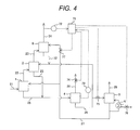
- FIG. 4 is a block diagram showing the system control method according to the present embodiment.
- H 2 S concentration is measured with an H 2 S analyzer 72 and the measured value thereof is input to a controller 71.
- a managed concentration is registered in advance, and a circuit is designed in such a manner that when the concentration measured by the H 2 S analyzer 72 exceeds the managed concentration, a valve 77 is opened.
- the opening degree of the valve 77 increases, an amount of lean solution to be introduced into the secondary absorber 8 is increased and liquid/gas ratio rises, thereby, H 2 S concentration in the treated gas can be decreased.
- a valve 74 may be opened. With this operation, the pressure in the flash drum 4 decreases and a release amount of H 2 S increases, therefore, the H 2 S concentration in the semi-lean solution 28 decreases. In association thereto, the H 2 S concentration in the lean solution 27 also decreases. As a result, H 2 S concentration in the treated gas can be decreased.
- the above three operations can be carried out in any order. Two or more of the operations can be carried out at the same time.
- the method for controlling the H 2 S concentration in the purified gas 24 is explained, although a control of the CO 2 concentration can be performed in the same method.
- FIG. 5 is a block diagram of a device for removing acidic materials in the present embodiment.
- the present embodiment shows an example that is applied to a purifying installation for natural gas.
- Feed gas 121 to which necessary preprocessing and temperature adjustment have been effected beforehand, is supplied to a absorber (second absorber) 101 from a bottom of a first contacting layer 101a in the absorber 101.
- the feed gas 121 contacts in a manner of countercurrent with semi-lean solution 128 supplied from a top of the first contacting layer 101a, and a part of acidic materials, such as CO 2 and H 2 S, included in the feed gas 121 is removed.
- the feed gas is contacted in a manner of countercurrent in a secondary contacting layer 101b with lean solution 127 supplied from a top of the secondary contacting layer 101b, and the acidic materials, such as CO 2 and H 2 S, are further removed and purified gas 124 is obtained.
- rich solution 125 drained from a bottom of the absorber 101 is introduced to a lean/rich exchanger 107 and is heated by the lean solution 127. Because of having passed through the lean/rich exchanger 107, the temperature level of the rich solution 125 is raised by 10 to 50°C higher than that when the rich solution 125 has been exhausted from an outlet of the absorber 101. Depending on necessity, the rich solution 125 is further heated in a rich solution heater 111. By means of heating of the rich solution 125, since a part of CO 2 included in the rich solution 125 is released, the rich solution 125 becomes as a whole in a state of mixed phases of gas and liquid.
- Such rich solution 125 in the state of mixed phases is introduced into a flash drum 104 in which the pressure is set lower than that in the absorber 101, and CO 2 and H 2 S are further released there.
- the released gas is separated herein from the rich solution and is exhausted as stripped gas 126.
- a part of the semi-lean solution 128 separated from the stripped gas 126 in the flash drum 104 is cooled in a first lean solution cooler 112 and thereafter is introduced into the primary absorber 101 from a top of the primary contacting layer 101a.
- the remaining part of the semi-lean solution 128 is introduced into a stripper 105 and is heated by a reboiler 106, and a substantial part of the remaining CO 2 and H 2 S is released and the lean solution 127 is obtained.
- a part of the lean solution 127 is cooled in the lean/rich exchanger 107 and in a second lean solution cooler 113 down to a predetermined temperature and is introduced into the absorber 101 from a top portion of the secondary
- H 2 S concentration in treated gas is required to be reduced to an extremely lower order, such as down to a few ppm, it is necessary to contact the treated gas with lean solution including substantially no H 2 S near an outlet of the treated gas. For this reason, in the present embodiment, the lean solution regenerated in high level in the stripper 105 is supplied from the top of the absorber.
- H 2 S in an order of ppm and CO 2 in an order of % coexist, since a large amount of lean solution has to be circulated for removing CO 2 , a large amount of steam has to be supplied to the reboiler for regenerating the rich solution.
- the semi-lean solution 128 is introduced from the top of the primary contacting layer 101a, a substantial part of CO 2 included in the feed gas 121 is removed, significantly reducing an amount of the lean solution to be supplied from the top of the secondary contacting layer 101b.
- CO 2 concentration is high as in an order of %, CO 2 can be absorbed even in the semi-lean solution in which a certain degree of CO 2 remains in the solution.
- the CO 2 concentration in the semi-lean solution can be adjustable by varying the temperature and the pressure of the flash drum 104.
- the regeneration is accelerated by way of either the semi-lean solution is heated by the rich solution heater 111 or the pressure in the flash drum 104 is reduced.
- an amount of steam used in the reboiler 106 can be significantly reduced.
- the composition of the stripped gas 126 affects the consumed energy in the post process.
- CO 2 separated from the feed gas is frequently stored in the ground or at the sea bottom after being compressed, except for being reused as in a form of gas.
- the stripped gas 126 having a high CO 2 concentration can be obtained.
- CO 2 having less mixture impurities can be obtained, leading to the elimination of an impurity removal at a post process or the laborsaving.
- the lean solution and the semi-lean solution are cooled at a pre stage before they are introduced into the primary absorber 101. This is because of bringing the heated rich solution for regeneration to a temperature suitable for absorbing CO 2 and H 2 S.
- a sixth embodiment of the present invention will be explained with reference to Fig. 6 .
- the present embodiment shows an example in which a pre-absorber (first absorber) 102 is additionally provided at a pre stage of the primary absorber 101 in the fifth embodiment. Only different portions from the fifth embodiment will be explained.
- Feed gas 121 to which necessary preprocessing and temperature adjustment have been effected beforehand, is introduced into the pre-absorber 102, where the feed gas 121 is contacted in a manner of countercurrent with the lean solution 127, and a part of acidic materials, such as CO 2 and H 2 S, included in the feed gas 121 is removed.
- the feed gas 121 is introduced into the absorber 101 and is contacted in a manner of countercurrent with the semi-lean solution 128 in the primary contacting layer 101a and further with the lean solution 127 in the secondary contacting layer 101b, and the remaining acidic materials, such as CO 2 and H 2 S, are removed and the treated gas 124 is obtained.
- rich solution 125a having absorbed a part of acidic materials, such as CO 2 and H 2 S, included in the feed gas 121 in the pre-absorber 102 is heated by the lean solution 127 in the lean/rich exchanger 103, and thereafter, introduced into a flash drum 104a.
- the pressure in the flash drum 104a is set lower than that in the pre-absorber 102, and a part of CO 2 and H 2 S is released from the rich solution 125a.
- the stripped gas 126a released from the rich solution 125a is separated herein from the rich solution, and H 2 S is removed in the post process together with stripped gas 129 released from the stripper 105.
- the rich solution 125a can be further heated at the post stage of the lean/rich exchanger 103.
- the rich solution 125b having absorbed CO 2 and H 2 S remaining in the feed gas 121 in the primary absorber 101 is heated by the lean solution 127 in the lean/rich exchanger 107, and thereafter, further heated by the rich solution heater 111 and introduced into the flash drum 104b.
- the pressure in the flash drum 104b is set lower than that in the primary absorber 101, and a part of CO 2 and H 2 S is released from the rich solution 125b.
- the stripped gas 126b released from the rich solution 125b is separated herein from the rich solution.
- the semi-lean solution which includes remaining CO 2 in a comparatively high concentration, has a low capacity of absorbing H 2 S in an order of ppm. Contrary thereto, the lean solution, substantially including no CO 2 , well absorbs H 2 S even in an order of ppm.
- H 2 S is efficiently removed beforehand. Thereafter, by introducing the feed gas into the primary absorber the H 2 S concentration in the stripped gas 126b can be reduced. In this manner, according to the present embodiment, even when H 2 S concentration in the feed gas 121 is comparatively high, the stripped gas 126b having a high purity of CO 2 can be recovered.
- a seventh embodiment of the present invention will be explained with reference to Fig. 7 .
- the present embodiment shows an example in which H 2 S included in the stripped gas 130 released from the rich solution in the flash drum and in the stripper is removed by making use of an adsorbent, and highly purified CO 2 is recovered.
- the stripped gas 130 including CO 2 and H 2 S is introduced into a knock-out drum 141 where water 150 included in the stripped gas 130 is removed.
- Stripped gas 151 of which water concentration is reduced is introduced through a valve 162 into a catalytic adsorber 146.
- an adsorbent is filled in the catalytic adsorber 146.
- H 2 S included in the stripped gas 151 is adsorbed in the catalytic adsorber 146, and purified CO 2 gas 154 including substantially no H 2 S is obtained through a valve 165.
- valves 161, 164, 166 and 167 are closed.
- the same adsorbent is also filled in another catalytic adsorber 147. When the valves 164 and 167 are opened, the stripped gas 151 can be introduced into the catalytic adsorber 147.
- the adsorbent has features to adsorb H 2 S at a low temperature of 100 to 300°C, and thereafter, to convert the adsorbed sulfur into sulfur dioxide when gas including oxygen is supplied under a temperature of 100 to 600°C, regenerating itself (For example, see Japanese Patent Application Laid-Open Publication No. 52-114589 and No. 52-114590 ).
- a regenerating operation of the adsorbent will be explained.
- a regenerating operation of the adsorbent provided in the catalytic adsorber 147 will be explained.
- gas of which oxygen concentration is adjusted to a predetermined level by mixing a part of regenerated gas 153 with air 169 heated beforehand to a predetermined temperature is supplied via a valve 163.
- the gas which includes oxygen, oxidizes a sulfur component adsorbed in the adsorbent and converts the sulfur component to sulfur dioxide, regenerating the adsorbent.
- the regenerated gas 153 is exhausted via a valve 168 from the catalytic adsorber 147.
- a part of the regenerated gas 153 is mixed with air 169 as has been explained above and is supplied via the valve 163 to the catalytic adsorber 147 performing regeneration.
- the remaining part of the regenerated gas 153 is introduced into desulfurization equipment 144.
- CaCO 3 slurry 155 is circulated, and sulfur dioxide included in the regenerated gas 153 reacts with the CaCO 3 slurry 155 to be fixed as CaSO 4 .
- a part of the CaCO 3 slurry 155 including CaSO 4 is exhausted from the desulfurization equipment 144 to a dehydrator 145, and is separated into CaSO 4 157 and water 158.
- exhaust gas 160 from which sulfur dioxide has been removed is released via a stack to the atmosphere.
- H 2 S concentration in the purified CO 2 gas 154 is always monitored. When the H 2 S concentration exceeds a predetermined level, the stripped gas 151 is introduced into the catalytic adsorber where regeneration is completed by switching the valves. Through repeating this operation, the H 2 S concentration in the purified CO 2 gas 154 to be recovered is always maintained in a predetermined range.
- an adsorbent including at least oxides of titanium and molybdenum can be used.
- the temperature of contacting the regenerated gas 153 with the adsorbent 100 to 300°C is preferable, although the temperature is not limited to this range.
- the regenerating temperature of the adsorbent 100 to 600°C is preferable, although the temperature is not limited to this range.
- the mixture gas of air and the regenerated gas is used for the regeneration of the adsorbent in order to control the temperature of the adsorbent in a predetermined temperature range during the regeneration.
- air alone may be used for the regeneration of the adsorbent.
- stripped gas from a stripper is introduced into desulfurization equipment after the stripped gas is introduced into a combustor and H 2 S is converted into sulfur dioxide.
- H 2 S is converted into sulfur dioxide.
- CO 2 is released as combustion exhaust gas and can not be recovered.
- the present embodiment has an advantage that highly purified CO 2 can be recovered since only H 2 S can be removed from the stripped gas.
- the conventional combustion method has a disadvantage that a large amount of fuel has to be used for heating CO 2 with a large specific heat to a high temperature.
- the adsorbing method shown in the present embodiment can greatly reduce the cost for processing the stripped gas since no fuel is used.
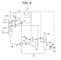
- Fig. 8 is a block diagram showing the system control method according to the present embodiment
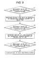
- Fig. 9 is a flowchart of the control method.
- An H 2 S analyzer 172 measures H 2 S concentration in the purified gas 124, and the measured value is input to a controller 171.
- a managed concentration is set in advance. If the concentration measured by the H 2 S analyzer 172 exceeds the managed concentration (step S1), the controller 171 at first increases the opening degree of a valve 176, and then increases a flow rate of steam supplied to the reboiler 106 to accelerate the regeneration of the rich solution (step S2). As a result, since the H 2 S concentration in the lean solution 127 decreases, the H 2 S concentration in the treated gas can be reduced.
- step S3 the opening degree of a valve 175 is enlarged and rate of the semi-lean solution 128 to be introduced into the stripper 105 is increased.
- step S3 the opening degree of a valve 177 is enlarged and an amount of the lean solution to be introduced into the primary absorber 101 is increased.
- step S4 the opening degree of a valve 178 is increased and an amount of cooling water to be introduced into the second lean solution cooler 113 is increased.
- step S5 if H 2 S concentration still exceeds the managed concentration (step S5), a method can be used where, by increasing the opening degree of a valve 179 that adjusts a flow rate of steam to be introduced into the rich solution heater 111, the temperature of the rich solution is raised (step S6) to accelerate the regeneration.
- the above operations are basically performed in the order as explained, although the order can be changed. Two or more of the operations can be carried out at the same time.
- the method for controlling the H 2 S concentration in the treated gas 124 is explained, although a control of the CO 2 concentration can be performed in the same method.
Landscapes
- Chemical & Material Sciences (AREA)
- Oil, Petroleum & Natural Gas (AREA)
- Chemical Kinetics & Catalysis (AREA)
- Organic Chemistry (AREA)
- Engineering & Computer Science (AREA)
- General Chemical & Material Sciences (AREA)
- Analytical Chemistry (AREA)
- Inorganic Chemistry (AREA)
- Gas Separation By Absorption (AREA)
- Treating Waste Gases (AREA)
- Solid-Sorbent Or Filter-Aiding Compositions (AREA)
Abstract
Description
- The present invention relates to a method and a device for removing CO2 and H2S at the same time from a variety of fuel gases including CO2 and H2S.
- In order to suppress global warming, utilization of natural gas having less amount of CO2 generation while combusting compared with other fossil fuels is considered to increase from now on. Natural gas produced from strata includes acidic materials such as CO2 and H2S. CO2 and H2S have to be removed before liquefaction because CO2 solidifies in the process of liquefaction and causes clogging of pipelines and a heat exchanger and H2S induces corrosion of installations such as pipelines. Other than the natural gas, coal seam gas, gas gasified from heavy oil, and gas gasified from oil coke and coal show the same problem as above.
- As a method of removing CO2 and H2S from these gases, a method is disclosed in which feed gas including CO2 and H2S and water solution of N-methyl diethanolamine are contacted under conditions of from 10 to 100 bars and from 40 to 100°C (For example, see
U.S. Patent document No. 4553984 ). - As another method, a method is disclosed in which feed gas including CO2 and H2S is removed by making use of water solution of hindered amine selected from monosubalkylamino subalkanol as rich solution (For example, see Japanese Patent No.
2824387 - Not only in natural gas but also in coal seam gas and gas gasified from heavy oil that can be processed according to the present invention, concentration of CO2 is usually higher than the that of H2S by the order of from 10 to 1000 times. H2S primarily dissolves in advance in rich solution in the regions from a down stage to a middle stage of an absorber and is removed. It has become clear that such phenomenon occurs that the property of the rich solution changes and H2S that has already dissolved therein is released again in association with absorption of CO2 having extremely higher concentration than that of H2S after the above-mentioned dissolution and removal of H2S. For this reason, in order to decrease the property change of the rich solution in association with absorption of CO2 having high concentration, an excess amount of rich solution has to be circulated, causing a problem that an amount of energy to be consumed for regenerating the rich solution is increased. In order to avoid such problem, a method is known in which the pressure of the rich solution that has absorbed CO2 and H2S is lowered and the rich solution is regenerated by releasing the absorbed CO2 and H2S. Unfortunately, this method has a disadvantage that a predetermined performance cannot be obtained at the time of absorption since the concentration of CO2 and H2S remaining in the regenerated rich solution is high.
- An object of the present invention is to provide a method and a device for removing acidic materials, such as CO2 and H2S, in a gas purifying process by contacting gas including CO2 and H2S, such as natural gas, coal seam gas, and gas gasified from heavy oil, with rich solution. The method and the device can reduce the regeneration energy for the rich solution and obtain a treated gas having substantially no H2S concentration.
- The present invention provides a method for removing CO2 and H2S from a feed gas including at least CO2 and H2S. The method comprises a step of introducing the feed gas into a first absorber, and removing CO2 and H2S from the feed gas by contacting the feed gas with a lean solution in the first absorber; and a step of subsequently introducing the feed gas into a second absorber, and further removing CO2 and H2S remaining in the feed gas by contacting the feed gas with a semi-lean solution in the second absorber. A rich solution composed of the lean solution and the semi-lean solution that have absorbed CO2 and H2S in the first absorber and in the second absorber respectively is introduced into a flash drum in which an internal pressure is kept lower than that in the first absorber and in the second absorber. After a part of CO2 and H2S is released from the rich solution and a semi-lean solution is obtained in the flash drum, a part of the semi-lean solution in the flash drum is cooled and introduced into the second absorber to contact again with the feed gas in the second absorber. A remaining part of the semi-lean solution in the flash drum is introduced into a stripper and heated to release remaining CO2 and H2S from the rich solution and a lean solution is obtained in the stripper. A part of the lean solution in the stripper is cooled and introduced into the first absorber to contact again with the feed gas in the first absorber. After a remaining part of the lean solution in the stripper is cooled, the remaining part of the lean solution is introduced into the second absorber from a upper level than a level of where the semi-lean solution from which a part of CO2 and H2S has been released in the flash drum is introduced, and again is contacted with the feed gas in the second absorber, and thereby obtaining treated gas.
- The present invention also provides a method for removing CO2 and H2S from a feed gas including at least CO2 and H2S. The method comprises a step of introducing the feed gas into a first absorber, and removing CO2 and H2S from the feed gas by contacting the feed gas with a lean solution in the first absorber; and a step of subsequently introducing the feed gas into a second absorber, further removing CO2 and H2S remaining in the feed gas by contacting the feed gas with a semi-lean solution in the second absorber, thereafter introducing the feed gas into a third absorber, and further removing CO2 and H2S remaining in the feed gas by contacting the feed gas with a lean solution in the third absorber. A rich solution composed of the lean solution and the semi-lean solution that have absorbed CO2 and H2S in the first absorber and in the second absorber respectively is introduced into a flash drum in which an internal pressure is kept lower than that in the first absorber, in the second absorber, and in the third absorber. After a part of CO2 and H2S is released from the rich solution and a semi-lean solution is obtained in the flash drum, a part of the semi-lean solution in the flash drum is cooled together with the lean solution that has absorbed CO2 and H2S in the third absorber and introduced together into the second absorber to contact with the feed gas in the second absorber. A remaining part of the semi-lean solution in the flash drum is introduced into a stripper and heated to release remaining CO2 and H2S from the rich solution and a lean solution is obtained in the stripper. A part of the lean solution in the stripper is cooled and introduced into the first absorber to contact with the feed gas in the first absorber. After a remaining part of the lean solution in the stripper is cooled, the remaining part of the lean solution is introduced into the third absorber and is contacted with the feed gas in the third absorber, and thereby obtaining treated gas.
- Preferably, the gas including CO2 and H2S released from the rich solution in the flash drum and in the stripper is contacted with an adsorbent including at least oxides of titanium and molybdenum to adsorb and remove H2S in the released gas in a form of sulfide. Successively, a gas including oxygen is introduced into the adsorbent to convert sulfur adsorbed in the adsorbent into a sulfur dioxide gas and to regenerate the adsorbent. An exhaust gas including the sulfur dioxide generated by the regeneration is contacted with CaCO3 slurry to fix the sulfur dioxide in a form of CaSO4 and to separate the sulfur dioxide from the gas.
- In the above method, CO2 concentration and H2S concentration in the treated gas are measured. If the measured CO2 concentration or H2S concentration in the treated gas exceeds a predetermined concentration, an amount of the rich solution to be introduced from the flash drum into the stripper is increased and at the same time an amount of steam to be introduced into a reboiler in the stripper is increased to thereby heighten a rate of the rich solution having been regenerated. Otherwise, the releasing of CO2 and H2S from the rich solution is accelerated by reducing the pressure in the flash drum to thereby lower the concentration of CO2 and H2S in the rich solution.
- According to the present invention, an installation for removing CO2 and H2S from the feed gas, such as natural gas and coal seam gas, by contacting the feed gas with rich solution, can reduce an amount of the rich solution to be circulated and, at the same time, can also reduce the regeneration energy for the rich solution.
-
-
Fig. 1 is a block diagram showing a device for removing acidic materials according to a first embodiment of the present invention; -
Fig. 2 is a block diagram showing a device for removing acidic materials according to a second embodiment of the present invention; -
Fig. 3 is a block diagram showing a device for removing acidic materials according to a third embodiment of the present invention; -
Fig. 4 is a block diagram showing an example of a control method for a system according to the second embodiment of the present invention; -
Fig. 5 is a block diagram showing a device for removing acidic materials according to a fifth embodiment of the present invention; -
Fig. 6 is a block diagram showing a device for removing acidic materials according to a sixth embodiment of the present invention; -
Fig. 7 is a block diagram showing a device for removing acidic materials according to a seventh embodiment of the present invention; -
Fig. 8 is a block diagram showing an example of a control method for a system according to the fifth embodiment of the present invention; and -
Fig. 9 is a flowchart showing an example of a control method for a system according to the fifth embodiment of the present invention. - Gases to be processed according to the present invention include a variety of gases that includes at least CO2 and H2S as acidic materials and of which H2S concentration is low in comparison with CO2 concentration. Examples of such gases include natural gas and coal seam gas.
- Herein below, embodiments of the present invention will be explained, however, the present invention is not limited to the embodiments as follows.
- A first embodiment of the present invention will be explained with reference to
Fig. 1. Fig. 1 is a block diagram of a device for removing acidic materials in the present embodiment. The present embodiment shows an example in which the present invention is applied to an installation for natural gas purification. -
Natural gas 21 representing feed gas, to which necessary preprocessing and temperature adjustment have been effected beforehand, is supplied to a pre-absorber (first absorber) 1. Thefeed gas 21 is contacted in a manner of countercurrent withlean solution 27 supplied from a top of the pre-absorber 1, the acidic materials, such as CO2 and H2S, included in thefeed gas 21 being absorbed there, and pre-treatedgas 22 is exhausted from the top of the pre-absorber 1. On the other hand,rich solution 25 exhausted from a bottom is introduced into a lean/rich exchanger 3 and is heated through heat exchanging with thelean solution 27 introduced into the lean/rich exchanger 3. Because of having passed through the lean/rich exchanger 3, therich solution 25 is heated to a temperature of higher by 10 to 50°C than the temperature at the outlet of the pre-absorber 1. If necessary, therich solution 25 is heated to a further high temperature level by arich solution heater 11. By means of heating therich solution 25, since a part of CO2 absorbed in therich solution 25 is released, therich solution 25 becomes as a whole in a state of mixed phases of gas and liquid. Such primaryrich solution 25 in the state of mixed phases is introduced into aflash drum 4 in which an internal pressure is set lower than that in the pre-absorber 1, and a part of CO2 and H2S, which has been absorbed in therich solution 25, is released and exhausted as mixed strippedgas 26. The more the pressure in theflash drum 4 is lowered than the pressure in the pre-absorber 1, the more a diffusion amount of CO2 and H2S increases. On the other hand, if it is required to liquefy the released CO2 at a post stage, power necessary for the liquefaction increases. When the rich solution is preheated beforehand by making use of waste heat in the lean/rich exchangers 3 or therich solution heater 11, the gas diffuses easily and the pressure in theflash drum 4 can be set comparatively higher, as a result, energy consumed in the entire system can be reduced. - A part of
semi-lean solution 28 after releasing a part of absorbed CO2 and H2S in theflash drum 4 is cooled in alean solution cooler 12, and thereafter is introduced into an absorber (second absorber) 2 from a middle stage of theabsorber 2. On the other hand, the remainingsemi-lean solution 28 that is not introduced into theprimary absorber 2 is introduced into astripper 5, heated by areboiler 6 to release almost all remaining CO2 and H2S, andlean solution 27 is obtained. A part of thelean solution 27 is cooled when passing through the lean/rich exchangers absorber 2 from the top. On the other hand, the remaining part of thelean solution 27 is cooled by alean solution cooler 14 and introduced into the pre-absorber 1 from the top. As in the manner above, by contacting thepre-treated gas 22 with thelean solution 27 including substantially no H2S in the top portion of theabsorber 2, H2S concentration in treated gas is reduced below 5 ppm and H2S can be removed down to a level that satisfies a specification for the flow in pipelines. Further, since thelean solution 27 having absorbed H2S included in thefeed gas 21 is immediately exhausted from the bottom, re-releasing of H2S is suppressed. As a result, the recirculating amount of the rich solution can be reduced. - The
pre-treated gas 22 supplied to theabsorber 2 is contacted in a manner of countercurrent with thesemi-lean solution 28 in a lower layer from a supply port of thesemi-lean solution 28 as well as is contacted in countercurrent with thelean solution 27 in an upper layer from the supply port of thesemi-lean solution 28, thereby, the acidic materials, such as CO2 and H2S, included in thepre-treated gas 22 are absorbed and resulting gas is exhausted from the top of theabsorber 2 as purifiedgas 24. On the other hand, thesemi-lean solution 28 and thelean solution 27 are exhausted from the bottom of theabsorber 2 asrich solution 23 that is heated through heat exchanging with thelean solution 27 in the lean/rich exchanger 7 and, if necessary, is further heated by therich solution heater 11 and then introduced into theflash drum 4. In this heating process, therich solution 23 becomes in a state of mixed phases of gas and liquid. - Stripped
gas 29 including of CO2 and H2S released from thesemi-lean solution 28 in thestripper 5 merges with the strippedgas 26 to form strippedgas 30, which is introduced into an oxidation process of H2S. - A second embodiment of the present invention will be explained with reference to
Fig. 2. Fig. 2 is a block diagram of a device for removing acidic materials in the present embodiment. The present embodiment shows an example in which a secondary absorber (third absorber) 8 is added at a post stage of theabsorber 2 in the first embodiment. Only different portions from the first embodiment will be explained. - The
pre-treated gas 22, which is obtained after a part of CO2 and H2S included in thefeed gas 21 is absorbed in the pre-absorber 1, is contacted in a manner of countercurrent with thesemi-lean solution 28 supplied from the top portion of theabsorber 2 in the filling portion of theabsorber 2, thereby, a part of the acidic materials, such as CO2 and H2S, included in thepre-treated gas 22 is absorbed, and treatedgas 31 is exhausted from the top portion. The treatedgas 31 is contacted in countercurrent with thelean solution 27 supplied from the top portion of thesecondary absorber 8 thereby, almost all of CO2 and H2S remaining in the treatedgas 31 is absorbed, and the purifiedgas 24 including substantially no H2S is obtained from the top portion. - On the other hand,
rich solution 32 exhausted from the bottom of thesecondary absorber 8 merges with thesemi-lean solution 28, cooled together in the lean solution cooler 12 to a predetermined temperature, thereafter, is introduced into theabsorber 2. By cooling the rich solution introduced into theabsorber 2 in such manner, an absorbing capacity is increased. As a result, the circulation amount of the rich solution can be reduced. - A third embodiment of the present invention will be explained with reference to
Fig. 3. Fig. 3 is a block diagram of a device for removing acidic materials in the present embodiment. The present embodiment shows an example in which H2S included in the strippedgas 30 released from the rich solution in the flash drum and the stripper is removed by making use of an adsorbent and highly purified CO2 is recovered. Only different portions from the first embodiment will be explained. - After being cooled in a cooler 40, the stripped
gas 30 including CO2 and H2S is introduced into a knock-out drum 41 wherewater 50 is removed and strippedgas 51 having lowered water concentration is obtained. The strippedgas 51 is introduced through avalve 62 to acatalytic adsorber 46. In thecatalytic adsorber 46, an adsorbent is filled having features to adsorb H2S at a low temperature of 100 to 300°C, and thereafter, to convert the adsorbed sulfur into sulfur dioxide when gas including oxygen is supplied under a temperature of 100 to 600 °C, regenerating itself (For example, see Japanese Patent Application Laid-Open Publication No.52-114589 52-114590 gas 51 is adsorbed, and CO2 gas including substantially no H2S is obtained through avalve 65. At this time,valves - On the other hand, gas of which oxygen concentration is adjusted to a predetermined level by mixing
air 69 to a part of regeneratedgas 53 is supplied to anothercatalytic adsorber 47 via avalve 63. A sulfur component adsorbed in the adsorbent is oxidized to produce sulfur dioxide, and the gas is exhausted via avalve 68 as the regeneratedgas 53. A part of the regeneratedgas 53 is mixed withair 69 as has been explained above and is supplied to thecatalytic adsorber 47 under regeneration. The remaining part of the regeneratedgas 53 is introduced intodesulfurization equipment 44. In thedesulfurization equipment 44, CaCO3 slurry 55 circulates, and sulfur dioxide included in the regeneratedgas 53 reacts with the CaCO3 slurry 55 and is fixed as CaSO4. A part of the CaCO3 slurry 55 including CaSO4 is exhausted from thedesulfurization equipment 44 to adehydrator 45, and is separated intoCaSO 4 57 andwater 58. On the other hand,exhaust gas 60 after being removed of sulfur dioxide is released via a stack to the atmosphere. - At the outlets of the
catalytic adsorbers valves valves gas 51 is introduced to thecatalytic adsorber 47. By repeating this operation, the H2S concentration in the purified CO2 gas 54 to be recovered is always maintained in a predetermined range. - As has been explained above, according to the present invention, at the time when removing H2S by means of adsorption, H2S can be surely removed to an extremely low concentration. Further, not only the adsorbent is recoverable, since the sulfur component is converted to sulfur dioxide during recovery, but also an advantage is obtained that a combustor for combusting H2S and converting sulfur into sulfur dioxide and a mist separator for removing sulfur trioxide mist, which are conventionally required, are unnecessary.
- As the adsorbent filled in the
catalytic adsorbers gas 53 with the adsorbent, 100 to 300 °C is preferable, although the temperature is not limited to this range. As the regenerating temperature of the adsorbent, 100 to 600 °C is preferable, although the temperature is not limited to this range. Air alone can be used for the regeneration of the adsorbent, although the mixture gas of air and the regenerated gas are used in the present embodiment. - In the present embodiment, the oxidation device of H2S is combined with the removing device shown in the first embodiment. However, the oxidation device of H2S can be combined with the removing device shown in other embodiments.
- A fourth embodiment of the present invention will be explained with reference to
Fig. 4 . The present embodiment shows an example that relates to a control method for the system shown in the second embodiment (Fig. 2 ). In the present embodiment, an example of a method of controlling the H2S concentration will be explained.Fig. 4 is a block diagram showing the system control method according to the present embodiment. - With regard to the purified
gas 24, H2S concentration is measured with an H2S analyzer 72 and the measured value thereof is input to acontroller 71. In thecontroller 71, a managed concentration is registered in advance, and a circuit is designed in such a manner that when the concentration measured by the H2S analyzer 72 exceeds the managed concentration, avalve 77 is opened. When the opening degree of thevalve 77 increases, an amount of lean solution to be introduced into thesecondary absorber 8 is increased and liquid/gas ratio rises, thereby, H2S concentration in the treated gas can be decreased. - Further, while monitoring the pressure in the
flash drum 4 with apressure gauge 73, avalve 74 may be opened. With this operation, the pressure in theflash drum 4 decreases and a release amount of H2S increases, therefore, the H2S concentration in thesemi-lean solution 28 decreases. In association thereto, the H2S concentration in thelean solution 27 also decreases. As a result, H2S concentration in the treated gas can be decreased. - Other than the above methods, while increasing the opening degree of a
valve 75, the amount of thesemi-lean solution 28 to be introduced into thestripper 5 is increased, and at the same time while increasing the opening degree of avalve 76, the amount of steam to be supplied to thereboiler 6 can be increased. With this operation, since the amount of thelean solution 27 increases that is regenerated in further high level with respect to the amount of thesemi-lean solution 28, thereby, H2S concentration in the purifiedgas 24 can be decreased. - The above three operations can be carried out in any order. Two or more of the operations can be carried out at the same time. In the present embodiment, the method for controlling the H2S concentration in the purified
gas 24 is explained, although a control of the CO2 concentration can be performed in the same method. - A fifth embodiment of the present invention will be explained with reference to
Fig. 5. Fig. 5 is a block diagram of a device for removing acidic materials in the present embodiment. The present embodiment shows an example that is applied to a purifying installation for natural gas. -
Feed gas 121, to which necessary preprocessing and temperature adjustment have been effected beforehand, is supplied to a absorber (second absorber) 101 from a bottom of a first contactinglayer 101a in theabsorber 101. Thefeed gas 121 contacts in a manner of countercurrent withsemi-lean solution 128 supplied from a top of the first contactinglayer 101a, and a part of acidic materials, such as CO2 and H2S, included in thefeed gas 121 is removed. In succession thereto, the feed gas is contacted in a manner of countercurrent in a secondary contactinglayer 101b withlean solution 127 supplied from a top of the secondary contactinglayer 101b, and the acidic materials, such as CO2 and H2S, are further removed and purifiedgas 124 is obtained. On the other hand,rich solution 125 drained from a bottom of theabsorber 101 is introduced to a lean/rich exchanger 107 and is heated by thelean solution 127. Because of having passed through the lean/rich exchanger 107, the temperature level of therich solution 125 is raised by 10 to 50°C higher than that when therich solution 125 has been exhausted from an outlet of theabsorber 101. Depending on necessity, therich solution 125 is further heated in arich solution heater 111. By means of heating of therich solution 125, since a part of CO2 included in therich solution 125 is released, therich solution 125 becomes as a whole in a state of mixed phases of gas and liquid. Suchrich solution 125 in the state of mixed phases is introduced into aflash drum 104 in which the pressure is set lower than that in theabsorber 101, and CO2 and H2S are further released there. The released gas is separated herein from the rich solution and is exhausted as strippedgas 126. A part of thesemi-lean solution 128 separated from the strippedgas 126 in theflash drum 104 is cooled in a firstlean solution cooler 112 and thereafter is introduced into theprimary absorber 101 from a top of the primary contactinglayer 101a. The remaining part of thesemi-lean solution 128 is introduced into astripper 105 and is heated by areboiler 106, and a substantial part of the remaining CO2 and H2S is released and thelean solution 127 is obtained. A part of thelean solution 127 is cooled in the lean/rich exchanger 107 and in a second lean solution cooler 113 down to a predetermined temperature and is introduced into theabsorber 101 from a top portion of the secondary contactinglayer 101b. - Generally, since H2S concentration in treated gas is required to be reduced to an extremely lower order, such as down to a few ppm, it is necessary to contact the treated gas with lean solution including substantially no H2S near an outlet of the treated gas. For this reason, in the present embodiment, the lean solution regenerated in high level in the
stripper 105 is supplied from the top of the absorber. However, when H2S in an order of ppm and CO2 in an order of % coexist, since a large amount of lean solution has to be circulated for removing CO2, a large amount of steam has to be supplied to the reboiler for regenerating the rich solution. On the other hand, in the present embodiment, since thesemi-lean solution 128 is introduced from the top of the primary contactinglayer 101a, a substantial part of CO2 included in thefeed gas 121 is removed, significantly reducing an amount of the lean solution to be supplied from the top of the secondary contactinglayer 101b. This is because that since CO2 concentration is high as in an order of %, CO2 can be absorbed even in the semi-lean solution in which a certain degree of CO2 remains in the solution. The CO2 concentration in the semi-lean solution can be adjustable by varying the temperature and the pressure of theflash drum 104. If the CO2 concentration in the semi-lean solution is desired to be reduced, the regeneration is accelerated by way of either the semi-lean solution is heated by therich solution heater 111 or the pressure in theflash drum 104 is reduced. As has been explained hithereto, according to the present embodiment, since a substantial part of CO2 is removed by the regenerated semi-lean solution without using steam, an amount of steam used in thereboiler 106 can be significantly reduced. - On the other hand, the composition of the stripped
gas 126 affects the consumed energy in the post process. CO2 separated from the feed gas is frequently stored in the ground or at the sea bottom after being compressed, except for being reused as in a form of gas. In the present embodiment, by optimizing the kind of rich solution or the temperature and pressure of the primary absorber and the flash drum, the strippedgas 126 having a high CO2 concentration can be obtained. As a result, CO2 having less mixture impurities can be obtained, leading to the elimination of an impurity removal at a post process or the laborsaving. - As has been explained above, by reducing the pressure in the
flash drum 104, CO2 concentration in the semi-lean solution can be reduced. However, on the other hand, since the pressure of the strippedgas 126 including of CO2 released from the rich solution also reduces, if it is required to liquefy the strippedgas 126 in a post process, the power required for the compression process is increased. Accordingly, as shown in the present embodiment, when the rich solution being introduced into theflash drum 104 is heated by making use of the retaining heat in thelean solution 127 by using the lean/rich exchanger 107, the regeneration is accelerated and the CO2 concentration in the semi-lean solution can be reduced and at the same time the power for compressing the stripped gas at the post process can be reduced. - Further, in the present embodiment, the lean solution and the semi-lean solution are cooled at a pre stage before they are introduced into the
primary absorber 101. This is because of bringing the heated rich solution for regeneration to a temperature suitable for absorbing CO2 and H2S. - A sixth embodiment of the present invention will be explained with reference to
Fig. 6 . The present embodiment shows an example in which a pre-absorber (first absorber) 102 is additionally provided at a pre stage of theprimary absorber 101 in the fifth embodiment. Only different portions from the fifth embodiment will be explained. -
Feed gas 121, to which necessary preprocessing and temperature adjustment have been effected beforehand, is introduced into the pre-absorber 102, where thefeed gas 121 is contacted in a manner of countercurrent with thelean solution 127, and a part of acidic materials, such as CO2 and H2S, included in thefeed gas 121 is removed. In succession thereto, thefeed gas 121 is introduced into theabsorber 101 and is contacted in a manner of countercurrent with thesemi-lean solution 128 in the primary contactinglayer 101a and further with thelean solution 127 in the secondary contactinglayer 101b, and the remaining acidic materials, such as CO2 and H2S, are removed and the treatedgas 124 is obtained. - On the other hand,
rich solution 125a having absorbed a part of acidic materials, such as CO2 and H2S, included in thefeed gas 121 in the pre-absorber 102 is heated by thelean solution 127 in the lean/rich exchanger 103, and thereafter, introduced into aflash drum 104a. The pressure in theflash drum 104a is set lower than that in the pre-absorber 102, and a part of CO2 and H2S is released from therich solution 125a. The strippedgas 126a released from therich solution 125a is separated herein from the rich solution, and H2S is removed in the post process together with strippedgas 129 released from thestripper 105. Depending on necessity, therich solution 125a can be further heated at the post stage of the lean/rich exchanger 103. - The
rich solution 125b having absorbed CO2 and H2S remaining in thefeed gas 121 in theprimary absorber 101 is heated by thelean solution 127 in the lean/rich exchanger 107, and thereafter, further heated by therich solution heater 111 and introduced into theflash drum 104b. The pressure in theflash drum 104b is set lower than that in theprimary absorber 101, and a part of CO2 and H2S is released from therich solution 125b. The strippedgas 126b released from therich solution 125b is separated herein from the rich solution. - The semi-lean solution, which includes remaining CO2 in a comparatively high concentration, has a low capacity of absorbing H2S in an order of ppm. Contrary thereto, the lean solution, substantially including no CO2, well absorbs H2S even in an order of ppm. By contacting the feed gas at first with the lean solution, H2S is efficiently removed beforehand. Thereafter, by introducing the feed gas into the primary absorber the H2S concentration in the stripped
gas 126b can be reduced. In this manner, according to the present embodiment, even when H2S concentration in thefeed gas 121 is comparatively high, the strippedgas 126b having a high purity of CO2 can be recovered. - A seventh embodiment of the present invention will be explained with reference to
Fig. 7 . The present embodiment shows an example in which H2S included in the strippedgas 130 released from the rich solution in the flash drum and in the stripper is removed by making use of an adsorbent, and highly purified CO2 is recovered. - After being cooled in a cooler 140, the stripped
gas 130 including CO2 and H2S is introduced into a knock-out drum 141 wherewater 150 included in the strippedgas 130 is removed. Strippedgas 151 of which water concentration is reduced is introduced through a valve 162 into acatalytic adsorber 146. In thecatalytic adsorber 146, an adsorbent is filled. Accordingly, H2S included in the strippedgas 151 is adsorbed in thecatalytic adsorber 146, and purified CO2 gas 154 including substantially no H2S is obtained through avalve 165. At this time,valves catalytic adsorber 147. When thevalves gas 151 can be introduced into thecatalytic adsorber 147. - The adsorbent has features to adsorb H2S at a low temperature of 100 to 300°C, and thereafter, to convert the adsorbed sulfur into sulfur dioxide when gas including oxygen is supplied under a temperature of 100 to 600°C, regenerating itself (For example, see Japanese Patent Application Laid-Open Publication No.
52-114589 52-114590 - Now, a regenerating operation of the adsorbent will be explained. Herein, a regenerating operation of the adsorbent provided in the
catalytic adsorber 147 will be explained. To thecatalytic adsorber 147, gas of which oxygen concentration is adjusted to a predetermined level by mixing a part of regeneratedgas 153 withair 169 heated beforehand to a predetermined temperature is supplied via avalve 163. The gas, which includes oxygen, oxidizes a sulfur component adsorbed in the adsorbent and converts the sulfur component to sulfur dioxide, regenerating the adsorbent. The regeneratedgas 153 is exhausted via avalve 168 from thecatalytic adsorber 147. A part of the regeneratedgas 153 is mixed withair 169 as has been explained above and is supplied via thevalve 163 to thecatalytic adsorber 147 performing regeneration. The remaining part of the regeneratedgas 153 is introduced intodesulfurization equipment 144. In the desulfurization equipment (gypsum recovering equipment) 144, CaCO3 slurry 155 is circulated, and sulfur dioxide included in the regeneratedgas 153 reacts with the CaCO3 slurry 155 to be fixed as CaSO4. A part of the CaCO3 slurry 155 including CaSO4 is exhausted from thedesulfurization equipment 144 to adehydrator 145, and is separated intoCaSO 4 157 andwater 158. On the other hand,exhaust gas 160 from which sulfur dioxide has been removed is released via a stack to the atmosphere. - H2S concentration in the purified CO2 gas 154 is always monitored. When the H2S concentration exceeds a predetermined level, the stripped
gas 151 is introduced into the catalytic adsorber where regeneration is completed by switching the valves. Through repeating this operation, the H2S concentration in the purified CO2 gas 154 to be recovered is always maintained in a predetermined range. - As the adsorbent used in the present embodiment, for example, an adsorbent including at least oxides of titanium and molybdenum can be used. As the temperature of contacting the regenerated
gas 153 with the adsorbent, 100 to 300°C is preferable, although the temperature is not limited to this range. As the regenerating temperature of the adsorbent, 100 to 600°C is preferable, although the temperature is not limited to this range. In the present embodiment, the mixture gas of air and the regenerated gas is used for the regeneration of the adsorbent in order to control the temperature of the adsorbent in a predetermined temperature range during the regeneration. However, air alone may be used for the regeneration of the adsorbent. - Conventionally, stripped gas from a stripper is introduced into desulfurization equipment after the stripped gas is introduced into a combustor and H2S is converted into sulfur dioxide. However, with this combustion method, CO2 is released as combustion exhaust gas and can not be recovered. The present embodiment has an advantage that highly purified CO2 can be recovered since only H2S can be removed from the stripped gas. When the H2S concentration is low and the CO2 concentration is high in stripped gas, the conventional combustion method has a disadvantage that a large amount of fuel has to be used for heating CO2 with a large specific heat to a high temperature. Contrary thereto, the adsorbing method shown in the present embodiment can greatly reduce the cost for processing the stripped gas since no fuel is used.
- Eighth embodiment of the present invention will be explained with reference to
Figs. 8 and9 . The present embodiment is an example that relates to a control method for the system shown in the fifth embodiment (Fig. 5 ) . In the present embodiment, an example of a method for controlling the H2S concentration in the treatedgas 124 will be explained.Fig. 8 is a block diagram showing the system control method according to the present embodiment, andFig. 9 is a flowchart of the control method. - An H2S analyzer 172 measures H2S concentration in the purified
gas 124, and the measured value is input to acontroller 171. In thecontroller 171, a managed concentration is set in advance. If the concentration measured by the H2S analyzer 172 exceeds the managed concentration (step S1), thecontroller 171 at first increases the opening degree of avalve 176, and then increases a flow rate of steam supplied to thereboiler 106 to accelerate the regeneration of the rich solution (step S2). As a result, since the H2S concentration in thelean solution 127 decreases, the H2S concentration in the treated gas can be reduced. - In spite of the operation as explained above, if H2S concentration still exceeds the managed concentration (step S3), the opening degree of a
valve 175 is enlarged and rate of thesemi-lean solution 128 to be introduced into thestripper 105 is increased. At the same time, the opening degree of avalve 177 is enlarged and an amount of the lean solution to be introduced into theprimary absorber 101 is increased. Further, at the same time with the above operation, the opening degree of avalve 178 is increased and an amount of cooling water to be introduced into the second lean solution cooler 113 is increased (step S4). - Even in spite of the operation as explained above, if H2S concentration still exceeds the managed concentration (step S5), a method can be used where, by increasing the opening degree of a
valve 179 that adjusts a flow rate of steam to be introduced into therich solution heater 111, the temperature of the rich solution is raised (step S6) to accelerate the regeneration. - When a flow rate of the lean solution with respect to the semi lean solution to be introduced into the
primary absorber 101 is increased, an average loading of the rich solution reduces. More specifically, by opening thevalve 177, the flow rate of thelean solution 127 to be introduced into theprimary absorber 101 is increased. Thereby, liquid/gas ratio in theprimary absorber 101 rises, and the H2S concentration in the treated gas can be decreased. - The above operations are basically performed in the order as explained, although the order can be changed. Two or more of the operations can be carried out at the same time. In the present embodiment, the method for controlling the H2S concentration in the treated
gas 124 is explained, although a control of the CO2 concentration can be performed in the same method. - Features, components and specific details of the structures of the above-described embodiments may be exchanged or combined to form further embodiments optimized for the respective application. As far as those modifications are apparent for an expert skilled in the art they shall be disclosed implicitly by the above description without specifying explicitly every possible combination.
Claims (10)
- A method for removing CO2 and H2S from a feed gas (21) including at least CO2 and H2S, comprising:a step of introducing the feed gas (21) into a first absorber (1), and removing CO2 and H2S from the feed gas (21) by contacting the feed gas (21) with a lean solution (27) in the first absorber (1); anda step of subsequently introducing the feed gas (21) into a second absorber (2), and further removing CO2 and H2S remaining in the feed gas (21) by contacting the feed gas (21) with a semi-lean solution (28) in the second absorber (2);wherein a rich solution (25) composed of the lean solution (27) and the semi-lean solution (28) that have absorbed CO2 and H2S in the first absorber (1) and in the second absorber (2) respectively is introduced into a flash drum (4) in which an internal pressure is kept lower than that in the first absorber (1) and in the second absorber (2); after a part of CO2 and H2S is released from the rich solution (25) and a semi-lean solution (28) is obtained in the flash drum (4), a part of the semi-lean solution (28) in the flash drum (4) is cooled and introduced into the second absorber (2) to contact again with the feed gas (21) in the second absorber (2); a remaining part of the semi-lean solution (28) in the flash drum (4) is introduced into a stripper (5) and heated to release remaining CO2 and H2S from the rich solution (25) and a lean solution (27) is obtained in the stripper (5); a part of the lean solution (27) in the stripper (5) is cooled and introduced into the first absorber (1) to contact again with the feed gas (21) in the first absorber (1); and
after a remaining part of the lean solution (27) in the stripper (5) is cooled, the remaining part of the lean solution (27) is introduced into the second absorber (2) from a upper level than a level of where the semi-lean solution (28) from which a part of CO2 and H2S has been released in the flash drum (4) is introduced, and again is contacted with the feed gas (21) in the second absorber (2), and thereby obtaining treated gas. - A method for removing CO2 and H2S from a feed gas (21) including at least CO2 and H2S, comprising:a step of introducing the feed gas (21) into a first absorber (1), and removing CO2 and H2S from the feed gas (21) by contacting the feed gas (21) with a lean solution (27) in the first absorber (1); and a step of subsequently introducing the feed gas (21) into a second absorber (2), further removing CO2 and H2S remaining in the feed gas (21) by contacting the feed gas (21) with a semi-lean solution (28) in the second absorber (2), thereafter introducing the feed gas (21) into a third absorber (8), and further removing CO2 and H2S remaining in the feed gas (21) by contacting the feed gas (21) with a lean solution (27) in the third absorber (8);wherein a rich solution (25) composed of the lean solution (27) and the semi-lean solution (28) that have absorbed CO2 and H2S in the first absorber (1) and in the second absorber (2) respectively is introduced into a flash drum (4) in which an internal pressure is kept lower than that in the first absorber (1), in the second absorber (2), and in the third absorber (8); after a part of CO2 and H2S is released from the rich solution (25) and a semi-lean solution (28) is obtained in the flash drum (4), a part of the semi-lean solution (28) in the flash drum (4) is cooled together with the lean solution (27) that has absorbed CO2 and H2S in the third absorber (8) and introduced together into the second absorber (2) to contact with the feed gas (21) in the second absorber (2); a remaining part of the semi-lean solution (28) in the flash drum (4) is introduced into a stripper (5) and heated to release remaining CO2 and H2S from the rich solution (25) and a lean solution (27) is obtained in the stripper (5); a part of the lean solution (27) in the stripper (5) is cooled and introduced into the first absorber (1) to contact with the feed gas (21) in the first absorber (1); and after a remaining part of the lean solution (27) in the stripper (5) is cooled, the remaining part of the lean solution (27) is introduced into the third absorber (8) and is contacted with the feed gas (21) in the third absorber (8), and thereby obtaining treated gas.
- A method for removing CO2 and H2S according to claim 1 or 2,
wherein the gas including CO2 and H2S released from the rich solution (25) in the flash drum (4) and in the stripper (5) is contacted with an adsorbent including at least oxides of titanium and molybdenum to adsorb and remove H2S in the released gas in a form of sulfide; successively, a gas including oxygen is introduced into the adsorbent to convert sulfur adsorbed in the adsorbent into a sulfur dioxide gas and to regenerate the adsorbent; and an exhaust gas including the sulfur dioxide generated by the regeneration is contacted with CaCO3 slurry to fix the sulfur dioxide in a form of CaSO4 and to separate the sulfur dioxide from the gas. - A method for removing CO2 and H2S according to claim 3,
wherein the gas including CO2 and H2S released from the rich solution (25) in the flash drum (4) and in the stripper (5) is contacted with the adsorbent under a temperature of 100 to 300°C; and subsequently at the time of the regeneration the adsorbent is contacted with the gas including oxygen under 100 to 600°C. - A method for removing CO2 and H2S according to claim 3,
wherein a part of the regenerated gas is introduced as the gas including oxygen used for the regeneration of the adsorbent. - A method for removing CO2 and H2S according to at least one of claims 1 to 5,
wherein CO2 concentration and H2S concentration in the treated gas are measured; and if the measured CO2 concentration or H2S concentration in the treated gas exceeds a predetermined concentration, an amount of the rich solution (25) to be introduced from the flash drum (4) into the stripper (5) is increased and at the same time an amount of steam to be introduced into a reboiler in the stripper (5) is increased to thereby heighten a rate of the rich solution (25) having been regenerated. - A method for removing CO2 and H2S according to at least one of claims 1 to 5,
wherein CO2 concentration and H2S concentration in the treated gas are measured, and if the measured CO2 concentration or H2S concentration in the treated gas exceeds a predetermined concentration, the releasing of CO2 and H2S from the rich solution (25) is accelerated by reducing the pressure in the flash drum (4) to thereby lower the concentration of CO2 and H2S in the rich solution. - A device for removing CO2 and H2S from a feed gas (21) including at least CO2 and H2S, comprising:a first absorber (1) for removing CO2 and H2S from the feed gas (21) by contacting the feed gas (21) with a lean solution (27) and;a second absorber (2) for further removing CO2 and H2S remaining in the feed gas (21) passed through the first absorber (1) by contacting the feed gas (21) with a semi-lean solution (28) and;a flash drum (4) in which an internal pressure is kept lower than that in the first absorber (1) and in the second absorber (2) to release CO2 and H2S from a rich solution (25) introduced from the first absorber (1) and the second absorber (2), the rich solution (25) being composed of the lean solution (27) and the semi-lean solution (28);a stripper (5) that heats the semi-lean solution (28) from which a part of CO2 and H2S has been released in the flash drum (4) to further release CO2 and H2S remaining in the semi-lean solution (28);a first lean solution cooler for cooling the semi-lean solution (28) regenerated in the flash drum (4) before introducing the semi-lean solution (28) into the second absorber (2);a second lean solution cooler for cooling the lean solution (27) regenerated in the stripper (5) before introducing the lean solution (27) into the second absorber (2); anda third lean solution cooler for cooling the lean solution (27) regenerated in the stripper (5) before introducing the lean solution (27) into the first absorber (1);wherein the second absorber (2) has at least two supply ports to introduce the solution, and one of these supply ports is arranged to introduce the lean solution (27) into the second absorber (2) at a position nearer to a top portion and another is arranged to introduce the semi-lean solution (28) at a position lower than the one.
- A device for removing CO2 and H2S from a feed gas (21) including at least CO2 and H2S, comprising:a first absorber (1) for removing CO2 and H2S from the feed gas (21) by contacting the feed gas (21) with a lean solution (27) and;a second absorber (2) for removing CO2 and H2S remaining in the feed gas (21) passed through the first absorber (1) by contacting the feed gas (21) with a semi-lean solution (28) and;a third absorber (8) for further removing CO2 and H2S remaining in the feed gas (21) passed through the second absorber (2) by contacting the feed gas (21) with a lean solution (27) and;a flash drum (4) in which an internal pressure is kept lower than that in the first absorber (1), in the second absorber (2), and in the third absorber (8) to release CO2 and H2S from a rich solution (25) introduced from the first absorber (1) and the second absorber (2), the rich solution (25) being composed of the lean solution (27) and the semi-lean solution (28);a stripper (5) that heats the semi-lean solution (28) from which a part of CO2 and H2S has been released in the flash drum (4) to further release CO2 and H2S remaining in the semi-lean solution (28);a first lean solution cooler for cooling the semi-lean solution (28) regenerated in the flash drum (4) before introducing the semi-lean solution (28) into the second absorber (2);a second lean solution cooler for cooling a part of the lean solution (27) regenerated in the stripper (5) before introducing the part of the lean solution (27) into the third absorber (8); anda third lean solution cooler for cooling a remaining part of the lean solution (27) regenerated in the stripper (5) before introducing the remaining part of the lean solution (27) into the first absorber (1).
- A method for removing CO2 and H2S from a feed gas (21) including at least CO2 and H2S, comprising:a step of introducing the feed gas (21) into an absorber including a first contacting layer and a second contacting layer from a bottom of the first contacting layer, contacting the feed gas (21) with a semi-lean solution (28) in the first contacting layer and subsequently with a lean solution (27) in the second contacting layer to remove CO2 and H2S from the feed gas (21), and thereby obtaining treated gas;a step of draining a rich solution (25), being composed of the semi-lean solution (28) and the lean solution (27) that have absorbed CO2 and H2S in the absorber, from the bottom of the absorber, introducing the rich solution (25) into a flash drum (4) in which an internal pressure is kept lower than that in the absorber, and thereby releasing CO2 from the rich solution (25) in the flash drum (4) and a semi-lean solution (28) is obtained; anda step of introducing a part of the semi-lean solution (28) from which CO2 has been released mainly in the flash drum (4) into the absorber from an upper level of the first contacting layer, introducing a remaining part of the semi-lean solution (28) into a stripper (5), heating the remaining part of the semi-lean solution (28) to release CO2 and H2S remaining in it and a lean solution (27) is obtained, and introducing the lean solution (27) into the absorber from an upper portion of the second contacting layer.
Applications Claiming Priority (1)
| Application Number | Priority Date | Filing Date | Title |
|---|---|---|---|
| JP2008273292 | 2008-10-23 |
Publications (3)
| Publication Number | Publication Date |
|---|---|
| EP2179777A2 true EP2179777A2 (en) | 2010-04-28 |
| EP2179777A3 EP2179777A3 (en) | 2012-04-25 |
| EP2179777B1 EP2179777B1 (en) | 2016-05-04 |
Family
ID=41528120
Family Applications (1)
| Application Number | Title | Priority Date | Filing Date |
|---|---|---|---|
| EP09173960.7A Active EP2179777B1 (en) | 2008-10-23 | 2009-10-23 | Method and device for removing CO2 and H2S |
Country Status (5)
| Country | Link |
|---|---|
| US (1) | US8435325B2 (en) |
| EP (1) | EP2179777B1 (en) |
| JP (1) | JP5425586B2 (en) |
| CN (1) | CN101721883B (en) |
| AU (1) | AU2009227884B2 (en) |
Cited By (4)
| Publication number | Priority date | Publication date | Assignee | Title |
|---|---|---|---|---|
| CN106823691A (en) * | 2017-02-21 | 2017-06-13 | 西南化工研究设计院有限公司 | A kind of method of hydrogen sulfide gas concentrate |
| EP3199223A1 (en) * | 2012-02-27 | 2017-08-02 | Kabushiki Kaisha Toshiba | Carbon dioxide separating and collecting system and method of operating same |
| US20180326348A1 (en) * | 2016-05-11 | 2018-11-15 | Uop Llc | Methods and apparatuses for gas separation by solvent or absorbent |
| EP3501622A1 (en) * | 2017-12-22 | 2019-06-26 | L'air Liquide, Société Anonyme Pour L'Étude Et L'exploitation Des Procédés Georges Claude | Absorber column and method for purifying raw synthesis gas |
Families Citing this family (31)
| Publication number | Priority date | Publication date | Assignee | Title |
|---|---|---|---|---|
| CN102463024B (en) * | 2010-11-15 | 2013-12-04 | 攀钢集团钢铁钒钛股份有限公司 | Treatment method of sulfur removing pregnant solution |
| JP5697411B2 (en) | 2010-11-17 | 2015-04-08 | 株式会社東芝 | Carbon dioxide recovery device and carbon dioxide recovery method |
| JP5591075B2 (en) * | 2010-11-24 | 2014-09-17 | 三菱重工業株式会社 | CO2 and H2S containing gas recovery system and method |
| CN102258928B (en) * | 2011-05-18 | 2013-12-25 | 成都华西工业气体有限公司 | Pressurized heat regeneration procedure of desulfurization solvent in flue gas desulfurization by utilizing solvent cycle absorption method |
| JP2013000666A (en) * | 2011-06-17 | 2013-01-07 | Hitachi Ltd | Method of treating gas containing hydrogen sulfide |
| US9068128B2 (en) | 2011-10-18 | 2015-06-30 | Baker Hughes Incorporated | Method for reducing hydrogen sulfide evolution from asphalt and heavy fuel oils |
| AU2012343386B2 (en) * | 2011-12-01 | 2015-09-24 | Kabushiki Kaisha Toshiba | Carbon dioxide recovery device, carbon dioxide recovery method, and amine compound recovery method |
| JP5868741B2 (en) * | 2012-03-09 | 2016-02-24 | 三菱重工業株式会社 | Acid gas removal device |
| US8945292B2 (en) * | 2012-03-23 | 2015-02-03 | General Electric Company | System for recovering acid gases from a gas stream |
| CN102698568A (en) * | 2012-06-07 | 2012-10-03 | 中国华能集团清洁能源技术研究院有限公司 | Enhanced cooling and multistage regeneration carbon dioxide capture and regeneration system |
| JP6300802B2 (en) * | 2012-09-05 | 2018-03-28 | ビーエーエスエフ ソシエタス・ヨーロピアBasf Se | Method for separating acid gases from fluid streams containing water |
| CN102895860B (en) * | 2012-09-29 | 2015-01-07 | 华北电力大学 | Method and system for reducing consumption of chemical absorption CO2 capture process |
| JP6071622B2 (en) * | 2013-02-21 | 2017-02-01 | 三菱重工業株式会社 | CO2 and H2S containing gas recovery system and method |
| JP5995746B2 (en) * | 2013-02-21 | 2016-09-21 | 三菱重工業株式会社 | CO2 and H2S containing gas recovery system and method |
| US9731243B2 (en) | 2014-06-30 | 2017-08-15 | Uop Llc | Low pressure re-absorber and its integration with sulfur-rich solvent flash drum or sulfur-rich solvent stripper in an absorption unit |
| KR101883878B1 (en) | 2016-08-22 | 2018-08-01 | 한양대학교 산학협력단 | Apparatus and method for removing acidic gas containing natural gas |
| US10537823B2 (en) * | 2017-02-15 | 2020-01-21 | Hall Labs Llc | Method for removal of carbon dioxide from a carrier liquid |
| CN108686486B (en) * | 2017-04-12 | 2021-01-15 | 北京华石联合能源科技发展有限公司 | Reproducible suspension bed wet desulphurization process |
| WO2019039687A1 (en) * | 2017-08-25 | 2019-02-28 | 한국전력공사 | Acid gas collection apparatus |
| KR102248010B1 (en) * | 2018-05-23 | 2021-05-06 | 닛키 글로벌 가부시키가이샤 | Natural gas pretreatment facility |
| CA3129318A1 (en) * | 2019-02-13 | 2020-09-03 | Chevron U.S.A. Inc. | Coating compositions for erosion mitigation, and coated components and methods using said coatings |
| CN110628479A (en) * | 2019-09-26 | 2019-12-31 | 江苏城乡建设职业学院 | Energy-saving method and system for deep decarburization of natural gas |
| CN111453703B (en) * | 2020-03-31 | 2023-05-12 | 陕西聚能新创煤化科技有限公司 | Method and device for producing high-concentration hydrogen sulfide by purifying low-temperature methanol |
| US11471821B2 (en) | 2020-04-18 | 2022-10-18 | Indian Oil Corporation Limited | Process for biogas upgradation |
| EP4405433A1 (en) * | 2021-09-21 | 2024-07-31 | Eastman Chemical Company | Pyrolysis gas treatment using absorber-stripper system |
| CN114835118A (en) * | 2022-05-07 | 2022-08-02 | 宁夏紫光天化蛋氨酸有限责任公司 | Method for removing hydrogen sulfide from carbon disulfide |
| CN114797387A (en) * | 2022-05-31 | 2022-07-29 | 华能营口热电有限责任公司 | Flue gas deep carbon capture device and method for recovering waste heat |
| CN115138181B (en) * | 2022-05-31 | 2024-11-01 | 华能营口热电有限责任公司 | Energy-saving and water-saving carbon capture device and method |
| CN115957597B (en) * | 2022-11-25 | 2024-05-10 | 新疆敦华绿碳技术股份有限公司 | Desorption device and carbon dioxide production system |
| WO2024201895A1 (en) * | 2023-03-30 | 2024-10-03 | 三菱重工業株式会社 | Carbon dioxide recovery system |
| US20250249402A1 (en) * | 2024-02-05 | 2025-08-07 | Saudi Arabian Oil Company | Systems and methods for eliminating flaring in amine sweetening |
Citations (4)
| Publication number | Priority date | Publication date | Assignee | Title |
|---|---|---|---|---|
| JPS52114590A (en) | 1976-03-24 | 1977-09-26 | Babcock Hitachi Kk | Treatment of h2s containing gas and adsorbent therefor |
| JPS52114589A (en) | 1976-03-24 | 1977-09-26 | Babcock Hitachi Kk | Treatment of h2s containing gas and adsorbent therefor |
| US4553984A (en) | 1984-03-06 | 1985-11-19 | Basf Aktiengesellschaft | Removal of CO2 and/or H2 S from gases |
| JP2824387B2 (en) | 1994-03-18 | 1998-11-11 | 関西電力株式会社 | Method for removing hydrogen sulfide and carbon dioxide in gas |
Family Cites Families (37)
| Publication number | Priority date | Publication date | Assignee | Title |
|---|---|---|---|---|
| DE1494806C3 (en) | 1966-10-14 | 1975-07-10 | Metallgesellschaft Ag, 6000 Frankfurt | Process for hydrogen sulfide and carbon dioxide scrubbing of fuel and synthesis gases and regeneration of the loaded detergent |
| US3531914A (en) * | 1967-12-19 | 1970-10-06 | Stone Container Corp | Packaging machine |
| US3609942A (en) * | 1968-09-18 | 1971-10-05 | Phillips Petroleum Co | High pressure gas dehydration with liquid desiccant |
| US3664091A (en) * | 1969-06-27 | 1972-05-23 | Fish Engineering & Constructio | Process and system for removing acid gas from natural gas |
| US4330305A (en) | 1976-03-19 | 1982-05-18 | Basf Aktiengesellschaft | Removal of CO2 and/or H2 S from gases |
| DE2611613B2 (en) | 1976-03-19 | 1979-04-26 | Basf Ag, 6700 Ludwigshafen | Process for the separation of CO2 and / or H25 from gases containing these components |
| US4106916A (en) * | 1977-08-10 | 1978-08-15 | Phillips Petroleum Company | Automatic control of an absorption/stripping process |
| US4405584A (en) * | 1982-02-02 | 1983-09-20 | Exxon Research And Engineering Co. | Process for removing acidic gases |
| NL8600030A (en) * | 1986-01-09 | 1987-08-03 | Shell Int Research | REMOVAL OF ACID GASES FROM A GAS MIX. |
| US4702898A (en) * | 1986-10-17 | 1987-10-27 | Union Carbide Corporation | Process for the removal of acid gases from gas mixtures |
| JPH07114927B2 (en) | 1990-02-23 | 1995-12-13 | 三菱重工業株式会社 | ▲ High ▼ Refining method of warm reducing gas |
| US6071484A (en) * | 1997-01-24 | 2000-06-06 | Mpr Services, Inc. | Process for treating gas with ultra-lean amine |
| JP4287915B2 (en) | 1997-03-07 | 2009-07-01 | 三菱重工業株式会社 | Method and apparatus for treating hydrogen sulfide in gas |
| JP3217742B2 (en) * | 1997-11-11 | 2001-10-15 | 関西電力株式会社 | Method and apparatus for controlling carbon dioxide absorbing liquid |
| FR2820430B1 (en) * | 2001-02-02 | 2003-10-31 | Inst Francais Du Petrole | PROCESS FOR DEACIDIFYING A GAS WITH WASHING OF DESORBED HYDROCARBONS DURING THE REGENERATION OF THE SOLVENT |
| US7147691B2 (en) * | 2002-09-27 | 2006-12-12 | 1058238 Alberta Ltd. | Acid gas enrichment process |
| DE10313438A1 (en) * | 2003-03-26 | 2004-11-04 | Uhde Gmbh | Process for the selective removal of hydrogen sulfide and CO2 from raw gas |
| JP4436068B2 (en) | 2003-04-30 | 2010-03-24 | 株式会社クリーンコールパワー研究所 | Coal gasification plant, coal gasification method, coal gasification power plant, and expansion facility for coal gasification plant |
| WO2004108244A2 (en) | 2003-06-05 | 2004-12-16 | Basf Aktiengesellschaft | Method for the deacidification of a fluid stream by means of an inert scrubbing column and corresponding device |
| JP2005139225A (en) | 2003-11-04 | 2005-06-02 | Mitsubishi Heavy Ind Ltd | Desulfurization apparatus |
| JP5030371B2 (en) | 2004-04-15 | 2012-09-19 | 三菱重工業株式会社 | Absorbing liquid, apparatus and method for removing CO2 and / or H2S using absorbing liquid |
| EP1769092A4 (en) | 2004-06-29 | 2008-08-06 | Europ Nickel Plc | Improved leaching of base metals |
| CA2567790C (en) * | 2004-07-12 | 2013-01-08 | Exxonmobil Upstream Research Company | Methods for removing sulfur-containing compounds |
| WO2006024030A2 (en) * | 2004-08-24 | 2006-03-02 | Advanced Extraction Technologies, Inc. | Combined use of external and internal solvents in processing gases containing light, medium and heavy components |
| JP2006150298A (en) | 2004-11-30 | 2006-06-15 | Mitsubishi Heavy Ind Ltd | Absorption liquid, and co2 or h2s removal apparatus and method employing it |
| JP5039276B2 (en) | 2004-12-13 | 2012-10-03 | 三菱重工業株式会社 | Absorbing liquid, apparatus and method for removing CO2 or H2S in gas using absorbing liquid |
| CA2576454C (en) | 2005-04-04 | 2010-06-08 | Mitsubishi Heavy Industries, Ltd. | Absorbing solution that removes any one of co2 and h2s or both, and method and apparatus that uses the absorbing solution |
| JP2007000702A (en) | 2005-06-21 | 2007-01-11 | Kansai Electric Power Co Inc:The | Liquid absorbent, and device and method for removing co2 or h2s, or both |
| FR2897785B1 (en) | 2006-02-28 | 2009-06-05 | Inst Francais Du Petrole | OPTIMIZED COS REMOVAL PROCESS |
| JP5230080B2 (en) | 2006-06-06 | 2013-07-10 | 三菱重工業株式会社 | Absorption liquid, CO2 removal apparatus and method |
| TW200801513A (en) | 2006-06-29 | 2008-01-01 | Fermiscan Australia Pty Ltd | Improved process |
| WO2008097839A1 (en) | 2007-02-02 | 2008-08-14 | Chevron U.S.A. Inc. | Methods and apparatus for removing acid gases from a natural gas stream |
| US8480982B2 (en) | 2007-02-22 | 2013-07-09 | Fluor Technologies Corporation | Configurations and methods for carbon dioxide and hydrogen production from gasification streams |
| JP2008307520A (en) | 2007-06-18 | 2008-12-25 | Mitsubishi Heavy Ind Ltd | Co2 or h2s removal system, co2 or h2s removal method |
| JP5215595B2 (en) | 2007-06-18 | 2013-06-19 | 三菱重工業株式会社 | Absorbing liquid, CO2 or H2S removing apparatus and method using absorbing liquid |
| US7967896B2 (en) * | 2008-03-26 | 2011-06-28 | Uop Llc | Use of hydraulic turbocharger for recovering energy from high pressure solvents in gasification and natural gas applications |
| JP5039651B2 (en) * | 2008-07-08 | 2012-10-03 | 三菱重工業株式会社 | Carbon dioxide recovery system in exhaust gas |
-
2009
- 2009-10-19 US US12/581,725 patent/US8435325B2/en active Active
- 2009-10-20 AU AU2009227884A patent/AU2009227884B2/en active Active
- 2009-10-21 JP JP2009241958A patent/JP5425586B2/en active Active
- 2009-10-23 CN CN2009102054039A patent/CN101721883B/en active Active
- 2009-10-23 EP EP09173960.7A patent/EP2179777B1/en active Active
Patent Citations (4)
| Publication number | Priority date | Publication date | Assignee | Title |
|---|---|---|---|---|
| JPS52114590A (en) | 1976-03-24 | 1977-09-26 | Babcock Hitachi Kk | Treatment of h2s containing gas and adsorbent therefor |
| JPS52114589A (en) | 1976-03-24 | 1977-09-26 | Babcock Hitachi Kk | Treatment of h2s containing gas and adsorbent therefor |
| US4553984A (en) | 1984-03-06 | 1985-11-19 | Basf Aktiengesellschaft | Removal of CO2 and/or H2 S from gases |
| JP2824387B2 (en) | 1994-03-18 | 1998-11-11 | 関西電力株式会社 | Method for removing hydrogen sulfide and carbon dioxide in gas |
Cited By (7)
| Publication number | Priority date | Publication date | Assignee | Title |
|---|---|---|---|---|
| EP3199223A1 (en) * | 2012-02-27 | 2017-08-02 | Kabushiki Kaisha Toshiba | Carbon dioxide separating and collecting system and method of operating same |
| US20180326348A1 (en) * | 2016-05-11 | 2018-11-15 | Uop Llc | Methods and apparatuses for gas separation by solvent or absorbent |
| CN106823691A (en) * | 2017-02-21 | 2017-06-13 | 西南化工研究设计院有限公司 | A kind of method of hydrogen sulfide gas concentrate |
| CN106823691B (en) * | 2017-02-21 | 2019-07-16 | 西南化工研究设计院有限公司 | A kind of method of hydrogen sulfide gas concentrate |
| EP3501622A1 (en) * | 2017-12-22 | 2019-06-26 | L'air Liquide, Société Anonyme Pour L'Étude Et L'exploitation Des Procédés Georges Claude | Absorber column and method for purifying raw synthesis gas |
| WO2019120616A1 (en) * | 2017-12-22 | 2019-06-27 | L'air Liquide, Societe Anonyme Pour L'etude Et L'exploitation Des Procedes Georges Claude | Absorber column and process for cleaning crude synthesis gas |
| US11634325B2 (en) | 2017-12-22 | 2023-04-25 | L'Air Liquide, Société Anonyme pour l'Etude et l'Exploitation des Procédés Georges Claude | Absorber column and process for cleaning crude synthesis gas |
Also Published As
| Publication number | Publication date |
|---|---|
| CN101721883A (en) | 2010-06-09 |
| JP2010120013A (en) | 2010-06-03 |
| AU2009227884A1 (en) | 2010-05-13 |
| JP5425586B2 (en) | 2014-02-26 |
| CN101721883B (en) | 2013-07-24 |
| AU2009227884B2 (en) | 2010-09-30 |
| US20100101416A1 (en) | 2010-04-29 |
| US8435325B2 (en) | 2013-05-07 |
| EP2179777B1 (en) | 2016-05-04 |
| EP2179777A3 (en) | 2012-04-25 |
Similar Documents
| Publication | Publication Date | Title |
|---|---|---|
| US8435325B2 (en) | Method and device for removing CO2 and H2S | |
| AU2012264072C9 (en) | CO2 recovery method and apparatus | |
| US8012446B1 (en) | Recycle TSA regen gas to boiler for oxyfuel operations | |
| JP5567185B2 (en) | Blast furnace gas separation method | |
| CN103958029B (en) | Hydrogen sulfide separation method and device, and hydrogen production system using the same | |
| WO2008097839A1 (en) | Methods and apparatus for removing acid gases from a natural gas stream | |
| JP4216152B2 (en) | Desulfurization decarboxylation method and apparatus | |
| WO2022101323A1 (en) | Facility for producing gaseous biomethane by purifying biogas from landfill combining membranes, cryodistillation and deoxo | |
| KR101038764B1 (en) | Carbon dioxide separation and recovery device and its processing method | |
| JP4959303B2 (en) | Exhaust gas treatment method and treatment apparatus | |
| JP2010069371A (en) | Apparatus for recovering carbon dioxide in coal boiler exhaust gas in thermal power plant and method for recovering carbon dioxide | |
| CA2856293A1 (en) | Direct reduced iron manufacturing system | |
| EP2258996A1 (en) | Method for separating blast furnace gas | |
| Biernat | Review of technology for cleaning biogas to natural gas quality | |
| US7695702B2 (en) | Optimization of amine regeneration system start-up using flash tank pressurization | |
| US20070284240A1 (en) | System and method for diagnosing and troubleshooting amine regeneration system | |
| KR20180053161A (en) | CO2 recovery method using phase separation during CO2 absorption in hydrazine aqueous solution | |
| JP5074116B2 (en) | Regenerative desulfurization apparatus and desulfurization system | |
| JP4287915B2 (en) | Method and apparatus for treating hydrogen sulfide in gas | |
| JP4772307B2 (en) | Dry desulfurization apparatus, mercury removal method from dry desulfurization apparatus, and regeneration tower | |
| EP3403713A1 (en) | Co2 recovery device and recovery method | |
| CN113731098A (en) | Environmental-friendly resourceful treatment system and process flow for fireflooding tail gas | |
| JPH07136456A (en) | Method and apparatus for advanced desulfurization and denitration of exhaust gas | |
| JPS6257628A (en) | Pretreatment of by-product gas from ironworks | |
| AU2007258038A1 (en) | Optimization of amine regeneration system start-up using flash tank pressurization |
Legal Events
| Date | Code | Title | Description |
|---|---|---|---|
| PUAI | Public reference made under article 153(3) epc to a published international application that has entered the european phase |
Free format text: ORIGINAL CODE: 0009012 |
|
| 17P | Request for examination filed |
Effective date: 20100226 |
|
| AK | Designated contracting states |
Kind code of ref document: A2 Designated state(s): AT BE BG CH CY CZ DE DK EE ES FI FR GB GR HR HU IE IS IT LI LT LU LV MC MK MT NL NO PL PT RO SE SI SK SM TR |
|
| AX | Request for extension of the european patent |
Extension state: AL BA RS |
|
| PUAL | Search report despatched |
Free format text: ORIGINAL CODE: 0009013 |
|
| AK | Designated contracting states |
Kind code of ref document: A3 Designated state(s): AT BE BG CH CY CZ DE DK EE ES FI FR GB GR HR HU IE IS IT LI LT LU LV MC MK MT NL NO PL PT RO SE SI SK SM TR |
|
| AX | Request for extension of the european patent |
Extension state: AL BA RS |
|
| RIC1 | Information provided on ipc code assigned before grant |
Ipc: B01D 53/14 20060101AFI20120319BHEP |
|
| 17Q | First examination report despatched |
Effective date: 20130410 |
|
| RAP1 | Party data changed (applicant data changed or rights of an application transferred) |
Owner name: MITSUBISHI HITACHI POWER SYSTEMS, LTD. |
|
| RAP1 | Party data changed (applicant data changed or rights of an application transferred) |
Owner name: MITSUBISHI HITACHI POWER SYSTEMS, LTD. |
|
| GRAP | Despatch of communication of intention to grant a patent |
Free format text: ORIGINAL CODE: EPIDOSNIGR1 |
|
| INTG | Intention to grant announced |
Effective date: 20151106 |
|
| GRAS | Grant fee paid |
Free format text: ORIGINAL CODE: EPIDOSNIGR3 |
|
| GRAA | (expected) grant |
Free format text: ORIGINAL CODE: 0009210 |
|
| AK | Designated contracting states |
Kind code of ref document: B1 Designated state(s): AT BE BG CH CY CZ DE DK EE ES FI FR GB GR HR HU IE IS IT LI LT LU LV MC MK MT NL NO PL PT RO SE SI SK SM TR |
|
| REG | Reference to a national code |
Ref country code: GB Ref legal event code: FG4D |
|
| REG | Reference to a national code |
Ref country code: CH Ref legal event code: EP |
|
| REG | Reference to a national code |
Ref country code: AT Ref legal event code: REF Ref document number: 796398 Country of ref document: AT Kind code of ref document: T Effective date: 20160515 |
|
| REG | Reference to a national code |
Ref country code: IE Ref legal event code: FG4D |
|
| REG | Reference to a national code |
Ref country code: NL Ref legal event code: FP |
|
| REG | Reference to a national code |
Ref country code: DE Ref legal event code: R096 Ref document number: 602009038329 Country of ref document: DE |
|
| REG | Reference to a national code |
Ref country code: LT Ref legal event code: MG4D |
|
| PG25 | Lapsed in a contracting state [announced via postgrant information from national office to epo] |
Ref country code: NO Free format text: LAPSE BECAUSE OF FAILURE TO SUBMIT A TRANSLATION OF THE DESCRIPTION OR TO PAY THE FEE WITHIN THE PRESCRIBED TIME-LIMIT Effective date: 20160804 Ref country code: FI Free format text: LAPSE BECAUSE OF FAILURE TO SUBMIT A TRANSLATION OF THE DESCRIPTION OR TO PAY THE FEE WITHIN THE PRESCRIBED TIME-LIMIT Effective date: 20160504 Ref country code: LT Free format text: LAPSE BECAUSE OF FAILURE TO SUBMIT A TRANSLATION OF THE DESCRIPTION OR TO PAY THE FEE WITHIN THE PRESCRIBED TIME-LIMIT Effective date: 20160504 |
|
| REG | Reference to a national code |
Ref country code: AT Ref legal event code: MK05 Ref document number: 796398 Country of ref document: AT Kind code of ref document: T Effective date: 20160504 |
|
| PG25 | Lapsed in a contracting state [announced via postgrant information from national office to epo] |
Ref country code: PT Free format text: LAPSE BECAUSE OF FAILURE TO SUBMIT A TRANSLATION OF THE DESCRIPTION OR TO PAY THE FEE WITHIN THE PRESCRIBED TIME-LIMIT Effective date: 20160905 Ref country code: GR Free format text: LAPSE BECAUSE OF FAILURE TO SUBMIT A TRANSLATION OF THE DESCRIPTION OR TO PAY THE FEE WITHIN THE PRESCRIBED TIME-LIMIT Effective date: 20160805 Ref country code: LV Free format text: LAPSE BECAUSE OF FAILURE TO SUBMIT A TRANSLATION OF THE DESCRIPTION OR TO PAY THE FEE WITHIN THE PRESCRIBED TIME-LIMIT Effective date: 20160504 Ref country code: SE Free format text: LAPSE BECAUSE OF FAILURE TO SUBMIT A TRANSLATION OF THE DESCRIPTION OR TO PAY THE FEE WITHIN THE PRESCRIBED TIME-LIMIT Effective date: 20160504 Ref country code: ES Free format text: LAPSE BECAUSE OF FAILURE TO SUBMIT A TRANSLATION OF THE DESCRIPTION OR TO PAY THE FEE WITHIN THE PRESCRIBED TIME-LIMIT Effective date: 20160504 Ref country code: HR Free format text: LAPSE BECAUSE OF FAILURE TO SUBMIT A TRANSLATION OF THE DESCRIPTION OR TO PAY THE FEE WITHIN THE PRESCRIBED TIME-LIMIT Effective date: 20160504 |
|
| PG25 | Lapsed in a contracting state [announced via postgrant information from national office to epo] |
Ref country code: IT Free format text: LAPSE BECAUSE OF FAILURE TO SUBMIT A TRANSLATION OF THE DESCRIPTION OR TO PAY THE FEE WITHIN THE PRESCRIBED TIME-LIMIT Effective date: 20160504 |
|
| PG25 | Lapsed in a contracting state [announced via postgrant information from national office to epo] |
Ref country code: EE Free format text: LAPSE BECAUSE OF FAILURE TO SUBMIT A TRANSLATION OF THE DESCRIPTION OR TO PAY THE FEE WITHIN THE PRESCRIBED TIME-LIMIT Effective date: 20160504 Ref country code: DK Free format text: LAPSE BECAUSE OF FAILURE TO SUBMIT A TRANSLATION OF THE DESCRIPTION OR TO PAY THE FEE WITHIN THE PRESCRIBED TIME-LIMIT Effective date: 20160504 Ref country code: SK Free format text: LAPSE BECAUSE OF FAILURE TO SUBMIT A TRANSLATION OF THE DESCRIPTION OR TO PAY THE FEE WITHIN THE PRESCRIBED TIME-LIMIT Effective date: 20160504 Ref country code: CZ Free format text: LAPSE BECAUSE OF FAILURE TO SUBMIT A TRANSLATION OF THE DESCRIPTION OR TO PAY THE FEE WITHIN THE PRESCRIBED TIME-LIMIT Effective date: 20160504 Ref country code: RO Free format text: LAPSE BECAUSE OF FAILURE TO SUBMIT A TRANSLATION OF THE DESCRIPTION OR TO PAY THE FEE WITHIN THE PRESCRIBED TIME-LIMIT Effective date: 20160504 |
|
| REG | Reference to a national code |
Ref country code: DE Ref legal event code: R097 Ref document number: 602009038329 Country of ref document: DE |
|
| PG25 | Lapsed in a contracting state [announced via postgrant information from national office to epo] |
Ref country code: PL Free format text: LAPSE BECAUSE OF FAILURE TO SUBMIT A TRANSLATION OF THE DESCRIPTION OR TO PAY THE FEE WITHIN THE PRESCRIBED TIME-LIMIT Effective date: 20160504 Ref country code: BE Free format text: LAPSE BECAUSE OF FAILURE TO SUBMIT A TRANSLATION OF THE DESCRIPTION OR TO PAY THE FEE WITHIN THE PRESCRIBED TIME-LIMIT Effective date: 20160504 Ref country code: AT Free format text: LAPSE BECAUSE OF FAILURE TO SUBMIT A TRANSLATION OF THE DESCRIPTION OR TO PAY THE FEE WITHIN THE PRESCRIBED TIME-LIMIT Effective date: 20160504 Ref country code: SM Free format text: LAPSE BECAUSE OF FAILURE TO SUBMIT A TRANSLATION OF THE DESCRIPTION OR TO PAY THE FEE WITHIN THE PRESCRIBED TIME-LIMIT Effective date: 20160504 |
|
| PLBE | No opposition filed within time limit |
Free format text: ORIGINAL CODE: 0009261 |
|
| STAA | Information on the status of an ep patent application or granted ep patent |
Free format text: STATUS: NO OPPOSITION FILED WITHIN TIME LIMIT |
|
| 26N | No opposition filed |
Effective date: 20170207 |
|
| REG | Reference to a national code |
Ref country code: DE Ref legal event code: R119 Ref document number: 602009038329 Country of ref document: DE Ref country code: DE Ref legal event code: R409 Ref document number: 602009038329 Country of ref document: DE |
|
| PG25 | Lapsed in a contracting state [announced via postgrant information from national office to epo] |
Ref country code: SI Free format text: LAPSE BECAUSE OF FAILURE TO SUBMIT A TRANSLATION OF THE DESCRIPTION OR TO PAY THE FEE WITHIN THE PRESCRIBED TIME-LIMIT Effective date: 20160504 |
|
| REG | Reference to a national code |
Ref country code: CH Ref legal event code: PL |
|
| GBPC | Gb: european patent ceased through non-payment of renewal fee |
Effective date: 20161023 |
|
| PG25 | Lapsed in a contracting state [announced via postgrant information from national office to epo] |
Ref country code: MC Free format text: LAPSE BECAUSE OF FAILURE TO SUBMIT A TRANSLATION OF THE DESCRIPTION OR TO PAY THE FEE WITHIN THE PRESCRIBED TIME-LIMIT Effective date: 20160504 |
|
| REG | Reference to a national code |
Ref country code: DE Ref legal event code: R409 Ref document number: 602009038329 Country of ref document: DE |
|
| REG | Reference to a national code |
Ref country code: IE Ref legal event code: MM4A |
|
| REG | Reference to a national code |
Ref country code: FR Ref legal event code: ST Effective date: 20170630 |
|
| PG25 | Lapsed in a contracting state [announced via postgrant information from national office to epo] |
Ref country code: GB Free format text: LAPSE BECAUSE OF NON-PAYMENT OF DUE FEES Effective date: 20161023 Ref country code: FR Free format text: LAPSE BECAUSE OF NON-PAYMENT OF DUE FEES Effective date: 20161102 Ref country code: CH Free format text: LAPSE BECAUSE OF NON-PAYMENT OF DUE FEES Effective date: 20161031 Ref country code: LI Free format text: LAPSE BECAUSE OF NON-PAYMENT OF DUE FEES Effective date: 20161031 |
|
| PG25 | Lapsed in a contracting state [announced via postgrant information from national office to epo] |
Ref country code: LU Free format text: LAPSE BECAUSE OF NON-PAYMENT OF DUE FEES Effective date: 20161023 |
|
| PG25 | Lapsed in a contracting state [announced via postgrant information from national office to epo] |
Ref country code: IE Free format text: LAPSE BECAUSE OF NON-PAYMENT OF DUE FEES Effective date: 20161023 |
|
| PG25 | Lapsed in a contracting state [announced via postgrant information from national office to epo] |
Ref country code: HU Free format text: LAPSE BECAUSE OF FAILURE TO SUBMIT A TRANSLATION OF THE DESCRIPTION OR TO PAY THE FEE WITHIN THE PRESCRIBED TIME-LIMIT; INVALID AB INITIO Effective date: 20091023 Ref country code: CY Free format text: LAPSE BECAUSE OF FAILURE TO SUBMIT A TRANSLATION OF THE DESCRIPTION OR TO PAY THE FEE WITHIN THE PRESCRIBED TIME-LIMIT Effective date: 20160504 |
|
| PG25 | Lapsed in a contracting state [announced via postgrant information from national office to epo] |
Ref country code: MK Free format text: LAPSE BECAUSE OF FAILURE TO SUBMIT A TRANSLATION OF THE DESCRIPTION OR TO PAY THE FEE WITHIN THE PRESCRIBED TIME-LIMIT Effective date: 20160504 Ref country code: TR Free format text: LAPSE BECAUSE OF FAILURE TO SUBMIT A TRANSLATION OF THE DESCRIPTION OR TO PAY THE FEE WITHIN THE PRESCRIBED TIME-LIMIT Effective date: 20160504 Ref country code: MT Free format text: LAPSE BECAUSE OF NON-PAYMENT OF DUE FEES Effective date: 20161031 Ref country code: IS Free format text: LAPSE BECAUSE OF FAILURE TO SUBMIT A TRANSLATION OF THE DESCRIPTION OR TO PAY THE FEE WITHIN THE PRESCRIBED TIME-LIMIT Effective date: 20160504 |
|
| PG25 | Lapsed in a contracting state [announced via postgrant information from national office to epo] |
Ref country code: BG Free format text: LAPSE BECAUSE OF FAILURE TO SUBMIT A TRANSLATION OF THE DESCRIPTION OR TO PAY THE FEE WITHIN THE PRESCRIBED TIME-LIMIT Effective date: 20160504 |
|
| REG | Reference to a national code |
Ref country code: DE Ref legal event code: R082 Ref document number: 602009038329 Country of ref document: DE Representative=s name: MERH-IP MATIAS ERNY REICHL HOFFMANN PATENTANWA, DE Ref country code: DE Ref legal event code: R081 Ref document number: 602009038329 Country of ref document: DE Owner name: MITSUBISHI POWER, LTD., JP Free format text: FORMER OWNER: MITSUBISHI HITACHI POWER SYSTEMS, LTD., YOKOHAMA, JP |
|
| REG | Reference to a national code |
Ref country code: NL Ref legal event code: HC Owner name: MITSUBISHI POWER, LTD.; JP Free format text: DETAILS ASSIGNMENT: CHANGE OF OWNER(S), CHANGE OF OWNER(S) NAME; FORMER OWNER NAME: MITSUBISHI HITACHI POWER SYSTEMS, LTD. Effective date: 20210114 |
|
| PGFP | Annual fee paid to national office [announced via postgrant information from national office to epo] |
Ref country code: NL Payment date: 20250912 Year of fee payment: 17 |
|
| PGFP | Annual fee paid to national office [announced via postgrant information from national office to epo] |
Ref country code: DE Payment date: 20250902 Year of fee payment: 17 |