EP2179326B1 - Laser bi-frequence fibre par melange d'ondes dans des fibres optiques amplificatrices - Google Patents
Laser bi-frequence fibre par melange d'ondes dans des fibres optiques amplificatrices Download PDFInfo
- Publication number
- EP2179326B1 EP2179326B1 EP08775283.8A EP08775283A EP2179326B1 EP 2179326 B1 EP2179326 B1 EP 2179326B1 EP 08775283 A EP08775283 A EP 08775283A EP 2179326 B1 EP2179326 B1 EP 2179326B1
- Authority
- EP
- European Patent Office
- Prior art keywords
- optical
- frequency
- fibre
- dual
- wave
- Prior art date
- Legal status (The legal status is an assumption and is not a legal conclusion. Google has not performed a legal analysis and makes no representation as to the accuracy of the status listed.)
- Active
Links
Images



Classifications
-
- H—ELECTRICITY
- H01—ELECTRIC ELEMENTS
- H01S—DEVICES USING THE PROCESS OF LIGHT AMPLIFICATION BY STIMULATED EMISSION OF RADIATION [LASER] TO AMPLIFY OR GENERATE LIGHT; DEVICES USING STIMULATED EMISSION OF ELECTROMAGNETIC RADIATION IN WAVE RANGES OTHER THAN OPTICAL
- H01S3/00—Lasers, i.e. devices using stimulated emission of electromagnetic radiation in the infrared, visible or ultraviolet wave range
- H01S3/09—Processes or apparatus for excitation, e.g. pumping
- H01S3/091—Processes or apparatus for excitation, e.g. pumping using optical pumping
- H01S3/094—Processes or apparatus for excitation, e.g. pumping using optical pumping by coherent light
- H01S3/0941—Processes or apparatus for excitation, e.g. pumping using optical pumping by coherent light of a laser diode
- H01S3/09415—Processes or apparatus for excitation, e.g. pumping using optical pumping by coherent light of a laser diode the pumping beam being parallel to the lasing mode of the pumped medium, e.g. end-pumping
-
- H—ELECTRICITY
- H01—ELECTRIC ELEMENTS
- H01S—DEVICES USING THE PROCESS OF LIGHT AMPLIFICATION BY STIMULATED EMISSION OF RADIATION [LASER] TO AMPLIFY OR GENERATE LIGHT; DEVICES USING STIMULATED EMISSION OF ELECTROMAGNETIC RADIATION IN WAVE RANGES OTHER THAN OPTICAL
- H01S3/00—Lasers, i.e. devices using stimulated emission of electromagnetic radiation in the infrared, visible or ultraviolet wave range
- H01S3/05—Construction or shape of optical resonators; Accommodation of active medium therein; Shape of active medium
- H01S3/06—Construction or shape of active medium
- H01S3/063—Waveguide lasers, i.e. whereby the dimensions of the waveguide are of the order of the light wavelength
- H01S3/067—Fibre lasers
- H01S3/06708—Constructional details of the fibre, e.g. compositions, cross-section, shape or tapering
- H01S3/06712—Polarising fibre; Polariser
-
- H—ELECTRICITY
- H01—ELECTRIC ELEMENTS
- H01S—DEVICES USING THE PROCESS OF LIGHT AMPLIFICATION BY STIMULATED EMISSION OF RADIATION [LASER] TO AMPLIFY OR GENERATE LIGHT; DEVICES USING STIMULATED EMISSION OF ELECTROMAGNETIC RADIATION IN WAVE RANGES OTHER THAN OPTICAL
- H01S3/00—Lasers, i.e. devices using stimulated emission of electromagnetic radiation in the infrared, visible or ultraviolet wave range
- H01S3/05—Construction or shape of optical resonators; Accommodation of active medium therein; Shape of active medium
- H01S3/06—Construction or shape of active medium
- H01S3/063—Waveguide lasers, i.e. whereby the dimensions of the waveguide are of the order of the light wavelength
- H01S3/067—Fibre lasers
- H01S3/0675—Resonators including a grating structure, e.g. distributed Bragg reflectors [DBR] or distributed feedback [DFB] fibre lasers
-
- H—ELECTRICITY
- H01—ELECTRIC ELEMENTS
- H01S—DEVICES USING THE PROCESS OF LIGHT AMPLIFICATION BY STIMULATED EMISSION OF RADIATION [LASER] TO AMPLIFY OR GENERATE LIGHT; DEVICES USING STIMULATED EMISSION OF ELECTROMAGNETIC RADIATION IN WAVE RANGES OTHER THAN OPTICAL
- H01S3/00—Lasers, i.e. devices using stimulated emission of electromagnetic radiation in the infrared, visible or ultraviolet wave range
- H01S3/05—Construction or shape of optical resonators; Accommodation of active medium therein; Shape of active medium
- H01S3/08—Construction or shape of optical resonators or components thereof
- H01S3/08086—Multiple-wavelength emission
- H01S3/0809—Two-wavelenghth emission
-
- H—ELECTRICITY
- H01—ELECTRIC ELEMENTS
- H01S—DEVICES USING THE PROCESS OF LIGHT AMPLIFICATION BY STIMULATED EMISSION OF RADIATION [LASER] TO AMPLIFY OR GENERATE LIGHT; DEVICES USING STIMULATED EMISSION OF ELECTROMAGNETIC RADIATION IN WAVE RANGES OTHER THAN OPTICAL
- H01S3/00—Lasers, i.e. devices using stimulated emission of electromagnetic radiation in the infrared, visible or ultraviolet wave range
- H01S3/09—Processes or apparatus for excitation, e.g. pumping
- H01S3/091—Processes or apparatus for excitation, e.g. pumping using optical pumping
- H01S3/094—Processes or apparatus for excitation, e.g. pumping using optical pumping by coherent light
- H01S3/0941—Processes or apparatus for excitation, e.g. pumping using optical pumping by coherent light of a laser diode
-
- H—ELECTRICITY
- H01—ELECTRIC ELEMENTS
- H01S—DEVICES USING THE PROCESS OF LIGHT AMPLIFICATION BY STIMULATED EMISSION OF RADIATION [LASER] TO AMPLIFY OR GENERATE LIGHT; DEVICES USING STIMULATED EMISSION OF ELECTROMAGNETIC RADIATION IN WAVE RANGES OTHER THAN OPTICAL
- H01S3/00—Lasers, i.e. devices using stimulated emission of electromagnetic radiation in the infrared, visible or ultraviolet wave range
- H01S3/14—Lasers, i.e. devices using stimulated emission of electromagnetic radiation in the infrared, visible or ultraviolet wave range characterised by the material used as the active medium
- H01S3/16—Solid materials
- H01S3/1601—Solid materials characterised by an active (lasing) ion
- H01S3/1603—Solid materials characterised by an active (lasing) ion rare earth
- H01S3/1608—Solid materials characterised by an active (lasing) ion rare earth erbium
Definitions
- the invention relates to "all-fiber" bi-frequency lasers comprising two-wave mixing in polarization-maintaining amplifying optical fibers.
- Each of the two optical frequencies obtained propagates in rectilinear polarization according to one of the proper axes of the fiber.
- Such lasers are intended to meet the need for microwave sources of very high spectral purity, necessary in future generations of radar systems, but also more generally, for the distribution of frequency references in complex systems and in fiber sensors.
- optical fibers have the following fundamental advantages over the coaxial cable: their losses are low (0.3 dB / km against 1000 dB / km for cables ), and their dispersion is negligible over a wide microwave bandwidth (an optical carrier, with a frequency around 100 THz, can be modulated over a range of 20 to 40 GHz without limits due to the chromatic dispersion of the fiber, the band passing a cable not exceeding a few GHz).
- the beat has a spectral width lower than kHz and that the surrounding phase noise is of the order of -130 dBc / Hz at 10 kHz of the central frequency of the signal
- the dBc unit means decibels relative to the carrier (decibel relative to the carrier in English) and represents the ratio (in decibels) of power of a signal compared to his carrier.
- the unit dB is considered as SI unit, but can be replaced by 10xlog10 (signal power / carrier power)
- a first method consists of using two-frequency laser diodes or two coupled laser diodes as described in the following references: T. Hidaka, S. Matsuura, M. Tani and K. Sakai, "CW terahertz wave generation by photomixing using a two-longitudinal diode laser mode", Electron. Lett. Flight. 33, 2039 (1997) ) MD Pelusi, HF Liu and D. Novak, "THz optical beat frequency generation from a single mode locked semiconductor laser", Appl. Phys. Lett. Flight. 71, 449 (1997) ) X. Wang, W. Mao, M. Al-Mumin, SA Pappert, J. Hong and G. Li, "Optical generation of microwave / millimeter-wave signals using two-section gain-coupled DFB lasers", IEEE Phot. Tech. Lett. Flight. 11, No. 10, 1292 (1999) ).
- the microwave beat obtained has excellent spectral characteristics: the spectral width can be less than kHz and the phase noise level at the foot of the signal perfectly meets the radar requirements (up to - 130 dBc / Hz at 20 kHz from the microwave carrier).
- the tunability of the generated microwave signal extends over a few GHz.
- the subject of the invention is a fiber-based dual-frequency laser comprising an optical source emitting at least one main optical wave at a first wavelength, a fiber-amplified medium characterized in that it comprises means for interfering with two waves primary optics from the main optical wave so as to create a diffraction grating within said amplifying medium, the main optical wave being thus diffracted by said created diffraction grating, into a second optical wave emitting at a second length of wave.
- the amplifying medium comprises a polarization-maintaining doped fiber.
- the dual-frequency laser comprises a coupler for creating the two primary optical waves from the main optical wave.
- the fiber amplified medium comprises an optical circulator.
- the amplifying medium comprises an optical fiber, an optical pump and a wavelength multiplexer.
- the amplifying medium comprises a doped optical fiber having two concentric sheaths or several cores.
- the dual-frequency laser comprises a circulator in the path of each of the primary optical waves, so as to recover at the output of said dual-frequency laser, two secondary optical waves.
- the amplifying medium comprises an optical fiber, two optical pumps and two wavelength multiplexers.
- the dual-frequency laser comprises means of reflection of said main wave so as to create the diffraction grating by interference between said main optical wave and the reflected wave of said main optical wave.
- the reflection means may comprise a component of the Bragg mirror or metal mirror type.
- the reflection means may also comprise an optical fiber incorporating a reflective end with respect to the main optical wave.
- the amplifying medium considered in the context of this invention is a polarization-maintained doped optical fiber, previously placed in population inversion.
- the created diffraction grating being, in essence, adapted to the generated optical waves, the spectral stability of the generated microwave beat is guaranteed.
- Optical waves traveling in the same environment and undergoing the same disturbances, their beat suggests an excellent spectral purity.
- the frequency of the microwave signal obtained is likely to be controlled by constraints applied to the fiber, or by wavelength tunability of the excitation laser source, without detrimental effect on its stability.
- the invention consists in causing wave mixing, between two so-called primary optical frequency waves at the frequency v 1 , within a polarization-maintaining amplifying optical fiber, in order to generate a so-called optical frequency wave. secondary to a frequency v 2 ⁇ v 1 .
- This type of wave mixture is described in particular in the following articles: A. Brignon, G. Feugnet, J.-P. Huignard, and J.-P. Pocholle, "Efficient Degenerate Four-wave Mixing in a Diode-pumped Microchip Nd: YV04 Amplifier", Opt. Lett. Flight. 20, No. 6, 548-550 (1995) ) P.
- the Figures 1a, 1b and 1c schematize the steps of the physical process of mixing two waves in an amplifying medium.
- the amplifying medium is here a FOP doped optical fiber previously optically pumped by pumping means P, to reach the population inversion between its energy levels, denoted N1 and N2 ( figure 1a) .
- N1 and N2 figure 1a
- two optical waves of the same frequency v 1 vs ⁇ 1 (where c and ⁇ 1 respectively represent the speed of the light and the wavelength in the vacuum), of the same state of polarization, coherent with each other, and coherence length L coh at least equal to the length L of the fiber.
- These two waves O 1 and O 1 ' are injected into the amplifying medium in opposite directions and interfere with it.
- the gain network thus generated allows diffraction and coupling of the two waves that created it.
- the wave O 1 diffracts on the gain network that it has inscribed by interference with the wave O 1 ' to give a diffracted wave, O 2 , propagating in the same direction without the wave O 1 ' .
- the principle of the invention is based on the considerations illustrated in figure 2 wherein the interaction medium is a polarization maintaining amplifying fiber, i.e., highly birefringent.
- the two waves at the frequency v 1 being polarized along the axis e 1 their coupling in the amplifying medium generates a coherent gain network over the entire length of the fiber.
- This device can be considered as a laser cavity DFB (distributed feed-back) injected at the frequency v 1 .
- DFB distributed feed-back
- Some of the amplified spontaneous emission photons polarized along the axis e 2 can cause an oscillating wave in this cavity. This must check the DFB phase tuning conditions. This is the wave O 2 (and the wave O 2 ' ) considered below.
- This wave benefits from the average gain of the amplifying medium, which suggests satisfactory output intensities.
- the beat between v 1 and v 2 (obtained by quadratic detection on a fast photodiode) can be used as a local oscillator in future radars.
- this type of source of microwave signals to the ⁇ v is frequency tunable.
- the tunability can be obtained either by adjusting the value of the injection wavelength ⁇ 1 or by controlling the value of the birefringence ⁇ n (and this by thermal or mechanical stresses on the fiber). It can be considered as a first approximation that the expansion of the grating, that is to say the variation of its pitch A as a function of temperature, can be neglected in view of the dependence of birefringence with temperature. The dominant contribution of temperature is then a variation of birefringence of the order of 1 ⁇ not d ⁇ not dt ⁇ 10 - 3 - 10 - 4 / ° C . Thus for a beat ⁇ v ⁇ 40 GHz , tunability over a range of 4-40 MHz / ° C is possible.
- the device presented in the context of this invention is likely to have excellent characteristics in terms of spectral purity. Indeed, any perturbation on the wave at the frequency v 1 is experienced identically by the wave at the frequency v 2 , provided that its characteristic time is greater than the lifetime of the excited atoms of the amplifying medium.
- the phase variations due for example to the variations in length of the fiber (thermal fluctuations), or even to the optical source providing the waves O 1 and O 1 ' are integrated by the gain network.
- FIG. figure 3 A first exemplary embodiment of a dual-frequency fiber laser is illustrated in FIG. figure 3 .
- the active medium is an erbium-doped polarization-maintaining optical fiber 20.
- This fiber is pumped by a fiber-laser diode at 980 nm, 22, injected into the fiber via a wavelength multiplexer 21.
- the pumping as represented on the figure 3 is co-directional: the 980 nm pump travels in the same direction as the O 1 wave injected at 1.5 ⁇ m. Note that it is possible to use a contra-directional pumping.
- the set constitutes the amplifying medium 2.
- the source device 1 is composed of a single-frequency continuous laser 10 emitting around 1.5 ⁇ m linearly polarized and an optical coupler 11 for separating the emitted beam into two beams (O 1 and O 1 waves). ' ) distinct, but of the same state of linear polarization, and mutually consistent.
- the waves O 1 and O 1 ' are injected into the amplifier 2.
- the wave O 1 passes through an optical circulator 23 from point A to point B, before its injection into the amplifying fiber after passing through the multiplexer 21. No return is possible from point B to point A.
- the waves O 1 ' (having crossed the fiber and interfered with the wave O 1 ) and O 2 (diffracted and amplified from the noise in the fiber) pass through the optical circulator from point B to point C where they are available to generate the desired microwave beat.
- the isolator 3 prevents the passage of the amplified wave O 1 to the source device.
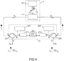
- Another configuration consists of bi-directional pumping illustrated in figure 4 .
- Two pump laser diodes 221 and 222 and thus two multiplexers 211 and 212 may be used depending on the length of fiber used, to ensure uniform pumping over its entire length; in this case, a diode is placed at each end of the fiber.
- a co-directional pumping fiber amplifier has an optimized noise factor, and in counter-directional pumping, a high output power.
- Two optical circulators 231 and 232 are also used.
- Bi-directional pumping can take advantage of both these advantages simultaneously.
- the optical pumping scheme is to be optimized for each bi-frequency laser architecture implemented, so as to maximize the optical powers of the 1.5 ⁇ m laser waves generated.
- the source device represented on the figure 3 , is composed of a continuous single-frequency laser emitting around 1.5 ⁇ m linearly polarized and an optical coupler allowing to separate the beam emitted in two beams (waves O 1 and O 1 ' ) distinct, but of the same state of polarization rectilinear, and mutually consistent. It is possible to use a non-polarized laser associated with a fiber bias controller 12 (as illustrated in FIG. figure 4 ), device for obtaining the desired polarization from any state of polarization.
- the principle of the invention has been illustrated by an example using an erbium doped fiber.
- this amplifier can be replaced by any other type of amplifying fiber.
- the two-wave mix for the realization of a bi-frequency laser can be considered, more generally, within any fiber doped by rare earth ions.
- Such fibers are commercially available, they are doped ytterbium, neodymium, samarium or thulium, or co-doped erbium-ytterbium, thulium-holmium or erbium-ytterbium.
- the wavelengths of absorption (determining those of optical pumping) and of laser emission vary according to the amplifier used.
- the concentration of dopant used determines the shape and width of the gain profile of the amplifier.
- an erbium-doped fiber is often, more exactly, a Ge-doped Er-doped silica (SiO 2 ) fiber, ie Ge / SiO 2 : Er, but an Al / P / SiO 2 : Er doping makes it possible to obtain a spectrum of gain all the more wide and flat that the concentration of aluminum is high.
- the optical pumping described above is performed by a laser diode at 980 nm.
- Other pump lasers may be used in the case of doping the amplifying fiber with a rare earth ion different from erbium. Note that even in the case of an erbium doped fiber, it is possible to use other absorption transitions (around 810 nm or 1480 nm). However, 980 nm and 1480 nm are the two most suitable wavelengths: semiconductor laser diodes are available at these wavelengths (in AlGaAs for 980 nm and InGaAsP for 1480 nm).
- erbium doped fiber amplifiers are transposed to the case of the present invention: a 980 nm pumping allows an almost total population inversion and an optimum signal-to-noise ratio, pumping at 1480 nm allows higher pumping and saturation powers (thus more gain).
- the 980 nm laser beam is coupled into the core of the doped fiber via a fiber-wavelength multiplexer.
- optical pumping architectures are possible, we will give some examples. Note however that these are methods typically reserved for high power fiber amplifiers, in which it is necessary to inject very intense pump beams (power laser diodes or laser diode arrays) without damage the core of the fiber.
- the first possibility is to use doped fibers having two concentric sheaths or several hearts. In this case, the pump wave is coupled in the additional sheath or in an additional core of sufficiently large area to prevent damage.
- a second possibility is the use of a doped fiber whose sheath is dug in V ("V-groove").
- the pump is then injected by the edge of the fiber and it propagates by reflections within the sheath, crossing the doped core at each reflection as described in the patent.
- US Patent 6,529,657 "Angle selective side-pumping of fiber amplifiers and lasers", L. Goldberg (Fairfax, VA), M. LeFlohic (Saint Quey Perros, FR), Keopsys Inc. (Fairfax, VA). March 4, 2003.
- the laser source (at 1.5 ⁇ m) is a diode pumped solid state laser with a very fine spectral width, so that the interfering waves in the fiber are coherent throughout their lifetime. spread.
- the maximum length of the amplifying fiber used in the context of the present invention is of the order of that of the fiber amplifiers is about twenty meters.
- a coherent laser source over 20 m, thus having a spectral width close to 15 MHz, (commercial DFB type diode laser diodes typically) is of sufficient quality to obtain dual-frequency operation.
- a dual-frequency laser architecture, injected by a single end of the fiber is represented on the figure 5 .
- the gain network is created by the interference between the wave O 1 , originating from the source laser, and the reflection of the wave O ' on a mirror 24 (of reflection coefficient R) placed at the other end of the doped fiber.
- the mirror may be either the end of the fiber ("cleavée” at the desired angle depending on the desired reflection), or a component (Bragg mirror or metal) connected or soldered at the end of fiber.
- this architecture allows the economy of components (coupler and isolator or circulator) and has the advantage of being highly insensitive to phase variations experienced by the wave before its injection into the amplifier.
- the resulting bi-frequency laser is then of the type shown on the figure 6 .
- the fiber section on which is inscribed the fixed network 201 may be either the end of the polarization-maintaining doped fiber, or a section of polarization-maintaining standard fiber which the values of the ordinary and extraordinary indices coincide perfectly with those of the doped fiber.
- the dynamic network originates in the doped fiber with the phase-matching conditions imposed by the presence of the fixed Bragg mirror.
- the advantage of this configuration is that only a pumping diode is necessary for the operation of the dual-frequency laser, the injection source at 1.5 microns is suppressed.
- the device functions as a DFB laser of great length (possibly of the order of a few meters), a promising component in terms of laser gain and spectral selectivity and whose manufacture by UV inscription is unthinkable.
Landscapes
- Physics & Mathematics (AREA)
- Electromagnetism (AREA)
- Engineering & Computer Science (AREA)
- Plasma & Fusion (AREA)
- Optics & Photonics (AREA)
- Lasers (AREA)
- Optical Communication System (AREA)
Description
- L'invention se rapporte à des lasers bi-fréquences « tout-fibre » comportant le mélange à deux ondes dans des fibres optiques amplificatrices à maintien de polarisation. Chacune des deux fréquences optiques obtenues se propage en polarisation rectiligne selon l'un des axes propres de la fibre.
- De tels lasers ont pour but de répondre au besoin en sources micro-ondes de très grande pureté spectrale, nécessaires dans les générations futures de systèmes radar, mais aussi de façon plus générale, pour la distribution de références de fréquence dans les systèmes complexes et dans des capteurs fibrés.
- Comme ce fut le cas dans les systèmes de télécommunication, l'optique se substitue aujourd'hui progressivement aux liaisons par câbles coaxiaux dans les systèmes radar. En effet, outre leurs moindres poids, encombrement, coût et leur insensibilité aux perturbations électromagnétiques, les fibres optiques présentent sur le câble coaxial les avantages fondamentaux suivants : leurs pertes sont faibles (0,3 dB/km contre 1000 dB/km pour les câbles), et leur dispersion est négligeable sur une large bande-passante hyperfréquence (une porteuse optique, de fréquence avoisinant 100 THz, peut être modulée sur une plage de 20 à 40 GHz sans limites dues à la dispersion chromatique de la fibre, la bande-passante d'un câble ne dépassant pas quelques GHz).
- Ainsi, certaines fonctions réalisées totalement dans le domaine électrique tendent aujourd'hui à faire appel à des technologies photoniques. Par exemple, tandis que les synthétiseurs actuels délivrent des signaux micro-ondes par mélanges successifs de fréquences électriques plus faibles, dégradant le rapport signal à bruit à chaque multiplication, la génération d'ondes hyperfréquence grâce au mélange hétérodyne de deux fréquences optiques autour de 1550 nm peut répondre aux besoins d'oscillateurs locaux de grande pureté spectrale dans les futurs radars optiques. Pour ce type d'application, il est nécessaire que le battement ait une largeur spectrale inférieure au kHz et que le bruit de phase environnant soit de l'ordre de - 130 dBc/Hz à 10 kHz de la fréquence centrale du signal [l'unité dBc signifie decibels par rapport à la porteuse (decibels relative to the carrier en anglais) et représente le rapport (en décibels) de puissance d'un signal par rapport à sa porteuse. L'unité dB est considérée comme unité SI, mais peut être remplacer par 10xlog10(puissance signal/ puissance porteuse]. Plusieurs techniques ont d'ores et déjà été proposées dans le but de réaliser des lasers bi-fréquence capables de générer de tels signaux micro-onde.
- Une première méthode consiste en l'utilisation de diodes laser bi-fréquence ou de deux diodes laser couplées comme décrit dans les références suivantes : T. Hidaka, S. Matsuura, M. Tani et K. Sakai, « CW terahertz wave generation by photomixing using a two-longitudinal mode laser diode », Electron. Lett. Vol. 33, 2039 (1997), M.D. Pelusi, HF Liu et D. Novak, « THz optical beat frequency generation from a single mode locked semiconductor laser », Appl. Phys. Lett. Vol. 71, 449 (1997),X. Wang, W. Mao, M. Al-Mumin, S. A. Pappert, J. Hong et G. Li, "Optical generation of microwave/millimeter-wave signals using two-section gain-coupled DFB lasers", IEEE Phot. Tech. Lett. Vol. 11, No. 10, 1292 (1999).
- Les avantages de ces sources sont leur compacité et leur grande accordabilité, puisqu'elles permettent de générer des signaux micro-onde de fréquence ajustable sur plusieurs dizaines de GHz. Cependant il est difficile d'obtenir une largeur spectrale suffisante en utilisant des diodes laser ; en effet, la qualité spectrale du battement obtenu reste insuffisante au regard des exigences du radar, sa largeur à mi-hauteur étant typiquement de l'ordre de la dizaine de MHz.
- D'autres techniques mettent à profit les propriétés de lasers solides et sont notamment décrits dans les références suivantes : M. Alouini, B. Benazet, M. Vallet, M. Brunel, P. Di Bin, F. Bretenaker, A. Le Floch et P. Thony, "Offset phase locking of Er: Yb: Glass Laser eigenstates for RF Photonics applications", IEEE Phot. Tech. Lett. Vol. 13, No. 4, 367 (2001), A.J.C. Vieira, P.R. Herczfeld, A. Rosen, M. Ermold, E.E. Funk, W.D. Jemison et K.J. Williams, « A mode-locked microchip laser optical transmitter for fiber radio », IEEE TTTM, Vol. 49, No. 10, 1882 (2001), L. Morvan, D. Dolfi, J.-P. Huignard, S. Blanc, M. Brunel, M. Vallet, F. Bretenaker et A. Le Floch, « Dual-frequency laser at 1.53 µm for generating high-purity optically carried microwave signals up to 20 GHz », CLEO 2004.
- De tels lasers sont extrêmement compacts et le battement hyperfréquence obtenu présente d'excellentes caractéristiques spectrales : la largeur spectrale peut être inférieure au kHz et le niveau de bruit de phase au pied du signal répond parfaitement aux exigences radar (jusqu'à - 130 dBc/Hz à 20 kHz de la porteuse hyperfréquence). De plus, l'accordabilité du signal micro-onde généré s'étend sur quelques GHz. Ces sources répondent aux besoins des futurs radars, leur unique point faible réside en la nécessité de boucles de contrôle opto-électronique de verrouillage de phase, assurant la stabilité en fréquence du battement micro-onde.
- Certaines solutions visant à utiliser des dispositifs tout-fibre mettent déjà en oeuvre des fibres optiques dopées pour réaliser des lasers bi-fréquence. W.H. Loh, J.P. de Sandro, G.J. Cowle, B.N. Samson et A.D. Ellis, «40 GHz optical-millimetre wave generation with dual polarisation distributed feedback fibre laser », Electr. Lett., Vol. 33, No. 7, 594 (1997), S.V. Chernikov, R. Kashyap, P.F. McKee, J.R. Taylor, « Dual frequency all fibre grating laser source », Electr. Lett. Vol. 29, No. 12, 1089 (1993), S. Li, H. Ding et K.T. Chan, « Erbium-doped fibre lasers for dual wavelength operation », Electr. Lett. Vol. 33, No. 1, 52 (1997), décrivent des dispositifs dans lesquels des réseaux de Bragg photo-inscrits dans des fibres optiques sont utilisés comme miroirs dans des lasers à fibre dopée erbium, pour atteindre un fonctionnement bi-fréquence. Il est possible, par ces dispositifs, de générer des battements hyperfréquence dont la largeur peut être inférieure au kHz, leur accordabilité restant toutefois limitée. Ces lasers sont sujets aux instabilités inhérentes à la propagation dans les fibres, à savoir notamment des variations de la phase optique accumulée et qui affectent directement la phase du signal hyperfréquence généré ultérieurement (conséquentes aux variations thermiques ou aux contraintes subies par la fibre).
- S. J. Frisken "Transient Bragg reflection gratings in erbium-doped fiber amplifiers", Optics Letters Vol. 17, no 24, 15.12.1992 décrit un filtre avec amplification formé par une source laser DFB émettant une onde optique principale à 1535,9 nm, qui est polarisée par un polarisateur, et un coupleur 50:50 pour diviser ladite onde principale polarisée en deux ondes optiques qui interférent dans une fibre dopée à l'erbium. Selon l'invention il est proposé une nouvelle approche de laser bi-fréquence fibré dans lequel le réseau de Bragg photo-inscrit utilisé dans les références précédentes, est un réseau holographique, dynamique, automatiquement adapté aux ondes en présence. Le processus optique mis en jeu est un effet non linéaire de couplage entre deux ondes inscrivant elles-même leur réseau de diffraction, par l'intermédiaire d'un hologramme de gain dans le milieu amplificateur.
- Plus précisément, l'invention a pour objet un laser bi-fréquence fibré comportant une source optique émettant au moins une onde optique principale à une première longueur d'onde, un milieu amplificateur fibré caractérisé en ce qu'il comporte des moyens pour faire interférer deux ondes optiques primaires issues de l'onde optique principale de manière à créer un réseau de diffraction au sein dudit milieu amplificateur, l'onde optique principale étant ainsi diffractée par ledit réseau de diffraction créé, en une seconde onde optique émettant à une seconde longueur d'onde.
- Selon une variante de l'invention, le milieu amplificateur comporte une fibre dopée à maintien de polarisation.
- Selon une variante de l'invention, le laser bi-fréquence comporte un coupleur permettant de créer les deux ondes optiques primaires à partir de l'onde optique principale.
- Selon une variante de l'invention, le milieu amplificateur fibré comporte un circulateur optique.
- Selon une variante de l'invention, le milieu amplificateur comporte une fibre optique, une pompe optique et un multiplexeur en longueur d'onde.
- Selon une variante, le milieu amplificateur comporte une fibre optique dopée possédant deux gaines concentriques ou plusieurs coeurs.
- Selon une variante de l'invention, le laser bi-fréquence comporte un circulateur sur le trajet de chacune des ondes optiques primaires, de manière à récupérer en sortie dudit laser bi-fréquence, deux ondes optiques secondaires.
- Selon une variante de l'invention, le milieu amplificateur comporte une fibre optique, deux pompes optiques et deux multiplexeurs en longueur d'onde.
- Selon une variante de l'invention, le laser bi-fréquence comporte des moyens de réflexion de ladite onde principale de manière à créer le réseau de diffraction par interférence entre ladite onde optique principale et l'onde réfléchie de ladite onde optique principale.
- Les moyens de réflexion peuvent comporter un composant de type miroir de Bragg ou miroir métallique.
- Les moyens de réflexion peuvent également comporter une fibre optique intégrant une extrémité réflectrice vis à vis de l'onde optique principale.
- L'invention sera mieux comprise et d'autres avantages apparaîtront à la lecture de la description qui va suivre et des figures annexées parmi lesquelles :
- les
figure 1a, 1b et 1c schématisent les étapes du processus physique de mélange à deux ondes dans un milieu amplificateur ; - la
figure 2 illustre la génération de l'onde secondaire au sein du réseau de diffraction créé dans le laser bi-fréquence de l'invention ; - la
figure 3 illustre un premier exemple de réalisation de laser bi-fréquence selon l'invention ; - la
figure 4 illustre un second exemple de laser bi-fréquence selon l'invention ; - la
figure 5 illustre un troisième exemple de laser bi-fréquence selon l'invention ; - la
figure 6 illustre une variante de l'invention dans laquelle une fibre incorpore un réseau. - De manière générale, le milieu amplificateur considéré dans le cadre de cette invention est une fibre optique dopée, à maintien de polarisation, préalablement placée en inversion de population. Le réseau de diffraction créé étant, par essence, adapté aux ondes optiques générées, la stabilité spectrale du battement hyperfréquence généré est garantie. Les ondes optiques voyageant dans le même milieu et subissant les mêmes perturbations, leur battement laisse présager d'une excellente pureté spectrale. La fréquence du signal micro-onde obtenu est susceptible d'être contrôlée par contraintes appliquées sur la fibre, ou par accordabilité en longueur d'onde de la source laser d'excitation, sans effet néfaste sur sa stabilité.
- L'invention consiste à provoquer du mélange d'onde, entre deux ondes de fréquence optique dites primaires à la fréquence v 1, au sein d'une fibre optique amplificatrice à maintien de polarisation, afin d'y générer une onde de fréquence optique dite secondaire à une fréquence v 2 ≠ v 1. Ce type de mélange d'ondes est notamment décrit dans les articles suivants : A. Brignon, G. Feugnet, J.-P. Huignard, and J.-P. Pocholle, "Efficient degenerate four-wave mixing in a diode-pumped microchip Nd:YV04 amplifier", Opt. Lett. Vol. 20, No. 6, 548-550 (1995), P. Yeh, « Two-wave mixing in nonlinear media », IEEE. J. Quantum Electr. Vol. 25, No. 3, 484-518 (1989), S.T. Fisken, «Transient Bragg Reflection gratings in erbium-doped fiber amplifiers »,Opt. Lett. Vol. 17, No. 24, 1776-1778 (1992), B. Fischer, J.L. Zyskind, J.W. Sulhoff and D.J. DiGiovanni, « Nonlinear wave mixing and induced gratings in erbium-doped fiber amplifiers » , Opt. Lett. Vol. 18, No. 24, 2108-2110 (1993).
- Les
figures 1a, 1b et 1c schématisent les étapes du processus physique de mélange à deux ondes dans un milieu amplificateur. Le milieu amplificateur est ici une fibre optique dopée FOP préalablement pompée optiquement par des moyens de pompage P, pour atteindre l'inversion de population entre ses niveaux d'énergie, notés N1 et N2 (figure 1a) . Considérons comme représenté enfigure 1b , deux ondes optiques de même fréquence

- Le principe de l'invention repose sur les considérations illustrée en
figure 2 , dans laquelle le milieu d'interaction est une fibre amplificatrice à maintien de polarisation, c'est-à-dire fortement biréfringente. - Considérant
e 1 ete 2 les deux axes propres, d'indices de réfraction respectifs ne et no , les deux ondes à la fréquence v 1 étant polarisées selon l'axee1 , leur couplage dans le milieu amplificateur génère un réseau de gain cohérent sur toute la longueur de la fibre. Ce dispositif peut être considéré comme une cavité laser DFB (distributed feed-back) injectée à la fréquence v 1. Certains des photons d'émission spontanée amplifiée polarisés selon l'axee 2 peuvent être à l'origine d'une onde oscillant dans cette cavité. Celle-ci doit vérifier les conditions d'accord de phase du DFB. Il s'agit de l'onde O2 (et l'onde O2') considérées ci-après. L'indice de réfraction vu par cette onde est no ≠ ne, par conséquent sa longueur d'onde d'accord λ 2 au réseau DFB diffère de λ 1 (et sa fréquence optique


- Cette onde profite du gain moyen du milieu amplificateur, ce qui laisse présager des intensités de sortie satisfaisantes.
- A partir des ondes O1 et O2, le battement entre v 1 et v 2 (obtenu par détection quadratique sur une photodiode rapide) peut être utilisé comme oscillateur local dans les futurs radars. En effet, une fibre du commerce, dont la biréfringence Δn=ne-no se situe dans la gamme Δn≈10-3-10-4, provoque une séparation Δλ=λ 1-λ 2 entre les deux longueurs d'ondes générées de l'ordre de Δλ≈0,1-1nm ; soit un écart de fréquence Δv=v 1 -v 2 se situant dans la fenêtre

- Par ailleurs ce type de source de signaux micro-ondes à la fréquence Δv est accordable. L'accordabilité peut être obtenue, soit en ajustant la valeur de la longueur d'onde d'injection λ 1, soit en contrôlant la valeur de la biréfringence Δn (et ce par des contraintes thermiques ou mécaniques sur la fibre). On peut considérer en première approximation, que la dilatation du réseau, c'est-à-dire la variation de son pas A en fonction de la température peut être négligée devant la dépendance de la biréfringence avec la température. La contribution dominante de la température est alors une variation de biréfringence de l'ordre de

- De plus, le dispositif présenté dans le cadre de cette invention est susceptible de présenter d'excellentes caractéristiques en terme de pureté spectrale. En effet, toute perturbation sur l'onde à la fréquence v 1 est subie à l'identique par l'onde à la fréquence v 2, pourvu que son temps caractéristique soit supérieur au temps de vie des atomes excités du milieu amplificateur. Ainsi les variations de phase dues par exemple aux variations de longueur de la fibre (fluctuations thermiques), ou bien encore à la source optique fournissant les ondes O1 et O1', sont intégrées par le réseau de gain.
- Différents exemples de réalisation sont décrits ci-après :
- Un premier exemple de réalisation de laser bi-fréquence fibré est illustré en
figure 3 . - Le milieu actif est une fibre optique à maintien de polarisation dopée erbium, 20. Celle-ci est pompée par une diode laser fibrée à 980 nm, 22, injectée dans la fibre par l'intermédiaire d'un multiplexeur en longueur d'onde 21. Le pompage tel qu'il est représenté sur la
figure 3 est co-directionnel : la pompe à 980 nm voyage dans le même sens que l'onde O1 injectée à 1,5 µm. Notons qu'il est possible d'utiliser un pompage contra-directionnel. L'ensemble constitue le milieu amplificateur 2. - Selon cet exemple, le dispositif source 1, est composé d'un laser continu monofréquence 10 émettant autour de 1,5 µm polarisé rectilignement et d'un coupleur optique 11 permettant de séparer le faisceau émis en deux faisceaux (ondes O1 et O1') distincts, mais de même état de polarisation rectiligne, et cohérents mutuellement.
- Les ondes O1 et O1' sont injectées dans l'amplificateur 2. Sur le schéma de base de la
figure 3 , l'onde O1 traverse un circulateur optique 23 du point A au point B, avant son injection dans la fibre amplificatrice après passage dans le multiplexeur 21. Aucun retour n'est possible du point B vers le point A. Les ondes O1' (ayant traversé la fibre et interféré avec l'onde O1) et O2 (diffractée et amplifiée à partir du bruit dans la fibre) traversent le circulateur optique du point B au point C où elles sont disponibles pour générer le battement micro-onde recherché. L'isolateur 3 empêche le passage de l'onde O1 amplifiée vers le dispositif source. - Une autre configuration consiste en un pompage bi-directionnel illustré en
figure 4 . Deux diodes laser de pompage 221 et 222 et donc deux multiplexeurs 211 et 212 peuvent être utilisés suivant la longueur de fibre 20 utilisée, pour garantir un pompage uniforme sur toute sa longueur; dans ce cas, une diode est placée à chaque extrémité de la fibre. En règle générale, un amplificateur à fibre en pompage co-directionnel possède un facteur de bruit optimisé, et en pompage contra-directionnel, une puissance de sortie élevée. Deux circulateurs optiques 231 et 232 sont également utilisés. Un pompage bi-directionnel peut ainsi tirer parti simultanément de ces deux avantages. Le schéma du pompage optique est à optimiser pour chaque architecture de laser bi-fréquence mise en oeuvre, de façon à maximiser les puissances optiques des ondes laser à 1,5 µm générées. - Il est à noter que le dispositif source, représenté sur la
figure 3 , est composé d'un laser continu monofréquence émettant autour de 1,5 µm polarisé rectilignement et d'un coupleur optique permettant de séparer le faisceau émis en deux faisceaux (ondes O1 et O1') distincts, mais de même état de polarisation rectiligne, et cohérents mutuellement. Il est possible d'utiliser un laser non-polarisé associé à un contrôleur de polarisation 12 fibré (comme illustré enfigure 4 ), dispositif permettant d'obtenir la polarisation désirée à partir d'un état de polarisation quelconque. - Selon cette variante, il est possible de disposer de deux sorties (points C et C'), en utilisant deux circulateurs optiques et les ondes O2 et O2' diffractées dans les deux directions dans la fibre.
- Le principe de l'invention a été illustré par un exemple utilisant une fibre dopée erbium. Notons que cet amplificateur peut être remplacé par tout autre type de fibre amplificatrice. En effet, le mélange à deux ondes pour la réalisation d'un laser bi-fréquence peut être envisagé, de manière plus générale, au sein de toute fibre dopée par des ions terre-rare. De telles fibres se trouvent dans le commerce, elles sont dopées ytterbium, néodyme, samarium ou thulium, ou encore co-dopée erbium-ytterbium, thulium-holmium ou erbium-ytterbium. Bien sûr les longueurs d'onde d'absorption (déterminant celles du pompage optique) et d'émission laser varient selon l'amplificateur utilisé. De plus, la concentration du dopant utilisé détermine la forme et la largeur du profil de gain de l'amplificateur. Ainsi par exemple, une fibre dopée erbium est souvent, plus exactement une fibre en silice (SiO2) dopée Ge et dopée Er, i.e Ge/SiO2:Er, mais un dopage Al/P/SiO2:Er permet d'obtenir un spectre de gain d'autant plus large et plat que la concentration en aluminium est élevée.
- Le pompage optique décrit précédemment est effectué par une diode laser à 980 nm. D'autres lasers de pompe peuvent être utilisés dans le cas d'un dopage de la fibre amplificatrice par un ion terre-rare différent de l'erbium. Notons que même dans le cas d'une fibre dopée erbium, il est envisageable d'utiliser d'autres transitions d'absorption (autour de 810 nm ou de 1480 nm). Cependant 980 nm et 1480 nm sont les deux longueurs d'onde les mieux adaptées : des diodes lasers à semi-conducteur sont disponibles à ces longueurs d'onde (en AlGaAs pour 980 nm et en InGaAsP pour 1480 nm). Par ailleurs, il est à prévoir que les propriétés des amplificateurs à fibre dopée erbium soient transposées au cas de la présente invention : un pompage à 980 nm permet une inversion de population quasi totale et un rapport signal sur bruit optimum, un pompage à 1480 nm permet des puissances de pompage et de saturation plus élevées (donc plus de gain).
- Dans les exemples de réalisation décrit ci-dessus, le faisceau laser à 980 nm est couplé dans le coeur de la fibre dopée, par l'intermédiaire d'un multiplexeur en longueurs d'onde fibré.
- D'autres architectures de pompage optique sont possibles, nous allons en donner quelques exemples. Notons toutefois qu'il s'agit de méthodes typiquement réservées aux amplificateurs à fibre de forte puissance, dans lesquels il est nécessaire d'injecter des faisceaux pompes très intenses (diodes lasers de puissance ou barrettes de diodes laser) sans endommager le coeur de la fibre. La première possibilité est d'utiliser des fibres dopées possédant deux gaines concentriques ou bien plusieurs coeurs. Dans ce cas, l'onde de pompe est couplée dans la gaine supplémentaire ou dans un coeur supplémentaire, d'aire suffisamment grande pour éviter tout dommage.
- Une seconde possibilité est l'utilisation d'une fibre dopée dont la gaine est creusée en V (« V-groove »). La pompe est alors injectée par la tranche de la fibre et elle se propage par réflexions au sein de la gaine, croisant le coeur dopé à chaque réflexion comme décrit dans le brevet
US Patent 6,529,657 : « Angle selective side-pumping of fiber amplifiers and lasers », L. Goldberg (Fairfax, VA), M. LeFlohic (Saint Quey Perros, FR), Keopsys Inc. (Fairfax, VA). March 4, 2003. - Dans l'architecture type de la présente invention, la source laser (à 1,5 µm) est un laser état solide pompé par diode, de largeur spectrale très fine, afin que les ondes interférant dans la fibre soient cohérentes tout au long de leur propagation. La longueur maximale de la fibre amplificatrice utilisée dans le cadre de la présente invention est de l'ordre de celle des amplificateurs à fibre soit une vingtaine de mètres. Une source laser cohérente sur 20 m, possédant donc une largeur spectrale voisine de 15 MHz, (diodes lasers à semi-conducteur type DFB du commerce typiquement) est de qualité suffisante pour obtenir le fonctionnement bi-fréquence.
- Une architecture de laser bi-fréquence, injecté par une seule extrémité de la fibre est représentée sur la
figure 5 . Dans cette configuration, le réseau de gain est créé par l'interférence entre l'onde O1, provenant du laser source, et la réflexion de l'onde O1' sur un miroir 24 (de coefficient de réflexion R) placé à l'autre extrémité de la fibre dopée. Le miroir peut être soit l'extrémité même de la fibre (« cleavée » à l'angle souhaité en fonction de la réflexion désirée), soit un composant (miroir de Bragg ou métallique) connecté ou soudé en bout de fibre. - Pour une valeur g0 (gain petit signal de l'amplificateur) fixée, l'efficacité du réseau de gain est directement liée au rapport des puissances entre les ondes interférant (aux pertes du multiplexeur près) : PB'/PB=Reg0L (PB : puissance injectée au point B; PB' : puissance de l'onde réfléchie au point B').
- Outre sa simplicité de mise en oeuvre, cette architecture permet l'économie de composants (coupleur et isolateur ou circulateur) et présente l'avantage d'être fortement insensible aux variations de phase subies par l'onde avant son injection dans l'amplificateur.
- Il est possible de combiner le réseau de gain dynamique (par mélange d'ondes dans la fibre amplificatrice), avec l'inscription d'un miroir de Bragg fixe (par des techniques UV standards).
- Le laser bi-fréquence résultant est alors du type de celui présenté sur la
figure 6 . La section de fibre sur laquelle est inscrit le réseau fixe 201 (de l'ordre de quelques centimètres de long) peut-être soit l'extrémité de la fibre dopée à maintien de polarisation, soit un tronçon de fibre standard à maintien de polarisation dont les valeurs des indices ordinaire et extraordinaire coïncident parfaitement avec ceux de la fibre dopée. Le réseau dynamique prend naissance dans la fibre dopée avec les conditions d'accord de phase imposées par la présence du miroir de Bragg fixe. - L'avantage de cette configuration est que seule une diode de pompage est nécessaire au fonctionnement du laser bi-fréquence, la source d'injection à 1,5 µm est supprimée. Le dispositif fonctionne comme un laser DFB de grande longueur (éventuellement de l'ordre de quelques mètres), composant prometteur en terme de gain laser et de sélectivité spectrale et dont la fabrication par inscription UV est inenvisageable.
- Notons que dans cette configuration il ne paraît pas exclus de supprimer également le multiplexeur, en pompant dans un sens et en collectant le signal laser à 1,5 µm dans le sens opposé.
Claims (9)
- Laser bi-fréquence fibré comportant une source optique laser (1) émettant au moins une onde optique polarisée principale à une première longueur d'onde (λ 1),
un milieu amplificateur fibré (2), et
des moyens pour faire interférer (11, 24, 201) deux ondes optiques primaires (O1,O1') issues de l'onde optique polarisée principale, les deux ondes optiques primaires étant :∘ de même fréquence optique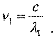 ∘ de même état de polarisation, ledit état étant polarisé selon un axe propre
e 1,e 1 ete 2 étant les deux axes propres, des indices de réfraction respectifs ne et no de la fibre optique dopée- ledit milieu amplificateur comportant une fibre optique dopée, à maintien de polarisation et préalablement pompée optiquement pour atteindre une inversion de population entre deux niveaux d'énergie, ladite fibre étant fortement biréfringente de biréfringence Δn = ne-no;- le couplage des deux ondes optiques primaires dans le milieu amplificateur créant un réseau de diffraction au sein dudit milieu amplificateur fibré, et ansi un réseau de gain cohérent sur toute la longueur de la fibre et une cavité laser DFB à la fréquence v 2 selon l'axe de la fibre correspondent à l'indice de réfraction no, la cavité laser DFB étant injectée à la fréquence v 1,- certains des photons d'émission spontanée amplifiée polarisés selon l'axee 2 étant à l'origine d'une seconde onde oscillante (O2, O2') à la fréquence optique v 2 correspondant à la longueur d' onde λ2 et définie par l'équation suivante :
le pas du réseau répondant aux deux équations : - ledit laser bi-fréquence émettant en sortie dudit milieu amplificateur aux fréquences optiques v 1 et v 2, et
ledit laser bi-fréquence fibré comprenant: un circulateur optique (23) qui est traversé par une des deux ondes optiques primaires (O1') et par la seconde onde oscillante (O2), de façon à générer le battement entre lesdites ondes (O1', O2) de fréquence v 1 et v 2. - Laser bi-fréquence fibré selon la revendication 1, caractérisé en ce qu'il comporte un coupleur permettant de créer les deux ondes optiques primaires à partir de la onde optique principale (O1, O1').
- Laser bi-fréquence fibré selon l'une des revendications 1 à 2, caractérisé en ce que le milieu amplificateur (2) comporte une fibre optique (20), une pompe optique (22) et un multiplexeur en longueur d'onde (21).
- Laser bi-fréquence fibré selon l'une des revendications 1 à 3, caractérisé en ce que le milieu amplificateur (2) comporte une fibre optique dopée possédant deux gaines concentriques ou plusieurs coeurs.
- Laser bi-fréquence fibré selon l'une des revendications 1 à 3, caractérisé en ce qu'il comporte sur le trajet de chacune des ondes optiques primaires un circulateur (231, 232), de manière à récupérer en sortie dudit laser bi-fréquence, deux ondes optiques secondaires (O2, O2').
- Laser bi-fréquence fibré selon la revendication 4, caractérisé en ce que le milieu amplificateur (2) comporte une fibre optique (20), deux pompes optiques (221, 222) et deux multiplexeurs en longueur d'onde (211, 212).
- Laser bi-fréquence fibré selon la revendication 1, caractérisé en ce qu'il comporte des moyens de réflexion (24) de ladite onde principale de manière à créer le réseau de diffraction par interférence entre ladite onde optique principale et l'onde réfléchie de ladite onde optique principale.
- Laser bi-fréquence fibré selon la revendication 7, caractérisé en ce que les moyens de réflexion comportent un composant de type miroir de Bragg, fibré ou pas, ou miroir métallique.
- Laser bi-fréquence fibré selon la revendication 6, caractérisé en ce que le milieu amplificateur comporte une fibre optique intégrant une extrémité réflectrice (201) vis à vis de l'onde optique principale.
Applications Claiming Priority (2)
| Application Number | Priority Date | Filing Date | Title |
|---|---|---|---|
| FR0705379A FR2919439B1 (fr) | 2007-07-24 | 2007-07-24 | Laser bi-frequence fibre par melange d'ondes dans des fibres optiques amplificatrices |
| PCT/EP2008/059611 WO2009013294A1 (fr) | 2007-07-24 | 2008-07-22 | Laser bi-frequence fibre par melange d'ondes dans des fibres optiques amplificatrices |
Publications (2)
| Publication Number | Publication Date |
|---|---|
| EP2179326A1 EP2179326A1 (fr) | 2010-04-28 |
| EP2179326B1 true EP2179326B1 (fr) | 2017-09-27 |
Family
ID=39047534
Family Applications (1)
| Application Number | Title | Priority Date | Filing Date |
|---|---|---|---|
| EP08775283.8A Active EP2179326B1 (fr) | 2007-07-24 | 2008-07-22 | Laser bi-frequence fibre par melange d'ondes dans des fibres optiques amplificatrices |
Country Status (5)
| Country | Link |
|---|---|
| EP (1) | EP2179326B1 (fr) |
| ES (1) | ES2653196T3 (fr) |
| FR (1) | FR2919439B1 (fr) |
| NO (1) | NO2179326T3 (fr) |
| WO (1) | WO2009013294A1 (fr) |
Families Citing this family (3)
| Publication number | Priority date | Publication date | Assignee | Title |
|---|---|---|---|---|
| JP4530433B2 (ja) * | 1996-05-07 | 2010-08-25 | プリヴァ・ディー・ディー | 脂質及びグルコースの代謝疾患治療のための方法及び組成物 |
| CN112018591B (zh) * | 2020-08-24 | 2021-09-07 | 中国科学院上海光学精密机械研究所 | 基于双频光纤干涉仪稳频激光的超稳微波产生装置 |
| CN112003121B (zh) * | 2020-08-24 | 2021-11-30 | 中国科学院上海光学精密机械研究所 | 基于双频法布里珀罗腔稳频激光的超稳微波产生装置 |
Family Cites Families (1)
| Publication number | Priority date | Publication date | Assignee | Title |
|---|---|---|---|---|
| FR2867000A1 (fr) * | 2004-02-27 | 2005-09-02 | Thales Sa | Dispositif de reduction dynamique de la porteuse optique d'un signal module en hyperfrequence |
-
2007
- 2007-07-24 FR FR0705379A patent/FR2919439B1/fr not_active Expired - Fee Related
-
2008
- 2008-07-22 ES ES08775283.8T patent/ES2653196T3/es active Active
- 2008-07-22 WO PCT/EP2008/059611 patent/WO2009013294A1/fr not_active Ceased
- 2008-07-22 EP EP08775283.8A patent/EP2179326B1/fr active Active
- 2008-07-22 NO NO08775283A patent/NO2179326T3/no unknown
Non-Patent Citations (1)
| Title |
|---|
| FRISKEN S J: "TRANSIENT BRAGG REFLECTION GRATINGS IN ERBIUM-DOPED FIBER AMPLIFIERS", OPTICS LETTERS, OSA, OPTICAL SOCIETY OF AMERICA, WASHINGTON, DC, US, vol. 17, no. 24, 15 December 1992 (1992-12-15), pages 1776 - 1778, XP000334834, ISSN: 0146-9592 * |
Also Published As
| Publication number | Publication date |
|---|---|
| WO2009013294A1 (fr) | 2009-01-29 |
| NO2179326T3 (fr) | 2018-02-24 |
| FR2919439A1 (fr) | 2009-01-30 |
| ES2653196T3 (es) | 2018-02-06 |
| EP2179326A1 (fr) | 2010-04-28 |
| FR2919439B1 (fr) | 2009-09-04 |
Similar Documents
| Publication | Publication Date | Title |
|---|---|---|
| Churkin et al. | Recent advances in fundamentals and applications of random fiber lasers | |
| Laporta et al. | Erbium–ytterbium microlasers: optical properties and lasing characteristics | |
| Huang et al. | 3 kW narrow linewidth high spectral density continuous wave fiber laser based on fiber Bragg grating | |
| Zhao et al. | Research on a novel composite structure Er3+-doped DBR fiber laser with a π-phase shifted FBG | |
| Hunsperger | Photonic devices and systems | |
| KR20140026522A (ko) | 라만 분산 피드백 파이버 레이저 및 이를 사용한 고 출력 레이저 시스템 | |
| Shang et al. | Tunable narrow linewidth linear cavity fiber laser based on a one-way round-trip structure | |
| Nechepurenko et al. | Optimal defect position in a DFB fiber laser | |
| EP1125347B1 (fr) | Filtres auto-adaptes pour l'affinement de l'emission laser | |
| Lv et al. | Tunable single frequency Hz-magnitude narrow linewidth Brillouin fiber laser based on parity-time symmetry | |
| US20150043598A1 (en) | Method for generating optical pulses and optical pulse generator | |
| Wei et al. | Narrow linewidth 1064 nm laser diode with external distributed feedback | |
| Poozesh et al. | Single-frequency gain-switched ytterbium-doped fiber laser at 1017 nm based on dynamic self-induced grating in a saturable absorber | |
| FR2919439A1 (fr) | Laser bi-frequence fibre par melange d'ondes dans des fibres optiques amplificatrices | |
| Cai et al. | Continuous-wave THz difference frequency generation based on kHz-linewidth dual-wavelength single-longitudinal-mode Er-doped fiber laser and DAST organic crystal | |
| EP1397851A1 (fr) | Source laser stabilisee en frequence | |
| EP3469668B1 (fr) | Module d'affinement spectral, dispositif à raie spectrale affinée et procédé afférent | |
| Yeh et al. | Single-longitudinal-mode erbium-doped fiber laser with novel scheme utilizing fiber Bragg grating inside ring cavity | |
| Valley et al. | Modeling transient gain dynamics in a cladding-pumped Yb-doped fiber amplifier pulsed at low repetition rates | |
| Wei et al. | High-efficiency Brillouin random fiber laser based on dynamic fiber grating-incorporated half-open linear cavity | |
| Elashmawy et al. | Random DFB-FL using apodized FBG and DFB-FL optical filters: a numerical performance evaluation | |
| Wang et al. | Saturable absorber–based single-longitudinal mode tunable fiber laser using a Faraday rotator mirror as the rear cavity end | |
| Ooi et al. | High-power single-wavelength SOA-based fiber-ring laser with an optical modulator | |
| Li et al. | Wavelength-tunable passively Q-switched random fiber laser based on cascaded doped fiber segments and random phase-shifted Bragg grating | |
| Surrow et al. | Widely tunable SG-DBR laser with ultra-narrow linewidth achieved via polarization-controlled feedback |
Legal Events
| Date | Code | Title | Description |
|---|---|---|---|
| PUAI | Public reference made under article 153(3) epc to a published international application that has entered the european phase |
Free format text: ORIGINAL CODE: 0009012 |
|
| 17P | Request for examination filed |
Effective date: 20100121 |
|
| AK | Designated contracting states |
Kind code of ref document: A1 Designated state(s): AT BE BG CH CY CZ DE DK EE ES FI FR GB GR HR HU IE IS IT LI LT LU LV MC MT NL NO PL PT RO SE SI SK TR |
|
| AX | Request for extension of the european patent |
Extension state: AL BA MK RS |
|
| DAX | Request for extension of the european patent (deleted) | ||
| 17Q | First examination report despatched |
Effective date: 20110317 |
|
| REG | Reference to a national code |
Ref country code: DE Ref legal event code: R079 Ref document number: 602008052270 Country of ref document: DE Free format text: PREVIOUS MAIN CLASS: G02F0001390000 Ipc: H01S0003094100 |
|
| GRAP | Despatch of communication of intention to grant a patent |
Free format text: ORIGINAL CODE: EPIDOSNIGR1 |
|
| RIC1 | Information provided on ipc code assigned before grant |
Ipc: H01S 3/0941 20060101AFI20170309BHEP Ipc: H01S 3/067 20060101ALI20170309BHEP Ipc: H01S 3/16 20060101ALI20170309BHEP Ipc: H01S 3/08 20060101ALI20170309BHEP |
|
| INTG | Intention to grant announced |
Effective date: 20170329 |
|
| RIN1 | Information on inventor provided before grant (corrected) |
Inventor name: MOLIN, STEPHANIE Inventor name: MORVAN, LOIC Inventor name: DOLFI, DANIEL Inventor name: HUIGNARD, JEAN-PIERRE |
|
| GRAJ | Information related to disapproval of communication of intention to grant by the applicant or resumption of examination proceedings by the epo deleted |
Free format text: ORIGINAL CODE: EPIDOSDIGR1 |
|
| GRAS | Grant fee paid |
Free format text: ORIGINAL CODE: EPIDOSNIGR3 |
|
| GRAP | Despatch of communication of intention to grant a patent |
Free format text: ORIGINAL CODE: EPIDOSNIGR1 |
|
| INTC | Intention to grant announced (deleted) | ||
| GRAA | (expected) grant |
Free format text: ORIGINAL CODE: 0009210 |
|
| RAP1 | Party data changed (applicant data changed or rights of an application transferred) |
Owner name: THALES |
|
| INTG | Intention to grant announced |
Effective date: 20170817 |
|
| AK | Designated contracting states |
Kind code of ref document: B1 Designated state(s): AT BE BG CH CY CZ DE DK EE ES FI FR GB GR HR HU IE IS IT LI LT LU LV MC MT NL NO PL PT RO SE SI SK TR |
|
| REG | Reference to a national code |
Ref country code: GB Ref legal event code: FG4D Free format text: NOT ENGLISH |
|
| REG | Reference to a national code |
Ref country code: CH Ref legal event code: EP |
|
| REG | Reference to a national code |
Ref country code: AT Ref legal event code: REF Ref document number: 932836 Country of ref document: AT Kind code of ref document: T Effective date: 20171015 |
|
| REG | Reference to a national code |
Ref country code: IE Ref legal event code: FG4D Free format text: LANGUAGE OF EP DOCUMENT: FRENCH |
|
| REG | Reference to a national code |
Ref country code: DE Ref legal event code: R096 Ref document number: 602008052270 Country of ref document: DE |
|
| REG | Reference to a national code |
Ref country code: SE Ref legal event code: TRGR |
|
| REG | Reference to a national code |
Ref country code: NL Ref legal event code: FP |
|
| PG25 | Lapsed in a contracting state [announced via postgrant information from national office to epo] |
Ref country code: LT Free format text: LAPSE BECAUSE OF FAILURE TO SUBMIT A TRANSLATION OF THE DESCRIPTION OR TO PAY THE FEE WITHIN THE PRESCRIBED TIME-LIMIT Effective date: 20170927 Ref country code: HR Free format text: LAPSE BECAUSE OF FAILURE TO SUBMIT A TRANSLATION OF THE DESCRIPTION OR TO PAY THE FEE WITHIN THE PRESCRIBED TIME-LIMIT Effective date: 20170927 |
|
| REG | Reference to a national code |
Ref country code: ES Ref legal event code: FG2A Ref document number: 2653196 Country of ref document: ES Kind code of ref document: T3 Effective date: 20180206 |
|
| REG | Reference to a national code |
Ref country code: LT Ref legal event code: MG4D |
|
| REG | Reference to a national code |
Ref country code: AT Ref legal event code: MK05 Ref document number: 932836 Country of ref document: AT Kind code of ref document: T Effective date: 20170927 |
|
| REG | Reference to a national code |
Ref country code: NO Ref legal event code: T2 Effective date: 20170927 |
|
| PG25 | Lapsed in a contracting state [announced via postgrant information from national office to epo] |
Ref country code: BG Free format text: LAPSE BECAUSE OF FAILURE TO SUBMIT A TRANSLATION OF THE DESCRIPTION OR TO PAY THE FEE WITHIN THE PRESCRIBED TIME-LIMIT Effective date: 20171227 Ref country code: GR Free format text: LAPSE BECAUSE OF FAILURE TO SUBMIT A TRANSLATION OF THE DESCRIPTION OR TO PAY THE FEE WITHIN THE PRESCRIBED TIME-LIMIT Effective date: 20171228 Ref country code: LV Free format text: LAPSE BECAUSE OF FAILURE TO SUBMIT A TRANSLATION OF THE DESCRIPTION OR TO PAY THE FEE WITHIN THE PRESCRIBED TIME-LIMIT Effective date: 20170927 |
|
| PG25 | Lapsed in a contracting state [announced via postgrant information from national office to epo] |
Ref country code: RO Free format text: LAPSE BECAUSE OF FAILURE TO SUBMIT A TRANSLATION OF THE DESCRIPTION OR TO PAY THE FEE WITHIN THE PRESCRIBED TIME-LIMIT Effective date: 20170927 Ref country code: CZ Free format text: LAPSE BECAUSE OF FAILURE TO SUBMIT A TRANSLATION OF THE DESCRIPTION OR TO PAY THE FEE WITHIN THE PRESCRIBED TIME-LIMIT Effective date: 20170927 |
|
| PG25 | Lapsed in a contracting state [announced via postgrant information from national office to epo] |
Ref country code: IS Free format text: LAPSE BECAUSE OF FAILURE TO SUBMIT A TRANSLATION OF THE DESCRIPTION OR TO PAY THE FEE WITHIN THE PRESCRIBED TIME-LIMIT Effective date: 20180127 Ref country code: EE Free format text: LAPSE BECAUSE OF FAILURE TO SUBMIT A TRANSLATION OF THE DESCRIPTION OR TO PAY THE FEE WITHIN THE PRESCRIBED TIME-LIMIT Effective date: 20170927 Ref country code: SK Free format text: LAPSE BECAUSE OF FAILURE TO SUBMIT A TRANSLATION OF THE DESCRIPTION OR TO PAY THE FEE WITHIN THE PRESCRIBED TIME-LIMIT Effective date: 20170927 Ref country code: AT Free format text: LAPSE BECAUSE OF FAILURE TO SUBMIT A TRANSLATION OF THE DESCRIPTION OR TO PAY THE FEE WITHIN THE PRESCRIBED TIME-LIMIT Effective date: 20170927 |
|
| REG | Reference to a national code |
Ref country code: FR Ref legal event code: PLFP Year of fee payment: 11 Ref country code: DE Ref legal event code: R097 Ref document number: 602008052270 Country of ref document: DE |
|
| PG25 | Lapsed in a contracting state [announced via postgrant information from national office to epo] |
Ref country code: DK Free format text: LAPSE BECAUSE OF FAILURE TO SUBMIT A TRANSLATION OF THE DESCRIPTION OR TO PAY THE FEE WITHIN THE PRESCRIBED TIME-LIMIT Effective date: 20170927 |
|
| PLBE | No opposition filed within time limit |
Free format text: ORIGINAL CODE: 0009261 |
|
| STAA | Information on the status of an ep patent application or granted ep patent |
Free format text: STATUS: NO OPPOSITION FILED WITHIN TIME LIMIT |
|
| PG25 | Lapsed in a contracting state [announced via postgrant information from national office to epo] |
Ref country code: PL Free format text: LAPSE BECAUSE OF FAILURE TO SUBMIT A TRANSLATION OF THE DESCRIPTION OR TO PAY THE FEE WITHIN THE PRESCRIBED TIME-LIMIT Effective date: 20170927 |
|
| 26N | No opposition filed |
Effective date: 20180628 |
|
| PG25 | Lapsed in a contracting state [announced via postgrant information from national office to epo] |
Ref country code: MT Free format text: LAPSE BECAUSE OF FAILURE TO SUBMIT A TRANSLATION OF THE DESCRIPTION OR TO PAY THE FEE WITHIN THE PRESCRIBED TIME-LIMIT Effective date: 20170927 |
|
| PG25 | Lapsed in a contracting state [announced via postgrant information from national office to epo] |
Ref country code: SI Free format text: LAPSE BECAUSE OF FAILURE TO SUBMIT A TRANSLATION OF THE DESCRIPTION OR TO PAY THE FEE WITHIN THE PRESCRIBED TIME-LIMIT Effective date: 20170927 |
|
| REG | Reference to a national code |
Ref country code: CH Ref legal event code: PL |
|
| PG25 | Lapsed in a contracting state [announced via postgrant information from national office to epo] |
Ref country code: LU Free format text: LAPSE BECAUSE OF NON-PAYMENT OF DUE FEES Effective date: 20180722 Ref country code: MC Free format text: LAPSE BECAUSE OF FAILURE TO SUBMIT A TRANSLATION OF THE DESCRIPTION OR TO PAY THE FEE WITHIN THE PRESCRIBED TIME-LIMIT Effective date: 20170927 |
|
| REG | Reference to a national code |
Ref country code: BE Ref legal event code: MM Effective date: 20180731 |
|
| REG | Reference to a national code |
Ref country code: IE Ref legal event code: MM4A |
|
| PG25 | Lapsed in a contracting state [announced via postgrant information from national office to epo] |
Ref country code: IE Free format text: LAPSE BECAUSE OF NON-PAYMENT OF DUE FEES Effective date: 20180722 Ref country code: CH Free format text: LAPSE BECAUSE OF NON-PAYMENT OF DUE FEES Effective date: 20180731 Ref country code: LI Free format text: LAPSE BECAUSE OF NON-PAYMENT OF DUE FEES Effective date: 20180731 |
|
| PG25 | Lapsed in a contracting state [announced via postgrant information from national office to epo] |
Ref country code: BE Free format text: LAPSE BECAUSE OF NON-PAYMENT OF DUE FEES Effective date: 20180731 |
|
| PG25 | Lapsed in a contracting state [announced via postgrant information from national office to epo] |
Ref country code: TR Free format text: LAPSE BECAUSE OF FAILURE TO SUBMIT A TRANSLATION OF THE DESCRIPTION OR TO PAY THE FEE WITHIN THE PRESCRIBED TIME-LIMIT Effective date: 20170927 |
|
| PG25 | Lapsed in a contracting state [announced via postgrant information from national office to epo] |
Ref country code: HU Free format text: LAPSE BECAUSE OF FAILURE TO SUBMIT A TRANSLATION OF THE DESCRIPTION OR TO PAY THE FEE WITHIN THE PRESCRIBED TIME-LIMIT; INVALID AB INITIO Effective date: 20080722 Ref country code: PT Free format text: LAPSE BECAUSE OF FAILURE TO SUBMIT A TRANSLATION OF THE DESCRIPTION OR TO PAY THE FEE WITHIN THE PRESCRIBED TIME-LIMIT Effective date: 20170927 |
|
| PG25 | Lapsed in a contracting state [announced via postgrant information from national office to epo] |
Ref country code: CY Free format text: LAPSE BECAUSE OF FAILURE TO SUBMIT A TRANSLATION OF THE DESCRIPTION OR TO PAY THE FEE WITHIN THE PRESCRIBED TIME-LIMIT Effective date: 20170927 |
|
| P01 | Opt-out of the competence of the unified patent court (upc) registered |
Effective date: 20230529 |
|
| PGFP | Annual fee paid to national office [announced via postgrant information from national office to epo] |
Ref country code: FI Payment date: 20230712 Year of fee payment: 16 Ref country code: ES Payment date: 20230808 Year of fee payment: 16 |
|
| PGFP | Annual fee paid to national office [announced via postgrant information from national office to epo] |
Ref country code: GB Payment date: 20240613 Year of fee payment: 17 |
|
| PGFP | Annual fee paid to national office [announced via postgrant information from national office to epo] |
Ref country code: NL Payment date: 20240627 Year of fee payment: 17 |
|
| PGFP | Annual fee paid to national office [announced via postgrant information from national office to epo] |
Ref country code: FR Payment date: 20240621 Year of fee payment: 17 |
|
| PGFP | Annual fee paid to national office [announced via postgrant information from national office to epo] |
Ref country code: SE Payment date: 20240626 Year of fee payment: 17 |
|
| PGFP | Annual fee paid to national office [announced via postgrant information from national office to epo] |
Ref country code: IT Payment date: 20240627 Year of fee payment: 17 |
|
| PGFP | Annual fee paid to national office [announced via postgrant information from national office to epo] |
Ref country code: DE Payment date: 20240618 Year of fee payment: 17 |
|
| PGFP | Annual fee paid to national office [announced via postgrant information from national office to epo] |
Ref country code: NO Payment date: 20240709 Year of fee payment: 17 |
|
| PG25 | Lapsed in a contracting state [announced via postgrant information from national office to epo] |
Ref country code: FI Free format text: LAPSE BECAUSE OF NON-PAYMENT OF DUE FEES Effective date: 20240722 |
|
| REG | Reference to a national code |
Ref country code: ES Ref legal event code: FD2A Effective date: 20250829 |
|
| PG25 | Lapsed in a contracting state [announced via postgrant information from national office to epo] |
Ref country code: ES Free format text: LAPSE BECAUSE OF NON-PAYMENT OF DUE FEES Effective date: 20240723 |
|
| REG | Reference to a national code |
Ref country code: DE Ref legal event code: R119 Ref document number: 602008052270 Country of ref document: DE |
|
| REG | Reference to a national code |
Ref country code: NL Ref legal event code: MM Effective date: 20250801 |
|
| GBPC | Gb: european patent ceased through non-payment of renewal fee |
Effective date: 20250722 |
|
| PG25 | Lapsed in a contracting state [announced via postgrant information from national office to epo] |
Ref country code: GB Free format text: LAPSE BECAUSE OF NON-PAYMENT OF DUE FEES Effective date: 20250722 |
|
| PG25 | Lapsed in a contracting state [announced via postgrant information from national office to epo] |
Ref country code: NO Free format text: LAPSE BECAUSE OF NON-PAYMENT OF DUE FEES Effective date: 20250731 Ref country code: DE Free format text: LAPSE BECAUSE OF NON-PAYMENT OF DUE FEES Effective date: 20260203 |
|
| PG25 | Lapsed in a contracting state [announced via postgrant information from national office to epo] |
Ref country code: NL Free format text: LAPSE BECAUSE OF NON-PAYMENT OF DUE FEES Effective date: 20250801 |
|
| PG25 | Lapsed in a contracting state [announced via postgrant information from national office to epo] |
Ref country code: FR Free format text: LAPSE BECAUSE OF NON-PAYMENT OF DUE FEES Effective date: 20250731 |