EP2177931A2 - Device for recording images of an object scene - Google Patents
Device for recording images of an object scene Download PDFInfo
- Publication number
- EP2177931A2 EP2177931A2 EP09012842A EP09012842A EP2177931A2 EP 2177931 A2 EP2177931 A2 EP 2177931A2 EP 09012842 A EP09012842 A EP 09012842A EP 09012842 A EP09012842 A EP 09012842A EP 2177931 A2 EP2177931 A2 EP 2177931A2
- Authority
- EP
- European Patent Office
- Prior art keywords
- radiation
- marking
- object scene
- illumination
- elements
- Prior art date
- Legal status (The legal status is an assumption and is not a legal conclusion. Google has not performed a legal analysis and makes no representation as to the accuracy of the status listed.)
- Withdrawn
Links
Images

Classifications
-
- G—PHYSICS
- G01—MEASURING; TESTING
- G01S—RADIO DIRECTION-FINDING; RADIO NAVIGATION; DETERMINING DISTANCE OR VELOCITY BY USE OF RADIO WAVES; LOCATING OR PRESENCE-DETECTING BY USE OF THE REFLECTION OR RERADIATION OF RADIO WAVES; ANALOGOUS ARRANGEMENTS USING OTHER WAVES
- G01S17/00—Systems using the reflection or reradiation of electromagnetic waves other than radio waves, e.g. lidar systems
- G01S17/88—Lidar systems specially adapted for specific applications
- G01S17/89—Lidar systems specially adapted for specific applications for mapping or imaging
-
- G—PHYSICS
- G01—MEASURING; TESTING
- G01S—RADIO DIRECTION-FINDING; RADIO NAVIGATION; DETERMINING DISTANCE OR VELOCITY BY USE OF RADIO WAVES; LOCATING OR PRESENCE-DETECTING BY USE OF THE REFLECTION OR RERADIATION OF RADIO WAVES; ANALOGOUS ARRANGEMENTS USING OTHER WAVES
- G01S7/00—Details of systems according to groups G01S13/00, G01S15/00, G01S17/00
- G01S7/48—Details of systems according to groups G01S13/00, G01S15/00, G01S17/00 of systems according to group G01S17/00
- G01S7/481—Constructional features, e.g. arrangements of optical elements
- G01S7/4814—Constructional features, e.g. arrangements of optical elements of transmitters alone
- G01S7/4815—Constructional features, e.g. arrangements of optical elements of transmitters alone using multiple transmitters
-
- G—PHYSICS
- G01—MEASURING; TESTING
- G01S—RADIO DIRECTION-FINDING; RADIO NAVIGATION; DETERMINING DISTANCE OR VELOCITY BY USE OF RADIO WAVES; LOCATING OR PRESENCE-DETECTING BY USE OF THE REFLECTION OR RERADIATION OF RADIO WAVES; ANALOGOUS ARRANGEMENTS USING OTHER WAVES
- G01S7/00—Details of systems according to groups G01S13/00, G01S15/00, G01S17/00
- G01S7/48—Details of systems according to groups G01S13/00, G01S15/00, G01S17/00 of systems according to group G01S17/00
- G01S7/481—Constructional features, e.g. arrangements of optical elements
- G01S7/4817—Constructional features, e.g. arrangements of optical elements relating to scanning
Definitions
- the invention relates to a device for recording images of an object scene with a lighting unit for illuminating the object scene with a plurality of illumination elements and an optical system for directing reflected from the object scene radiation of the illumination elements to a detector.
- Laser radars ie sensors that perform a depth scan, usually work with a modulated laser source and a single-element detector, which are directed in spot mode at an object or scanned over a scene. If the time span between two scanning positions is sufficiently long, an evaluation of the complete time signal can be carried out similarly as with microwave radars. If the scanning movement is performed at high angular velocity, ie a high frame rate, then the laser modulation is reduced to a sequence of short pulses and the signal processing is reduced to evaluating the duration of a few marked echoes.
- a device of the type mentioned above which according to the invention comprises a marking means for marking the radiation from each of the lighting elements and an evaluation means for distinguishing the reflected radiation of the individual lighting elements by means of the marking. Due to the plurality of lighting elements, the object scene can be illuminated simultaneously or sequentially by the lighting elements, wherein the marking in the evaluation of the recorded images, an assignment of the received Signals to the individual lighting elements allowed. As a result, can be dispensed with a scanning mechanism and the device can be kept simple. In addition, simple detectors can be used, since an angular assignment of the individual signals can be done alone or in addition by means of the marking of the radiation.
- the images of the object scene can be one-, two- or three-dimensional, flat or consist only of individual, spaced-apart pixels and advantageously comprise depth information.
- the device is expediently a laser radar and the illumination elements laser elements for emitting laser radiation.
- the frequency of the radiation is especially in the infrared spectral range.
- the optics are designed to direct the entire reflected radiation of the illumination elements, which is to be evaluated to form an image, onto a single detector cell of the detector.
- the evaluation means can divide the image information into individual channels with the aid of the marking, which are each assigned to a lighting element. If it is known in which image area or pixel the radiation of each illumination element has been transmitted, an example of a two-dimensional image can be created with the aid of only one detector cell.
- a detector cell can be understood to mean a radiation-sensitive element which comprises one or more signal outputs, with all signal outputs of the element reacting with a signal corresponding to the illumination in the case of point-like illumination of the element.
- the marking can be done by a transmission time marker.
- the marking means is advantageously provided for assigning unique transmission time windows for each lighting element.
- the transmission time marking can be effected by a temporally sequential control of the lighting elements, so that a time multiplex of independent rangefinders can result.
- the marker is a beam frequency marker, wherein the illumination elements are intended to emit, each with a different frequency.
- the frequency can be the Be carrier frequency of the lighting elements, so that for marking the carrier frequencies of all lighting elements are different from each other.
- modulation frequencies can be used for marking.
- the use of different frequency ranges, for example by different frequency chirps is conceivable. If the illumination elements irradiate themselves with different radiation or carrier frequencies, then the illumination unit can at the same time be marking means. It is also conceivable that the marking means is a control that adjusts beam frequencies, z. By modulations or adjustment of optical elements.
- the evaluation means is designed to assign information from the reflected radiation to a position in an image of the object scene from a marking analysis.
- the evaluation means may be designed to carry out the separation of the individual angular channels by frequency analysis of the signal from the detector.
- angle information and / or position information from the marking analysis an image, in particular a multi-dimensional image of the object scene, can be generated from a single or a few information-carrying signals.
- the optics is designed to direct the radiation of the individual illumination sources in each case into a separate region of the object scene.
- the areas are different in their location in the object scene and expediently do not overlap or only slightly.
- the regions may be multi-dimensionally extended regions or punctiform and, for example, spaced from one another.
- the areas are expediently arranged in the form of a grid, that is to say evenly in a one-dimensional or two-dimensional grid, wherein a grid point may be a center of gravity or a geometric center of a region.
- the optics can be embodied particularly simply if the lighting elements are arranged in the form of a grid.
- the optics can thus transform the area grid into an angle grid, which is particularly easy to evaluate.
- the illumination elements can also be radiation-generating illumination sources, for example individual laser sources. It is also possible for the illumination elements to receive radiation from one or more illumination sources and direct them into the object scene with the aid of the optics.
- each lighting element is assigned its own illumination source, whereby a frequency marking can be made directly by the illumination source.
- each lighting element is provided with an associated modulation means that is associated with only this lighting element.
- the modulation means may be an interference filter, in particular a tunable interference filter, which is advantageously realized by micro-optical elements, which are expediently arranged in grid form.
- an expanded laser beam which expediently irradiated all the modulation means and its radiation can be used by all lighting elements.
- a modulation means and a Bragg cell is suitable, which can be illuminated with a laser beam.
- the different orders of diffraction have different optical carrier frequencies, which can be mixed with a local oscillator for marking analysis prior to detection.
- the device comprises a modulation means for temporally modulating the radiation of the illumination elements, wherein the evaluation means for determining a depth information from an image of the object scene by means of the modulation is provided.
- the determination can be carried out by a transit time measurement, in particular with long pulses, with characteristic intrinsic modulation. Even a continuous lighting is conceivable.
- the evaluation is expediently carried out by a correlation with an electronic reference signal.
- the radiation from each illumination element is modulated in the manner that allows to determine the duration of an echo. It is also possible to scan the associated time signal at regular intervals and thus to create a three-dimensional volume image. In this way, a rasterization of a three-dimensional object space in voxels can take place. From radar technology several methods of modulation for transit time determination and depth resolution are known.
- the detector comprises a position-sensitive detector cell.
- the expedient radiation is expediently conducted out of the illumination elements.
- the position sensitive detector cell may be a lateral effect photodiode.
- the optics are expediently designed so that the radiation from the entire illuminated angle range leads to the detector cell, so that the entire illuminated angle range can be detected.
- the evaluation means is provided to perform a position assignment of radiation information of the individual lighting elements from the marking information and the signals of the position-sensitive detector cell.
- a multi-dimensional image can be generated with the aid of a single detector cell, wherein no information on the transmission direction of the individual lighting elements has to be used.
- the position assignment in the image or angular discrimination can be carried out in each mark or carrier frequency by measuring the respective centroids of the irradiance.
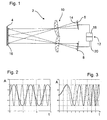
- FIG. 1 shows a device 2 for receiving images of an object scene 4 with an illumination unit 6, a detector 8 and an optical system 10 for directing radiation from illumination unit 6 into the object scene 4 and radiation reflected by the object scene 4 onto the detector 8.
- the transmit and receive aperture shown separately for clarity.
- a common aperture is also possible and associated with less effort in optical isolation compared to a pulse system.
- the peak power of the particular laser radiation can be kept low because the necessary energy through the Pulse length and the coding for the transit time measurement by a temporal modulation takes place.
- the lighting unit 6 comprises a rectangular grid of a plurality of lighting elements 14, which are each designed as a laser emitter and thus simultaneously form illumination sources. With the help of this laser raster, the object scene 4 is illuminated, wherein the control of the laser raster by means of a control unit 12 takes place. In FIG. 1 only the main rays of the optical image of the laser raster are shown on the detector 8. Instead of the laser grid, a grid of LEDs or another grid-shaped lighting unit can be used. In all lighting grids, it is advantageous if each lighting element of the grid is individually marked.
- each illumination element 14 illuminates a region 16 of the object scene.
- the assignment of each area 16 to a respective illumination element 14 is unique, so that each illumination element 14 illuminates exactly one area 16.
- the regions 16 are arranged in the form of a grid in the object scene 4, in particular in the same shape as the grid-shaped arrangement of the illumination elements 14.
- the object scene 4 or the individual regions 16 are imaged onto the detector 8 by the optics 10. As a result, each area 16 of the object scene 4 is assigned an image area on the detector 8, so that the areas 16 arranged in the form of a grid are also imaged in a grid on the detector 8.
- each illumination element 14 can be identified by the radiation emitted by it.
- the radiation is intrinsically modulated by assigning an individual carrier frequency to each illumination element.
- the radiation is already modulated in its formation in the semiconductor.
- other modulations are conceivable, for.
- external modulations such as by a hologram or a spatial light modulator, the radiation is a spatial modulation imposed.
- Microoptical, tunable interference filters are conceivable, the optical distances of the reflective surfaces are modulated independently.
- FIGS. 2 and 3 Two examples of possible markings are in the FIGS. 2 and 3 played.
- the amplitudes A of radiation from two illumination elements 14 are shown over the time t.
- the markers are frequency modulations in both examples.
- the carrier frequency of both lighting elements 14 is constant but different.
- the sharp frequencies or frequency ranges are in the diagrams FIG. 4 and FIG. 5 shown.
- the sharp frequencies f A , f B , f C , f ... are so far away from each other that they can be evaluated by the evaluation means 20 separated from each other.
- the in FIG. 5 shown frequency ranges or frequency bands of the frequency chirp not overlapping executed, but so far apart that even they can be evaluated clearly separated from the evaluation means 20 from each other.
- a fundamental frequency is linearly increased over time as in FIG. 3 is shown.
- the line spectrum of the carrier frequencies is broadened by the chirp into frequency bands, which in FIG. 5 are shown.
- the width of the frequency bands determines the minimum distance between the carrier frequencies of the individual lighting elements 14.
- the detector 8 is a single-cell detector with a single detector cell, to which the object scene 4 reflected radiation of all lighting elements 14 is guided.
- the detector 8 is expediently arranged in an image plane of the optics 10, with a deviation of not more than 10% of the focal length of the optics 10 being still acceptable as lying in the image plane.
- the signal output by the detector 8 and resulting from the illumination is evaluated by an evaluation means 20, which may be part of the control unit 12.
- This signal includes information from all the illuminated areas 16 since the detector 8 combines radiation information from all the illuminated areas 16 into one or more signals, each containing information from all areas 16 contains. From the one or more signals, however, a distinction of the individual lighting elements 14 or areas is possible by the marking. This distinction is made by the evaluation means 20.
- the evaluation means 20 can in each case assign information from the individual areas 16 to a channel, from which an image of the object scene 4 can be assembled by the known arrangement of the areas 16 in the object scene 4.
- Each area 16 can in this case provide a pixel, so that an overall two-dimensional image can be generated from the totality of the pixels.
- a position sensitive detector cell such as a lateral effect photodiode, as in FIG. 6 is shown in more detail.
- a photocurrent is generated, which flows in the direction of the p- and the n-doped region.
- a lateral effect photodiode has a plurality of electrical contacts, for example four electrical contacts or electrodes X 1 , X 2 , Y 1 , Y 2 . This results in a division of the photocurrent at these electrodes as a function of the position of the center of gravity of the irradiance of the light spot or the irradiation.
- the position in the x and y direction is determined by forming the current difference between two opposing electrodes. By normalizing to the total current, the position signal is independent of the incident light intensity. In this way, irradiation with the center of gravity in a first position 24 can be distinguished from the irradiation with the center of gravity in a second position 26.
- the position-sensitive detector cell measures the center of gravity of the irradiance within the detector surface 22, exemplified by two different positions 24, 26.
- the internal structure of the irradiance distribution e.g. As the image information can be extracted with the detector cell when the structural parts by means of a marker, for. B. temporal or frequency-like features are separable from each other. If, for example, each illumination element 14 differs by another carrier frequency, then each carrier frequency corresponds to a direction in the object space.
- the evaluation means 20 separates the individual carrier frequencies into different channels, which are processed independently of one another. This results in a determination of the positions 24, 26 on the active surface 22 of the detector cell for each detected carrier frequency. By imaging the object scene 4 onto the detector 8 or its detector cell, each position 24, 26 corresponds to a position within the object scene 4 or a region 16.
- An image of the object scene 4 can also be composed if the type of radiation is unknown or disturbed.
- the radiation from each illumination element 14 is modulated in such a way that it is possible to determine the transit time of an echo and thus to generate distance images by means of the echo method. It is also possible to scan the associated time signal at regular intervals and thus to create a three-dimensional volume image by screening the three-dimensional object space in voxels. From radar technology several methods of modulation for transit time determination and depth resolution are known. Another possible method of obtaining three-dimensional information is pseudo-noise coding.
- the result of the data merge is a three-dimensional image resolved by angle and distance.
Abstract
Description
Die Erfindung betrifft eine Vorrichtung zur Aufnahme von Bildern einer Objektszene mit einer Beleuchtungseinheit zum Beleuchten der Objektszene mit mehreren Beleuchtungselementen und einer Optik zum Lenken von aus der Objektszene reflektierter Strahlung der Beleuchtungselemente auf einen Detektor.The invention relates to a device for recording images of an object scene with a lighting unit for illuminating the object scene with a plurality of illumination elements and an optical system for directing reflected from the object scene radiation of the illumination elements to a detector.
Laserradare, also Sensoren, die eine Tiefenabtastung durchführen, arbeiten üblicherweise mit einer modulierten Laserquelle und einem Einelementdetektor, die im Spotmodus auf ein Objekt gerichtet sind oder über eine Szene gescannt werden. Ist die Zeitspanne zwischen zwei Scannpositionen ausreichend lang, so kann eine Auswertung des kompletten Zeitsignals ähnlich wie bei Mikrowellenradaren erfolgen. Erfolgt die Scannbewegung mit hoher Winkelgeschwindigkeit, also einer hohen Bildrate, so reduziert sich die Lasermodulation auf eine Folge kurzer Pulse und die Signalverarbeitung auf die Auswertungen der Laufzeit einiger weniger markanter Echos.Laser radars, ie sensors that perform a depth scan, usually work with a modulated laser source and a single-element detector, which are directed in spot mode at an object or scanned over a scene. If the time span between two scanning positions is sufficiently long, an evaluation of the complete time signal can be carried out similarly as with microwave radars. If the scanning movement is performed at high angular velocity, ie a high frame rate, then the laser modulation is reduced to a sequence of short pulses and the signal processing is reduced to evaluating the duration of a few marked echoes.
Es ist eine Aufgabe der Erfindung, eine einfache Vorrichtung anzugeben, mit der Aufnahmen von Bildern einer Objektszene gemacht werden können, insbesondere Bilder, die eine Tiefeninformation enthalten.It is an object of the invention to provide a simple device with which images of an object scene can be taken, in particular images containing depth information.
Diese Aufgabe wird gelöst durch eine Vorrichtung der eingangs genannten Art, die erfindungsgemäß ein Markiermittel zum Markieren der Strahlung aus jeder der Beleuchtungselemente und ein Auswertemittel zum Unterscheiden der reflektierten Strahlung der einzelnen Beleuchtungselemente anhand der Markierung umfasst. Durch die Mehrzahl der Beleuchtungselemente kann die Objektszene gleichzeitig oder sequentiell von den Beleuchtungselementen beleuchtet werden, wobei die Markierung bei der Auswertung der aufgenommenen Bilder eine Zuordnung der empfangenen Signale zu den einzelnen Beleuchtungselementen erlaubt. Hierdurch kann auf eine Scannmechanik verzichtet werden und die Vorrichtung kann einfach gehalten bleiben. Außerdem können einfache Detektoren verwendet werden, da eine Winkelzuordnung der einzelnen Signale allein oder zusätzlich mit Hilfe der Markierung der Strahlung erfolgen kann.This object is achieved by a device of the type mentioned above, which according to the invention comprises a marking means for marking the radiation from each of the lighting elements and an evaluation means for distinguishing the reflected radiation of the individual lighting elements by means of the marking. Due to the plurality of lighting elements, the object scene can be illuminated simultaneously or sequentially by the lighting elements, wherein the marking in the evaluation of the recorded images, an assignment of the received Signals to the individual lighting elements allowed. As a result, can be dispensed with a scanning mechanism and the device can be kept simple. In addition, simple detectors can be used, since an angular assignment of the individual signals can be done alone or in addition by means of the marking of the radiation.
Die Bilder der Objektszene können ein-, zwei- oder dreidimensional sein, flächig sein oder nur aus einzelnen, voneinander beabstandeten Bildpunkten bestehen und umfassen vorteilhafterweise eine Tiefeninformation. Die Vorrichtung ist zweckmäßigerweise ein Laserradar und die Beleuchtungselemente Laserelemente zum Abstrahlen von Laserstrahlung. Die Frequenz der Strahlung liegt insbesondere im infraroten Spektralbereich.The images of the object scene can be one-, two- or three-dimensional, flat or consist only of individual, spaced-apart pixels and advantageously comprise depth information. The device is expediently a laser radar and the illumination elements laser elements for emitting laser radiation. The frequency of the radiation is especially in the infrared spectral range.
In einer besonders einfachen und kostengünstigen Ausführung der Vorrichtung ist die Optik dazu ausgeführt, die gesamte zu einer Bilderzeugung auszuwertende reflektierte Strahlung der Beleuchtungselemente auf eine einzige Detektorzelle des Detektors zu lenken. Dieser umfasst zweckmäßigerweise nur die diese eine Detektorzelle. Aus dem Signal der Detektorzelle, das die Bildinformationen der reflektierten Strahlung aller Beleuchtungselemente in sich vereint, kann das Auswertemittel mit Hilfe der Markierung die Bildinformation in einzelne Kanäle aufteilen, die jeweils einem Beleuchtungselement zugeordnet sind. Ist bekannt, in welchen Bildbereich oder Bildpunkt die Strahlung eines jeden Beleuchtungselements gesendet wurde, so kann ein beispielsweise zweidimensionales Bild mit Hilfe nur der einen Detektorzelle erstellt werden. Unter einer Detektorzelle kann im Folgenden ein strahlungsempfindliches Element verstanden werden, das einen oder mehrere Signalausgänge umfasst, wobei alle Signalausgänge des Elements bei einer punktförmigen Beleuchtung des Elements mit einem der Beleuchtung entsprechenden Signal reagieren.In a particularly simple and cost-effective embodiment of the device, the optics are designed to direct the entire reflected radiation of the illumination elements, which is to be evaluated to form an image, onto a single detector cell of the detector. This expediently comprises only this one detector cell. From the signal of the detector cell, which unites the image information of the reflected radiation of all the illumination elements, the evaluation means can divide the image information into individual channels with the aid of the marking, which are each assigned to a lighting element. If it is known in which image area or pixel the radiation of each illumination element has been transmitted, an example of a two-dimensional image can be created with the aid of only one detector cell. In the following, a detector cell can be understood to mean a radiation-sensitive element which comprises one or more signal outputs, with all signal outputs of the element reacting with a signal corresponding to the illumination in the case of point-like illumination of the element.
Die Markierung kann durch eine Sendezeitmarkierung erfolgen. Hierzu ist das Markiermittel vorteilhafterweise zum Zuweisen eindeutiger Sendezeitfenster für jedes Beleuchtungselement vorgesehen. Die Sendezeitmarkierung kann durch eine zeitlich sequentielle Ansteuerung der Beleuchtungselemente erfolgen, sodass ein Zeitmultiplex unabhängiger Entfernungsmesser resultieren kann.The marking can be done by a transmission time marker. For this purpose, the marking means is advantageously provided for assigning unique transmission time windows for each lighting element. The transmission time marking can be effected by a temporally sequential control of the lighting elements, so that a time multiplex of independent rangefinders can result.
In einer besonders vorteilhaften Ausführungsform der Erfindung ist die Markierung eine Strahlfrequenzmarkierung, wobei die Beleuchtungselemente dazu vorgesehen sind, mit jeweils unterschiedlicher Frequenz abzustrahlen. Die Frequenz kann die Trägerfrequenz der Beleuchtungselemente sein, sodass zur Markierung die Trägerfrequenzen aller Beleuchtungselemente zueinander unterschiedlich sind. Anstelle oder zusätzlich zu den Trägerfrequenzen können Modulationsfrequenzen zur Markierung herangezogen werden. Auch die Verwendung unterschiedlicher Frequenzbereiche, beispielsweise durch unterschiedliche Frequenzchirps ist denkbar. Strahlen die Beleuchtungselemente selbst mit unterschiedlichen Strahlungs- bzw. Trägerfrequenzen, so kann die Beleuchtungseinheit zugleich Markiermittel sein. Ebenfalls denkbar ist, dass das Markiermittel eine Steuerung ist, die Strahlfrequenzen einstellt, z. B. durch Modulationen oder das Einstellen optischer Elemente.In a particularly advantageous embodiment of the invention, the marker is a beam frequency marker, wherein the illumination elements are intended to emit, each with a different frequency. The frequency can be the Be carrier frequency of the lighting elements, so that for marking the carrier frequencies of all lighting elements are different from each other. Instead of or in addition to the carrier frequencies modulation frequencies can be used for marking. The use of different frequency ranges, for example by different frequency chirps is conceivable. If the illumination elements irradiate themselves with different radiation or carrier frequencies, then the illumination unit can at the same time be marking means. It is also conceivable that the marking means is a control that adjusts beam frequencies, z. By modulations or adjustment of optical elements.
Vorteilhafterweise ist das Auswertemittel dazu ausgeführt, aus einer Markierungsanalyse Information aus der reflektierten Strahlung einer Position in einem Bild der Objektszene zuzuordnen. So kann das Auswertemittel beispielsweise dazu ausgeführt sein, durch eine Frequenzanalyse des Signals vom Detektor die Trennung der einzelnen Winkelkanäle vorzunehmen. Durch die Erzeugung von Winkelinformation und/oder Positionsinformation aus der Markierungsanalyse kann aus einem einzigen oder wenigen Information tragenden Signalen ein Bild, insbesondere ein mehrdimensionales Bild der Objektszene erzeugt werden.Advantageously, the evaluation means is designed to assign information from the reflected radiation to a position in an image of the object scene from a marking analysis. For example, the evaluation means may be designed to carry out the separation of the individual angular channels by frequency analysis of the signal from the detector. By generating angle information and / or position information from the marking analysis, an image, in particular a multi-dimensional image of the object scene, can be generated from a single or a few information-carrying signals.
Zum Erzeugen eines insbesondere mehrdimensionalen Bilds der Objektszene ist es vorteilhaft, wenn die Optik dazu ausgeführt ist, die Strahlung der einzelnen Beleuchtungsquellen jeweils in einen eigenen Bereich der Objektszene zu lenken. Die Bereiche sind in ihrer Lage in der Objektszene verschieden und überdecken sich zweckmäßigerweise nicht oder nur wenig. Die Bereiche können mehrdimensional ausgedehnte Bereiche oder punktförmig sein und beispielsweise voneinander beabstandet sein. Zweckmäßigerweise sind die Bereiche rasterförmig angeordnet, also gleichmäßig in einem ein- oder zweidimensionalen Gitter, wobei ein Rasterpunkt ein Schwerpunkt bzw. eine geometrische Mitte eines Bereichs sein kann.In order to generate a particularly multi-dimensional image of the object scene, it is advantageous if the optics is designed to direct the radiation of the individual illumination sources in each case into a separate region of the object scene. The areas are different in their location in the object scene and expediently do not overlap or only slightly. The regions may be multi-dimensionally extended regions or punctiform and, for example, spaced from one another. The areas are expediently arranged in the form of a grid, that is to say evenly in a one-dimensional or two-dimensional grid, wherein a grid point may be a center of gravity or a geometric center of a region.
Besonders einfach kann die Optik ausgeführt sein, wenn die Beleuchtungselemente rasterförmig angeordnet sind. Die Optik kann so das Flächenraster in ein Winkelraster transformieren, das besonders einfach auswertbar ist.The optics can be embodied particularly simply if the lighting elements are arranged in the form of a grid. The optics can thus transform the area grid into an angle grid, which is particularly easy to evaluate.
Die Beleuchtungselemente können zugleich Strahlung erzeugende Beleuchtungsquellen sein, beispielsweise einzelne Laserquellen. Es ist auch möglich, dass die Beleuchtungselemente Strahlung aus einer oder mehreren Beleuchtungsquellen empfangen und mit Hilfe der Optik in die Objektszene lenken.The illumination elements can also be radiation-generating illumination sources, for example individual laser sources. It is also possible for the illumination elements to receive radiation from one or more illumination sources and direct them into the object scene with the aid of the optics.
Vorteilhafterweise ist jedem Beleuchtungselement eine eigene Beleuchtungsquelle zugeordnet, wodurch eine Frequenzmarkierung direkt durch die Beleuchtungsquelle erfolgen kann. Es ist auch möglich, dass jedes Beleuchtungselement mit einem zugehörigen Modulationsmittel versehen ist, dass nur diesem Beleuchtungselement zugeordnet ist. Das Modulationsmittel kann ein Interferenzfilter sein, insbesondere ein durchstimmbarer Interferenzfilter, der vorteilhafterweise durch mikrooptische Elemente, die zweckmäßigerweise rasterförmig angeordnet sind, realisiert ist. Bei dieser Ausführungsform dieser Erfindung kann als Beleuchtungsquelle ein aufgeweiteter Laserstrahl verwendet werden, der zweckmäßigerweise alle Modulationsmittel bestrahlt und dessen Strahlung von allen Beleuchtungselementen verwendet werden kann. Als Modulationsmittel ist auch eine Bragg-Zelle geeignet, die mit einem Laserstrahl ausgeleuchtet werden kann. Die unterschiedlichen Beugungsordnungen besitzen unterschiedliche optische Trägerfrequenzen, die zur Markierungsanalyse vor der Detektion mit einem Lokaloszillator gemischt werden können.Advantageously, each lighting element is assigned its own illumination source, whereby a frequency marking can be made directly by the illumination source. It is also possible that each lighting element is provided with an associated modulation means that is associated with only this lighting element. The modulation means may be an interference filter, in particular a tunable interference filter, which is advantageously realized by micro-optical elements, which are expediently arranged in grid form. In this embodiment of this invention can be used as a source of illumination, an expanded laser beam, which expediently irradiated all the modulation means and its radiation can be used by all lighting elements. As a modulation means and a Bragg cell is suitable, which can be illuminated with a laser beam. The different orders of diffraction have different optical carrier frequencies, which can be mixed with a local oscillator for marking analysis prior to detection.
In einer weiteren vorteilhaften Ausführungsform der Erfindung umfasst die Vorrichtung ein Modulationsmittel zum zeitlichen Modulieren der Strahlung der Beleuchtungselemente, wobei das Auswertemittel zum Ermitteln einer Tiefeninformation aus einem Bild der Objektszene mit Hilfe der Modulation vorgesehen ist. Die Ermittlung kann durch eine Laufzeitmessung erfolgen, insbesondere mit langen Pulsen, mit charakteristischer intrinsischer Modulation. Auch eine kontinuierliche Beleuchtung ist denkbar. Die Auswertung erfolgt zweckmäßigerweise durch eine Korrelation mit einem elektronischen Referenzsignal. Vorteilhafterweise ist die Strahlung aus jedem Beleuchtungselement moduliert in der Weise, die es gestattet, die Laufzeit eines Echos zu bestimmen. Es ist auch möglich, das zugehörige Zeitsignal in regelmäßigen Abständen abzutasten und somit ein dreidimensionales Volumenbild zu erstellen. Auf diese Weise kann eine Rasterung eines dreidimensionalen Objektraums in Voxel erfolgen. Aus der Radartechnik sind mehrere Methoden der Modulation zur Laufzeitbestimmung und Tiefenauflösung bekannt.In a further advantageous embodiment of the invention, the device comprises a modulation means for temporally modulating the radiation of the illumination elements, wherein the evaluation means for determining a depth information from an image of the object scene by means of the modulation is provided. The determination can be carried out by a transit time measurement, in particular with long pulses, with characteristic intrinsic modulation. Even a continuous lighting is conceivable. The evaluation is expediently carried out by a correlation with an electronic reference signal. Advantageously, the radiation from each illumination element is modulated in the manner that allows to determine the duration of an echo. It is also possible to scan the associated time signal at regular intervals and thus to create a three-dimensional volume image. In this way, a rasterization of a three-dimensional object space in voxels can take place. From radar technology several methods of modulation for transit time determination and depth resolution are known.
Es wird außerdem vorgeschlagen, dass der Detektor eine positionsempfindliche Detektorzelle aufweist. Auf diese wird zweckmäßigerweise die reflektierte Strahlung aus den Beleuchtungselementen geleitet. Die positionsempfindliche Detektorzelle kann eine Lateraleffektfotodiode sein. Die Optik ist zweckmäßigerweise so ausgeführt, dass die Strahlung aus dem gesamten beleuchteten Winkelbereich auf die Detektorzelle leitet, sodass der gesamte beleuchtete Winkelbereich erfasst werden kann.It is also proposed that the detector comprises a position-sensitive detector cell. On this the expedient radiation is expediently conducted out of the illumination elements. The position sensitive detector cell may be a lateral effect photodiode. The optics are expediently designed so that the radiation from the entire illuminated angle range leads to the detector cell, so that the entire illuminated angle range can be detected.
Vorteilhafterweise ist das Auswertemittel dazu vorgesehen, aus der Markierungsinformation und den Signalen der positionsempfindlichen Detektorzelle eine Positionszuordnung von Strahlungsinformation der einzelnen Beleuchtungselemente durchzuführen. Auch auf diese Weise kann ein mehrdimensionales Bild mit Hilfe einer einzigen Detektorzelle erzeugt werden, wobei keine Information zur Senderichtung der einzelnen Beleuchtungselemente verwendet werden muss. Die Positionszuordnung im Bild bzw. Winkeldiskriminierung kann in jeder Markierung bzw. Trägerfrequenz durch die Messung der jeweiligen Flächenschwerpunkte der Bestrahlungsstärken erfolgen.Advantageously, the evaluation means is provided to perform a position assignment of radiation information of the individual lighting elements from the marking information and the signals of the position-sensitive detector cell. In this way too, a multi-dimensional image can be generated with the aid of a single detector cell, wherein no information on the transmission direction of the individual lighting elements has to be used. The position assignment in the image or angular discrimination can be carried out in each mark or carrier frequency by measuring the respective centroids of the irradiance.
Weitere Vorteile ergeben sich aus der folgenden Zeichnungsbeschreibung. In der Zeichnung sind Ausführungsbeispiele der Erfindung dargestellt. Die Zeichnung und die Beschreibung enthalten zahlreiche Merkmale in Kombination, die der Fachmann zweckmäßigerweise auch einzeln betrachten und zu sinnvollen weiteren Kombinationen zusammenfassen wird.Further advantages emerge from the following description of the drawing. In the drawings, embodiments of the invention are shown. The drawing and the description contain numerous features in combination, which the skilled person expediently consider individually and will summarize meaningful further combinations.
- Fig. 1Fig. 1
- eine schematische Übersichtsdarstellung einer Vorrichtung zur Aufnahme von Bildern einer Objektszene mit Hilfe mehrerer Beleuchtungsquellen und einer einzigen Detektorzelle,1 is a schematic overview of a device for taking pictures of an object scene using a plurality of illumination sources and a single detector cell,
- Fig. 2Fig. 2
- ein Diagramm mit zwei unterschiedlichen Beleuchtungsträgerfrequenzen,a diagram with two different illumination carrier frequencies,
- Fig. 3Fig. 3
- ein Diagramm mit zwei Frequenz-Chirps unterschiedlicher Frequenzen,a diagram with two frequency chirps of different frequencies,
- Fig. 4Fig. 4
-
ein Frequenzdiagramm mit scharfen Frequenzen analog zu
Figur 2 ,a frequency diagram with sharp frequencies analogous toFIG. 2 . - Fig. 5Fig. 5
-
ein Frequenzdiagramm mit Frequenzbereichen analog zu
Figur 3 unda frequency diagram with frequency ranges analog toFIG. 3 and - Fig. 6Fig. 6
- eine schematische Darstellung einer positionsempfindlichen Detektorzelle.a schematic representation of a position-sensitive detector cell.
Die Beleuchtungseinheit 6 umfasst ein rechtwinkliges Raster aus einer Vielzahl von Beleuchtungselementen 14, die jeweils als Laserstrahler ausgeführt sind und somit gleichzeitig Beleuchtungsquellen bilden. Mit Hilfe dieses Laserrasters wird die Objektszene 4 beleuchtet, wobei die Ansteuerung des Laserrasters mit Hilfe einer Steuereinheit 12 erfolgt. In
Die Strahlung aus der Beleuchtungseinheit 6 wird durch die Optik 10 in die Objektszene 4 geführt, wobei jedes Beleuchtungselement 14 einen Bereich 16 der Objektszene beleuchtet. Die Zuweisung eines jeden Bereichs 16 zu jeweils einem Beleuchtungselement 14 ist eindeutig, sodass jedes Beleuchtungselement 14 genau einen Bereich 16 beleuchtet. Die Bereiche 16 sind rasterförmig in der Objektszene 4 angeordnet, insbesondere in der gleichen Form wie die rasterförmige Anordnung der Beleuchtungselemente 14. Die Objektszene 4 bzw. die einzelnen Bereiche 16 werden durch die Optik 10 auf den Detektor 8 abgebildet. Hierdurch wird jedem Bereich 16 der Objektszene 4 ein Bildbereich auf dem Detektor 8 zugewiesen, sodass die rasterförmig angeordneten Bereiche 16 auch rasterförmig auf dem Detektor 8 abgebildet werden.The radiation from the
Die Strahlung aus den einzelnen Beleuchtungselementen 14 ist mit Hilfe eines elektronischen Markiermittels in der Form markiert, dass jedes Beleuchtungselement 14 durch die von ihm emittierte Strahlung identifizierbar ist. Bei dem in
Zwei Beispiele möglicher Markierungen sind in den
Die scharfen Frequenzen bzw. Frequenzbereiche sind in den Diagrammen aus
Im Frequenzchirp-Verfahren wird eine Grundfrequenz im zeitlichen Verlauf linear erhöht, wie in
Alternativ oder zusätzlich zu einer Frequenzmodulation wären auch einfache Phasenmessungen, einer Amplitudenmodulation, eine Phasenmodulation oder Pulskompressionsverfahren geeignet.Alternatively or additionally to a frequency modulation, simple phase measurements, an amplitude modulation, a phase modulation or a pulse compression method would also be suitable.
Der Detektor 8 ist ein Einzellendetektor mit einer einzigen Detektorzelle, auf die von der Objektszene 4 reflektierte Strahlung aller Beleuchtungselemente 14 geführt wird. Der Detektor 8 ist zweckmäßigerweise in einer Bildebene der Optik 10 angeordnet, wobei eine Abweichung von maximal 10 % der Brennweite der Optik 10 als noch in der Bildebene liegend akzeptabel sind.The
Das vom Detektor 8 ausgegebene und aus der Beleuchtung resultierende Signal wird von einem Auswertemittel 20 ausgewertet, das Teil der Steuereinheit 12 sein kann. Dieses Signal beinhaltet Information aus allen beleuchteten Bereichen 16, da der Detektor 8 Strahlungsinformation aus allen beleuchteten Bereichen 16 in ein oder mehrere Signale zusammenfasst, die jeweils Information aus allen Bereichen 16 enthält. Aus dem oder den einzelnen Signalen ist jedoch durch die Markierung eine Unterscheidung der einzelnen Beleuchtungselemente 14 bzw. Bereiche möglich. Diese Unterscheidung wird durch das Auswertemittel 20 vorgenommen. Auf diese Weise kann das Auswertemittel 20 Information aus den einzelnen Bereichen 16 jeweils einem Kanal zuordnen, aus denen - durch die bekannte Anordnung der Bereiche 16 in der Objektszene 4 - ein Bild der Objektszene 4 zusammengesetzt werden kann. Jeder Bereich 16 kann hierbei ein Pixel liefern, sodass aus der Gesamtheit der Pixel ein beispielsweise zweidimensionales Bild erzeugt werden kann.The signal output by the
Eine zusätzliche Positionsdiskriminierung bzw. Winkeldiskriminierung ist möglich bei der Verwendung einer positionsempfindlichen Detektorzelle, beispielsweise einer Lateraleffektfotodiode, wie in
Die positionsempfindliche Detektorzelle misst den Schwerpunkt der Bestrahlungsstärke innerhalb der Detektorfläche 22, beispielhaft dargestellt anhand von zwei verschiedenen Positionen 24, 26. Die innere Struktur der Bestrahlungsstärkeverteilung, z. B. die Bildinformation, kann mit der Detektorzelle extrahiert werden, wenn die Strukturteile mittels einer Markierung, z. B. zeitlicher oder frequenzartiger Merkmale, voneinander trennbar sind. Unterscheidet sich beispielsweise jedes Beleuchtungselement 14 durch eine andere Trägerfrequenz, so entspricht jede Trägerfrequenz einer Richtung im Objektraum. Das Auswertemittel 20 separiert die einzelnen Trägerfrequenzen in unterschiedliche Kanäle, die unabhängig voneinander prozessiert werden. Dadurch erfolgt eine Bestimmung der Positionen 24, 26 auf der aktiven Fläche 22 der Detektorzelle für jede detektierte Trägerfrequenz. Durch die Abbildung der Objektszene 4 auf den Detektor 8 bzw. dessen Detektorzelle entspricht jede Position 24, 26 einer Position innerhalb der Objektszene 4 bzw. einem Bereich 16.The position-sensitive detector cell measures the center of gravity of the irradiance within the
Durch die Trennbarkeit der Frequenzen und die dadurch mögliche Positionsbestimmung auf der aktiven Fläche 22 des Detektors 8 ist somit eine Positionsbestimmung bzw. Winkelbestimmung der einzelnen Bereiche 16 auch ohne die Kenntnis oder Verwendung der Abstrahlungsinformation der Beleuchtungseinheit 6 möglich. Ein Bild der Objektszene 4 kann auch dann zusammengesetzt werden, wenn die Art der Abstrahlung unbekannt oder gestört ist.Due to the separability of the frequencies and the possible position determination on the
Zusätzlich zu der Markierung ist die Strahlung von jedem Beleuchtungselement 14 so moduliert, dass es möglich ist, die Laufzeit eines Echos zu bestimmen und somit mit Hilfe des Echoverfahrens Entfernungsbilder zu erzeugen. Es ist auch möglich, das zugehörige Zeitsignal in regelmäßigen Abständen abzutasten und somit ein dreidimensionales Volumenbild durch eine Rasterung des dreidimensionalen Objektraums in Voxel zu erstellen. Aus der Radartechnik sind mehrere Methoden der Modulation zur Laufzeitbestimmung und Tiefenauflösung bekannt. Ein weiteres mögliches Verfahren zur Gewinnung von dreidimensionaler Information ist eine Pseudo-Noise-Codierung.In addition to the marking, the radiation from each
Nach der Gewinnung der Tiefeninformation kann diese mit den Positionsdaten bzw. Winkel-Winkel-Daten der Positionsbestimmung fusioniert werden. Das Ergebnis der Datenverschmelzung ist ein nach Winkel und Entfernung aufgelöstes dreidimensionales Bild.After obtaining the depth information, this can be fused with the position data or angle-angle data of the position determination. The result of the data merge is a three-dimensional image resolved by angle and distance.
- 22
- Vorrichtungcontraption
- 44
- Objektszeneobject scene
- 66
- Beleuchtungseinheitlighting unit
- 88th
- Detektordetector
- 1010
- Optikoptics
- 1212
- Steuereinheitcontrol unit
- 1414
- Beleuchtungselementlighting element
- 1616
- BereichArea
- 1818
- Markiermittelmarking means
- 2020
- Auswertemittelevaluation
- 2222
- Aktive FlächeActive area
- 2424
- Positionposition
- 2626
- Positionposition
- X1, X2 X 1 , X 2
- Elektrodeelectrode
- Y1, Y2 Y 1 , Y 2
- Elektrodeelectrode
Claims (14)
durch ein Markiermittel (18) zum Markieren der Strahlung aus jedem der Beleuchtungselemente (14) und ein Auswertemittel (20) zum Unterscheiden der reflektierten Strahlung der einzelnen Beleuchtungselemente (14) anhand der Markierung.Device (2) for taking pictures of an object scene (4) with an illumination unit (6) for illuminating the object scene (4) with a plurality of illumination elements (14) and optics (10) for directing radiation reflected from the object scene (4) Lighting elements (14) on a detector (8), characterized
by a marking means (18) for marking the radiation from each of the lighting elements (14) and an evaluation means (20) for distinguishing the reflected radiation of the individual lighting elements (14) from the marking.
dadurch gekennzeichnet,
dass die Optik (10) dazu ausgeführt ist, die gesamte zu einer Bilderzeugung auszuwertende reflektierte Strahlung der Beleuchtungselemente (14) auf eine einzige Detektorzelle des Detektors (8) zu lenken.Device (2) according to claim 1,
characterized,
in that the optics (10) are designed to direct the entire reflected radiation of the illumination elements (14), which is to be evaluated into an image formation, onto a single detector cell of the detector (8).
dadurch gekennzeichnet,
dass die Markierung eine Sendezeitmarkierung ist und das Markiermittel zum Zuweisen eindeutiger Sendezeitfenster für jedes Beleuchtungselement (14) vorgesehen ist.Device (2) according to claim 1 or 2,
characterized,
that the mark is a transmission time mark and the marking means is provided for assigning unique transmission time windows for each lighting element (14).
dadurch gekennzeichnet,
dass die Markierung eine Strahlfrequenzmarkierung ist und die Beleuchtungselemente (14) dazu vorgesehen sind, mit jeweils unterschiedlicher Frequenz abzustrahlen.Device (2) according to one of the preceding claims,
characterized,
in that the marking is a beam frequency marking and the illumination elements (14) are intended to emit at a different frequency in each case.
dadurch gekennzeichnet,
dass das Auswertemittel (20) dazu ausgeführt ist, aus einer Markierungsanalyse Information aus der reflektierten Strahlung einer Position in einem Bild der Objektszene (4) zuzuordnen.Device (2) according to one of the preceding claims,
characterized,
that the evaluation means (20) is adapted to assign information from the reflected radiation to a position in an image of the object scene (4) from a marking analysis.
dadurch gekennzeichnet,
dass das Auswertemittel (20) dazu vorgesehen ist, mit Hilfe mehrerer Positionszuordnungen ein Bild zu erzeugen.Device (2) according to claim 5,
characterized,
in that the evaluation means (20) is intended to generate an image with the aid of a plurality of position assignments.
dadurch gekennzeichnet,
dass die Optik (10) dazu ausgeführt ist, die Strahlung der einzelnen Beleuchtungselemente (14) jeweils in einen eigenen Bereich (16) der Objektszene (4) zu lenkenDevice (2) according to one of the preceding claims,
characterized,
in that the optic (10) is designed to direct the radiation of the individual illumination elements (14) in each case into a separate area (16) of the object scene (4)
dadurch gekennzeichnet,
dass die Optik (8) dazu ausgeführt ist, Strahlung aus den Beleuchtungselementen (14) rasterförmig in die Objektszene (4) zu lenken, wobei jedes Beleuchtungselement (14) genau einen Rasterpunkt beleuchtet.Device (2) according to one of the preceding claims,
characterized,
in that the optics (8) are designed to direct radiation from the illumination elements (14) into the object scene (4) in a grid pattern, each illumination element (14) illuminating exactly one grid point.
dadurch gekennzeichnet,
dass die Beleuchtungselemente (14) rasterförmig angeordnet sind.Device (2) according to one of the preceding claims,
characterized,
that the illumination elements (14) are arranged like a grid.
dadurch gekennzeichnet,
dass jedes Beleuchtungselement (14) eine eigene Beleuchtungsquelle umfasst.Device (2) according to one of the preceding claims,
characterized,
that each lighting element (14) comprises a separate illumination source.
dadurch gekennzeichnet,
dass jedes Beleuchtungselement (14) mit einem Modulationsmittel versehen ist, das nur diesem Beleuchtungselement (14) zugeordnet ist.Device (2) according to one of the preceding claims,
characterized,
in that each lighting element (14) is provided with a modulation means which is associated with only this lighting element (14).
gekennzeichnet
durch ein Modulationsmittel zum zeitlichen Modulieren der Strahlung der Beleuchtungselemente (14), wobei das Auswertemittel (20) zum Ermitteln einer Tiefeninformation aus einem Bild der Objektszene (4) mit Hilfe der Modulation vorgesehen ist.Device (2) according to one of the preceding claims,
marked
by a modulation means for temporally modulating the radiation of the illumination elements (14), wherein the evaluation means (20) for determining a depth information from an image of the object scene (4) by means of the modulation is provided.
dadurch gekennzeichnet,
dass der Detektor (8) eine positionsempfindliche Detektorzelle aufweist.Device (2) according to one of the preceding claims,
characterized,
that the detector (8) comprises a position sensitive detector cell.
dadurch gekennzeichnet,
dass das Auswertemittel (20) dazu vorgesehen ist, aus der Markierungsinformation und den Signalen der positionsempfindlichen Detektorzelle eine Positionszuordnung von Strahlungsinformation der einzelnen Beleuchtungselemente (14) durchzuführen.Device (2) according to claim 13,
characterized,
in that the evaluation means (20) is provided for carrying out a position assignment of radiation information of the individual illumination elements (14) from the marking information and the signals of the position-sensitive detector cell.
Applications Claiming Priority (1)
| Application Number | Priority Date | Filing Date | Title |
|---|---|---|---|
| DE102008052064A DE102008052064B4 (en) | 2008-10-17 | 2008-10-17 | Device for taking pictures of an object scene |
Publications (2)
| Publication Number | Publication Date |
|---|---|
| EP2177931A2 true EP2177931A2 (en) | 2010-04-21 |
| EP2177931A3 EP2177931A3 (en) | 2013-04-10 |
Family
ID=41667480
Family Applications (1)
| Application Number | Title | Priority Date | Filing Date |
|---|---|---|---|
| EP09012842.2A Withdrawn EP2177931A3 (en) | 2008-10-17 | 2009-10-10 | Device for recording images of an object scene |
Country Status (3)
| Country | Link |
|---|---|
| US (1) | US8605147B2 (en) |
| EP (1) | EP2177931A3 (en) |
| DE (1) | DE102008052064B4 (en) |
Cited By (11)
| Publication number | Priority date | Publication date | Assignee | Title |
|---|---|---|---|---|
| EP2388615A1 (en) * | 2010-05-17 | 2011-11-23 | Velodyne Acoustics, Inc. | High definition lidar system |
| USRE46672E1 (en) | 2006-07-13 | 2018-01-16 | Velodyne Lidar, Inc. | High definition LiDAR system |
| WO2019141641A1 (en) * | 2018-01-16 | 2019-07-25 | Robert Bosch Gmbh | Transmission device for emitting light |
| US10983218B2 (en) | 2016-06-01 | 2021-04-20 | Velodyne Lidar Usa, Inc. | Multiple pixel scanning LIDAR |
| US11073617B2 (en) | 2016-03-19 | 2021-07-27 | Velodyne Lidar Usa, Inc. | Integrated illumination and detection for LIDAR based 3-D imaging |
| US11082010B2 (en) | 2018-11-06 | 2021-08-03 | Velodyne Lidar Usa, Inc. | Systems and methods for TIA base current detection and compensation |
| US11137480B2 (en) | 2016-01-31 | 2021-10-05 | Velodyne Lidar Usa, Inc. | Multiple pulse, LIDAR based 3-D imaging |
| US11703569B2 (en) | 2017-05-08 | 2023-07-18 | Velodyne Lidar Usa, Inc. | LIDAR data acquisition and control |
| US11808891B2 (en) | 2017-03-31 | 2023-11-07 | Velodyne Lidar Usa, Inc. | Integrated LIDAR illumination power control |
| US11885958B2 (en) | 2019-01-07 | 2024-01-30 | Velodyne Lidar Usa, Inc. | Systems and methods for a dual axis resonant scanning mirror |
| US11933967B2 (en) | 2019-08-22 | 2024-03-19 | Red Creamery, LLC | Distally actuated scanning mirror |
Families Citing this family (4)
| Publication number | Priority date | Publication date | Assignee | Title |
|---|---|---|---|---|
| US20170168162A1 (en) * | 2015-12-09 | 2017-06-15 | The Boeing Company | Light detection and ranging (lidar) imaging systems and methods |
| WO2018134618A1 (en) * | 2017-01-19 | 2018-07-26 | Envisics Ltd. | Holographic light detection and ranging |
| JP7163555B2 (en) * | 2018-11-27 | 2022-11-01 | 株式会社AquaFusion | Underwater information visualization device |
| JP7260513B2 (en) * | 2020-08-20 | 2023-04-18 | 京セラ株式会社 | Ranging device, vehicle and ranging method |
Citations (6)
| Publication number | Priority date | Publication date | Assignee | Title |
|---|---|---|---|---|
| US5768461A (en) * | 1995-11-02 | 1998-06-16 | General Scanning, Inc. | Scanned remote imaging method and system and method of determining optimum design characteristics of a filter for use therein |
| DE10156282A1 (en) * | 2001-11-19 | 2003-06-12 | Martin Spies | Distance measurement image sensor has laser matrix, aperture with slot openings via which reflected laser light pulses are focused onto one or more receivers via intermediate optics |
| US20050111726A1 (en) * | 1998-07-08 | 2005-05-26 | Hackney Joshua J. | Parts manipulation and inspection system and method |
| US20060227317A1 (en) * | 2005-04-06 | 2006-10-12 | Henderson Sammy W | Efficient lidar with flexible target interrogation pattern |
| DE102005028570A1 (en) * | 2005-06-21 | 2006-12-28 | Diehl Bgt Defence Gmbh & Co. Kg | Object distance measuring device, has control unit to produce distance picture from signals of detector, and switchable selection unit through which radiation can be aligned in switchably changeable sample in object scene |
| DE102005049471A1 (en) * | 2005-10-13 | 2007-05-31 | Ingenieurbüro Spies GbR (vertretungsberechtigte Gesellschafter: Hans Spies, Martin Spies, 86558 Hohenwart) | Distance image sensor for measuring distance of electromagnetic impulses, has receiver that is charged by formation of entire surface of reception optics on mirror array and passage array |
Family Cites Families (20)
| Publication number | Priority date | Publication date | Assignee | Title |
|---|---|---|---|---|
| US5717422A (en) * | 1994-01-25 | 1998-02-10 | Fergason; James L. | Variable intensity high contrast passive display |
| US6057909A (en) * | 1995-06-22 | 2000-05-02 | 3Dv Systems Ltd. | Optical ranging camera |
| US6445884B1 (en) * | 1995-06-22 | 2002-09-03 | 3Dv Systems, Ltd. | Camera with through-the-lens lighting |
| CA2436596C (en) * | 2000-01-25 | 2005-10-25 | 4D-Vision Gmbh | Method and arrangement for the three-dimensional display |
| JP4574057B2 (en) * | 2000-05-08 | 2010-11-04 | キヤノン株式会社 | Display device |
| CA2364601A1 (en) * | 2001-12-03 | 2003-06-03 | Utar Scientific Inc. | Computer-assisted hologram forming method and apparatus |
| US8243004B2 (en) * | 2003-03-10 | 2012-08-14 | Fergason Patent Properties, Llc | Apparatus and method for preparing, storing, transmitting and displaying images |
| JP4316916B2 (en) * | 2003-04-04 | 2009-08-19 | 大日本印刷株式会社 | Computer-generated hologram |
| US7274815B1 (en) * | 2003-10-09 | 2007-09-25 | Sandia Corporation | Parallel phase-sensitive three-dimensional imaging camera |
| DE102004020663A1 (en) * | 2004-04-24 | 2005-11-10 | Carl Zeiss Meditec Ag | Device for lighting organic objects |
| US7362419B2 (en) * | 2004-09-17 | 2008-04-22 | Matsushita Electric Works, Ltd. | Range image sensor |
| JP4797593B2 (en) * | 2005-03-10 | 2011-10-19 | 富士ゼロックス株式会社 | Gloss measuring apparatus and program |
| DE102005021808B4 (en) * | 2005-05-04 | 2010-02-18 | Fraunhofer-Gesellschaft zur Förderung der angewandten Forschung e.V. | Device for illuminating an object |
| WO2007036553A1 (en) * | 2005-09-30 | 2007-04-05 | Siemens Aktiengesellschaft | Device and method for recording distance images |
| US7283363B2 (en) * | 2006-01-20 | 2007-10-16 | Stirring Enetrprise Co., Ltd. | Computer casing |
| DE102006029025A1 (en) * | 2006-06-14 | 2007-12-27 | Iris-Gmbh Infrared & Intelligent Sensors | Reflective object distance determining device, has two integrators connected with photoelectric unit and control input, where photoelectric unit is rectangle or square shape and exhibits specific side length |
| WO2008082506A1 (en) * | 2006-12-19 | 2008-07-10 | J.A. Woollam Co., Inc. | Application of digital light processor in scanning spectrometer and imaging ellipsometer and the like systems |
| DE102007012624B3 (en) * | 2007-03-16 | 2008-06-12 | K.A. Schmersal Holding Kg | Apparatus to generate a three-dimensional distance image eliminates or corrects measurement errors through false reflections and the like |
| EP1972930B1 (en) * | 2007-03-19 | 2019-11-13 | Concast Ag | Method for identifying surface characteristics of metallurgical products, in particular continuous casting and milling products, and device for implementing the method |
| CN101715589B (en) * | 2007-04-24 | 2014-01-22 | 锡克拜控股有限公司 | Method of marking articles, method and device for marking articles, use of circularly polarised particles |
-
2008
- 2008-10-17 DE DE102008052064A patent/DE102008052064B4/en not_active Expired - Fee Related
-
2009
- 2009-09-10 US US12/557,226 patent/US8605147B2/en not_active Expired - Fee Related
- 2009-10-10 EP EP09012842.2A patent/EP2177931A3/en not_active Withdrawn
Patent Citations (6)
| Publication number | Priority date | Publication date | Assignee | Title |
|---|---|---|---|---|
| US5768461A (en) * | 1995-11-02 | 1998-06-16 | General Scanning, Inc. | Scanned remote imaging method and system and method of determining optimum design characteristics of a filter for use therein |
| US20050111726A1 (en) * | 1998-07-08 | 2005-05-26 | Hackney Joshua J. | Parts manipulation and inspection system and method |
| DE10156282A1 (en) * | 2001-11-19 | 2003-06-12 | Martin Spies | Distance measurement image sensor has laser matrix, aperture with slot openings via which reflected laser light pulses are focused onto one or more receivers via intermediate optics |
| US20060227317A1 (en) * | 2005-04-06 | 2006-10-12 | Henderson Sammy W | Efficient lidar with flexible target interrogation pattern |
| DE102005028570A1 (en) * | 2005-06-21 | 2006-12-28 | Diehl Bgt Defence Gmbh & Co. Kg | Object distance measuring device, has control unit to produce distance picture from signals of detector, and switchable selection unit through which radiation can be aligned in switchably changeable sample in object scene |
| DE102005049471A1 (en) * | 2005-10-13 | 2007-05-31 | Ingenieurbüro Spies GbR (vertretungsberechtigte Gesellschafter: Hans Spies, Martin Spies, 86558 Hohenwart) | Distance image sensor for measuring distance of electromagnetic impulses, has receiver that is charged by formation of entire surface of reception optics on mirror array and passage array |
Non-Patent Citations (2)
| Title |
|---|
| JANUSZ A. MARSZALEC ET AL: "<title>Range imaging sensor with no moving parts</title>", PROCEEDINGS OF SPIE, Bd. 2783, 26. August 1996 (1996-08-26), Seiten 316-324, XP055055006, ISSN: 0277-786X, DOI: 10.1117/12.248502 * |
| YOUNG MIN KIM ET AL: "Design and calibration of a multi-view TOF sensor fusion system", COMPUTER VISION AND PATTERN RECOGNITION WORKSHOPS, 2008. CVPR WORKSHOPS 2008. IEEE COMPUTER SOCIETY CONFERENCE ON, IEEE, PISCATAWAY, NJ, USA, 23. Juni 2008 (2008-06-23), Seiten 1-7, XP031285716, ISBN: 978-1-4244-2339-2 * |
Cited By (27)
| Publication number | Priority date | Publication date | Assignee | Title |
|---|---|---|---|---|
| USRE48666E1 (en) | 2006-07-13 | 2021-08-03 | Velodyne Lidar Usa, Inc. | High definition LiDAR system |
| USRE46672E1 (en) | 2006-07-13 | 2018-01-16 | Velodyne Lidar, Inc. | High definition LiDAR system |
| USRE48688E1 (en) | 2006-07-13 | 2021-08-17 | Velodyne Lidar Usa, Inc. | High definition LiDAR system |
| USRE47942E1 (en) | 2006-07-13 | 2020-04-14 | Velodyne Lindar, Inc. | High definition lidar system |
| US8767190B2 (en) | 2006-07-13 | 2014-07-01 | Velodyne Acoustics, Inc. | High definition LiDAR system |
| USRE48490E1 (en) | 2006-07-13 | 2021-03-30 | Velodyne Lidar Usa, Inc. | High definition LiDAR system |
| USRE48491E1 (en) | 2006-07-13 | 2021-03-30 | Velodyne Lidar Usa, Inc. | High definition lidar system |
| USRE48504E1 (en) | 2006-07-13 | 2021-04-06 | Velodyne Lidar Usa, Inc. | High definition LiDAR system |
| USRE48503E1 (en) | 2006-07-13 | 2021-04-06 | Velodyne Lidar Usa, Inc. | High definition LiDAR system |
| EP2388615A1 (en) * | 2010-05-17 | 2011-11-23 | Velodyne Acoustics, Inc. | High definition lidar system |
| US11698443B2 (en) | 2016-01-31 | 2023-07-11 | Velodyne Lidar Usa, Inc. | Multiple pulse, lidar based 3-D imaging |
| US11822012B2 (en) | 2016-01-31 | 2023-11-21 | Velodyne Lidar Usa, Inc. | Multiple pulse, LIDAR based 3-D imaging |
| US11550036B2 (en) | 2016-01-31 | 2023-01-10 | Velodyne Lidar Usa, Inc. | Multiple pulse, LIDAR based 3-D imaging |
| US11137480B2 (en) | 2016-01-31 | 2021-10-05 | Velodyne Lidar Usa, Inc. | Multiple pulse, LIDAR based 3-D imaging |
| US11073617B2 (en) | 2016-03-19 | 2021-07-27 | Velodyne Lidar Usa, Inc. | Integrated illumination and detection for LIDAR based 3-D imaging |
| US11550056B2 (en) | 2016-06-01 | 2023-01-10 | Velodyne Lidar Usa, Inc. | Multiple pixel scanning lidar |
| US10983218B2 (en) | 2016-06-01 | 2021-04-20 | Velodyne Lidar Usa, Inc. | Multiple pixel scanning LIDAR |
| US11808854B2 (en) | 2016-06-01 | 2023-11-07 | Velodyne Lidar Usa, Inc. | Multiple pixel scanning LIDAR |
| US11561305B2 (en) | 2016-06-01 | 2023-01-24 | Velodyne Lidar Usa, Inc. | Multiple pixel scanning LIDAR |
| US11874377B2 (en) | 2016-06-01 | 2024-01-16 | Velodyne Lidar Usa, Inc. | Multiple pixel scanning LIDAR |
| US11808891B2 (en) | 2017-03-31 | 2023-11-07 | Velodyne Lidar Usa, Inc. | Integrated LIDAR illumination power control |
| US11703569B2 (en) | 2017-05-08 | 2023-07-18 | Velodyne Lidar Usa, Inc. | LIDAR data acquisition and control |
| CN111630407A (en) * | 2018-01-16 | 2020-09-04 | 罗伯特·博世有限公司 | Emitting device for emitting light |
| WO2019141641A1 (en) * | 2018-01-16 | 2019-07-25 | Robert Bosch Gmbh | Transmission device for emitting light |
| US11082010B2 (en) | 2018-11-06 | 2021-08-03 | Velodyne Lidar Usa, Inc. | Systems and methods for TIA base current detection and compensation |
| US11885958B2 (en) | 2019-01-07 | 2024-01-30 | Velodyne Lidar Usa, Inc. | Systems and methods for a dual axis resonant scanning mirror |
| US11933967B2 (en) | 2019-08-22 | 2024-03-19 | Red Creamery, LLC | Distally actuated scanning mirror |
Also Published As
| Publication number | Publication date |
|---|---|
| DE102008052064A1 (en) | 2010-04-22 |
| US8605147B2 (en) | 2013-12-10 |
| EP2177931A3 (en) | 2013-04-10 |
| US20100097459A1 (en) | 2010-04-22 |
| DE102008052064B4 (en) | 2010-09-09 |
Similar Documents
| Publication | Publication Date | Title |
|---|---|---|
| DE102008052064B4 (en) | Device for taking pictures of an object scene | |
| EP3729137B1 (en) | Multi-pulse lidar system for multi-dimensional detection of objects | |
| DE69635858T2 (en) | TELECENTRIC 3D CAMERA AND RELATED METHOD | |
| AT412032B (en) | METHOD FOR RECORDING AN OBJECT SPACE | |
| EP3633405B1 (en) | Measuring apparatus for geometric 3d-scanning of an environment having a plurality of emission channels and semiconductor photomultiplier sensors | |
| EP2019973B1 (en) | Distance measuring method and distance meter for determining the spatial dimension of a target | |
| WO1999028765A1 (en) | Device for reading out information stored in a phosphor-carrier, and an x-ray cassette | |
| DE10139237A1 (en) | Distance measuring device | |
| DE102018222718A1 (en) | Optoelectronic sensor, method and vehicle | |
| DE102009055626A1 (en) | Optical measuring device for optical measurement of maize plant, has evaluation device evaluating distance signal of camera pixels to determine three-dimensional enveloped surface of measuring object to be detected in measuring region | |
| DE102018108340A1 (en) | Opto-electronic sensor and method for detection and distance determination of objects | |
| DE102009046108A1 (en) | camera system | |
| WO2019234034A1 (en) | Operating method for a lidar system, control unit, lidar system, and device | |
| EP3488258A1 (en) | Optical arrangement for a lidar system, lidar system, and working device | |
| DE3436275A1 (en) | DEVICE FOR GENERATING IMAGES WITH A HIGH RESOLUTION CAPACITY WITHOUT PRECISION OPTICS | |
| DE102020206006A1 (en) | Method for calibrating and / or adjusting and control unit for a LiDAR system, LiDAR system and working device | |
| EP2013642A1 (en) | Device and method for recording distance images | |
| DE102018200620A1 (en) | Transmitting device for emitting light | |
| DE4304815A1 (en) | Optical sensor | |
| WO2019110206A1 (en) | Lidar system for surroundings detection and method for operating a lidar system | |
| DE2526110A1 (en) | DEVICE FOR MEASURING SMALL DIFFERENCES | |
| DE2340688C3 (en) | Reading device for optically detectable digital codes | |
| DE102005024271A1 (en) | Grating spectrometer system and method for measured value acquisition | |
| DE1805286A1 (en) | Optical correlator | |
| DE102019217165A1 (en) | Operating method and control unit for a LiDAR system, LiDAR system and device |
Legal Events
| Date | Code | Title | Description |
|---|---|---|---|
| PUAI | Public reference made under article 153(3) epc to a published international application that has entered the european phase |
Free format text: ORIGINAL CODE: 0009012 |
|
| AK | Designated contracting states |
Kind code of ref document: A2 Designated state(s): AT BE BG CH CY CZ DE DK EE ES FI FR GB GR HR HU IE IS IT LI LT LU LV MC MK MT NL NO PL PT RO SE SI SK SM TR |
|
| AX | Request for extension of the european patent |
Extension state: AL BA RS |
|
| PUAL | Search report despatched |
Free format text: ORIGINAL CODE: 0009013 |
|
| AK | Designated contracting states |
Kind code of ref document: A3 Designated state(s): AT BE BG CH CY CZ DE DK EE ES FI FR GB GR HR HU IE IS IT LI LT LU LV MC MK MT NL NO PL PT RO SE SI SK SM TR |
|
| AX | Request for extension of the european patent |
Extension state: AL BA RS |
|
| RIC1 | Information provided on ipc code assigned before grant |
Ipc: G01S 7/481 20060101AFI20130307BHEP Ipc: G01S 17/89 20060101ALI20130307BHEP |
|
| 17P | Request for examination filed |
Effective date: 20130917 |
|
| RBV | Designated contracting states (corrected) |
Designated state(s): AT BE BG CH CY CZ DE DK EE ES FI FR GB GR HR HU IE IS IT LI LT LU LV MC MK MT NL NO PL PT RO SE SI SK SM TR |
|
| GRAP | Despatch of communication of intention to grant a patent |
Free format text: ORIGINAL CODE: EPIDOSNIGR1 |
|
| INTG | Intention to grant announced |
Effective date: 20161219 |
|
| RAP1 | Party data changed (applicant data changed or rights of an application transferred) |
Owner name: DIEHL DEFENCE GMBH & CO. KG |
|
| STAA | Information on the status of an ep patent application or granted ep patent |
Free format text: STATUS: THE APPLICATION IS DEEMED TO BE WITHDRAWN |
|
| 18D | Application deemed to be withdrawn |
Effective date: 20170503 |